WO2018105065A1 - 回転機械の設置方法、及び回転機械 - Google Patents
回転機械の設置方法、及び回転機械 Download PDFInfo
- Publication number
- WO2018105065A1 WO2018105065A1 PCT/JP2016/086413 JP2016086413W WO2018105065A1 WO 2018105065 A1 WO2018105065 A1 WO 2018105065A1 JP 2016086413 W JP2016086413 W JP 2016086413W WO 2018105065 A1 WO2018105065 A1 WO 2018105065A1
- Authority
- WO
- WIPO (PCT)
- Prior art keywords
- base plate
- support leg
- level
- rotary machine
- level adjustment
- Prior art date
- Legal status (The legal status is an assumption and is not a legal conclusion. Google has not performed a legal analysis and makes no representation as to the accuracy of the status listed.)
- Ceased
Links
Images



Classifications
-
- E—FIXED CONSTRUCTIONS
- E02—HYDRAULIC ENGINEERING; FOUNDATIONS; SOIL SHIFTING
- E02D—FOUNDATIONS; EXCAVATIONS; EMBANKMENTS; UNDERGROUND OR UNDERWATER STRUCTURES
- E02D27/00—Foundations as substructures
- E02D27/32—Foundations for special purposes
- E02D27/44—Foundations for machines, engines or ordnance
-
- F—MECHANICAL ENGINEERING; LIGHTING; HEATING; WEAPONS; BLASTING
- F04—POSITIVE - DISPLACEMENT MACHINES FOR LIQUIDS; PUMPS FOR LIQUIDS OR ELASTIC FLUIDS
- F04B—POSITIVE-DISPLACEMENT MACHINES FOR LIQUIDS; PUMPS
- F04B39/00—Component parts, details, or accessories, of pumps or pumping systems specially adapted for elastic fluids, not otherwise provided for in, or of interest apart from, groups F04B25/00 - F04B37/00
- F04B39/12—Casings; Cylinders; Cylinder heads; Fluid connections
- F04B39/121—Casings
-
- F—MECHANICAL ENGINEERING; LIGHTING; HEATING; WEAPONS; BLASTING
- F04—POSITIVE - DISPLACEMENT MACHINES FOR LIQUIDS; PUMPS FOR LIQUIDS OR ELASTIC FLUIDS
- F04B—POSITIVE-DISPLACEMENT MACHINES FOR LIQUIDS; PUMPS
- F04B39/00—Component parts, details, or accessories, of pumps or pumping systems specially adapted for elastic fluids, not otherwise provided for in, or of interest apart from, groups F04B25/00 - F04B37/00
- F04B39/14—Provisions for readily assembling or disassembling
-
- F—MECHANICAL ENGINEERING; LIGHTING; HEATING; WEAPONS; BLASTING
- F04—POSITIVE - DISPLACEMENT MACHINES FOR LIQUIDS; PUMPS FOR LIQUIDS OR ELASTIC FLUIDS
- F04B—POSITIVE-DISPLACEMENT MACHINES FOR LIQUIDS; PUMPS
- F04B35/00—Piston pumps specially adapted for elastic fluids and characterised by the driving means to their working members, or by combination with, or adaptation to, specific driving engines or motors, not otherwise provided for
- F04B35/04—Piston pumps specially adapted for elastic fluids and characterised by the driving means to their working members, or by combination with, or adaptation to, specific driving engines or motors, not otherwise provided for the means being electric
-
- F—MECHANICAL ENGINEERING; LIGHTING; HEATING; WEAPONS; BLASTING
- F04—POSITIVE - DISPLACEMENT MACHINES FOR LIQUIDS; PUMPS FOR LIQUIDS OR ELASTIC FLUIDS
- F04C—ROTARY-PISTON, OR OSCILLATING-PISTON, POSITIVE-DISPLACEMENT MACHINES FOR LIQUIDS; ROTARY-PISTON, OR OSCILLATING-PISTON, POSITIVE-DISPLACEMENT PUMPS
- F04C2230/00—Manufacture
- F04C2230/60—Assembly methods
Definitions
- the present invention relates to a rotary machine installation method and a rotary machine.
- a rotating machine body having a rotating shaft is supported by a support leg.
- a plurality of support legs are fixed on a base plate installed on the foundation.
- the rotary machine is installed by installing the rotary machine body on the fixed support leg.
- the present invention provides a rotating machine installation method and a rotating machine that can ensure the level of the rotating machine by adjusting the position of the support leg with respect to the base plate.
- a rotary machine installation method is a rotary machine installation method including a plurality of support legs extending in a vertical direction and a rotary machine body fixed to an upper end portion of the support legs. And preparing a base plate for supporting the support leg on the foundation, and arranging a level adjusting member having a plurality of wedge shapes along the outer shape of the lower end portion of the support leg on the base plate.
- a level adjusting member arranging step a placing step of placing the support legs on the plurality of level adjusting members, and adjusting a push amount of the level adjusting member to a lower end portion of the support legs,
- An adjusting step of adjusting a horizontal level of the rotating machine body and a fixing step of fixing the positions of the support leg and the level adjusting member with respect to the base plate by welding the supporting leg and the plurality of level adjusting members.
- the horizontal level of the upper end of the support leg can be adjusted by adjusting the amount of pushing the wedge-shaped level adjusting member into the lower end of the support leg. Therefore, level adjustment with respect to the base plate of the rotating machine main body fixed to the support leg can be easily and reliably performed.
- the rotating machine installation method further includes a liner member arranging step of arranging a flat liner member on the base plate before the level adjusting member arranging step. And in the level adjusting member arranging step, the plurality of level adjusting members are arranged on the liner member fixed to the base plate, and in the fixing step, the support legs and the plurality of level adjusting members are It may be welded to the liner member.
- the level adjusting member can be disposed on the smooth surface of the flat liner member. Therefore, the level adjusting member can be easily moved when adjusting the amount by which the level adjusting member is pushed downward of the support leg.
- the preparation step removes the existing support legs fixed on the base plate from the base plate. You may do it.
- the new rotating machine main body and the support legs can be installed using the base plate on which the existing support legs are fixed. Therefore, there is no need to re-install the base plate, and work efficiency and cost reduction can be achieved.
- a rotating machine is mounted on a base plate installed on a foundation, a plurality of wedge-shaped level adjusting members provided on the base plate, and a plurality of the level adjusting members.
- a plurality of support legs that extend in the vertical direction, and are formed by welding a lower end portion of the support legs and a plurality of the level adjustment members, and the base plate of the support legs and the level adjustment members And a rotating machine body supported by the plurality of support legs.
- the level of the rotary machine body relative to the base plate can be adjusted easily and reliably.
- the first compressor 1 that is an existing compressor includes a base plate 3, a plurality of (for example, four in this embodiment) first support legs (support legs) 4, and a first compressor 1.
- the base plate 3 is provided on the foundation 2 constructed on the ground.
- the base plate 3 can support the first support legs 4.
- the base plate 3 has a rectangular frame shape in plan view, for example, by combining a plurality of steel materials.
- the first support leg 4 is joined and fixed on the base plate 3.
- the first support leg 4 extends in the vertical direction Dv.
- the lower end 4 a of the first support leg 4 is directly welded onto the base plate 3.
- the first support leg 4 extends upward in the vertical direction Dv from the lower end 4a toward the upper end 4b.
- the first compressor body 5 includes a casing 5a that forms an outer shell thereof, and a supported portion 5b that protrudes outward from the outer peripheral surface of the casing 5a.
- the first compressor body 5 is integrally formed with the plurality of first support legs 4 by joining the supported parts 5b in a state of being placed on the upper end parts 4b of the first support legs 4. Yes.
- the first compressor body 5 is removed from the plurality of first support legs 4 (compressor body removal step S1). Specifically, the upper end 4b of the first support leg 4 and the supported part 5b are cut by fusing or the like, and the first support leg 4 and the first compressor body 5 are cut off. Thereafter, the first compressor body 5 is removed from the first support leg 4.
- the base plate 3 is prepared on the foundation by removing the first support legs 4 fixed on the base plate 3 from the base plate 3 (preparation step S2). . Specifically, the lower end 4a of each first support leg 4 and the base plate 3 are cut by, for example, fusing. Thereafter, the plurality of first support legs 4 are removed from the base plate 3. After the first support leg 4 is removed from the base plate 3, the portion of the base plate 3 joined to the first support leg 4 is polished so as to eliminate unevenness. Thereby, preparation of the baseplate 3 which supports a support leg is completed. Thereafter, the second support leg 14 and the second compressor body (rotary machine body) 15 (see FIG. 8) of the second compressor 10 which is a new compressor are installed on the base plate 3.
- the second support leg 14 extends in the vertical direction Dv similarly to the first support leg 4.
- the second support leg 14 extends upward in the vertical direction Dv from the lower end portion 14a toward the upper end portion 14b.
- the second compressor body 15 includes a casing 15a that forms an outer shell thereof, and a supported portion 15b that protrudes outward from the outer peripheral surface of the casing 15a.
- the second support leg 14 which is a new support leg on the base plate 3, is installed before a level adjusting member arranging step S ⁇ b> 4 described later.
- a new liner plate (liner member) 16 is installed at the location (liner member arrangement step S3).
- the liner plate 16 has a rectangular flat plate shape.
- the liner plate 16 is made of the same steel material as the base plate 3.
- the liner plate 16 is disposed at an installation position of the second compressor 10 which is a new compressor described later.
- the liner plate 16 is integrally fixed to the base plate 3 by welding the outer peripheral portion 16 a of the liner plate 16 to the upper surface 3 f of the base plate 3.
- the liner plate 16 may be disposed so as to overlap the portion where the first support leg 4 of the base plate 3 is joined.
- a plurality of level adjustment members 17 are arranged on the base plate 3 along the outer shape of the lower end portion 14a of the second support leg 14 (level adjustment member arrangement step S4).
- a plurality of level adjusting members 17 are arranged on the liner plate 16 fixed to the base plate 3.
- the level adjusting member 17 has a wedge shape in which the height dimension gradually decreases toward the tip end portion 17a.
- the level adjustment member 17 is formed of the same steel material as the base plate 3.
- the plurality of level adjusting members 17 are preferably arranged at equal intervals in the circumferential direction along the outer shape of the lower end portion 14 a of the second support leg 14. Further, each level adjusting member 17 is arranged with the tip end portion 17a facing the inside of the second support leg 14 when viewed from above in the vertical direction Dv.
- the second support leg 14 of the second compressor 10 which is a new compressor, and the second compressor main body (rotary machine main body) 15 (see FIG. 8) are placed (placement step S5).
- the second support leg 14 is placed on the plurality of level adjusting members 17.
- the tip 17a of the level adjustment member 17 is sandwiched between the second support leg 14 and the liner plate 16, and a part of the level adjustment member 17 protrudes outward from the second support leg 14. It becomes.
- the second support leg 14 may be integrally attached to the second compressor body 15 in advance, and after the second support leg 14 is fixed to the base plate 3, the second support leg 14 is attached to the second compressor leg 15. You may attach with the compressor main body 15. FIG.
- the second compressor body 15 to which the plurality of second support legs 14 are attached is suspended, and each second support leg 14 is attached to the liner. It is placed on a plurality of level adjusting members 17 set on the plate 16. Thus, the plurality of level adjusting members 17 are interposed between the liner plate 16 and the second support legs 14.
- the horizontal level of the second compressor body 15 is adjusted by adjusting the amount by which the level adjusting member 17 is pushed into the lower end portion 14 a of the second support leg 14 (adjustment step S ⁇ b> 6). .
- the level adjustment member 17 is driven into the back between the liner plate 16 and the second support leg 14 with a hammer 20 or the like.
- the pushing amount of the level adjustment member 17 with respect to the lower end part 14a of the 2nd support leg 14 is adjusted. Since the level adjusting member 17 has a wedge shape, the height of the upper end portion 14b of the second support leg 14 is adjusted by adjusting the push-in amount.
- the height of the supported portion 15b of the second compressor body 15 placed on the upper end portion 14b of the second support leg 14 is adjusted.
- the horizontal level adjustment of the second compressor body 15 is performed so that the rotation shaft (not shown) provided in the second compressor body 15 is horizontal.
- the lower end portion 14 a of each second support leg 14, the liner plate 16, and the level adjustment member 17 are welded. Thereby, a position is fixed with respect to the base plate 3 of the 2nd support leg 14 and the level adjustment member 17 (fixing process S7).
- the lower end portion 14a of the second support leg 14 and the liner plate 16 are continuously welded over the entire circumference of the lower end portion 14a of the second support leg 14 so that the level adjusting member 17 is wound around.
- the weld bead (fixed portion) 21 is formed so as to cover the lower end portion 14a of the second support leg 14 from the circumferential direction.
- the plurality of level adjusting members 17 interposed between the liner plate 16 and each of the second support legs 14 are joined to the liner plate 16 so as to be integrated with the second support legs 14 by welding beads 21.
- the weld bead 21 is formed by welding the lower end portion 14 a of the second support leg 14 and the plurality of level adjusting members 17.
- the weld bead 21 fixes the position of the second support leg 14 and the level adjusting member 17 with respect to the base plate 3 via the liner plate 16.
- the existing first compressor 1 can be replaced with the newly installed second compressor 10 and installed. Therefore, the second compressor 10 includes the base plate 3, the liner plate 16, the level adjusting member 17, the second support leg 14, the weld bead 21, and the second compressor body 15.
- the amount of the wedge-shaped level adjusting member 17 pushed into the lower end portion 14a of the second support leg 14 is adjusted, whereby the second level with respect to the base plate 3 is adjusted.
- the horizontal level of the upper end portion 14b of the two support legs 14 can be adjusted. Therefore, the horizontal level of the second compressor body 15 fixed to the upper end portion 14b of the second support leg 14 can be adjusted via the supported portion 15b. Thereby, the level of the second compressor body 15 with respect to the base plate 3 can be adjusted easily and reliably. Therefore, the level of the second compressor 10 can be ensured by adjusting the position of the second support leg 14 with respect to the base plate 3.
- a flat liner plate 16 is provided on the base plate 3, and a plurality of level adjusting members 17 are arranged on the liner plate 16. Therefore, even when the upper surface of the base plate 3 is not smooth, the level adjusting member 17 can be disposed on the smooth surface of the flat liner plate 16. Therefore, regardless of the state of the base plate 3, the level adjusting member 17 can be easily moved when adjusting the amount by which the level adjusting member 17 is pushed downward of the second support leg 14.
- the base plate 3 to which the existing first support leg 4 is fixed is used to newly install the second compressor body. 15 and the second support leg 14 are installed. Therefore, when installing a new compressor, it is not necessary to re-install the base plate 3, and work efficiency and cost reduction can be achieved.
- the present invention can be applied even when the new second compressor 10 is installed in a place where the first compressor 1 is not present.
- the base plate 3 may be newly installed on the foundation.
- the compressor was illustrated as a rotary machine, it is not restricted to this, Even if it is rotary machines, such as various turbines and electric motors, the installation method of the rotary machine of this invention is applicable. .
- the level of the rotary machine can be ensured by adjusting the position of the support leg with respect to the base plate.
Landscapes
- Engineering & Computer Science (AREA)
- General Engineering & Computer Science (AREA)
- Mechanical Engineering (AREA)
- Mining & Mineral Resources (AREA)
- Paleontology (AREA)
- Civil Engineering (AREA)
- Life Sciences & Earth Sciences (AREA)
- Structural Engineering (AREA)
- General Life Sciences & Earth Sciences (AREA)
- Applications Or Details Of Rotary Compressors (AREA)
- Details Of Reciprocating Pumps (AREA)
- Compressors, Vaccum Pumps And Other Relevant Systems (AREA)
- Compressor (AREA)
Abstract
この圧縮機(10)の設置方法は、基礎上に、支持脚(14)を支持する台板(3)を準備する準備工程と、台板(3)上に、支持脚(14)の下端部(14a)の外形形状に沿って複数の楔形状をなすレベル調整部材(17)を配置するレベル調整部材配置工程と、支持脚(14)の下端部(14a)へのレベル調整部材(17)の押し込み量を調整することで、回転機械本体の水平レベルを調整する調整工程と、支持脚(14)と複数のレベル調整部材(17)とを溶接して、支持脚(14)及びレベル調整部材(17)の台板(3)に対して位置を固定する固定工程と、を含む。
Description
この発明は、回転機械の設置方法、及び回転機械に関する。
例えば、特許文献1に記載されているような回転機械では、支持脚によって、回転軸を有する回転機械本体が支持されている。このような回転機械を据え付けるときには、基礎上に設置された台板上に複数の支持脚が固定される。その後、固定された支持脚上に回転機械本体を設置することで回転機械が設置される。
ところで、このような回転機械を設置する際には、回転機械本体の回転軸を水平に配置する必要がある。回転軸を水平に配置するために、例えば、支持脚の上端部に対する回転機械本体の位置や高さを調整することにより、回転機械本体の水平度を調整する方法がある。
しかしながら、既に回転機械本体に支持脚が固定されている場合には、上述したような方法をとることができない。そのため、台板に対する支持脚の位置を調整することで、回転機械の水平度を確保する必要がある。
本発明は、台板に対する支持脚の位置を調整することで、回転機械の水平度を確保することが可能な回転機械の設置方法、及び回転機械を提供する。
本発明の第一の態様に係る回転機械の設置方法は、鉛直方向に延びる複数の支持脚と、前記支持脚の上端部に固定された回転機械本体とを備えた回転機械の設置方法であって、基礎上に、前記支持脚を支持する台板を準備する準備工程と、前記台板上に、前記支持脚の下端部の外形形状に沿って複数の楔形状をなすレベル調整部材を配置するレベル調整部材配置工程と、前記支持脚を、複数の前記レベル調整部材上に載置する載置工程と、前記支持脚の下端部への前記レベル調整部材の押し込み量を調整することで、前記回転機械本体の水平レベルを調整する調整工程と、前記支持脚と複数の前記レベル調整部材とを溶接して、前記支持脚及び前記レベル調整部材の前記台板に対する位置を固定する固定工程と、を含む。
このような構成によれば、楔形状のレベル調整部材の支持脚の下端部への押し込み量を調整することで、支持脚の上端部の水平レベル調整を行うことができる。したがって、支持脚に固定されている回転機械本体の台板に対するレベル調整を容易かつ確実に行うことができる。
本発明の第二の態様に係る回転機械の設置方法は、第一の態様において、レベル調整部材配置工程の前に、前記台板上に平板状のライナー部材を配置するライナー部材配置工程をさらに備え、前記レベル調整部材配置工程では、複数の前記レベル調整部材は前記台板に固定された前記ライナー部材上に配置され、前記固定工程では、前記支持脚及び複数の前記レベル調整部材は、前記ライナー部材に溶接されるようにしてもよい。
このような構成によれば、台板の上面が平滑でない場合であっても、レベル調整部材を、平板状のライナー部材の平滑面上に配置することができる。したがって、レベル調整部材の支持脚の下方への押し込み量を調整する際に、レベル調整部材を容易に移動させることができる。
本発明の第三の態様に係る回転機械の設置方法では、第一又は第二の態様において、前記準備工程は、前記台板上に固定されていた既存の支持脚を前記台板から除去するようにしてもよい。
このような構成によれば、既存の支持脚を除去した後、既存の支持脚が固定されていた台板を利用して、新設の回転機械本体及び支持脚を設置することができる。したがって、台板を設置し直す必要が無く、作業の効率化、及びコスト低減を図ることができる。
本発明の第四の態様に係る回転機械は、基礎上に設置された台板と、前記台板上に設けられた複数の楔形状のレベル調整部材と、複数の前記レベル調整部材上に載置され、鉛直方向に向かって延びる複数の支持脚と、前記支持脚の下端部と複数の前記レベル調整部材とが溶接されることで形成され、前記支持脚及び前記レベル調整部材の前記台板に対する位置を固定する固定部と、複数の前記支持脚に支持された回転機械本体と、を備える。
本発明によれば、回転機械を設置する際に、台板に対する回転機械本体の水平度を容易かつ確実に調整することができる。
以下、図面を参照して、本発明の回転機械の設置方法、及び回転機械を説明する。この実施形態においては、回転機械の設置方法として、既設の圧縮機(回転機械)を、新設の圧縮機(回転機械)に置き換えて設置する場合を例に挙げて説明を行う。
図1に示すように、既設の圧縮機である第一圧縮機1は、台板3と、複数本(本実施形態では例えば四本)の第一支持脚(支持脚)4と、第一圧縮機本体(圧縮機本体)5と、を備える。
台板3は、地盤に構築された基礎2上に設けられている。台板3は、第一支持脚4を支持可能とされている。台板3は、例えば、複数の鋼材が組み合されることで平面視矩形の枠状をなしている。
第一支持脚4は、台板3上に接合されて固定されている。第一支持脚4は、鉛直方向Dvに向かって延びている。第一支持脚4は、下端部4aが台板3上に直接溶接されている。第一支持脚4は、下端部4aから上端部4bに向かって鉛直方向Dvの上方に延びている。
第一圧縮機本体5は、その外殻をなすケーシング5aと、ケーシング5aの外周面から外方に突出する被支持部5bと、を有している。第一圧縮機本体5は、被支持部5bが各第一支持脚4の上端部4b上に載置された状態で接合されることで、複数の第一支持脚4と一体に形成されている。
上記したような第一圧縮機1を新設の圧縮機である第二圧縮機10に置き換えるには、図2に示すような流れで、作業を順次行う。第一に、図3に示すように、複数の第一支持脚4上から、第一圧縮機本体5を撤去する(圧縮機本体除去工程S1)。具体的には、第一支持脚4の上端部4bと被支持部5bとの間が溶断等によって切断されて、第一支持脚4と第一圧縮機本体5とが切り離される。その後、第一圧縮機本体5が第一支持脚4上から撤去される。
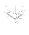
次に、図4に示すように、台板3上に固定されていた各第一支持脚4を、台板3から除去することで、基礎上に台板3を準備する(準備工程S2)。具体的には、各第一支持脚4の下端部4aと台板3との間が、例えば溶断等によって切断される。その後、複数の第一支持脚4が台板3上から撤去される。第一支持脚4が台板3上から除去された後に、台板3の第一支持脚4と接合されていた箇所が凹凸をなくすように研磨される。これにより、支持脚を支持する台板3の準備が完了する。この後、新設の圧縮機である第二圧縮機10の第二支持脚14及び第二圧縮機本体(回転機械本体)15(図8参照)を台板3上に設置する。
図8に示すように、第二支持脚14は、第一支持脚4と同様に、鉛直方向Dvに向かって延びている。第二支持脚14は、下端部14aから上端部14bに向かって鉛直方向Dvの上方に延びている。
第二圧縮機本体15は、第一圧縮機本体5と同様に、その外殻をなすケーシング15aと、ケーシング15aの外周面から外方に突出する被支持部15bと、を有している。
図5に示すように、第一支持脚4の除去後であって、後述するレベル調整部材配置工程S4の前に、台板3上の新設の支持脚である第二支持脚14を設置する箇所に、新設のライナー板(ライナー部材)16を設置する(ライナー部材配置工程S3)。ライナー板16は、矩形平板状をなしている。ライナー板16は、台板3と同じ鋼材で形成されている。ライナー板16は、後述する新設の圧縮機である第二圧縮機10の設置位置に配置される。ライナー板16の外周部16aが台板3の上面3fに溶接されることで、ライナー板16は台板3に対して一体に固定される。なお、ライナー板16は、台板3の第一支持脚4と接合されていた箇所上に重ねるように配置されてもよい。
次に、台板3上に、第二支持脚14の下端部14aの外形形状に沿って複数のレベル調整部材17を配置する(レベル調整部材配置工程S4)。本実施形態では、台板3に固定されたライナー板16上に、複数のレベル調整部材17が配置される。レベル調整部材17は、先端部17aに向かって高さ寸法が漸次縮小する楔形状をなしている。レベル調整部材17は、台板3と同じ鋼材で形成されている。複数のレベル調整部材17は、第二支持脚14の下端部14aの外形形状に沿って、周方向に均等に間隔をあけて配置されることが好ましい。また、各レベル調整部材17は、鉛直方向Dvの上方から見た際に、先端部17aを第二支持脚14の内側に向けて配置される。
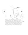
この後、新設の圧縮機である第二圧縮機10の第二支持脚14及び第二圧縮機本体(回転機械本体)15(図8参照)を載置する(載置工程S5)。具体的には、第二支持脚14を、複数のレベル調整部材17上に載置する。この際、レベル調整部材17の先端部17aが第二支持脚14とライナー板16との間に挟まれた状態となり、レベル調整部材17の一部が第二支持脚14から外側に飛び出した状態となる。
なお、第二支持脚14は、予め第二圧縮機本体15に一体に取り付けておいてもよく、第二支持脚14を台板3に対して固定した後に、第二支持脚14を第二圧縮機本体15と取り付けてもよい。第二支持脚14と第二圧縮機本体15とを予め一体にしておく場合、複数の第二支持脚14を取り付けた第二圧縮機本体15を吊り込み、各第二支持脚14を、ライナー板16上にセットされた複数のレベル調整部材17上に載せる。これにより、複数のレベル調整部材17は、ライナー板16と各第二支持脚14との間に介在することとなる。
次いで、図6に示すように、第二支持脚14の下端部14aへのレベル調整部材17の押し込み量を調整することで、第二圧縮機本体15の水平レベルを調整する(調整工程S6)。具体的には、各第二支持脚14において、レベル調整部材17を、ハンマー20等でライナー板16と第二支持脚14との間の奥に打ち込む。これにより、第二支持脚14の下端部14aに対するレベル調整部材17の押し込み量を調整する。レベル調整部材17が楔形状をなしていることで、押し込み量の調整によって、第二支持脚14の上端部14bの高さが調整される。その結果、第二支持脚14の上端部14b上に載置される第二圧縮機本体15の被支持部15bの高さが調整される。これにより、第二圧縮機本体15に設けられた回転軸(図示無し)が水平となるように、第二圧縮機本体15の水平レベル調整が行われる。
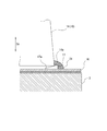
図7に示すように、調整工程S6後に、各第二支持脚14の下端部14aと、ライナー板16と、レベル調整部材17とを溶接する。これにより、第二支持脚14及びレベル調整部材17の台板3に対して位置を固定する(固定工程S7)。第二支持脚14の下端部14aとライナー板16とは、レベル調整部材17を巻き込むように第二支持脚14の下端部14aの全周にわたって連続して溶接される。これにより、第二支持脚14の下端部14aを周方向から覆うように溶接ビード(固定部)21が形成される。ライナー板16と各第二支持脚14との間に介在する複数のレベル調整部材17は、溶接ビード21によって、第二支持脚14と一体をなすようにライナー板16に接合される。
溶接ビード21は、第二支持脚14の下端部14aと複数のレベル調整部材17とが溶接されることで形成される。溶接ビード21は、ライナー板16を介して、第二支持脚14及びレベル調整部材17の台板3に対する位置を固定している。
これによって、図8に示すように、既設の第一圧縮機1を新設の第二圧縮機10に置き換えて設置することができる。したがって、第二圧縮機10は、台板3と、ライナー板16と、レベル調整部材17と、第二支持脚14と、溶接ビード21と、第二圧縮機本体15と、を備えている。
上述した実施形態の回転機械の設置方法、及び回転機械によれば、楔形状のレベル調整部材17の第二支持脚14の下端部14aへの押し込み量を調整することで、台板3に対する第二支持脚14の上端部14bの水平レベル調整を行うことができる。したがって、被支持部15bを介して第二支持脚14の上端部14bに固定されている第二圧縮機本体15の水平レベル調整を行うことができる。これにより、台板3に対する第二圧縮機本体15の水平度を容易かつ確実に調整することができる。したがって、台板3に対する第二支持脚14の位置を調整することで、第二圧縮機10の水平度を確保することができる。
また、台板3上に平板状のライナー板16が設けられ、複数のレベル調整部材17はライナー板16上に配置されている。そのため、台板3の上面が平滑でない場合であっても、レベル調整部材17を、平板状のライナー板16の平滑面上に配置することができる。したがって、台板3の状態に関わらず、レベル調整部材17の第二支持脚14の下方への押し込み量を調整する際に、レベル調整部材17を容易に移動させることができる。
また、既存の第一圧縮機本体5及び既存の第一支持脚4を除去した後、既存の第一支持脚4が固定されていた台板3を利用して、新設の第二圧縮機本体15及び第二支持脚14が設置されている。したがって、新たに圧縮機を設置する際に、台板3を設置し直す必要が無く、作業の効率化、及びコスト低減を図ることができる。
以上、本発明の実施形態について図面を参照して詳述したが、実施形態における各構成及びそれらの組み合わせ等は一例であり、本発明の趣旨から逸脱しない範囲内で、構成の付加、省略、置換、及びその他の変更が可能である。また、本発明は実施形態によって限定されることはなく、特許請求の範囲によってのみ限定される。
例えば、上記実施形態では、既設の第一圧縮機1を新設の第二圧縮機10に置き換える場合を例に挙げたが、これに限られるものではない。例えば、第一圧縮機1が無い場所に、新設の第二圧縮機10を設置する場合であっても、本発明を適用することが可能である。この場合、台板3を準備する工程では、台板3を基礎上に新たに設置すればよい。
また、上記実施形態では、回転機械として、圧縮機を例示したが、これに限らず、各種のタービンや電動機等の回転機械であっても、本発明の回転機械の設置方法を適用可能である。
上記した回転機械の設置方法、及び回転機械によれば、台板に対する支持脚の位置を調整することで、回転機械の水平度を確保することができる。
1 第一圧縮機(回転機械)
2 基礎
3 台板
3f 上面
4 第一支持脚(支持脚)
4a 下端部
4b 上端部
5 第一圧縮機本体(回転機械本体)
5a ケーシング
5b 被支持部
10 第二圧縮機(回転機械)
14 第二支持脚(支持脚)
14a 下端部
14b 上端部
15 第二圧縮機本体(回転機械本体)
16 ライナー板(ライナー部材)
16a 外周部
17 レベル調整部材
17a 先端部
20 ハンマー
21 溶接ビード(固定部)
S1 圧縮機本体除去工程
S2 準備工程
S3 ライナー部材配置工程
S4 レベル調整部材配置工程
S5 載置工程
S6 調整工程
S7 固定工程
2 基礎
3 台板
3f 上面
4 第一支持脚(支持脚)
4a 下端部
4b 上端部
5 第一圧縮機本体(回転機械本体)
5a ケーシング
5b 被支持部
10 第二圧縮機(回転機械)
14 第二支持脚(支持脚)
14a 下端部
14b 上端部
15 第二圧縮機本体(回転機械本体)
16 ライナー板(ライナー部材)
16a 外周部
17 レベル調整部材
17a 先端部
20 ハンマー
21 溶接ビード(固定部)
S1 圧縮機本体除去工程
S2 準備工程
S3 ライナー部材配置工程
S4 レベル調整部材配置工程
S5 載置工程
S6 調整工程
S7 固定工程
Claims (4)
- 鉛直方向に延びる複数の支持脚と、前記支持脚の上端部に固定された回転機械本体とを備えた回転機械の設置方法であって、
基礎上に、前記支持脚を支持する台板を準備する準備工程と、
前記台板上に、前記支持脚の下端部の外形形状に沿って複数の楔形状をなすレベル調整部材を配置するレベル調整部材配置工程と、
前記支持脚を、複数の前記レベル調整部材上に載置する載置工程と、
前記支持脚の下端部への前記レベル調整部材の押し込み量を調整することで、前記回転機械本体の水平レベルを調整する調整工程と、
前記支持脚と複数の前記レベル調整部材とを溶接して、前記支持脚及び前記レベル調整部材の前記台板に対する位置を固定する固定工程と、を含む回転機械の設置方法。 - レベル調整部材配置工程の前に、前記台板上に平板状のライナー部材を配置するライナー部材配置工程をさらに備え、
前記レベル調整部材配置工程では、複数の前記レベル調整部材は前記台板に固定された前記ライナー部材上に配置され、
前記固定工程では、前記支持脚及び複数の前記レベル調整部材は、前記ライナー部材に溶接される請求項1に記載の回転機械の設置方法。 - 前記準備工程は、前記台板上に固定されていた既存の支持脚を前記台板から除去する請求項1または請求項2に記載の回転機械の設置方法。
- 基礎上に設置された台板と、
前記台板上に設けられた複数の楔形状のレベル調整部材と、
複数の前記レベル調整部材上に載置され、鉛直方向に向かって延びる複数の支持脚と、
前記支持脚の下端部と複数の前記レベル調整部材とが溶接されることで形成され、前記支持脚及び前記レベル調整部材の前記台板に対する位置を固定する固定部と、
複数の前記支持脚に支持された回転機械本体と、を備える回転機械。
Priority Applications (3)
| Application Number | Priority Date | Filing Date | Title |
|---|---|---|---|
| JP2018555388A JP6706344B2 (ja) | 2016-12-07 | 2016-12-07 | 回転機械の設置方法、及び回転機械 |
| PCT/JP2016/086413 WO2018105065A1 (ja) | 2016-12-07 | 2016-12-07 | 回転機械の設置方法、及び回転機械 |
| US16/321,273 US11060258B2 (en) | 2016-12-07 | 2016-12-07 | Method for installing rotary machine, and rotary machine |
Applications Claiming Priority (1)
| Application Number | Priority Date | Filing Date | Title |
|---|---|---|---|
| PCT/JP2016/086413 WO2018105065A1 (ja) | 2016-12-07 | 2016-12-07 | 回転機械の設置方法、及び回転機械 |
Publications (1)
| Publication Number | Publication Date |
|---|---|
| WO2018105065A1 true WO2018105065A1 (ja) | 2018-06-14 |
Family
ID=62490906
Family Applications (1)
| Application Number | Title | Priority Date | Filing Date |
|---|---|---|---|
| PCT/JP2016/086413 Ceased WO2018105065A1 (ja) | 2016-12-07 | 2016-12-07 | 回転機械の設置方法、及び回転機械 |
Country Status (3)
| Country | Link |
|---|---|
| US (1) | US11060258B2 (ja) |
| JP (1) | JP6706344B2 (ja) |
| WO (1) | WO2018105065A1 (ja) |
Citations (3)
| Publication number | Priority date | Publication date | Assignee | Title |
|---|---|---|---|---|
| JPS60255656A (ja) * | 1984-05-31 | 1985-12-17 | 電気化学工業株式会社 | セメント質機械据え付け用ライナ−プレ−ト |
| JPH04155015A (ja) * | 1990-10-18 | 1992-05-28 | Misawa Homes Co Ltd | 住宅の基礎施工方法 |
| JPH05339951A (ja) * | 1992-06-05 | 1993-12-21 | Misawa Homes Co Ltd | プレキャストコンクリート製基礎 |
Family Cites Families (4)
| Publication number | Priority date | Publication date | Assignee | Title |
|---|---|---|---|---|
| US3604306A (en) * | 1969-08-07 | 1971-09-14 | Gordon G Denholm | Adjustable mounting shim |
| US4592532A (en) | 1983-11-14 | 1986-06-03 | Stith Jr M Randall | Expansible support and method of use |
| JP4363799B2 (ja) * | 2001-06-08 | 2009-11-11 | 株式会社東芝 | タービン組立輸送架台および同架台を用いたタービン組立方法、輸送方法 |
| JP2016075194A (ja) | 2014-10-03 | 2016-05-12 | 三菱重工業株式会社 | 支持構造、車室、および回転機械 |
-
2016
- 2016-12-07 US US16/321,273 patent/US11060258B2/en active Active
- 2016-12-07 JP JP2018555388A patent/JP6706344B2/ja active Active
- 2016-12-07 WO PCT/JP2016/086413 patent/WO2018105065A1/ja not_active Ceased
Patent Citations (3)
| Publication number | Priority date | Publication date | Assignee | Title |
|---|---|---|---|---|
| JPS60255656A (ja) * | 1984-05-31 | 1985-12-17 | 電気化学工業株式会社 | セメント質機械据え付け用ライナ−プレ−ト |
| JPH04155015A (ja) * | 1990-10-18 | 1992-05-28 | Misawa Homes Co Ltd | 住宅の基礎施工方法 |
| JPH05339951A (ja) * | 1992-06-05 | 1993-12-21 | Misawa Homes Co Ltd | プレキャストコンクリート製基礎 |
Also Published As
| Publication number | Publication date |
|---|---|
| US20190161934A1 (en) | 2019-05-30 |
| JP6706344B2 (ja) | 2020-06-03 |
| US11060258B2 (en) | 2021-07-13 |
| JPWO2018105065A1 (ja) | 2019-06-24 |
Similar Documents
| Publication | Publication Date | Title |
|---|---|---|
| JP4660476B2 (ja) | 研磨エレメント及び研磨プレートを保持する支持プレート | |
| MX2016007161A (es) | Pedestal de adoquin y metodo para instalar el mismo. | |
| JP7034890B2 (ja) | 杭体の打設方法 | |
| KR20160002017A (ko) | 실린더 피스톤의 패킹 조립장치 | |
| JP2014224421A (ja) | シールドトンネルの補強構造及び補強方法 | |
| JP2015183688A (ja) | ターボ機械から内側ハウジングを取り外す工具 | |
| JP6706344B2 (ja) | 回転機械の設置方法、及び回転機械 | |
| JP5003192B2 (ja) | タンク底板の取替方法 | |
| JP2012104786A (ja) | 太陽光発電モジュールの設置構造 | |
| US11268648B2 (en) | Supporting platform, rotating machine unit, and method for manufacturing rotating machine unit | |
| KR101800342B1 (ko) | 보빈용 플랜지 제조장치 | |
| JP3157137U (ja) | 受枠設置用吊り具 | |
| JP6562544B2 (ja) | 円筒状ケーソンの足場 | |
| JP2016113775A (ja) | 杭受け台装置 | |
| JP4296546B2 (ja) | 柱建方用治具 | |
| JP6361201B2 (ja) | 杭保持装置 | |
| JP2006152669A (ja) | 滑り支承免震構造物の建築構法 | |
| JP3179164U (ja) | 足場板 | |
| JP6029856B2 (ja) | トンネル防水工法における充填材及び覆工コンクリートの打設装置 | |
| JP3223890U (ja) | 位置決め用治具 | |
| JP6368839B2 (ja) | 免震装置の取付方法 | |
| KR101404592B1 (ko) | 피스톤헤드의 강성 증대방법 및 그 장치 | |
| JP5322708B2 (ja) | 電柱の移設方法 | |
| JP2015124479A (ja) | 免震装置取付プレート、及び免震装置の取付方法 | |
| JP7047681B2 (ja) | 回転電機の仮固定治具及びこれを使用する回転電機の組立方法 |
Legal Events
| Date | Code | Title | Description |
|---|---|---|---|
| 121 | Ep: the epo has been informed by wipo that ep was designated in this application |
Ref document number: 16923399 Country of ref document: EP Kind code of ref document: A1 |
|
| ENP | Entry into the national phase |
Ref document number: 2018555388 Country of ref document: JP Kind code of ref document: A |
|
| NENP | Non-entry into the national phase |
Ref country code: DE |
|
| 122 | Ep: pct application non-entry in european phase |
Ref document number: 16923399 Country of ref document: EP Kind code of ref document: A1 |