WO2018088261A1 - 給紙アダプター - Google Patents
給紙アダプター Download PDFInfo
- Publication number
- WO2018088261A1 WO2018088261A1 PCT/JP2017/039126 JP2017039126W WO2018088261A1 WO 2018088261 A1 WO2018088261 A1 WO 2018088261A1 JP 2017039126 W JP2017039126 W JP 2017039126W WO 2018088261 A1 WO2018088261 A1 WO 2018088261A1
- Authority
- WO
- WIPO (PCT)
- Prior art keywords
- sheet
- paper feed
- base plate
- plate portion
- width
- Prior art date
- Legal status (The legal status is an assumption and is not a legal conclusion. Google has not performed a legal analysis and makes no representation as to the accuracy of the status listed.)
- Ceased
Links
Images



Classifications
-
- B—PERFORMING OPERATIONS; TRANSPORTING
- B65—CONVEYING; PACKING; STORING; HANDLING THIN OR FILAMENTARY MATERIAL
- B65H—HANDLING THIN OR FILAMENTARY MATERIAL, e.g. SHEETS, WEBS, CABLES
- B65H1/00—Supports or magazines for piles from which articles are to be separated
- B65H1/04—Supports or magazines for piles from which articles are to be separated adapted to support articles substantially horizontally, e.g. for separation from top of pile
-
- B—PERFORMING OPERATIONS; TRANSPORTING
- B65—CONVEYING; PACKING; STORING; HANDLING THIN OR FILAMENTARY MATERIAL
- B65H—HANDLING THIN OR FILAMENTARY MATERIAL, e.g. SHEETS, WEBS, CABLES
- B65H1/00—Supports or magazines for piles from which articles are to be separated
- B65H1/26—Supports or magazines for piles from which articles are to be separated with auxiliary supports to facilitate introduction or renewal of the pile
- B65H1/266—Support fully or partially removable from the handling machine, e.g. cassette, drawer
-
- B—PERFORMING OPERATIONS; TRANSPORTING
- B65—CONVEYING; PACKING; STORING; HANDLING THIN OR FILAMENTARY MATERIAL
- B65H—HANDLING THIN OR FILAMENTARY MATERIAL, e.g. SHEETS, WEBS, CABLES
- B65H1/00—Supports or magazines for piles from which articles are to be separated
- B65H1/28—Supports or magazines for piles from which articles are to be separated compartmented to receive piles side-by-side
-
- B—PERFORMING OPERATIONS; TRANSPORTING
- B65—CONVEYING; PACKING; STORING; HANDLING THIN OR FILAMENTARY MATERIAL
- B65H—HANDLING THIN OR FILAMENTARY MATERIAL, e.g. SHEETS, WEBS, CABLES
- B65H2402/00—Constructional details of the handling apparatus
- B65H2402/30—Supports; Subassemblies; Mountings thereof
- B65H2402/32—Sliding support means
-
- B—PERFORMING OPERATIONS; TRANSPORTING
- B65—CONVEYING; PACKING; STORING; HANDLING THIN OR FILAMENTARY MATERIAL
- B65H—HANDLING THIN OR FILAMENTARY MATERIAL, e.g. SHEETS, WEBS, CABLES
- B65H2405/00—Parts for holding the handled material
- B65H2405/30—Other features of supports for sheets
- B65H2405/32—Supports for sheets partially insertable - extractable, e.g. upon sliding movement, drawer
- B65H2405/324—Supports for sheets partially insertable - extractable, e.g. upon sliding movement, drawer between operative position and non operative position
-
- B—PERFORMING OPERATIONS; TRANSPORTING
- B65—CONVEYING; PACKING; STORING; HANDLING THIN OR FILAMENTARY MATERIAL
- B65H—HANDLING THIN OR FILAMENTARY MATERIAL, e.g. SHEETS, WEBS, CABLES
- B65H2405/00—Parts for holding the handled material
- B65H2405/30—Other features of supports for sheets
- B65H2405/33—Compartmented support
- B65H2405/332—Superposed compartments
-
- B—PERFORMING OPERATIONS; TRANSPORTING
- B65—CONVEYING; PACKING; STORING; HANDLING THIN OR FILAMENTARY MATERIAL
- B65H—HANDLING THIN OR FILAMENTARY MATERIAL, e.g. SHEETS, WEBS, CABLES
- B65H2511/00—Dimensions; Position; Numbers; Identification; Occurrences
- B65H2511/10—Size; Dimensions
-
- B—PERFORMING OPERATIONS; TRANSPORTING
- B65—CONVEYING; PACKING; STORING; HANDLING THIN OR FILAMENTARY MATERIAL
- B65H—HANDLING THIN OR FILAMENTARY MATERIAL, e.g. SHEETS, WEBS, CABLES
- B65H2511/00—Dimensions; Position; Numbers; Identification; Occurrences
- B65H2511/10—Size; Dimensions
- B65H2511/12—Width
-
- B—PERFORMING OPERATIONS; TRANSPORTING
- B65—CONVEYING; PACKING; STORING; HANDLING THIN OR FILAMENTARY MATERIAL
- B65H—HANDLING THIN OR FILAMENTARY MATERIAL, e.g. SHEETS, WEBS, CABLES
- B65H2801/00—Application field
- B65H2801/03—Image reproduction devices
- B65H2801/06—Office-type machines, e.g. photocopiers
Definitions
- the present invention is mounted in a sheet feeding cassette having a pair of first regulating plate portions that regulate the position in the width direction of sheets of a predetermined size stacked in a bundle, and has a small width smaller than the sheet of the predetermined size.
- the present invention relates to a paper feed adapter that enables a sheet of a size to be used.
- a paper feed adapter that is mounted on a paper feed cassette that stores sheets of a predetermined size and that can use sheets of a size different from the predetermined size is known (see, for example, Patent Document 1).
- a sheet placement surface is formed in a curved shape so that a long size sheet having a longer dimension in the paper feeding direction than a predetermined size sheet can be fed.
- the paper feed adapter is used by being placed on a substrate provided in a paper feed cassette. This substrate is used to set a sheet of a predetermined size.
- the user takes out a sheet of a predetermined size set on the substrate out of the sheet feeding cassette and fixes the sheet feeding adapter on the substrate.
- a pair of regulating plate portions are provided on the cassette bottom surface of the sheet feeding cassette described above to regulate the position in the width direction of a sheet of a predetermined size set on the substrate.
- this paper feed cassette it is not possible to use a sheet having a small width that is smaller than a sheet having a predetermined size. For this reason, it is necessary for the user to purchase a dedicated sheet feeding cassette in which the interval between the regulating plate portions is changed.
- there is a problem that purchasing a dedicated sheet feeding cassette to use a small-sized sheet that is rarely used places a large burden on the user in terms of cost.
- space efficiency is reduced as the number of paper feed cassettes is increased.
- the present invention has been made in view of the above points, and an object of the present invention is to make it possible to use a sheet having a small width different from a predetermined size by a simple operation without causing a user to feel bothered.
- the purpose is to provide a paper feeding adapter at a low cost.
- the paper feed adapter according to the present invention is mounted in a paper feed cassette having a pair of first regulating plate portions that regulate the position in the width direction of a predetermined size of sheets stacked in a bundle, and is more than the predetermined size of sheets.
- a sheet having a small width and a small width can be used.
- the sheet bundle is placed on the upper surface of the sheet bundle of the predetermined size set in the sheet feeding cassette and guided by the pair of first regulating plate portions so as to be movable in the sheet feeding direction.
- a base plate portion on which a sheet of a size is set, and a pair of second plates that stand up from the upper surface of the base plate portion and regulate the position in the width direction of the small-sized sheet bundle set on the upper surface of the base plate portion A restriction plate portion, and the base plate portion includes a sheet feeding position where a small-width sheet bundle set on the base plate portion is positioned below a predetermined sheet-feeding member, and the narrow-width sheet bundle It is configured to be movable to a retracted position located on the rear side in the paper feeding direction with respect to the predetermined paper feeding member.
- an inexpensive sheet feeding adapter that allows a user to use a sheet having a small width different from a predetermined size by a simple operation without causing a user to feel bothersome.
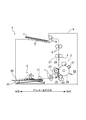
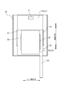
- FIG. 1 is a schematic diagram illustrating an overall configuration of an image forming apparatus including a paper feed cassette having a paper feed adapter mounted therein.
- FIG. 2 is a plan view showing a schematic configuration of the paper feed cassette.
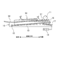
- FIG. 3 is a side view schematically showing the paper feed mechanism.
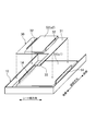
- FIG. 4 is a perspective view separately showing a paper feed cassette and a paper feed adapter attached to the paper feed cassette.
- FIG. 5 is a plan view of the paper feed adapter.
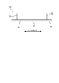
- FIG. 6 is a side view of the paper feeding adapter as seen from the rear side in the paper feeding direction.
- FIG. 7 is a plan view showing a state where the paper feed adapter is at the paper feed position.
- FIG. 8 is a plan view showing a state where the paper feed adapter is in the retracted position.
- FIG. 1 shows an image forming apparatus 1 according to the present embodiment.
- the image forming apparatus 1 is a monochrome laser printer in this embodiment.
- the image forming apparatus 1 includes a paper feeding unit 2, an image forming unit 3, a fixing unit 4, a paper discharge unit 5, and a housing 6.
- a plurality of transport roller pairs 7 to 9 that sandwich and transport a sheet s are disposed on the sheet transport path from the paper feed unit 2 to the paper discharge unit 5.
- the paper feeding unit 2 is disposed in the lower part of the housing 6.
- the paper feed unit 2 includes a paper feed cassette 10 in which the sheets s are stored, and a pickup roller 11 for taking out the sheets s in the paper feed cassette 10 and sending them out of the cassette.
- the pickup roller 11 is configured separately from the paper feed cassette 10 and is fixed to the housing 6.
- the sheet s sent out of the cassette from the paper feed cassette 10 is supplied to the image forming unit 3 via the conveyance roller pair 7.
- the image forming unit 3 includes a photosensitive drum 20, a charger 21, an exposure device 22, a developing device 23, a transfer device 24, and a toner container (not shown).
- the peripheral surface of the photosensitive drum 20 is charged by the charger 21, and then the original image data (for example, image data of the original image received from the external terminal) is applied to the surface of the photosensitive drum 20 by the exposure device 22.
- the original image data for example, image data of the original image received from the external terminal
- the electrostatic latent image formed (supported) on the surface of the photosensitive drum 20 is developed as a toner image by the developing device 23.
- the toner image developed by the developing device 23 is transferred to the sheet s supplied from the paper feeding unit 2 by the transfer device 24.
- the sheet s after the transfer is supplied to the fixing unit 4 by the transfer roller 25 and the photosensitive drum 20 of the transfer unit 24.
- the fixing unit 4 includes a heating roller 26 and a pressure roller 27 that is pressed against the heating roller 26 with a predetermined pressing load. Inside the heating roller 26, a halogen lamp (not shown) as heating means is arranged. The peripheral surface of the heating roller 26 is heated by the heat generated from the halogen lamp.
- the fixing unit 4 presses and heats the sheet s supplied from the image forming unit 3 between the heating roller 26 and the pressure roller 27, thereby fixing the toner image on the sheet s. Then, the sheet s on which the toner image is fixed by the fixing unit 4 is sent out to the downstream side by the heating roller 26 and the pressure roller 27. The fed sheet s is discharged to a paper discharge unit 5 formed on the upper surface of the housing 6 by a plurality of conveying roller pairs 7-9.
- the paper feeding cassette 10 is inserted into the paper feeding unit 2 in the image forming apparatus 1 through a cassette insertion opening formed at the lower end of the side surface of the image forming apparatus 1.
- a sheet bundle S1 made of sheets s1 of a predetermined size specified in advance and a sheet bundle S2 made of sheets s2 of a small width size smaller than the sheet s1 of the predetermined size can be accommodated. It has become.
- the predetermined size is, for example, A4 size
- the small width size is, for example, A5 size.
- the sheet bundle S1 having a predetermined size is directly set on the sheet feeding cassette 10, while the sheet bundle S2 having a small width is set on the sheet feeding cassette 10 via the sheet feeding adapter 30. Details of the paper feed adapter 30 will be described later.
- the paper feed cassette 10 has a rectangular box shape opened to the front side and the upper side in the paper feed direction.
- a lift plate 13 on which a sheet bundle S1 of a predetermined size is placed is disposed on the upper surface.
- a pair of width restricting plates (first restricting plate portions) 14 for restricting the position in the width direction of the sheet bundle S1 of a predetermined size are erected on the cassette bottom surface of the sheet feeding cassette 10.
- the pair of width restricting plates 14 are arranged at an interval in the sheet width direction. The distance between the pair of width regulating plates 14 is set to be equal to the width size of the sheet s1 having a predetermined size.
- One end of the lift plate 13 (left end in FIG. 3) is pivotally supported by a shaft 15 on the cassette bottom side.
- a shaft 17 is disposed in parallel with the shaft 15 on the cassette bottom surface side of the paper feed cassette 10, and one end of the lever 16 (the right end in FIG. 3) is connected to the shaft 17 so as to rotate together.
- the other end (left end in FIG. 3) of the lever 16 is in contact with the other end (right end in FIG. 3) of the lift plate 13 from below.
- FIG. 5 is a plan view of the paper feed adapter 30, and FIG. 6 is a side view of the paper feed adapter 30 as seen from the paper feed direction.
- the paper feed adapter 30 has a base plate portion 31, a pair of restriction plate portions (second restriction plate portions) 32, and a handle portion 33.
- the paper feed adapter 30 is formed of thick paper such as cardboard, for example.
- the paper feed adapter 30 may be made of, for example, resin or metal.
- the base plate portion 31 has a rectangular plate shape, and is placed on the upper surface (the upper surface of the uppermost sheet s1) of a sheet bundle S1 of a predetermined size set in the sheet feeding cassette 10. On the upper surface of the base plate portion 31, a sheet bundle S2 having a small width is set.
- the length of the base plate portion 31 in the sheet width direction is set to be equal (same or slightly smaller) than the interval between the pair of width regulating plates 14 rising from the cassette bottom surface of the sheet feeding cassette 10.
- the length of the base plate portion 31 in the paper feeding direction is sufficiently smaller than the length of the paper feeding cassette 10 in the paper feeding direction.
- the base plate portion 31 is guided by the pair of width regulating plates 14 and can slide (slide) on the upper surface of the sheet bundle S1 in the sheet feeding direction.
- a low friction layer 34 is formed on the lower surface of the base plate portion 31 to reduce the frictional force acting on the lower surface from the upper surface of the sheet bundle S1.
- the friction coefficient of the low friction layer 34 with respect to the sheet s1 is smaller than the friction coefficient of the material of the base plate portion 31 with respect to the sheet s1.
- the low friction layer 34 is formed, for example, by applying a coating process to the lower surface of the base plate portion 31.
- the pair of restricting plate portions 32 are erected from the upper surface of the base plate portion 31 and are arranged at intervals in the sheet width direction.
- the pair of restricting plate portions 32 are fixed to the upper surface of the base plate portion 31 with an adhesive or the like.
- the interval between the pair of restricting plate portions 32 restricts the position in the width direction of the sheet bundle S2 having a small width placed on the upper surface of the base plate portion 31. What is the distance between the pair of restricting plate portions 32? It is set to be equal to (same as or slightly smaller than) the width size of the small-size sheet s2.
- the handle portion 33 extends in a band shape from the front end of the base plate portion 31 in the paper feeding direction toward the front side.
- the handle portion 33 is connected to one end portion of the base plate portion 31 in the sheet width direction.
- the handle portion 33 has a width that allows the user to hold it with a hand.
- the base plate portion 31 can move between a paper feeding position (position in FIG. 7) and a retreat position (position in FIG. 8) by sliding in the paper feeding direction.
- the front end position of the base plate portion 31 substantially coincides with the front end position of the paper feed cassette 10, and the front end portion of the small-width sheet bundle S ⁇ b> 2 set on the base plate portion 31 is the pickup roller 11.
- the pickup roller predetermined sheet feeding member
- the rear end of the base plate portion 31 is retracted to the vicinity of the rear end of the sheet feeding cassette 10, and the front end portion of the small-width sheet bundle S2 set on the base plate portion 31 is removed from the pickup roller 11. Also moves to the rear side in the paper feeding direction. As a result, the upper surface of the sheet bundle S1 of a predetermined size set on the lower side of the paper feeding adapter 30 is exposed. Therefore, when the lift plate 13 in the sheet feeding cassette 10 is lifted up, the uppermost surface of the small-sized sheet bundle S2 does not come into contact with the pickup roller 11, while the upper surface of the predetermined-size sheet bundle S1 is the pickup roller 11. Abut. Therefore, in the retracted position, the sheet s2 having a small width cannot be fed, while the sheet s1 having a predetermined size can be fed by the pickup roller 11.
- the handle portion 33 protrudes outside the image forming apparatus 1 from a gap formed between the cassette insertion opening on the side surface of the image forming apparatus 1 and the side wall of the sheet feeding cassette 10.
- the handle portion 33 has such a length that the rear end portion of the handle portion 33 protrudes outside the paper feed cassette 10 (outside the image forming apparatus 1) even when the paper feed adapter 30 is in the paper feed position. (See FIG. 7).
- the handle 33 is configured to be flexible in an arch shape when viewed from the sheet width direction.
- the handle portion 33 has flexibility in the thickness direction. As a result, even if the thickness of the sheet bundle S1 of a predetermined size set in the sheet feeding cassette 10 decreases (the remaining number of sheets s1 decreases), the handle portion 33 bends in an arch shape, so that the base plate portion 31 does not lift from the upper surface of the sheet bundle S1.
- the paper feed adapter 30 is simply placed on the upper surface of the sheet bundle S1 of a predetermined size set in the paper feed cassette 10, and has a small width smaller than the predetermined size.
- the sheet bundle S2 can be fed to the image forming unit 3. Accordingly, it is not necessary to separately add the sheet feeding cassette 10 in order to set the sheet bundle S2 having a small width size, so that space can be saved. Further, since the configuration of the paper feed adapter 30 is simpler than that of the paper feed cassette 10, the cost can be reduced as compared with the case where the paper feed cassette 10 is purchased separately.
- the sheet feeding adapter 30 can be mounted while the sheet bundle S1 of a predetermined size is set in the sheet cassette 10, the user can use the sheet bundle S2 in order to use the sheet bundle S2 having a small width. There is no need to take out the bundle S1 or return the sheet bundle S1 of a predetermined size into the sheet feeding cassette 10 after the use of the small width sheet bundle S2. Therefore, it is possible to reduce a burden on the user when the user uses the sheet bundle S2 having a small width, thereby reducing the user's annoyance.
- a handle portion 33 that can be gripped by the user extends from the base plate portion 31 of the paper feed adapter 30, the user can easily move the base plate portion 31 in the paper feed direction via the handle portion 33. Can be slid.
- a low friction layer 34 having a smaller coefficient of friction with respect to the upper surface (sheet s1) of the sheet bundle S1 than the material constituting the base plate portion 31 is formed on the lower surface of the base plate portion 31 of the paper feed adapter 30. Accordingly, when the base plate portion 31 is moved between the paper feed position and the retracted position, the friction force acting on the base plate portion 31 is reduced as much as possible from the upper surface of the sheet bundle S1, and the paper feed adapter 30 is moved smoothly. be able to.
- the restriction plate portion 32 is fixed to the base plate portion 31 with an adhesive, but the present invention is not limited to this, and the base plate portion 31, the restriction plate portion 32, and the handle portion 33 are not limited thereto.
- the regulation plate portion 32 may be formed by bending a thick paper and polymerizing it in the sheet width direction.
- the position of the pair of width restricting plates 14 rising from the cassette bottom surface of the sheet feeding cassette 10 is fixed.
- the present invention is not limited to this.
- a pair of width restricting plates using a rack and pinion mechanism is used.
- the position of the plate 14 in the sheet width direction may be adjustable.
- the sheet of a predetermined size means a minimum width sheet among a plurality of types of sheets that can be accommodated by moving the pair of width regulating plates 14, and the small width sheet is smaller than the minimum width. It means a sheet of width size.
- the image forming apparatus 1 is a laser printer.
- the present invention is not limited to this, and the image forming apparatus 1 may be a copier, a multifunction peripheral (MFP), a facsimile, or the like. .
- the present invention is useful for a paper feed adapter.
Landscapes
- Engineering & Computer Science (AREA)
- Mechanical Engineering (AREA)
- Sheets, Magazines, And Separation Thereof (AREA)
Abstract
給紙アダプター(30)は、給紙カセット(10)内にセットされた所定サイズのシート束(S1)の上面に載置され且つ一対の第一規制板(14)によりガイドされて給紙方向に移動可能に構成され、上面に小幅サイズのシートがセットされるベース板部(31)と、該ベース板部(31)の上面から起立し、当該ベース板部(31)の上面にセットされた小幅サイズのシート束(S2)の幅方向の位置を規制する一対の第二規制板部(32)とを備え、ベース板部(31)は、小幅サイズのシート(S2)を給紙可能な給紙位置と、給紙位置よりも給紙方向の後側に位置する退避位置とに移動可能に構成されている。
Description
本発明は、束状に重ねた所定サイズのシートの幅方向の位置を規制する一対の第一規制板部を有する給紙カセット内に装着され、当該所定サイズのシートよりも幅サイズが小さい小幅サイズのシートを使用可能にする給紙アダプターに関する。
従来より、所定サイズのシートが収容される給紙カセットに装着され、該所定サイズとは異なるサイズのシートを使用可能にする給紙アダプターは知られている(例えば、特許文献1参照)。この給紙アダプターは、所定サイズのシートよりも給紙方向の寸法が長い長尺サイズのシートを給紙可能にするためにシート載置面が曲面状に形成されている。給紙アダプターは、給紙カセット内に設けられた基板に載置されて使用される。この基板は所定サイズのシートをセットするために使用される。ユーザーは、長尺サイズのシートを使用する際には、基板上にセットされた所定サイズのシートを給紙カセット外に取り出して当該基板上に給紙アダプターを固定する。
上述した給紙カセットのカセット底面には、基板にセットされた所定サイズのシートの幅方向の位置を規制するべく一対の規制板部が設けられる場合がある。この給紙カセットでは、所定サイズのシートよりも幅サイズが小さい小幅サイズのシートを使用することができない。このため,ユーザーは、規制板部の間隔を変更した専用の給紙カセットを別途購入する必要がある。しかし、滅多に使用しない小幅サイズのシートを使用するために専用の給紙カセットを購入することはコスト面でのユーザー負担が大きいという問題がある。また給紙カセットを増設することに伴いスペース効率の低下を招いてしまう。
そこで、上述した特許文献1に示すような給紙アダプターを利用して小幅サイズのシートを給紙カセットにセットすることが考えられる。しかし、この給紙アダプターでは、小幅サイズのシートを使用する際に、給紙カセット内のシートを一旦、給紙カセット外に取り出してから給紙アダプターを基板上にセットし、小幅サイズのシートの使用が終わると該給紙アダプターを取り外して給紙カセット内にシートを再度戻す必要がある。このため、ユーザーにとって給紙アダプターの交換作業が煩わしいという問題がある。
本発明は、かかる点に鑑みてなされたものであり、その目的とするところは、ユーザーに煩わしさ感を生じさせることなく簡単な作業で所定サイズとは異なる小幅サイズのシートを使用可能にする給紙アダプターを安価に提供しようとすることにある。
本発明に係る給紙アダプターは、束状に重ねた所定サイズのシートの幅方向の位置を規制する一対の第一規制板部を有する給紙カセット内に装着され、当該所定サイズのシートよりも幅サイズが小さい小幅サイズのシートを使用可能にするものである。
そして、上記給紙カセット内にセットされた上記所定サイズのシート束の上面に載置され且つ上記一対の第一規制板部によりガイドされて給紙方向に移動可能に構成され、上面に上記小幅サイズのシートがセットされるベース板部と、上記ベース板部の上面から起立し、当該ベース板部の上面にセットされた上記小幅サイズのシート束の幅方向の位置を規制する一対の第二規制板部とを備え、上記ベース板部は、該ベース板部にセットされた小幅サイズのシート束が所定の給紙部材の下側に位置する給紙位置と、該小幅サイズのシート束が上記所定の給紙部材よりも給紙方向の後側に位置する退避位置とに移動可能に構成されている。
本発明によれば、ユーザーに煩わしさ感を生じさせることなく簡単な作業で所定サイズとは異なる小幅サイズのシートを使用可能にする給紙アダプターが安価に提供される。
以下、本発明の実施形態を図面に基づいて詳細に説明する。尚、本発明は、以下の実施形態に限定されるものではない。
《実施形態》
図1は、本実施形態における画像形成装置1を示している。画像形成装置1は、本実施形態ではモノクロレーザープリンターからなる。
この画像形成装置1は、給紙部2、作像部3、定着部4、排紙部5、及び筐体6を有している。給紙部2から排紙部5に至るシート搬送経路には、シートs(例えばOHPシートや記録紙等)を挟持して搬送する複数の搬送ローラー対7~9が配置されている。上記給紙部2は、筐体6内の下部に配置されている。給紙部2は、シートsが収容される給紙カセット10と、該給紙カセット10内のシートsを取り出して該カセット外に送り出すためのピックアップローラー11とを有している。ピックアップローラー11は給紙カセット10とは別体で構成されて筐体6に固定されている。給紙カセット10よりカセット外に送り出されたシートsは、搬送ローラー対7を介して作像部3に供給される。
図1は、本実施形態における画像形成装置1を示している。画像形成装置1は、本実施形態ではモノクロレーザープリンターからなる。
この画像形成装置1は、給紙部2、作像部3、定着部4、排紙部5、及び筐体6を有している。給紙部2から排紙部5に至るシート搬送経路には、シートs(例えばOHPシートや記録紙等)を挟持して搬送する複数の搬送ローラー対7~9が配置されている。上記給紙部2は、筐体6内の下部に配置されている。給紙部2は、シートsが収容される給紙カセット10と、該給紙カセット10内のシートsを取り出して該カセット外に送り出すためのピックアップローラー11とを有している。ピックアップローラー11は給紙カセット10とは別体で構成されて筐体6に固定されている。給紙カセット10よりカセット外に送り出されたシートsは、搬送ローラー対7を介して作像部3に供給される。
作像部3は、感光体ドラム20、帯電器21、露光装置22、現像装置23、転写器24、及びトナーコンテナ(図示省略)を有している。作像部3では、帯電器21によって感光体ドラム20の周面を帯電させた後、露光装置22によって感光体ドラム20の表面に原稿画像データ(例えば、外部端末より受信した原稿画像の画像データ)に基づくレーザー光を照射することで静電潜像を形成する。感光体ドラム20の表面に形成(担持)された静電潜像は、現像装置23によりトナー像として現像される。現像装置23によって現像されたトナー像は、転写器24によって、給紙部2から供給されるシートsに対して転写される。該転写後のシートsは、転写器24の転写ローラー25と感光体ドラム20とよって定着部4に供給される。
定着部4は、加熱ローラー26と、該加熱ローラー26に対して所定の圧接荷重で圧接される加圧ローラー27とを有している。加熱ローラー26の内側には加熱手段であるハロゲンランプ(図示省略)が配置されている。このハロゲンランプから発せられた熱により加熱ローラー26の周面が加熱される。
定着部4は、上記作像部3より供給されるシートsを加熱ローラー26及び加圧ローラー27間で加圧及び加熱することにより、当該シートsにトナー像を定着させる。そして、定着部4にてトナー像が定着されたシートsは、加熱ローラー26及び加圧ローラー27により下流側へと送り出される。この送り出されたシートsは、複数の搬送ローラー対7~9よって筐体6の上面に形成された排紙部5に排出される。
上記給紙カセット10は、画像形成装置1の側面の下端部に形成されたカセット挿入開口から画像形成装置1内の給紙部2に挿入される。給紙カセット10内には、予め規定した所定サイズのシートs1からなるシート束S1と、該所定サイズのシートs1よりも幅サイズが小さい小幅サイズのシートs2からなるシート束S2とが収容可能になっている。本実施形態において、所定サイズとは例えばA4サイズであり、小幅サイズとは例えばA5サイズである。所定サイズのシート束S1は、給紙カセット10に対して直接セットされるのに対し、小幅サイズのシート束S2は、給紙カセット10に対して給紙アダプター30を介してセットされる。給紙アダプター30の詳細については後述する。
図2及び図3に示すように、給紙カセット10は、給紙方向の前側及び上側に開放する矩形箱状をなしている。給紙カセット10の内部には、上面に所定サイズのシート束S1が載置されるリフト板13が配置されている。給紙カセット10のカセット底面には、所定サイズのシート束S1の幅方向の位置を規制する一対の幅規制板(第一規制板部)14が立設されている。一対の幅規制板14はシート幅方向に間隔を空けて配置されている。一対の幅規制板14の間隔は、所定サイズのシートs1の幅サイズと同等に設定されている。
上記リフト板13の一端(図3の左端)はカセット底面側に軸15で軸支されている。給紙カセット10のカセット底面側には、シャフト17が軸15と平行に配置され、シャフト17には、レバー16の一端(図3の右端)が回転一体に連結されている。レバー16の他端(図3の左端)はリフト板13の他端(図3右端)側に下方から当接している。
シャフト17の一端は、給紙カセット10から外側方に突出し、突出端がモーター18に連結されて該モーター18の起動によりシャフト17が回転する。これにより、レバー16がシャフト17を支点に昇降して、リフト板13がリフトアップ・リフトダウンするようになっている。給紙カセット10が給紙部2から引き出されると、シャフト17はモーター18との連結が解除され、レバー16は自重により降下してリフト板13がカセット底面に沿った状態にリフトダウンする。一方、給紙カセット10が給紙部2に挿入配置されると、シャフト17はモーター18に連結されて図3の反時計回り方向に回転し、レバー16によってリフト板13がリフトアップされる。リフト板13は、シート束S1(又はS2)の最上面がピックアップローラー11に当接するまでリフトアップされる。
図4に示すように、給紙カセット10には、小幅サイズのシート束S2をセットするための給紙アダプター30が装着可能になっている。図5は、該給紙アダプター30の平面図であり、図6は、給紙アダプター30を給紙方向から見た側面図である。
給紙アダプター30は、ベース板部31と一対の規制板部(第二規制板部)32と持手部33とを有している。給紙アダプター30は、例えば段ボール等の厚紙によって形成されている。尚、給紙アダプター30は、例えば樹脂製であってもよいし金属製であってもよい。
ベース板部31は、矩形板状をなしていて、給紙カセット10内にセットされた所定サイズのシート束S1の上面(最上位のシートs1の上面)に載置される。ベース板部31の上面には、小幅サイズのシート束S2がセットされる。ベース板部31のシート幅方向の長さは、給紙カセット10のカセット底面から起立する上記一対の幅規制板14の間隔と同等(同じか又は僅かに小さい)に設定されている。ベース板部31の給紙方向の長さは、給紙カセット10の給紙方向の長さよりも十分に小さい。ベース板部31は、一対の幅規制板14によりガイドされてシート束S1の上面を給紙方向に摺動(スライド)可能になっている。
ベース板部31の下面には、シート束S1の上面より該下面に作用する摩擦力を低減するための低摩擦層34が形成されている。シートs1に対する低摩擦層34の摩擦係数は、シートs1に対するベース板部31の素材の摩擦係数よりも小さい。低摩擦層34は、例えばベース板部31の下面にコーティング処理を施すことにより形成されている。
一対の規制板部32は、ベース板部31の上面から起立してシート幅方向に間隔を空けて配置されている。一対の規制板部32はベース板部31の上面に接着剤等により固定されている。一対の規制板部32の間隔は、ベース板部31の上面に載置された小幅サイズのシート束S2の幅方向の位置を規制する。一対の規制板部32の間隔は。小幅サイズのシートs2の幅サイズと同等(同じか又は僅かに小さい)に設定されている。
持手部33は、ベース板部31における給紙方向の前側端から前側に向かって帯状に延びている。持手部33は、ベース板部31におけるシート幅方向の一端部に接続されている。持手部33は、ユーザーが手で握ることができる程度の幅を有している。
ベース板部31は、給紙方向にスライドすることにより給紙位置(図7の位置)と退避位置(図8の位置)とに移動可能になっている。
上記給紙位置では、ベース板部31の前端位置が給紙カセット10の前端位置に略一致しており、ベース板部31にセットされた小幅サイズのシート束S2の前端部がピックアップローラー11の下側に位置している。したがって、給紙カセット10内のリフト板13をリフトアップさせた際に小幅サイズのシート束S2の上面がピックアップローラー(所定の給紙部材)11に当接して、小幅サイズのシートs2がピックアップローラー11により給紙可能となる。
一方、上記退避位置では、ベース板部31の後端が給紙カセット10の後端付近まで後退して、ベース板部31にセットされた小幅サイズのシート束S2の前端部がピックアップローラー11よりも給紙方向の後側に移動する。これにより、給紙アダプター30の下側にセットされた所定サイズのシート束S1の上面が露出する。したがって、給紙カセット10内のリフト板13をリフトアップさせた際に、小幅サイズのシート束S2の最上面はピックアップローラー11に当接しない一方、所定サイズのシート束S1の上面がピックアップローラー11に当接する。よって、上記退避位置では、小幅サイズのシートs2は給紙不能となる一方、所定サイズのシートs1がピックアップローラー11により給紙可能となる。
ベース板部31を給紙位置と退避位置との間で移動させる際には、給紙カセット10を引き出す等してリフト板13をリフトダウンさせた状態にして、ユーザーが持手部33を手で把持して給紙方向に押し引きすればよい。持手部33は、図1に示すように、画像形成装置1の側面のカセット挿入開口と給紙カセット10の側壁との間にできる隙間から画像形成装置1の外側にはみ出している。持手部33は、給紙アダプター30が給紙位置にあっても該持手部33の後端部が給紙カセット10の外側(画像形成装置1の外側)にはみ出すような長さを有している(図7参照)。また、持手部33はシート幅方向から見てアーチ状に可撓可能に構成されている。換言すると持手部33は厚さ方向に可撓性を有している。これにより、給紙カセット10内にセットされた所定サイズのシート束S1の厚さが減少(シートs1の残枚数が減少)しても持手部33がアーチ状に撓むので、ベース板部31がシート束S1の上面から浮き上がることはない。
以上説明したように、本実施形態では,給紙アダプター30を給紙カセット10内にセットされた所定サイズのシート束S1の上面に載置するだけで、所定サイズよりも幅狭の小幅サイズのシート束S2を作像部3へ給紙可能になっている。したがって、小幅サイズのシート束S2をセットするために別途給紙カセット10を増設する必要もないので、省スペース化を図ることができる。また、給紙アダプター30の構成は、給紙カセット10に比べて簡易なものであるため給紙カセット10を別途購入する場合に比べてコストを低減することができる。
また、給紙カセット10内に所定サイズのシート束S1をセットしたまま給紙アダプター30を装着することができるので、ユーザーは小幅サイズのシート束S2を使用するために給紙カセット10内のシート束S1を取り出したり、小幅サイズのシート束S2の使用終了後に所定サイズのシート束S1を給紙カセット10内に戻したりする必要もない。よって、ユーザーが小幅サイズのシート束S2を使用する際の作業負担を低減してユーザーの煩わしさ感を低減することができる。
また、給紙アダプター30のベース板部31からはユーザーが把持可能な持手部33が延設されているので、ユーザーはこの持手部33を介してベース板部31を給紙方向に容易にスライドさせることができる。
また、給紙アダプター30のベース板部31の下面には、該ベース板部31を構成する素材よりもシート束S1の上面(シートs1)に対する摩擦係数が小さい低摩擦層34が形成されている。したがって、ベース板部31を給紙位置と退避位置との間で移動させる際にシート束S1の上面よりベース板部31に作用する摩擦力を極力低減して給紙アダプター30を円滑に移動させることができる。
《他の実施形態》
上記実施形態では、ベース板部31に対して規制板部32を接着剤で固定するようにしているが、これに限ったものではなく、ベース板部31、規制板部32及び持手部33を一枚の厚紙(例えば段ボール等であって通常のシートs1,s2よりも剛性が高い紙)により一体形成してもよい。この場合、規制板部32は、厚紙を折り曲げてシート幅方向に重合させることで形成すればよい。
上記実施形態では、ベース板部31に対して規制板部32を接着剤で固定するようにしているが、これに限ったものではなく、ベース板部31、規制板部32及び持手部33を一枚の厚紙(例えば段ボール等であって通常のシートs1,s2よりも剛性が高い紙)により一体形成してもよい。この場合、規制板部32は、厚紙を折り曲げてシート幅方向に重合させることで形成すればよい。
これにより、給紙アダプター30の製造を容易化して製造コストを低減することができる。
上記実施形態では、給紙カセット10のカセット底面から起立する一対の幅規制板14の位置が固定されているが、これに限ったものではなく、例えばラックアンドピニオン機構を用いて一対の幅規制板14のシート幅方向の位置を調整可能にしてもよい。この場合、所定サイズのシートとは、一対の幅規制板14を移動させることにより収容可能な複数種類のシートのうち最小幅のシートを意味し、小幅サイズのシートとはこの最小幅よりも小さい幅サイズのシートを意味する。
上記実施形態では、画像形成装置1がレーザープリンターである例について説明したが、これに限ったものではなく、画像形成装置1は例えば複写機、複合機(MFP)又はファクシミリ等であってもよい。
以上説明したように、本発明は、給紙アダプターについて有用である。
Claims (4)
- 束状に重ねた所定サイズのシートの幅方向の位置を規制する一対の第一規制板部を有する給紙カセット内に装着され、当該所定サイズのシートよりも幅サイズが小さい小幅サイズのシートを使用可能にする給紙アダプターであって、
上記給紙カセット内にセットされた上記所定サイズのシート束の上面に載置され且つ上記一対の第一規制板部によりガイドされて給紙方向に移動可能に構成され、上面に小幅サイズのシート束がセットされるベース板部と、
上記ベース板部の上面から起立し、当該ベース板部の上面にセットされた小幅サイズのシート束の幅方向の位置を規制する一対の第二規制板部とを備え、
上記ベース板部は、該ベース板部にセットされた小幅サイズのシート束が所定の給紙部材の下側に位置する給紙位置と、該小幅サイズのシート束が上記所定の給紙部材よりも給紙方向の後側に位置する退避位置とに移動可能とされている、給紙アダプター。 - 請求項1記載の給紙アダプターにおいて、
上記ベース板部には、ユーザーが把持可能な持手部が接続されている、給紙アダプター。 - 請求項1記載の給紙アダプターにおいて、
上記ベース板部及び上記第二規制板部とは、一枚の厚紙を折り曲げることにより一体形成されている、給紙アダプター。 - 請求項1記載の給紙アダプターにおいて、
上記ベース板部の下面には低摩擦層が形成され、
上記所定サイズのシートに対する上記低摩擦層の摩擦係数は、該所定サイズのシートに対する上記ベース板部の素材の摩擦係数よりも小さい、給紙アダプター。
Priority Applications (2)
| Application Number | Priority Date | Filing Date | Title |
|---|---|---|---|
| US16/329,540 US10947070B2 (en) | 2016-11-09 | 2017-10-30 | Sheet feeding adapter |
| JP2018550147A JP6700624B2 (ja) | 2016-11-09 | 2017-10-30 | 給紙アダプター |
Applications Claiming Priority (2)
| Application Number | Priority Date | Filing Date | Title |
|---|---|---|---|
| JP2016-219133 | 2016-11-09 | ||
| JP2016219133 | 2016-11-09 |
Publications (1)
| Publication Number | Publication Date |
|---|---|
| WO2018088261A1 true WO2018088261A1 (ja) | 2018-05-17 |
Family
ID=62109153
Family Applications (1)
| Application Number | Title | Priority Date | Filing Date |
|---|---|---|---|
| PCT/JP2017/039126 Ceased WO2018088261A1 (ja) | 2016-11-09 | 2017-10-30 | 給紙アダプター |
Country Status (3)
| Country | Link |
|---|---|
| US (1) | US10947070B2 (ja) |
| JP (1) | JP6700624B2 (ja) |
| WO (1) | WO2018088261A1 (ja) |
Citations (5)
| Publication number | Priority date | Publication date | Assignee | Title |
|---|---|---|---|---|
| JP2001301994A (ja) * | 2000-04-25 | 2001-10-31 | Minolta Co Ltd | 給紙装置 |
| JP2004155515A (ja) * | 2002-11-01 | 2004-06-03 | Fuji Photo Film Co Ltd | 画像記録材料カセット |
| JP2006021841A (ja) * | 2004-07-06 | 2006-01-26 | Konica Minolta Business Technologies Inc | 給紙カセット及び画像形成装置 |
| JP2007091429A (ja) * | 2005-09-29 | 2007-04-12 | Brother Ind Ltd | 給紙装置 |
| JP2008297053A (ja) * | 2007-05-30 | 2008-12-11 | Seiko Epson Corp | カセット及び画像形成装置 |
Family Cites Families (9)
| Publication number | Priority date | Publication date | Assignee | Title |
|---|---|---|---|---|
| JPS5422090B2 (ja) * | 1973-05-08 | 1979-08-04 | ||
| JPS5772543A (en) * | 1980-10-17 | 1982-05-06 | Canon Inc | Feeder |
| JPS6056740A (ja) * | 1983-09-08 | 1985-04-02 | Canon Inc | 手差し給送装置 |
| JPS61277525A (ja) * | 1985-05-30 | 1986-12-08 | Sharp Corp | 用紙カセツト |
| JPH03166134A (ja) * | 1989-11-27 | 1991-07-18 | Mita Ind Co Ltd | 給紙カセット構造 |
| JPH05139545A (ja) | 1991-11-22 | 1993-06-08 | Konica Corp | 給紙装置 |
| JPH1159925A (ja) * | 1997-08-07 | 1999-03-02 | Hitachi Ltd | 電子写真装置の給紙カセット |
| JP2002037469A (ja) * | 2000-07-24 | 2002-02-06 | Nec Access Technica Ltd | 記録紙給紙装置 |
| JP4386202B2 (ja) * | 2007-06-26 | 2009-12-16 | ブラザー工業株式会社 | 給紙装置及び画像記録装置 |
-
2017
- 2017-10-30 JP JP2018550147A patent/JP6700624B2/ja not_active Expired - Fee Related
- 2017-10-30 US US16/329,540 patent/US10947070B2/en not_active Expired - Fee Related
- 2017-10-30 WO PCT/JP2017/039126 patent/WO2018088261A1/ja not_active Ceased
Patent Citations (5)
| Publication number | Priority date | Publication date | Assignee | Title |
|---|---|---|---|---|
| JP2001301994A (ja) * | 2000-04-25 | 2001-10-31 | Minolta Co Ltd | 給紙装置 |
| JP2004155515A (ja) * | 2002-11-01 | 2004-06-03 | Fuji Photo Film Co Ltd | 画像記録材料カセット |
| JP2006021841A (ja) * | 2004-07-06 | 2006-01-26 | Konica Minolta Business Technologies Inc | 給紙カセット及び画像形成装置 |
| JP2007091429A (ja) * | 2005-09-29 | 2007-04-12 | Brother Ind Ltd | 給紙装置 |
| JP2008297053A (ja) * | 2007-05-30 | 2008-12-11 | Seiko Epson Corp | カセット及び画像形成装置 |
Also Published As
| Publication number | Publication date |
|---|---|
| JP6700624B2 (ja) | 2020-05-27 |
| US20190193961A1 (en) | 2019-06-27 |
| JPWO2018088261A1 (ja) | 2019-06-24 |
| US10947070B2 (en) | 2021-03-16 |
Similar Documents
| Publication | Publication Date | Title |
|---|---|---|
| CN101638182B (zh) | 薄片给送装置和图像形成设备 | |
| CN104003218B (zh) | 片体托盘及具备其的送纸装置、图像形成装置、图像读取装置 | |
| JP5873848B2 (ja) | シート給送装置及びそれを備えた画像形成装置 | |
| CN100555094C (zh) | 片材供给装置和成像装置 | |
| US10268933B2 (en) | Sheet conveyance apparatus that ensures reduced noise, and image forming apparatus including the same | |
| JP2001048357A (ja) | 用紙後端規制部材 | |
| CN105278277A (zh) | 薄片体处理装置及具备该薄片体处理装置的图像形成装置 | |
| JP6323377B2 (ja) | シート搬送装置、およびこれを備えた画像形成装置 | |
| CN112010092A (zh) | 图像形成系统、图像形成装置的动作控制方法 | |
| JP2018052702A (ja) | 原稿搬送装置、画像読取り装置および画像形成装置 | |
| CN103662888B (zh) | 纸张传送装置以及具有该纸张传送装置的图像形成装置 | |
| US8238791B2 (en) | Fusing unit including pivoting frame and image forming apparatus having the same | |
| JP6700624B2 (ja) | 給紙アダプター | |
| CN106348061A (zh) | 片材馈送装置及图像形成设备 | |
| JP6394523B2 (ja) | 手差しシート給送装置及びそれを備えた画像形成装置 | |
| JP5198415B2 (ja) | 排出構造及び排出構造が組み込まれた画像形成装置 | |
| JP5522992B2 (ja) | シート給送装置及び画像形成装置 | |
| JP6601370B2 (ja) | 後処理装置およびこれを備えた画像形成装置 | |
| JP6541377B2 (ja) | シート積載装置及び画像形成装置 | |
| JP6143424B2 (ja) | シート収納装置及び画像形成装置 | |
| JP6199823B2 (ja) | シート給送装置及び画像形成装置 | |
| JP6354686B2 (ja) | シート給送装置及びそれを備えた画像形成装置 | |
| JP2005154052A (ja) | 分離給紙装置 | |
| JP4665844B2 (ja) | 給紙装置及び画像形成装置 | |
| JP2006021841A (ja) | 給紙カセット及び画像形成装置 |
Legal Events
| Date | Code | Title | Description |
|---|---|---|---|
| 121 | Ep: the epo has been informed by wipo that ep was designated in this application |
Ref document number: 17868521 Country of ref document: EP Kind code of ref document: A1 |
|
| ENP | Entry into the national phase |
Ref document number: 2018550147 Country of ref document: JP Kind code of ref document: A |
|
| NENP | Non-entry into the national phase |
Ref country code: DE |
|
| 122 | Ep: pct application non-entry in european phase |
Ref document number: 17868521 Country of ref document: EP Kind code of ref document: A1 |