WO2018079342A1 - ビーコン - Google Patents
ビーコン Download PDFInfo
- Publication number
- WO2018079342A1 WO2018079342A1 PCT/JP2017/037540 JP2017037540W WO2018079342A1 WO 2018079342 A1 WO2018079342 A1 WO 2018079342A1 JP 2017037540 W JP2017037540 W JP 2017037540W WO 2018079342 A1 WO2018079342 A1 WO 2018079342A1
- Authority
- WO
- WIPO (PCT)
- Prior art keywords
- beacon
- signal
- control device
- information
- beacons
- Prior art date
Links
Images

Classifications
-
- H—ELECTRICITY
- H04—ELECTRIC COMMUNICATION TECHNIQUE
- H04W—WIRELESS COMMUNICATION NETWORKS
- H04W56/00—Synchronisation arrangements
- H04W56/001—Synchronization between nodes
- H04W56/002—Mutual synchronization
-
- H—ELECTRICITY
- H04—ELECTRIC COMMUNICATION TECHNIQUE
- H04W—WIRELESS COMMUNICATION NETWORKS
- H04W40/00—Communication routing or communication path finding
- H04W40/24—Connectivity information management, e.g. connectivity discovery or connectivity update
- H04W40/244—Connectivity information management, e.g. connectivity discovery or connectivity update using a network of reference devices, e.g. beaconing
-
- H—ELECTRICITY
- H04—ELECTRIC COMMUNICATION TECHNIQUE
- H04W—WIRELESS COMMUNICATION NETWORKS
- H04W4/00—Services specially adapted for wireless communication networks; Facilities therefor
- H04W4/30—Services specially adapted for particular environments, situations or purposes
- H04W4/38—Services specially adapted for particular environments, situations or purposes for collecting sensor information
-
- H—ELECTRICITY
- H04—ELECTRIC COMMUNICATION TECHNIQUE
- H04W—WIRELESS COMMUNICATION NETWORKS
- H04W52/00—Power management, e.g. TPC [Transmission Power Control], power saving or power classes
- H04W52/02—Power saving arrangements
- H04W52/0209—Power saving arrangements in terminal devices
- H04W52/0261—Power saving arrangements in terminal devices managing power supply demand, e.g. depending on battery level
-
- H—ELECTRICITY
- H04—ELECTRIC COMMUNICATION TECHNIQUE
- H04W—WIRELESS COMMUNICATION NETWORKS
- H04W52/00—Power management, e.g. TPC [Transmission Power Control], power saving or power classes
- H04W52/04—TPC
- H04W52/38—TPC being performed in particular situations
- H04W52/46—TPC being performed in particular situations in multi hop networks, e.g. wireless relay networks
-
- H—ELECTRICITY
- H04—ELECTRIC COMMUNICATION TECHNIQUE
- H04W—WIRELESS COMMUNICATION NETWORKS
- H04W56/00—Synchronisation arrangements
- H04W56/001—Synchronization between nodes
-
- H—ELECTRICITY
- H04—ELECTRIC COMMUNICATION TECHNIQUE
- H04W—WIRELESS COMMUNICATION NETWORKS
- H04W84/00—Network topologies
- H04W84/02—Hierarchically pre-organised networks, e.g. paging networks, cellular networks, WLAN [Wireless Local Area Network] or WLL [Wireless Local Loop]
- H04W84/10—Small scale networks; Flat hierarchical networks
-
- H—ELECTRICITY
- H04—ELECTRIC COMMUNICATION TECHNIQUE
- H04W—WIRELESS COMMUNICATION NETWORKS
- H04W84/00—Network topologies
- H04W84/18—Self-organising networks, e.g. ad-hoc networks or sensor networks
Definitions
- the present invention relates to a beacon.
- beacon radio beacon
- Some beacons send information to mobile computers.
- some beacons for mobile computers use Bluetooth (registered trademark).
- Bluetooth registered trademark
- an information communication system in which a wireless communication monitoring device transmits beacon transmission level information to a beacon and adjusts the beacon transmission level for a beacon that transmits information to a moving body such as an automobile including a receiver. Has been.
- beacon mesh There is a technology that configures a beacon mesh with multiple beacons.
- Beacons constituting a beacon mesh (also referred to as mesh-type beacons) have a function of communicating with other beacons installed within the reach of radio waves and form a multi-hop wireless network as a whole.
- the mesh type beacon transmits a radio beacon including its own identification information to other beacons.
- the beacon mesh can be connected to other networks via a gateway.
- the gateway can individually send a setting change command to the beacons in the beacon mesh. However, it is difficult for the gateway to recognize the result of the setting change in each beacon.
- An object of the present invention is to provide a technology for controlling a beacon in a mesh beacon.
- the first aspect is A plurality of beacons that can communicate with each other within a predetermined radio wave reach and transmit / receive a predetermined signal, each of the beacons being disposed within the radio wave reach of at least one other beacon.
- a beacon in a system including a plurality of beacons and a control device capable of communicating with at least one beacon of the plurality of beacons, Receiving means for receiving a signal including a setting change instruction transmitted from the control device; Based on the setting change instruction, setting means for changing a setting value of a predetermined item of the own device; Transmitting means for transmitting a signal including information based on the setting value changed by the setting means to the control device; Beacon with
- the disclosed aspect may be realized by a program being executed by an information processing apparatus. That is, the disclosed configuration can be specified as a program for causing the information processing apparatus to execute the processing executed by each unit in the above-described aspect, or a computer-readable recording medium on which the program is recorded. Further, the disclosed configuration may be specified by a method in which the information processing apparatus executes the process executed by each of the above-described units. The configuration of the disclosure may be specified as a system including an information processing apparatus that performs the processing executed by each of the above-described units.
- the beacon in the mesh beacon can be controlled.
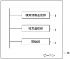
- FIG. 1 is a diagram illustrating a configuration example of a system according to the embodiment.
- FIG. 2 is a diagram illustrating an example of functional blocks of the beacon 10.
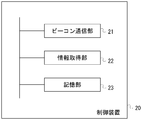
- FIG. 3 is a diagram illustrating an example of functional blocks of the control device 20.
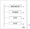
- FIG. 4 is a diagram illustrating an example of functional blocks of the terminal 30.
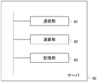
- FIG. 5 is a diagram illustrating an example of functional blocks of the server 40.
- FIG. 6 is a diagram illustrating an example of functional blocks of the terminal 50.
- FIG. 7 is a diagram illustrating a hardware configuration example of the information processing apparatus.
- FIG. 8 is a diagram illustrating an example of an operation sequence when changing the setting of the beacon in the beacon mesh from the control device.
- FIG. 9 is a diagram illustrating an example of an operation sequence in time synchronization in a beacon in a beacon mesh.
- FIG. 1 is a diagram illustrating a configuration example of a system according to the embodiment.
- the radio beacon transmission device in addition to the radio beacon transmitted and received for positioning or the like, the radio beacon transmission device is referred to as a beacon.
- the system according to the present embodiment includes a beacon 10 (in FIG. 1, beacon 10A to beacon 10E), a control device 20, a terminal 30, a server 40, and a terminal 50.
- the terminal 30 exists at a position where a signal from any one of the beacons 10 can be received.
- the terminal 30 is carried by a user or attached to a predetermined object.
- the control device 20, the server 40, and the terminal 50 are connected via a network 60 such as the Internet.
- the terminal 30 may be connected to the network 60.
- Beacon 10A to beacon 10E form a multi-hop wireless network.
- the beacon 10 transmits a wireless sign including identification information and transmission date / time.
- the beacon 10 according to the present embodiment has a function of communicating with other beacons 10 installed within the reach of radio waves, and forms a multi-hop wireless network as a whole.
- each of the plurality of beacons is arranged within the radio wave reach of at least one other beacon.
- the beacon 10 receives the identification information of the terminal 30 from the terminal 30.
- the beacon 10 transmits the identification information of the beacon 10 itself, the reception intensity of the signal from the terminal 30, information indicating the state of the beacon 10 and the like to the other beacons 10 together with the identification information from the terminal 30.
- the information indicating the state or the like of the beacon 10 may include a division method received from another beacon 10.
- a plurality of beacons that can communicate with each other are collectively referred to as a beacon mesh.
- the beacon 10 has, for example, a microcontroller and an antenna, and realizes various functions by cooperation of them.
- the beacon 10 can include various sensors as internal sensors.
- the various sensors are, for example, a camera, a microphone, a thermometer, a hygrometer, an optical sensor, an infrared sensor, an electric meter, a gas meter, a water meter, a measuring instrument, and the like. Images, images, sounds, values, etc. are detected by various sensors.
- Various sensors may be connected to the beacon 10 as external sensors.
- the beacon 10 can measure the remaining amount of the battery built in itself.
- the external sensor may have a wireless communication function using Bluetooth or the like. At this time, the external sensor can transmit a detection result or the like on a Bluetooth packet.
- the control device 20 is a device that centrally controls the operations of the plurality of beacons 10. For example, the control device 20 transmits specific information including identification information for specifying any of the plurality of beacons 10 and predetermined information to the surrounding beacons 10. On the other hand, when the beacon 10 relays the received specific information to the surrounding beacons 10 and receives specific information including identification information indicating itself, the beacon 10 performs a predetermined process based on the specific information.
- the specific information may include information for controlling the operation of the beacon 10, for example.
- the control device 20 operates as a gateway that connects the beacon mesh and the network 60.
- the terminal 30 receives a wireless sign from the beacon 10.
- the terminal 30 transmits identification information for identifying the terminal 30 itself to the beacon 10. 1 shows one terminal 30, the number of terminals 30 is not limited to one.
- the terminal 30 may have a function as the beacon 10.
- the terminal 30 may function as one beacon 10 in the beacon mesh.
- the terminal 30 may include an internal sensor or be connected to an external sensor.
- the terminal 30 may be carried by the user or attached to a movable object.
- the server 40 transmits a set of data such as identification information and transmission date / time of the beacon 10 included in the radio beacon from the terminal 30, reception date / time of the radio beacon at the terminal 30, and identification information of the terminal 30 via the beacon mesh. get.
- the server 40 can acquire information indicating the state of the beacon 10 and the like. Further, the server 40 outputs the acquired information to the terminal 50 or the like via the network 60.
- the server 40 may output information or the like according to the terminal 30.
- the terminal 50 is connected to the network 60 and receives information on the terminal 30 from the server 40. 1 shows one terminal 50, the number of terminals 50 is not limited to one.
- FIG. 2 is a diagram illustrating an example of functional blocks of the beacon 10 according to the embodiment.
- a plurality of beacons 10 are installed in a station premises such as a subway, an underground mall, a building, a tunnel, or the like at intervals equal to or shorter than a predetermined radio wave reachable distance. For example, it shall be installed at intervals of about 10 m depending on the installation location.
- the beacon 10 includes a sign information transmission unit 11, a mutual communication unit 12, and a storage unit 13.
- the beacon information transmission unit 11 transmits a radio beacon including identification information for identifying the beacon 10 based on the information held in the storage unit 13 and notifies the reception side device of proximity.
- the wireless sign may include date and time information indicating a transmission time. Specifically, a technique such as BLE (Bluetooth Low Energy) can be used, and wireless sign broadcast communication may be performed.
- BLE Bluetooth Low Energy
- the mutual communication unit 12 transmits and receives information to and from other beacons 10, terminals 30, and the control device 20. For example, mutual communication may be performed based on a profile such as GATT in BLE.
- the mutual communication unit 12 may perform connection-type communication.
- the mutual communication unit 12 receives specific information including identification information of another beacon 10
- the mutual communication unit 12 relays the specific information to surrounding beacons 10.
- specific information including identification information indicating itself is received, the specific information is stored in the storage unit 13 and a predetermined process is performed based on the specific information.
- the mutual communication unit 12 receives a signal including the terminal ID of the terminal 30 from the terminal 30.
- the mutual communication unit 12 measures the reception strength of the received signal.
- the mutual communication unit 12 stores the information included in the received signal in association with the reception intensity of the signal in the storage unit 13.
- the mutual communication unit 12 may respond to the control device 20 via the beacon mesh network with the information held in the storage unit 13 in response to a request from the control device 20.
- Information stored in the storage unit 13 may include information acquired by an internal sensor or an external sensor of the beacon 10.
- unique identification information may be assigned in advance to information such as specific information transmitted and received between the beacons 10.
- the mutual communication unit 12 stores the identification information of the transferred information once in the storage unit 13, and when the information is transferred, the identification information of the information transferred to the storage unit 13 in the past. If it is information transferred in the past, it is not necessary to transfer the information. Thereby, it can be avoided that the same information continues to be transferred in the beacon mesh.
- the storage unit 13 is a nonvolatile memory, and is realized by, for example, an EEPROM (ElectricallyrErasable Programmable Read-Only-Memory) such as a flash memory included in a microprocessor.
- the storage unit 13 stores predetermined identification information of the beacon 10, a set value of the radio wave intensity when the sign information transmission unit 11 transmits a wireless sign, and the like.
- the storage unit 13 stores information included in the received signal, reception intensity of the signal, and the like.
- FIG. 3 is a diagram illustrating an example of functional blocks of the control device 20 according to the embodiment.
- the control device 20 is, for example, a general computer, and includes a beacon communication unit 21, an information acquisition unit 22, and a storage unit 23.
- the beacon communication unit 21 performs bidirectional communication with the beacon 10. That is, the specific information mentioned above is transmitted, or life / death information or information held by the beacon 10 is received from the beacon 10.
- the control device 20 may be connected to one beacon 10 by wire or the like so as to be communicable.
- the information acquisition unit 22 acquires predetermined information from a device (not shown) via the network 60 such as the Internet or a dedicated line.
- the information acquisition unit 22 causes the beacon communication unit 21 to transmit specific information and change the setting of the beacon 10 based on an input from a user who operates the control device 20 or the like.
- the information acquisition unit 22 may acquire information from each beacon 10.
- identification information corresponding to all the beacons 10 may be included in the specific information, and the beacon 10 may broadcast the same specific information only once.
- the beacon 10 increments the number of hops every time the setting change information is transferred so that the specific information includes the number of hops indicating the number of times that the beacon mesh is transferred on the beacon mesh network. The specific information may be deleted from the beacon mesh.
- the storage unit 23 is realized by, for example, a hard disk drive (HDD), a solid state drive (SSD), a flash memory, or the like.
- storage part 23 memorize
- FIG. 4 is a diagram illustrating an example of functional blocks of the terminal 30 according to the embodiment.
- the terminal 30 is a computer such as a smartphone or a slate PC, for example, and includes a sign information transmission unit 31, a mutual communication unit 32, a storage unit 33, and a display unit 34.
- the sign information transmission unit 31 and the mutual communication unit 32 are realized by, for example, application software (also called a program) installed in the terminal 30 using the communication function of the terminal 30.
- the beacon information transmission unit 31 transmits a radio beacon including identification information for identifying the terminal 30 as the beacon 10 based on the information held in the storage unit 33, and notifies the reception side device of proximity. I do.
- the wireless sign may include date and time information indicating a transmission time. Specifically, a technique such as BLE (Bluetooth Low Energy) can be used, and wireless sign broadcast communication may be performed.
- the radio beacon (information) including the identification information of the terminal 30 transmitted by the terminal 30 can be received by a plurality of beacons.
- the mutual communication unit 32 transmits and receives information to and from other beacons 10, the terminals 30, and the control device 20. For example, mutual communication may be performed based on a profile such as GATT in BLE.
- the mutual communication unit 32 may perform connection-type communication.
- the mutual communication unit 32 receives specific information including identification information of another beacon 10
- the mutual communication unit 32 relays the specific information to surrounding beacons 10.
- specific information including identification information indicating itself is received, the specific information is stored in the storage unit 33 and predetermined processing is performed based on the specific information.
- the mutual communication 32 may respond to the control device 20 via the beacon mesh network with information held in the storage unit 33 in response to a request from the control device 20.
- the mutual communication unit 32 receives the radio beacon transmitted by the beacon 10 and stores it in the storage unit 33.
- the storage unit 33 is a volatile memory or a nonvolatile memory. For example, it is realized by a RAM (Random Access Memory), a ROM (Read Only Memory), an EEPROM such as a flash memory, or the like.
- the mutual communication unit 32 transmits the wireless label stored in the storage unit 33, the reception date and time of the wireless label, and the identification information for specifying the terminal 30 to the server 40 via the beacon mesh.
- the identification information for specifying the terminal 30 may use an ID provided by an OS (Operating System) such as a smartphone, or the server 40 may provide unique identification information for the application software of the terminal 30. May be issued.
- OS Operating System
- the storage unit 33 is realized by, for example, a hard disk drive (HDD), a solid state drive (SSD), a flash memory, or the like.
- the storage unit 33 stores identification information for identifying the terminal 30 from the terminal 30.
- storage part 33 memorize
- the display unit 34 displays the position information and other information stored in the storage unit 33 on a monitor provided in the terminal 30.
- FIG. 5 is a diagram illustrating an example of functional blocks of the information providing server 40 according to the embodiment.
- the server 40 is, for example, a stationary computer, and includes a communication unit 41, a calculation unit 42, and a storage unit 43.
- the control device 20 and the server 40 may be integrated to operate as one control device.
- the communication unit 41 transmits / receives information to / from the control device 20 and the terminal 50 via the network 60 such as the Internet. As described above, the communication unit 41 receives information including the identification information of the terminal 30 from the terminal 30 via the beacon mesh and the control device 20 and stores the information in the storage unit 43.
- the calculation unit 42 performs a predetermined calculation based on information from the beacon 10 or the terminal 30. For example, the calculation unit 42 calculates the position where the terminal 10 is present.
- the storage unit 43 includes, for example, an HDD, an SSD, a flash memory, and the like, and receives information from the terminal 30 via the beacon mesh and the control device 20, and information indicating the position of the terminal 30 calculated based on the information. In addition, information related to the vicinity of the position where the beacon 10 is installed may be stored in advance.
- storage part 43 matches and stores the identification information (beacon ID) of each beacon 10 of a beacon mesh, and the positional information which shows the presence position of each beacon.
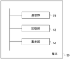
- FIG. 6 is a diagram illustrating an example of functional blocks of the terminal 50 according to the embodiment.
- the terminal 50 is a computer, for example, and includes a communication unit 51, a storage unit 52, and a display unit 53.
- the communication unit 51 transmits and receives information to and from the server 40 via a network 60 such as the Internet. As described above, for example, the communication unit 51 receives information including the position information of the terminal 30 from the server 40 and stores the information in the storage unit 52.
- the storage unit 52 includes, for example, an HDD, an SSD, a flash memory, or the like, and stores information received from the server 40.
- the storage unit 52 stores the position information of the terminal 30 received from the server 40.
- the storage unit 52 may store a map including an area (such as an underground mall) where the beacon 10 of the beacon mesh is installed.
- the display unit 53 displays the position information of the terminal 30 and other information stored in the storage unit 52 on a monitor provided in the terminal 50.
- the control device 20, the terminal 30, and the terminal 50 include a dedicated or general-purpose computer such as a smartphone, a mobile phone, a tablet terminal, a car navigation device, a PDA (Personal Digital Assistant), and a PC (Personal Computer), or a computer. This can be realized by using the electronic equipment.
- the server 40 can be realized using a dedicated or general-purpose computer such as a PC or a work station (WS), or an electronic device equipped with the computer.
- FIG. 7 is a diagram illustrating a hardware configuration example of the information processing apparatus.
- the information processing apparatus 90 shown in FIG. 7 has a general computer configuration.
- the control device 20, the terminal 30, the server 40, and the terminal 50 are realized by an information processing device 90 as shown in FIG.
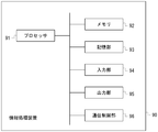
- the information processing apparatus 90 includes a processor 91, a memory 92, a storage unit 93, an input unit 94, an output unit 95, and a communication control unit 96. These are connected to each other by a bus.
- the memory 92 and the storage unit 93 are computer-readable recording media.
- the hardware configuration of the information processing apparatus is not limited to the example illustrated in FIG. 7, and components may be omitted, replaced, or added as appropriate.
- a processor 91 loads a program stored in a recording medium into a work area of the memory 92 and executes the program, and each component is controlled through execution of the program, thereby meeting a predetermined purpose. Function can be realized.
- the processor 91 is, for example, a CPU (Central Processing Unit) or a DSP (Digital Signal Processor).
- CPU Central Processing Unit
- DSP Digital Signal Processor
- the memory 92 includes, for example, a RAM (Random Access Memory) and a ROM (Read Only Memory).
- the memory 92 is also called a main storage device.
- the storage unit 93 is, for example, an EPROM (Erasable Programmable ROM), a hard disk drive (HDD, Hard Disk Drive), or a solid state drive (SSD, Solid State Drive).
- the storage unit 93 can include a removable medium, that is, a portable recording medium.
- the removable medium is, for example, a USB (Universal Serial Bus) memory or a disc recording medium such as a CD (Compact Disc) or a DVD (Digital Versatile Disc).
- the storage unit 93 is also called a secondary storage device.
- the storage unit 93 stores various programs, various data, and various tables in a recording medium in a readable and writable manner.
- the storage unit 93 stores an operating system (Operating System: OS), various programs, various tables, and the like.
- Information stored in the storage unit 93 may be stored in the memory 92.
- information stored in the memory 92 may be stored in the storage unit 93.
- the operating system is software that mediates between software and hardware, manages memory space, manages files, manages processes and tasks, and so on.
- the operating system includes a communication interface.
- the communication interface is a program for exchanging data with other external devices connected via the communication control unit 96. Examples of the external device include other information processing devices and external storage devices.
- the input unit 94 includes a keyboard, a pointing device, a wireless remote controller, a touch panel, and the like.
- the input unit 94 may include a video / image input device such as a camera, and an audio input device such as a microphone.
- the output unit 95 includes a display device such as a CRT (Cathode Ray Tube) display, an LCD (Liquid Crystal Display), a PDP (Plasma Display Panel), an EL (Electroluminescence) panel, and an output device such as a printer.
- the output unit 95 can include an audio output device such as a speaker.
- the communication control unit 96 is connected to another device and controls communication between the information processing device 90 and the other device.
- the communication control unit 96 is a wireless communication circuit for wireless communication such as a LAN (Local Area Network) interface board, Bluetooth (registered trademark), or a communication circuit for telephone communication.
- the LAN interface board and the wireless communication circuit are connected to a network such as the Internet.
- the computer that realizes the control device 20, the terminal 30, the server 40, and the terminal 50 implements each function by the processor loading and executing the program stored in the secondary storage device to the main storage device.
- the storage unit of each device is provided in a storage area of the main storage device or the secondary storage device.
- FIG. 8 is a diagram illustrating an example of an operation sequence when changing the setting of the beacon in the beacon mesh from the control device.
- the control device 20 changes the setting of the beacon 10.
- Each beacon 10 of the beacon mesh is installed in a predetermined space such as an underground mall or a tunnel. All beacons 10 are installed at positions where they can communicate with any other beacon 10. Further, at least one beacon 10 is installed at a position where it can communicate with the control device 20. It is assumed that the terminal 30 is present at a position where a radio beacon from at least one beacon 10 can be received.
- the control device 20 transmits a signal including an instruction (command, command) for changing the setting of the beacon 10D toward the beacon 10 of the beacon mesh including the beacon 10D.
- the signal is, for example, an advertisement signal (notification signal).
- the signal transmitted from the control device 20 may be a predetermined data signal of about 10 bytes used in mesh communication by Bluetooth.
- the signal used in mesh communication may be smaller than the advertise signal.
- the signal includes identification information for identifying the beacon 10D.
- a signal from the control device 20 may be received by a plurality of beacons 10. Here, it is assumed that the signal from the control device 20 is received by the beacon 10E.
- the control device 20 may transmit the signal as a beacon radio indicator.
- the instruction to change the setting may include raising / lowering the output, starting / stopping the output, detecting the signal reception intensity, adjusting the clock, detecting the remaining battery level, detecting various situations, and the like.
- Control device 20 may transmit a signal including an instruction to change the setting of beacon 10 other than beacon 10D.
- the control device 20 may transmit a signal including a setting change instruction based on a predetermined schedule.
- the beacon 10E that has received the signal from the control device 20 confirms the content of the signal.
- the beacon 10E confirms whether or not the information included in the received signal includes its own identification information and an instruction to change its setting. Here, it is assumed that the signal does not include identification information of the beacon 10E.
- the beacon 10E stores information included in the received signal in the storage unit 13.
- beacon 10E transmits a signal from control device 20 to surrounding beacons 10 and the like. Moreover, when the signal from the control apparatus 20 is the same signal as the signal transmitted previously, the beacon 10E does not transmit the signal. Here, it is assumed that the signal is received by the beacon 10D.
- the beacon 10D that has received the signal from the beacon 10E confirms the content of the signal.
- the beacon 10D confirms whether or not the information included in the received signal includes its own identification information and an instruction to change its setting.
- the signal includes identification information of the beacon 10D.
- the beacon 10D stores information included in the received signal in the storage unit 13.
- the beacon 10D when the beacon 10D recognizes that its own identification information is included in the received signal, the beacon 10D confirms the setting change instruction included in the received signal.
- the beacon 10D changes the setting of the beacon 10D in accordance with the setting change instruction.
- the setting change instruction is, for example, raising or lowering the output. At this time, the beacon 10D increases or decreases the transmission output setting value (transmission power) by one step.
- the setting change instruction may include output start / stop, clock adjustment, signal reception intensity detection, battery remaining amount detection, detection of various situations, and the like.
- the setting change instruction is recognized in the beacon 10 by, for example, a bit value at a predetermined position in the signal, which is determined in advance between the control device 20 and each beacon 10.
- the beacon 10D transmits a signal including information on the result of the setting change to the control device 20.
- the setting change result is, for example, an output set value after the setting change, reception intensity, remaining battery level, various meter values, detection value, and the like.
- the setting change result may be a value based on the output setting value after changing the setting, the received intensity, the remaining battery level, the values of various meters, the detection value, etc. in order to reduce the data amount.
- the signal is, for example, an advertisement signal (notification signal).
- the signal may be, for example, a small data signal of about 10 bytes used in Bluetooth mesh communication.
- the signal may include identification information for identifying the control device 20 as information indicating that the control device 20 is addressed.
- the signal may include identification information for identifying the control device 20 as information indicating the beacon 10D that is the transmission source of the signal.
- the result of the setting change is expressed by, for example, a bit value at a predetermined position in the signal, which is determined in advance between the control device 20 and each beacon 10.
- the signal is received by the beacon 10E.
- the beacon 10E that has received the signal from the beacon 10D confirms the content of the signal.
- the beacon 10E confirms whether or not the information included in the received signal includes its own identification information and an instruction to change its setting. Here, it is assumed that the signal does not include identification information of the beacon 10E.
- the beacon 10E stores information included in the received signal in the storage unit 13.
- beacon 10E transmits a signal from beacon 10D to surrounding beacons 10 and the like. Moreover, beacon 10E does not transmit the said signal, when the said signal from beacon 10D is the same signal as the signal transmitted previously. Here, it is assumed that the signal is received by the control device 20.
- the control device 20 that has received the signal from the beacon 10E confirms the content of the signal.
- the control device 20 confirms whether the information included in the received signal includes its own identification information or the like. Here, it is assumed that the signal includes identification information of the control device 20.
- the control device 20 stores information included in the received signal in the storage unit 23.
- the control device 20 confirms information included in the signal received from the beacon 10E. Based on the information, the control device 20 can recognize the setting change result for the setting change instruction performed on the beacon 10D.
- the control device 20 can instruct setting change for the beacon 10D using a data signal used in mesh communication by Bluetooth. Moreover, the control apparatus 20 can receive the setting change result from beacon 10D, and can confirm the content of a setting change. For example, if a transmission arrival confirmation / retransmission request such as a 3-way handshake is made as in TCP, it is possible to confirm whether the packet has been correctly communicated and the setting has been changed. This leads to an increase in the number of communication efficiency.
- the control device 20 can recognize the setting change result while suppressing an increase in the amount of the signal.
- FIG. 9 is a diagram illustrating an example of an operation sequence in time synchronization in a beacon in a beacon mesh.
- the beacon 10 in the beacon mesh is battery-powered, it is required to reduce the power consumption per hour used in the beacon 10 by shortening the time during which the beacon 10 operates. By reducing the power consumption per hour, the frequency of battery replacement can be lowered.
- the time zone in which the beacon 10 operates is matched in the beacon mesh, it becomes difficult to transmit and receive signals. Therefore, it is required to perform time synchronization within the beacon mesh.
- performing time synchronization of the beacon 10 in the beacon mesh by a signal from the control device 20 will be described.
- the control device 20 directs a signal (time synchronization command, time synchronization signal) including a time synchronization instruction (command, command) to all the beacons 10 in the beacon mesh to the beacon 10 of the beacon mesh.
- the signal is, for example, an advertisement signal (notification signal).
- the signal transmitted from the control device 20 may be a predetermined data signal of about 10 bytes used in mesh communication by Bluetooth.
- the signal used in mesh communication may be smaller than the advertise signal.
- the signal includes information indicating a time synchronization instruction.
- a signal from the control device 20 may be received by a plurality of beacons 10. Here, it is assumed that the signal from the control device 20 is received by the beacon 10E.
- the control device 20 may transmit the signal as a beacon radio indicator.
- the time synchronization instruction may include an instruction other than time synchronization.
- the control device 20 may transmit a signal including a time synchronization instruction based on a predetermined schedule.
- the signal may include identification information for identifying the current signal.
- the beacon 10E that has received the signal from the control device 20 confirms the content of the signal.
- the beacon 10E recognizes that it is a time synchronization signal from the information included in the received signal.
- the beacon 10E stores information included in the received signal in the storage unit 13.
- the beacon 10E transmits a signal from the control device 20 to the surrounding beacons 10 and the like. Moreover, when the signal from the control apparatus 20 is the same signal as the signal transmitted previously, the beacon 10E does not transmit the signal. Here, it is assumed that the signal is received by the beacon 10D.
- the beacon 10D that has received the signal from the beacon 10E confirms the content of the signal.
- beacon 10D recognizes that it is a time synchronous signal from the information contained in the received signal.
- the beacon 10D stores information included in the received signal in the storage unit 13.
- the beacon 10D transmits a signal from the beacon 10E to the surrounding beacons 10 and the like, like the beacon 10E. Moreover, beacon 10D does not transmit the said signal, when the signal from the control apparatus 20 is the same signal as the signal transmitted previously.
- the beacon 10 (beacon 10D, beacon 10E, etc.) that has received the time synchronization signal sets the time of the clock built in itself to a predetermined reference time (for example, time 0).
- a predetermined reference time for example, time 0
- a time lag occurs at the timing when each beacon 10 receives the time synchronization signal, but in the time scale handled here, in each beacon 10, It can be considered that the time synchronization signal is received almost simultaneously.
- a clock built in the beacon 10 counts time.
- the beacon 10 sleeps its own device for a predetermined time. During the time when the beacon 10 is sleeping, the beacon 10 stops signal transmission / reception. Thereby, the power consumption in the beacon 10 can be suppressed.
- the beacon 10 performs signal transmission / reception for a predetermined time when a predetermined time elapses after sleeping in SQ2004. Thereby, transmission and reception of signals can be performed in the same time zone as other beacons 10.
- each beacon 10 Thereafter, in each beacon 10, the processes of SQ2004 and SQ2005 are repeated. This process is stopped when the next time synchronization signal is received.
- the length of time for which the beacon 10 sleeps and the length of time for transmission and reception may be determined in advance or may be specified in the time synchronization signal.
- the time synchronization signal is periodically transmitted from the control device 20, whereby the time lag due to the individual difference in the timepiece incorporated in the beacon 10 can be eliminated.
- time synchronization can be performed even when a new beacon 10 is added to the beacon mesh by periodically transmitting a time synchronization signal from the control device 20.
- the beacon 10 in the surrounding mesh beacon which recognized the addition of the new beacon 10 may transmit a signal including the elapsed time from the reference time to the new beacon 10 to perform time synchronization. Furthermore, there is a possibility that the time of the clock of the beacon 10 that has transmitted a signal including the elapsed time from the reference time to the new beacon 10 is incorrect. If an incorrect time is set in the clock of the beacon 10, signals from other beacons 10 and the control device 20 may not be received. Therefore, when the beacon 10 does not receive a signal (time synchronization signal or the like) from the control device 20 for a predetermined period, the beacon 10 determines that the time of the clock is incorrect and receives the signal from the control device 20. Until then, the reception state may be maintained without going to sleep. Thereby, even when the time of the clock of the beacon 10 is deviated, it can be adjusted to the correct time.
- the beacon 10 of the beacon mesh can transmit and receive Bluetooth packets.
- a sensor network can be constructed by collecting Bluetooth packets (detection signals) from external sensors by the control device 20 via mesh communication in a beacon mesh.
- the Bluetooth packet by the external sensor includes a detection result of some physical quantity by the external sensor.
- the detection result by the internal sensor incorporated in the beacon 10 of the beacon mesh may be placed on the Bluetooth packet and collected by the control device 20.
- detection results (sensor information and the like) by various sensors can be collected in the control device 20 in the same manner as the setting change result is transmitted from the beacon 10 ⁇ / b> D to the control device 20.
- Each beacon 10 may forward the received Bluetooth packet from the external sensor to the control device 20 as it is.
- the information transmitted from the various sensors and beacons 10 to the control device 20 may be a value based on the detection result in order to reduce the amount of data. By filtering the detection result, the data amount of the value based on the detection result can be reduced.
- the control device 20 may calculate the position of the external sensor by collecting the transmission power of the external sensor and the reception power of the signal from the external sensor in the beacon 10. Since the magnitude of the received power depends on the distance from the beacon 10, if the signals from the external sensor can be received by the plurality of beacons 10, the distance from the plurality of beacons 10 to the external sensor can be known. Can be calculated.
- the beacon 10 in the beacon mesh of this embodiment receives a signal including a setting change instruction from the control device 20.
- the beacon 10 changes the setting based on the setting change instruction.
- the beacon 10 transmits a signal including the setting change result to the control device 20.
- the beacon 10 can transmit the result of the setting change by using a packet of mesh communication in the beacon mesh.
- the control device 20 in the beacon mesh of the present embodiment receives the time synchronization signal toward the beacon 10 in the beacon mesh.
- Each beacon 10 that has received the time synchronization signal sets the time of the built-in clock as the reference time.
- Each beacon 10 sleeps for a predetermined period.
- Each beacon 10 transmits and receives signals for a predetermined period after a predetermined period of sleep. Thereby, the power consumption in the beacon 10 can be suppressed.
- the beacon 10 can receive a wireless signal including a detection result by an external sensor and transmit it to the control device 20.
- the control apparatus 20 can acquire the detection result by an external sensor via a beacon mesh.
- Computer-readable recording medium A program for causing a computer or other machine or device (hereinafter, a computer or the like) to realize any of the above functions can be recorded on a recording medium that can be read by the computer or the like.
- the function can be provided by causing a computer or the like to read and execute the program of the recording medium.
- a computer-readable recording medium is a recording medium that stores information such as data and programs by electrical, magnetic, optical, mechanical, or chemical action and can be read from a computer or the like.
- elements constituting a computer such as a CPU and a memory may be provided to cause the CPU to execute a program.
- recording media that can be removed from a computer or the like, there are, for example, a flexible disk, a magneto-optical disk, a CD-ROM, a CD-R / W, a DVD, a DAT, an 8 mm tape, and a memory card.
- a hard disk a ROM, etc. as a recording medium fixed to a computer or the like.
Landscapes
- Engineering & Computer Science (AREA)
- Computer Networks & Wireless Communication (AREA)
- Signal Processing (AREA)
- Mobile Radio Communication Systems (AREA)
- Radio Relay Systems (AREA)
Abstract
メッシュビーコンにおけるビーコンを制御する。所定の電波到達距離内において相互に通信可能であり、所定の信号を送受信する複数のビーコンであって、当該複数のビーコンのそれぞれは、少なくとも1つの他のビーコンの前記電波到達距離内に配置される複数のビーコンと、前記複数のビーコンのうちの少なくとも1つのビーコンと通信可能である制御装置とを含むシステムにおけるビーコンであって、前記制御装置から発信された設定変更指示を含む信号を受信する受信手段と、前記設定変更指示に基づいて、自装置の所定項目の設定値を変更する設定手段と、前記設定手段により変更された設定値に基づく情報を含む信号を前記制御装置に向けて送信する送信手段と、を備えるビーコンとする。
Description
本発明は、ビーコンに関する。
電磁波等を発射することにより、受信機に位置等の様々な情報を通知するビーコン(無線標識)が存在する。ビーコンには、モバイルコンピュータに向けて情報を発信するものもある。例えば、モバイルコンピュータ用のビーコンには、Bluetooth(登録商標)を利用したものもあり、複数の送信器から識別情報を受信することで、受信側のコンピュータは自身の位置を知ることができる。
また、受信機を備える自動車等の移動体に向けて情報を送信するビーコンには、無線通信監視装置がビーコンの送信レベル情報をビーコンに送信し、ビーコンの送信レベルを調整する情報通信システムが提案されている。
複数のビーコンによりビーコンメッシュを構成する技術がある。ビーコンメッシュを構成するビーコン(メッシュ型ビーコンともいう)は、電波の到達距離内に設置された他のビーコンと相互に通信を行う機能を有し、全体としてマルチホップ無線ネットワークを形成する。メッシュ型ビーコンは、他のビーコンに対して、自身の識別情報を含む無線標識を送信する。ビーコンメッシュは、ゲートウェイを介して、他のネットワークに接続され得る。ゲートウェイは、ビーコンメッシュ内のビーコンに対して、個別に、設定変更の命令を送信することができる。しかし、ゲートウェイでは、各ビーコンにおける設定変更の結果を認識することが困難であった。
本発明は、メッシュビーコンにおけるビーコンを制御する技術を提供することを課題とする。
上記課題を解決するために、以下の手段を採用する。
即ち、第1の態様は、
所定の電波到達距離内において相互に通信可能であり、所定の信号を送受信する複数のビーコンであって、当該複数のビーコンのそれぞれは、少なくとも1つの他のビーコンの前記電波到達距離内に配置される複数のビーコンと、前記複数のビーコンのうちの少なくとも1つのビーコンと通信可能である制御装置とを含むシステムにおけるビーコンであって、
前記制御装置から発信された設定変更指示を含む信号を受信する受信手段と、
前記設定変更指示に基づいて、自装置の所定項目の設定値を変更する設定手段と、
前記設定手段により変更された設定値に基づく情報を含む信号を前記制御装置に向けて送信する送信手段と、
を備えるビーコンとする。
開示の態様は、プログラムが情報処理装置によって実行されることによって実現されてもよい。即ち、開示の構成は、上記した態様における各手段が実行する処理を、情報処理装置に対して実行させるためのプログラム、或いは当該プログラムを記録したコンピュータ読み取り可能な記録媒体として特定することができる。また、開示の構成は、上記した各手段が実行する処理を情報処理装置が実行する方法をもって特定されてもよい。開示の構成は、上記した各手段が実行する処理を行う情報処理装置を含むシステムとして特定されてもよい。
本発明によれば、メッシュビーコンにおけるビーコンを制御することができる。
以下、図面を参照して本発明の実施形態について説明する。実施形態の構成は例示であり、発明の構成は、開示の実施形態の具体的構成に限定されない。発明の実施にあたって、実施形態に応じた具体的構成が適宜採用されてもよい。
〔実施形態〕
〈システム構成〉
図1は、実施形態に係るシステムの構成例を示す図である。なお、本実施形態では、測位等のために送受信される無線標識のほか当該無線標識の送信装置をビーコンと呼ぶ。本実施形態に係るシステムは、ビーコン10(図1では、ビーコン10Aからビーコン10E)、制御装置20、端末30、サーバ40、端末50を含む。端末30は、いずれかのビーコン10からの信号を受信できる位置に存在する。端末30は、例えば、利用者に携帯されていたり、所定の物に添付されていたりする。制御装置20、サーバ40、端末50は、インターネット等のネットワーク60を介して接続されている。端末30は、ネットワーク60に接続されていてもよい。ビーコン10Aからビーコン10Eは、マルチホップ無線ネットワークを形成している。
ビーコン10は、識別情報及び送信日時を含む無線標識を送信する。また、本実施形態に係るビーコン10は、電波の到達距離内に設置された他のビーコン10と相互に通信を行う機能を有し、全体としてマルチホップ無線ネットワークを形成する。また、複数のビーコンの各々は少なくとも1つの他のビーコンの電波到達距離内に配置されるものとする。ビーコン10は、端末30から、当該端末30の識別情報を受信する。ビーコン10は、端末30からの識別情報とともに、ビーコン10自身の識別情報、端末30からの信号の受信強度、ビーコン10の状態等を示す情報等を、他のビーコン10に向けて送信する。ビーコン10の状態等を示す情報には、他のビーコン10から受信した除法を含み得る。なお、相互に通信可能とした複数のビーコンを総称してビーコンメッシュとも呼ぶ。また、図1では5つのビーコン10を例示したが、ビーコン10の数は5つには限定されるものではない。ビーコン10は、例えば、マイクロコントローラとアンテナとを有し、これらが協働することにより各種の機能を実現する。ビーコン10は、内部センサとして、各種センサを含み得る。各種センサは、例えば、カメラ、マイク、温度計、湿度計、光センサ、赤外線センサ、電気メータ、ガスメータ、水道メータ、計測器等である。各種センサによって、映像、画像、音、値等が検出される。また、ビーコン10には、外部センサとして、各種センサが接続されてもよい。ビーコン10は、自身に内蔵される電池の残量を計測しうる。外部センサは、Bluetooth等による無線通信機能を有してもよい。このとき、外部センサは、Bluetoothのパケットに載せて検出結果等を送信しうる。
制御装置20は、複数のビーコン10の動作を一元的に制御する装置である。制御装置20は、例えば、複数のビーコン10のいずれかを特定する識別情報と所定の情報とを含む特定情報を、周辺のビーコン10に送信する。一方、ビーコン10は、受信した特定情報を周辺のビーコン10へ中継すると共に、自身を示す識別情報を含む特定情報を受信した場合、当該特定情報に基づいて、所定の処理を行う。特定情報は、例えば、ビーコン10の動作を制御する情報を含み得る。制御装置20は、ビーコンメッシュとネットワーク60とを接続するゲートウェイとして動作する。
端末30は、ビーコン10から無線標識を受信する。端末30は、ビーコン10に対して、端末30自身を識別する識別情報を送信する。また、図1には1つの端末30を示しているが、端末30の数は、1つに限定されるものではない。端末30は、ビーコン10としての機能を有してもよい。例えば、端末30は、ビーコンメッシュ内の1つのビーコン10として機能してもよい。端末30は、ビーコン10と同様に、内部センサを含んだり、外部センサに接続されたりしてもよい。端末30は、利用者に携帯されていたり、移動しうる物に添付されていたりする。
サーバ40は、例えば、端末30から無線標識に含まれるビーコン10の識別情報及び送信日時、端末30における無線標識の受信日時、並びに、端末30の識別情報といったデータのセットを、ビーコンメッシュを介して取得する。サーバ40は、ビーコン10の状態等を示す情報を取得しうる。また、サーバ40は、取得した情報を、ネットワーク60を介して端末50等に出力する。なお、サーバ40は、端末30に応じた情報等を出力するようにしてもよい。
端末50は、ネットワーク60に接続され、サーバ40から、端末30の情報等を受信する。また、図1には1つの端末50を示しているが、端末50の数は、1つに限定されるものではない。
〈ビーコンの機能構成〉
図2は、実施形態に係るビーコン10の機能ブロックの例を示す図である。なお、ビーコン10は、地下鉄等の駅構内や地下街、建築物、トンネル内等に、相互に通信可能な所定の電波到達距離以下の間隔で複数設置される。例えば、設置場所に応じて、10m程度といった間隔で設置するものとする。ビーコン10は、標識情報送信部11と、相互通信部12と、記憶部13とを備える。
図2は、実施形態に係るビーコン10の機能ブロックの例を示す図である。なお、ビーコン10は、地下鉄等の駅構内や地下街、建築物、トンネル内等に、相互に通信可能な所定の電波到達距離以下の間隔で複数設置される。例えば、設置場所に応じて、10m程度といった間隔で設置するものとする。ビーコン10は、標識情報送信部11と、相互通信部12と、記憶部13とを備える。
標識情報送信部11は、記憶部13に保持されている情報に基づいて、当該ビーコン10を識別するための識別情報を含む無線標識を送信し、受信側の装置に対して近接通知を行う。無線標識は、送信時刻を示す日時情報等を含んでもよい。具体的には、BLE(Bluetooth Low Energy)等の技術を利用することができ、無線標識のブロードキャスト通信を行うようにしてもよい。
相互通信部12は、他のビーコン10、端末30、制御装置20との間で双方向に情報の送受信を行う。例えば、BLEにおけるGATTのようなプロファイルに基づいて相互通信を行うようにしてもよい。相互通信部12は、コネクション型の通信を行ってもよい。また、相互通信部12は、他のビーコン10の識別情報を含む特定情報を受信した場合、当該特定情報を周辺のビーコン10へ中継する。一方、自身を示す識別情報を含む特定情報を受信した場合、当該特定情報を記憶部13に格納すると共に、当該特定情報に基づいて、所定の処理を行う。相互通信部12は、端末30から端末30の端末IDを含む信号を受信する。相互通信部12は、受信した信号の受信強度を測定する。相互通信部12は、受信した信号に含まれる情報と当該信号の受信強度を対応付けて、記憶部13に格納する。
また、相互通信部12は、制御装置20からの要求に応じて、記憶部13に保持されている情報を、ビーコンメッシュのネットワークを介して制御装置20に応答するようにしてもよい。記憶部13に保持されている情報には、ビーコン10の内部センサや外部センサで取得された情報が含まれ得る。また、ビーコン10間を送受信される特定情報等の情報には、あらかじめ、固有の識別情報が割り当てられてもよい。このとき、相互通信部12は、一度、転送した情報の識別情報を記憶部13に格納し、情報を転送する際に、当該情報の識別情報が記憶部13に過去に転送した情報の識別情報と一致するか否かを確認し、過去に転送した情報である場合には、当該情報を転送しなくてもよい。これにより、同じ情報がビーコンメッシュ内を転送され続けることを回避することができる。
記憶部13は、不揮発性メモリであり、例えばマイクロプロセッサが有するフラッシュメモリのようなEEPROM(Electrically Erasable Programmable Read-Only Memory)等によって実現される。また、記憶部13は、予め定められた当該ビーコン10の識別情報や、標識情報送信部11が無線標識を送信する際の電波強度の設定値等を記憶する。記憶部13は、受信した信号に含まれる情報や当該信号の受信強度などを格納する。
〈制御装置の機能構成〉
図3は、実施形態に係る制御装置20の機能ブロックの例を示す図である。制御装置20は、例えば一般的なコンピュータであり、ビーコン通信部21と、情報取得部22と、記憶部23とを備える。ビーコン通信部21は、ビーコン10と双方向の通信を行う。すなわち、上述した特定情報を送信したり、ビーコン10から死活情報やビーコン10が保持する情報を受信したりする。制御装置20は、1つのビーコン10と通信可能に有線等で接続されていてもよい。
図3は、実施形態に係る制御装置20の機能ブロックの例を示す図である。制御装置20は、例えば一般的なコンピュータであり、ビーコン通信部21と、情報取得部22と、記憶部23とを備える。ビーコン通信部21は、ビーコン10と双方向の通信を行う。すなわち、上述した特定情報を送信したり、ビーコン10から死活情報やビーコン10が保持する情報を受信したりする。制御装置20は、1つのビーコン10と通信可能に有線等で接続されていてもよい。
情報取得部22は、例えば、インターネットや専用回線等のネットワーク60を介して、図示していない装置から所定の情報を取得する。また、情報取得部22は、制御装置20を操作するユーザからの入力等に基づいて、ビーコン通信部21に特定情報を送信させ、ビーコン10の設定を変更させる。また、情報取得部22は、各々のビーコン10から情報を取得してもよい。また、特定情報にすべてのビーコン10に対応する識別情報を含むようにして、ビーコン10は同一の特定情報を1回のみブロードキャスト通信するようにしてもよい。また、特定情報がビーコンメッシュのネットワーク上を転送される回数を示すホップ数を含むようにして、ビーコン10は設定変更情報を転送するたびにホップ数をインクリメントし、所定の回数だけビーコン10間を転送された特定情報がビーコンメッシュ上から削除されるようにしてもよい。
記憶部23は、例えば、HDD(Hard-disk Drive)やSSD(Solid State Drive)、フラッシュメモリ等によって実現される。記憶部23は、各ビーコンの識別情報(ビーコンID)に対応付けて、複数のビーコン10の設置場所を示す位置情報、動作設定等を記憶する。
〈端末の機能構成〉
図4は、実施形態に係る端末30の機能ブロックの例を示す図である。端末30は、例えばスマートフォンやスレートPC等のコンピュータであり、標識情報送信部31と、相互通信部32と、記憶部33と、表示部34とを備える。なお、標識情報送信部31、相互通信部32は、例えば端末30にインストールされたアプリケーションソフトウェア(プログラムとも呼ぶ)が、端末30の通信機能を利用して実現する。
図4は、実施形態に係る端末30の機能ブロックの例を示す図である。端末30は、例えばスマートフォンやスレートPC等のコンピュータであり、標識情報送信部31と、相互通信部32と、記憶部33と、表示部34とを備える。なお、標識情報送信部31、相互通信部32は、例えば端末30にインストールされたアプリケーションソフトウェア(プログラムとも呼ぶ)が、端末30の通信機能を利用して実現する。
標識情報送信部31は、記憶部33に保持されている情報に基づいて、ビーコン10としての端末30を識別するための識別情報を含む無線標識を送信し、受信側の装置に対して近接通知を行う。無線標識は、送信時刻を示す日時情報等を含んでもよい。具体的には、BLE(Bluetooth Low Energy)等の技術を利用することができ、無線標識のブロードキャスト通信を行うようにしてもよい。端末30が送信する端末30の識別情報を含む無線標識(情報)は、複数のビーコンによって受信され得る。
相互通信部32は、他のビーコン10、端末30、制御装置20との間で双方向に情報の送受信を行う。例えば、BLEにおけるGATTのようなプロファイルに基づいて相互通信を行うようにしてもよい。相互通信部32は、コネクション型の通信を行ってもよい。また、相互通信部32は、他のビーコン10の識別情報を含む特定情報を受信した場合、当該特定情報を周辺のビーコン10へ中継する。一方、自身を示す識別情報を含む特定情報を受信した場合、当該特定情報を記憶部33に格納すると共に、当該特定情報に基づいて、所定の処理を行う。また、相互通信32は、制御装置20からの要求に応じて、記憶部33に保持されている情報を、ビーコンメッシュのネットワークを介して制御装置20に応答するようにしてもよい。
相互通信部32は、ビーコン10が送信する無線標識を受信し、記憶部33に記憶させる。記憶部33は、揮発性メモリ又は不揮発性メモリである。例えば、RAM(Random Access Memory)やROM(Read Only Memory)、フラッシュメモリのようなEEPROM等によって実現される。また、相互通信部32は、記憶部33に記憶されている無線標識、当該無線標識の受信日時及び端末30を特定するための識別情報を、ビーコンメッシュを介してサーバ40に送信する。なお、端末30を特定するための識別情報は、スマートフォン等のOS(Operating System)が提供するIDを利用するようにしてもよいし、サーバ40が端末30のアプリケーションソフトウェアに対して独自の識別情報を発行するようにしてもよい。
記憶部33は、例えば、HDD(Hard-disk Drive)やSSD(Solid State Drive)、フラッシュメモリ等によって実現される。記憶部33は、端末30からの端末30を識別するための識別情報を格納する。記憶部33は、各ビーコンの識別情報(ビーコンID)に対応付けて、複数のビーコン10の設置場所を示す位置情報等を記憶する。
表示部34は、記憶部33に記憶された位置情報やその他の情報を端末30が備えるモニタに表示させる。
〈サーバの機能構成〉
図5は、実施形態に係る情報提供サーバ40の機能ブロックの例を示す図である。サーバ40は、例えば、据え置き型のコンピュータであり、通信部41と、演算部42と、記憶部43とを備える。制御装置20とサーバ40とは一体化して、1つの制御装置として動作してもよい。
図5は、実施形態に係る情報提供サーバ40の機能ブロックの例を示す図である。サーバ40は、例えば、据え置き型のコンピュータであり、通信部41と、演算部42と、記憶部43とを備える。制御装置20とサーバ40とは一体化して、1つの制御装置として動作してもよい。
通信部41は、インターネット等のネットワーク60を介して制御装置20、端末50との間で情報を送受信する。上述のように、通信部41は、ビーコンメッシュ、制御装置20を介して、端末30からの端末30の識別情報を含む情報を受信し、記憶部43に記憶させる。
演算部42は、ビーコン10や端末30からの情報に基づいて、所定の演算を行う。演算部42は、例えば、端末10が存在する位置を算出する。
記憶部43は、例えばHDDやSSD、フラッシュメモリ等によって構成され、端末30から、ビーコンメッシュ、制御装置20を介して、受信した情報や、当該情報に基づいて算出した端末30の位置を示す情報を記憶するほか、ビーコン10が設置された位置の周辺に関する情報を予め記憶してもよい。記憶部43は、ビーコンメッシュの各ビーコン10の識別情報(ビーコンID)と、各ビーコンの存在位置を示す位置情報とを対応付けて格納する。
〈端末の機能構成〉
図6は、実施形態に係る端末50の機能ブロックの例を示す図である。端末50は、例えば、コンピュータであり、通信部51と、記憶部52と、表示部53とを備える。
図6は、実施形態に係る端末50の機能ブロックの例を示す図である。端末50は、例えば、コンピュータであり、通信部51と、記憶部52と、表示部53とを備える。
通信部51は、インターネット等のネットワーク60を介してサーバ40との間で情報を送受信する。上述のように、通信部51は、例えば、サーバ40から、端末30の位置情報を含む情報を受信し、記憶部52に記憶させる。
記憶部52は、例えばHDDやSSD、フラッシュメモリ等によって構成され、サーバ40から受信した情報等を記憶する。記憶部52は、サーバ40から受信した、端末30の位置情報等を格納する。記憶部52は、ビーコンメッシュのビーコン10が設置されるエリア(地下街等)を含む地図が格納してもよい。
表示部53は、記憶部52に記憶された端末30の位置情報やその他の情報を端末50が備えるモニタに表示させる。
〈装置構成〉
制御装置20、端末30、端末50は、スマートフォン、携帯電話、タブレット型端末、カーナビゲーション装置、PDA(Personal Digital Assistant)、PC(Personal Computer)のような専用または汎用のコンピュータ、あるいは、コンピュータを搭載した電子機器を使用して実現可能である。サーバ40は、PC、ワークステーション(WS、Work Station)のような専用または汎用のコンピュータ、あるいは、コンピュータを搭載した電子機器を使用して実現可能である。
制御装置20、端末30、端末50は、スマートフォン、携帯電話、タブレット型端末、カーナビゲーション装置、PDA(Personal Digital Assistant)、PC(Personal Computer)のような専用または汎用のコンピュータ、あるいは、コンピュータを搭載した電子機器を使用して実現可能である。サーバ40は、PC、ワークステーション(WS、Work Station)のような専用または汎用のコンピュータ、あるいは、コンピュータを搭載した電子機器を使用して実現可能である。
図7は、情報処理装置のハードウェア構成例を示す図である。図7に示す情報処理装置90は、一般的なコンピュータの構成を有している。制御装置20、端末30、サーバ40、端末50は、図7に示すような情報処理装置90によって実現される。情報処理装置90は、プロセッサ91、メモリ92、記憶部93、入力部94、出力部95、通信制御部96を有する。これらは、互いにバスによって接続される。メモリ92及び記憶部93は、コンピュータ読み取り可能な記録媒体である。情報処理装置のハードウェア構成は、図7に示される例に限らず、適宜構成要素の省略、置換、追加が行われてもよい。
情報処理装置90は、プロセッサ91が記録媒体に記憶されたプログラムをメモリ92の作業領域にロードして実行し、プログラムの実行を通じて各構成部等が制御されることによって、所定の目的に合致した機能を実現することができる。
プロセッサ91は、例えば、CPU(Central Processing Unit)やDSP(Digital Signal Processor)である。
メモリ92は、例えば、RAM(Random Access Memory)やROM(Read Only Memory)を含む。メモリ92は、主記憶装置とも呼ばれる。
記憶部93は、例えば、EPROM(Erasable Programmable ROM)、ハードディスクドライブ(HDD、Hard Disk Drive)、ソリッドステートドライブ(SSD、Solid State Drive)である。また、記憶部93は、リムーバブルメディア、即ち可搬記録媒体を含むことができる。リムーバブルメディアは、例えば、USB(Universal Serial Bus)メモリ、あるいは、CD(Compact Disc)やDVD(Digital Versatile Disc)のようなディスク記録媒体である。記憶部93は、二次記憶装置とも呼ばれる。
記憶部93は、各種のプログラム、各種のデータ及び各種のテーブルを読み書き自在に記録媒体に格納する。記憶部93には、オペレーティングシステム(Operating System :OS)、各種プログラム、各種テーブル等が格納される。記憶部93に格納される情報は、メモリ92に格納されてもよい。また、メモリ92に格納される情報は、記憶部93に格納されてもよい。
オペレーティングシステムは、ソフトウェアとハードウェアとの仲介、メモリ空間の管理、ファイル管理、プロセスやタスクの管理等を行うソフトウェアである。オペレーティングシステムは、通信インタフェースを含む。通信インタフェースは、通信制御部96を介して接続される他の外部装置等とデータのやり取りを行うプログラムである。外部装置等には、例えば、他の情報処理装置、外部記憶装置等が含まれる。
入力部94は、キーボード、ポインティングデバイス、ワイヤレスリモコン、タッチパネル等を含む。また、入力部94は、カメラのような映像や画像の入力装置や、マイクロフォンのような音声の入力装置を含むことができる。
出力部95は、CRT(Cathode Ray Tube)ディスプレイ、LCD(Liquid Crystal Display)、PDP(Plasma Display Panel)、EL(Electroluminescence)パネル等の表示装置、プリンタ等の出力装置を含む。また、出力部95は、スピーカのような音声の出力装置を含むことができる。
通信制御部96は、他の装置と接続し、情報処理装置90と他の装置との間の通信を制御する。通信制御部96は、例えば、LAN(Local Area Network)インタフェースボード、Bluetooth(登録商標)などの無線通信のための無線通信回路、電話通信のための通信回路である。LANインタフェースボードや無線通信回路は、インターネット等のネットワークに接続される。
制御装置20、端末30、サーバ40、端末50を実現するコンピュータは、プロセッサが二次記憶装置に記憶されているプログラムを主記憶装置にロードして実行することによって、各機能を実現する。また、各装置の記憶部は、主記憶装置または二次記憶装置の記憶領域に設けられる。
〈動作例〉
《設定変更》
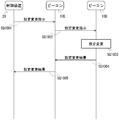
図8は、制御装置から、ビーコンメッシュ内のビーコンの設定変更を行う際の動作シーケンスの例を示す図である。ここでは、図1に示すようなシステムにおいて、制御装置20が、ビーコン10の設定変更を行う。ビーコンメッシュの各ビーコン10は、地下街、トンネルなどの所定の空間に設置されている。すべてのビーコン10は、いずれかの他のビーコン10と通信できる位置に設置される。また、少なくとも1つのビーコン10は、制御装置20と通信できる位置に設置される。端末30は、少なくとも1つのビーコン10からの無線標識を受信できる位置に存在しているとする。
《設定変更》
図8は、制御装置から、ビーコンメッシュ内のビーコンの設定変更を行う際の動作シーケンスの例を示す図である。ここでは、図1に示すようなシステムにおいて、制御装置20が、ビーコン10の設定変更を行う。ビーコンメッシュの各ビーコン10は、地下街、トンネルなどの所定の空間に設置されている。すべてのビーコン10は、いずれかの他のビーコン10と通信できる位置に設置される。また、少なくとも1つのビーコン10は、制御装置20と通信できる位置に設置される。端末30は、少なくとも1つのビーコン10からの無線標識を受信できる位置に存在しているとする。
SQ1001では、制御装置20は、ビーコン10Dの設定を変更する指示(司令、コマンド)を含む信号を、ビーコン10Dを含むビーコンメッシュのビーコン10に向けて送信する。当該信号は、例えば、アドバタイズ信号(報知信号)である。また、制御装置20から送信される信号は、Bluetoothによるメッシュ通信で使用される10byte程度の所定のデータ信号であってもよい。メッシュ通信で使用される当該信号は、アドバタイズ信号よりも小さくてもよい。当該信号には、ビーコン10Dを識別する識別情報が含まれる。制御装置20からの信号は、複数のビーコン10によって受信され得る。ここでは、制御装置20からの信号は、ビーコン10Eに受信されたとする。制御装置20は、当該信号をビーコンの無線標識として送信してもよい。設定変更の指示には、出力の上げ下げ、出力の開始、停止、信号の受信強度検出、時計の調整、電池残量の検出、各種状況の検出等が、含まれ得る。制御装置20は、ビーコン10D以外の他のビーコン10の設定を変更する指示を含む信号を、送信し得る。制御装置20は、あらかじめ定められたスケジュールに基づいて、設定変更の指示を含む信号を送信してもよい。
制御装置20からの信号を受信したビーコン10Eは、当該信号の内容を確認する。ビーコン10Eは、受信した信号に含まれる情報に、自身の識別情報や、自身への設定変更等の指示が含まれているか否かを確認する。ここでは、当該信号には、ビーコン10Eの識別情報等が含まれていないとする。ビーコン10Eは、受信した信号に含まれる情報を、記憶部13に格納する。
SQ1002では、ビーコン10Eは、制御装置20からの信号を、周囲のビーコン10等に対して、送信する。また、ビーコン10Eは、制御装置20からの信号が以前に送信した信号と同一の信号である場合、当該信号を、送信しない。ここでは、当該信号は、ビーコン10Dによって受信されるとする。
ビーコン10Eからの信号を受信したビーコン10Dは、当該信号の内容を確認する。ビーコン10Dは、受信した信号に含まれる情報に、自身の識別情報や、自身への設定変更等の指示が含まれているか否かを確認する。ここでは、当該信号には、ビーコン10Dの識別情報等が含まれているとする。ビーコン10Dは、受信した信号に含まれる情報を、記憶部13に格納する。
SQ1003では、ビーコン10Dは、受信した信号に、自身の識別情報が含まれていることを認識すると、受信した信号に含まれる設定変更の指示を確認する。ビーコン10Dは、設定変更の指示に従って、ビーコン10Dの設定変更を行う。設定変更の指示は、例えば、出力の上げ下げ等である。このとき、ビーコン10Dは、送信出力の設定値(送信電力)を1段階上昇または下降させる。設定変更の指示には、他に、出力の開始、停止、時計の調整、信号の受信強度の検出、電池残量の検出、各種状況の検出等が含まれ得る。設定変更の指示は、例えば、あらかじめ、制御装置20と各ビーコン10との間で取り決められた、信号内の所定の位置のビット値によって、ビーコン10において認識される。
SQ1004では、ビーコン10Dは、設定変更の結果の情報を含む信号を、制御装置20に向けて送信する。設定変更結果は、例えば、設定変更後の出力の設定値、受信強度、電池残量、各種メータの値、検出値等である。設定変更結果は、データ量削減のために、設定変更後の出力の設定値、受信強度、電池残量、各種メータの値、検出値等に基づく値であってもよい。当該信号は、例えば、アドバタイズ信号(報知信号)である。当該信号は、例えば、Bluetoothによるメッシュ通信で使用される10byte程度の小さいデータ信号であってもよい。当該信号には、制御装置20宛を示す情報として、制御装置20を識別する識別情報が含まれてもよい。また、当該信号には、信号の発信元であるビーコン10Dを示す情報として、制御装置20を識別する識別情報が含まれてもよい。設定変更の結果は、例えば、あらかじめ、制御装置20と各ビーコン10との間で取り決められた、信号内の所定の位置のビット値によって表現される。ここでは、当該信号は、ビーコン10Eによって受信されるとする。
ビーコン10Dからの信号を受信したビーコン10Eは、当該信号の内容を確認する。ビーコン10Eは、受信した信号に含まれる情報に、自身の識別情報や、自身への設定変更等の指示が含まれているか否かを確認する。ここでは、当該信号には、ビーコン10Eの識別情報等が含まれていないとする。ビーコン10Eは、受信した信号に含まれる情報を、記憶部13に格納する。
SQ1005では、ビーコン10Eは、ビーコン10Dからの信号を、周囲のビーコン10等に対して、送信する。また、ビーコン10Eは、ビーコン10Dからの当該信号が以前に送信した信号と同一の信号である場合、当該信号を、送信しない。ここでは、当該信号は、制御装置20によって受信されるとする。
ビーコン10Eからの信号を受信した制御装置20は、当該信号の内容を確認する。制御装置20は、受信した信号に含まれる情報に、自身の識別情報等が含まれているか否かを確認する。ここでは、当該信号には、制御装置20の識別情報等が含まれているとする。制御装置20は、受信した信号に含まれる情報を、記憶部23に格納する。
制御装置20は、ビーコン10Eから受信した信号に含まれる情報を確認する。制御装置20は、当該情報により、ビーコン10Dに対して行った設定変更の指示に対する設定変更結果を認識することができる。
制御装置20は、Bluetoothによるメッシュ通信で使用されるデータ信号を用いて、ビーコン10Dに対する設定変更の指示を行うことができる。また、制御装置20は、ビーコン10Dから、設定変更結果を受信して、設定変更の内容を確認することができる。例えば、TCPのように3Wayハンドシェイク等の送信到達確認/再送要求等をすれば、正確にパケットが通信されて、設定が変更されているかを確認することができるが、この場合、送受信するパケット数の増加につながり、通信効率が低下する。ここでは、ビーコンメッシュにおいて、Bluetoothによるメッシュ通信で使用されるデータ信号を使用するため、信号の量の増加を抑制しつつ、制御装置20が、設定変更結果を認識することができる。
《時刻同期》
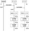
図9は、ビーコンメッシュ内のビーコンにおける時間同期の際の動作シーケンスの例を示す図である。ビーコンメッシュ内のビーコン10が電池駆動している場合、ビーコン10が動作する時間を短くすることで、ビーコン10で使用される時間あたりの消費電力量を減らすことが求められる。時間あたりの消費電力量を減らすことで、電池交換の頻度を下げることができる。しかし、ビーコン10が動作する時間帯をビーコンメッシュ内で合わせないと、信号の送受信を行うことが難しくなる。そこで、ビーコンメッシュ内の時刻同期を行うことが求められる。ここでは、制御装置20からの信号により、ビーコンメッシュ内のビーコン10の時刻同期を行うことについて説明する。
図9は、ビーコンメッシュ内のビーコンにおける時間同期の際の動作シーケンスの例を示す図である。ビーコンメッシュ内のビーコン10が電池駆動している場合、ビーコン10が動作する時間を短くすることで、ビーコン10で使用される時間あたりの消費電力量を減らすことが求められる。時間あたりの消費電力量を減らすことで、電池交換の頻度を下げることができる。しかし、ビーコン10が動作する時間帯をビーコンメッシュ内で合わせないと、信号の送受信を行うことが難しくなる。そこで、ビーコンメッシュ内の時刻同期を行うことが求められる。ここでは、制御装置20からの信号により、ビーコンメッシュ内のビーコン10の時刻同期を行うことについて説明する。
SQ2001では、制御装置20は、ビーコンメッシュ内のすべてのビーコン10に向けて、時刻同期の指示(司令、コマンド)を含む信号(時刻同期命令、時刻同期信号)を、ビーコンメッシュのビーコン10に向けて送信する。当該信号は、例えば、アドバタイズ信号(報知信号)である。また、制御装置20から送信される信号は、Bluetoothによるメッシュ通信で使用される10byte程度の所定のデータ信号であってもよい。メッシュ通信で使用される当該信号は、アドバタイズ信号よりも小さくてもよい。当該信号には、時刻同期の指示を示す情報が含まれる。制御装置20からの信号は、複数のビーコン10によって受信され得る。ここでは、制御装置20からの信号は、ビーコン10Eに受信されたとする。制御装置20は、当該信号をビーコンの無線標識として送信してもよい。時刻同期の指示には、時刻同期以外の指示等が、含まれてもよい。制御装置20は、あらかじめ定められたスケジュールに基づいて、時刻同期の指示を含む信号を送信してもよい。当該信号には、今回の信号を識別する識別情報が含まれてもよい。
制御装置20からの信号を受信したビーコン10Eは、当該信号の内容を確認する。ここでは、ビーコン10Eは、受信した信号に含まれる情報により、時刻同期信号であることを認識する。ビーコン10Eは、受信した信号に含まれる情報を、記憶部13に格納する。
SQ2002では、ビーコン10Eは、制御装置20からの信号を、周囲のビーコン10等に対して、送信する。また、ビーコン10Eは、制御装置20からの信号が以前に送信した信号と同一の信号である場合、当該信号を、送信しない。ここでは、当該信号は、ビーコン10Dによって受信されるとする。
ビーコン10Eからの信号を受信したビーコン10Dは、当該信号の内容を確認する。ここでは、ビーコン10Dは、受信した信号に含まれる情報により、時刻同期信号であることを認識する。ビーコン10Dは、受信した信号に含まれる情報を、記憶部13に格納する。
さらに、ビーコン10Dは、ビーコン10Eと同様に、ビーコン10Eからの信号を、周囲のビーコン10等に対して、送信する。また、ビーコン10Dは、制御装置20からの信号が以前に送信した信号と同一の信号である場合、当該信号を、送信しない。
SQ2003では、時刻同期信号を受信したビーコン10(ビーコン10D、ビーコン10E等)は、自身に内蔵される時計の時刻を所定の基準時刻(例えば、時刻0)に、設定する。ここで、時刻同期信号は、ビーコンメッシュ内を順次転送されるため、それぞれのビーコン10が時刻同期信号を受信するタイミングに、タイムラグが生じるが、ここで扱う時間スケールにおいては、各ビーコン10において、ほぼ同時に時刻同期信号を受信しているとみなすことができる。ビーコン10に内蔵される時計は、時刻をカウントする。
SQ2004では、ビーコン10は、自装置を所定時間スリープさせる。ビーコン10がスリープしている時間において、ビーコン10は信号の送受信を停止する。これにより、ビーコン10における消費電力を抑制することができる。
SQ2005では、ビーコン10は、SQ2004でスリープしてから所定時間経過すると、信号の送受信を所定時間行う。これにより、他のビーコン10と同じ時間帯で、信号の送受信をすることができる。
以後、各ビーコン10において、SQ2004及びSQ2005の処理が繰り返される。当該処理は、次の時刻同期信号を受信した場合に、停止される。ビーコン10がスリープする時間の長さや送受信する時間の長さは、あらかじめ決められていてもよいし、時刻同期信号において指定されてもよい。例えば、時刻同期信号が定期的に制御装置20から送信されることで、ビーコン10に内蔵される時計における個体差による時刻のずれを解消することができる。また、時刻同期信号が定期的に制御装置20から送信されることで、ビーコンメッシュ上に新たなビーコン10を追加した場合にも、時刻同期を行うことができる。また、新たなビーコン10の追加を認識した周辺のメッシュビーコン内のビーコン10が、新たなビーコン10に基準時刻からの経過時間を含む信号を送信して、時刻同期を行うようにしてもよい。さらに、新たなビーコン10に基準時刻からの経過時間を含む信号を送信したビーコン10の時計の時刻が間違っている可能性がある。ビーコン10の時計に間違った時刻を設定すると、他のビーコン10や制御装置20からの信号を受信できなくなることがある。そこで、ビーコン10が所定期間、制御装置20からの信号(時刻同期信号等)を受信しない場合、当該ビーコン10は、時計の時刻が間違っていると判断して、制御装置20からの信号を受信するまで、スリープせずに受信状態を維持するようにしてもよい。これにより、ビーコン10の時計の時刻がずれた場合でも、正しい時刻に合わせることができる。
これによって、ビーコンメッシュ内のビーコン10の時計の時刻を容易に同期することができる。時計の時刻が同期することで、ビーコンメッシュ内のビーコン10の送受信時間帯を一致させることができ、ビーコン10の省電力化を図ることができる。
《センサ情報のスキャニング》
ここでは、ビーコンメッシュ内のビーコンに関するセンサの情報を取得する際の動作について説明する。ビーコンメッシュのビーコン10では、Bluetoothのパケットの送受信を行うことができる。これを利用して、外部センサによるBluetoothのパケット(検出信号)を、ビーコンメッシュにおけるメッシュ通信を介して、制御装置20で収集することで、センサネットワークを構築することができる。外部センサによるBluetoothのパケットには、外部センサによる何らかの物理量等の検出結果が含まれる。また、ビーコンメッシュのビーコン10に内蔵される内部センサによる検出結果をBluetoothのパケットに載せて、制御装置20に収集させてもよい。このとき、図8のシーケンスにおいて、設定変更結果をビーコン10Dから制御装置20に送信するのと同様にして、各種センサによる検出結果(センサ情報等)を、制御装置20に集めることができる。各ビーコン10は、受信した外部センサによるBluetoothのパケットを、そのまま、制御装置20に向けて転送してもよい。
ここでは、ビーコンメッシュ内のビーコンに関するセンサの情報を取得する際の動作について説明する。ビーコンメッシュのビーコン10では、Bluetoothのパケットの送受信を行うことができる。これを利用して、外部センサによるBluetoothのパケット(検出信号)を、ビーコンメッシュにおけるメッシュ通信を介して、制御装置20で収集することで、センサネットワークを構築することができる。外部センサによるBluetoothのパケットには、外部センサによる何らかの物理量等の検出結果が含まれる。また、ビーコンメッシュのビーコン10に内蔵される内部センサによる検出結果をBluetoothのパケットに載せて、制御装置20に収集させてもよい。このとき、図8のシーケンスにおいて、設定変更結果をビーコン10Dから制御装置20に送信するのと同様にして、各種センサによる検出結果(センサ情報等)を、制御装置20に集めることができる。各ビーコン10は、受信した外部センサによるBluetoothのパケットを、そのまま、制御装置20に向けて転送してもよい。
各種センサやビーコン10から制御装置20に送信する情報は、データ量削減のために、検出結果に基づく値であってもよい。検出結果をフィルタリング等することによって、検出結果に基づく値のデータ量を小さくすることができる。また、制御装置20は、外部センサの送信電力、外部センサからの信号のビーコン10における受信電力を収集することで、外部センサの位置を算出するようにしてもよい。受信電力の大きさは、ビーコン10からの距離に依存するため、複数のビーコン10において外部センサからの信号を受信することができれば、複数のビーコン10から外部センサまでの距離が分かるため、外部センサの位置を算出することができる。
(実施形態の作用、効果)
本実施形態のビーコンメッシュにおけるビーコン10は、制御装置20から設定変更の指示を含む信号を受信する。ビーコン10は、設定変更の指示に基づいて、設定変更を行う。ビーコン10は、設定変更の結果を含む信号を、制御装置20に向けて、送信する。ビーコン10は、ビーコンメッシュにおけるメッシュ通信のパケットを利用して、設定変更の結果を送信することができる。
本実施形態のビーコンメッシュにおけるビーコン10は、制御装置20から設定変更の指示を含む信号を受信する。ビーコン10は、設定変更の指示に基づいて、設定変更を行う。ビーコン10は、設定変更の結果を含む信号を、制御装置20に向けて、送信する。ビーコン10は、ビーコンメッシュにおけるメッシュ通信のパケットを利用して、設定変更の結果を送信することができる。
本実施形態のビーコンメッシュにおける制御装置20は、ビーコンメッシュ内のビーコン10に向けて、時刻同期信号を受信する。時刻同期信号を受信した各ビーコン10は、内蔵される時計の時刻を基準時刻に設定する。各ビーコン10は、所定期間スリープする。各ビーコン10は、スリープする所定期間経過後、所定期間、信号の送受信を行う。これにより、ビーコン10における消費電力を抑制することができる。
本実施形態のビーコン10は、外部センサによる検出結果等を含む無線信号を受信して、制御装置20に向けて、送信することができる。制御装置20は、外部センサによる検出結果を、ビーコンメッシュを介して、取得することができる。
本発明は、上述した実施形態に限定されるものではなく、本発明の趣旨を逸脱しない範囲内において変更したり組み合わせたりすることができる。
〈コンピュータ読み取り可能な記録媒体〉
コンピュータその他の機械、装置(以下、コンピュータ等)に上記いずれかの機能を実現させるプログラムをコンピュータ等が読み取り可能な記録媒体に記録することができる。そして、コンピュータ等に、この記録媒体のプログラムを読み込ませて実行させることにより、その機能を提供させることができる。
コンピュータその他の機械、装置(以下、コンピュータ等)に上記いずれかの機能を実現させるプログラムをコンピュータ等が読み取り可能な記録媒体に記録することができる。そして、コンピュータ等に、この記録媒体のプログラムを読み込ませて実行させることにより、その機能を提供させることができる。
ここで、コンピュータ等が読み取り可能な記録媒体とは、データやプログラム等の情報を電気的、磁気的、光学的、機械的、または化学的作用によって蓄積し、コンピュータ等から読み取ることができる記録媒体をいう。このような記録媒体内には、CPU、メモリ等のコンピュータを構成する要素を設け、そのCPUにプログラムを実行させてもよい。
また、このような記録媒体のうちコンピュータ等から取り外し可能なものとしては、例えばフレキシブルディスク、光磁気ディスク、CD-ROM、CD-R/W、DVD、DAT、8mmテープ、メモリカード等がある。
また、コンピュータ等に固定された記録媒体としてハードディスクやROM等がある。
10 ビーコン
11 標識情報送信部
12 相互通信部
13 記憶部
20 制御装置
21 ビーコン通信部
22 情報取得部
23 記憶部
30 端末
31 標識情報送信部
32 相互通信部
33 記憶部
34 表示部
40 サーバ
41 通信部
42 演算部
43 記憶部
50 端末
51 通信部
52 記憶部
53 表示部
60 ネットワーク
11 標識情報送信部
12 相互通信部
13 記憶部
20 制御装置
21 ビーコン通信部
22 情報取得部
23 記憶部
30 端末
31 標識情報送信部
32 相互通信部
33 記憶部
34 表示部
40 サーバ
41 通信部
42 演算部
43 記憶部
50 端末
51 通信部
52 記憶部
53 表示部
60 ネットワーク
Claims (4)
- 所定の電波到達距離内において相互に通信可能であり、所定の信号を送受信する複数のビーコンであって、当該複数のビーコンのそれぞれは、少なくとも1つの他のビーコンの前記電波到達距離内に配置される複数のビーコンと、前記複数のビーコンのうちの少なくとも1つのビーコンと通信可能である制御装置とを含むシステムにおけるビーコンであって、
前記制御装置から発信された設定変更指示を含む信号を受信する受信手段と、
前記設定変更指示に基づいて、自装置の所定項目の設定値を変更する設定手段と、
前記設定手段により変更された設定値に基づく情報を含む信号を前記制御装置に向けて送信する送信手段と、
を備えるビーコン。 - 前記受信手段は、前記制御装置から発信された時刻同期指示を含む信号を受信し、
前記設定手段は、前記時刻同期指示に基づいて、自装置において動作する時計の時刻を基準時刻に設定し、
前記受信手段は、前記時計の時刻が、所定期間である場合に、他の装置から信号を受信し、
前記送信手段は、前記時計の時刻が、前記所定期間である場合に、他の装置に信号を送信する、
請求項1に記載のビーコン。 - 前記受信手段は、他のセンサによる物理量の検出結果を含む検出信号を受信し、
前記送信手段は、前記検出信号を含む信号を、前記制御装置に向けて送信する、
請求項1または2に記載のビーコン。 - 所定の電波到達距離内において相互に通信可能であり、所定の信号を送受信する複数のビーコンであって、当該複数のビーコンのそれぞれは、少なくとも1つの他のビーコンの前記電波到達距離内に配置される複数のビーコンと、前記複数のビーコンのうちの少なくとも1つのビーコンと通信可能である制御装置とを含むシステムにおけるビーコンであって、
前記制御装置から発信された時刻同期指示を含む信号を受信する受信手段と、
前記時刻同期指示に基づいて、自装置において動作する時計の時刻を基準時刻に設定する設定手段と、
前記時計の時刻が前記所定期間である場合に、他の装置に信号を送信する送信手段とを備え、
前記受信手段は、前記時計の時刻が、所定期間である場合に、他の装置から信号を受信する、
ビーコン。
Priority Applications (4)
| Application Number | Priority Date | Filing Date | Title |
|---|---|---|---|
| EP17864144.5A EP3534628A4 (en) | 2016-10-25 | 2017-10-17 | BAKE |
| SG11201903642SA SG11201903642SA (en) | 2016-10-25 | 2017-10-17 | Beacon |
| CN201780066093.XA CN109892005A (zh) | 2016-10-25 | 2017-10-17 | 信标 |
| US16/343,104 US10849047B2 (en) | 2016-10-25 | 2017-10-17 | Beacon |
Applications Claiming Priority (2)
| Application Number | Priority Date | Filing Date | Title |
|---|---|---|---|
| JP2016208690A JP2018074242A (ja) | 2016-10-25 | 2016-10-25 | ビーコン |
| JP2016-208690 | 2016-10-25 |
Publications (1)
| Publication Number | Publication Date |
|---|---|
| WO2018079342A1 true WO2018079342A1 (ja) | 2018-05-03 |
Family
ID=62023671
Family Applications (1)
| Application Number | Title | Priority Date | Filing Date |
|---|---|---|---|
| PCT/JP2017/037540 WO2018079342A1 (ja) | 2016-10-25 | 2017-10-17 | ビーコン |
Country Status (7)
| Country | Link |
|---|---|
| US (1) | US10849047B2 (ja) |
| EP (1) | EP3534628A4 (ja) |
| JP (1) | JP2018074242A (ja) |
| CN (1) | CN109892005A (ja) |
| SG (1) | SG11201903642SA (ja) |
| TW (1) | TW201819948A (ja) |
| WO (1) | WO2018079342A1 (ja) |
Families Citing this family (4)
| Publication number | Priority date | Publication date | Assignee | Title |
|---|---|---|---|---|
| JP7065758B2 (ja) * | 2018-12-13 | 2022-05-12 | 株式会社Where | ビーコンシステムの設定方法 |
| JP7281737B2 (ja) | 2019-06-05 | 2023-05-26 | パナソニックIpマネジメント株式会社 | 無線装置及び通信システム |
| EP3813389A1 (en) * | 2019-10-21 | 2021-04-28 | Carrier Corporation | Broadcast delivery techniques in a wireless network |
| KR102559284B1 (ko) * | 2021-11-29 | 2023-07-25 | 한국전자기술연구원 | 다중 주파수의 다중 비콘을 이용한 자차 실내 측위 시스템 및 방법 |
Citations (7)
| Publication number | Priority date | Publication date | Assignee | Title |
|---|---|---|---|---|
| WO2006001074A1 (ja) | 2004-06-25 | 2006-01-05 | Mitsubishi Denki Kabushiki Kaisha | 基地局間時刻同期方法、タイミングマスタ装置、および基地局 |
| JP2008306472A (ja) * | 2007-06-07 | 2008-12-18 | Hitachi Ltd | センサネットシステム、及びセンサノード |
| JP2009088750A (ja) * | 2007-09-28 | 2009-04-23 | Mitsubishi Electric Corp | 管理装置、無線端末、アドホックネットワークシステム、管理装置の設定変更プログラム、管理装置の設定変更方法、無線端末の設定変更プログラム及び無線端末の設定変更方法 |
| JP2010016576A (ja) * | 2008-07-03 | 2010-01-21 | Hitachi Electronics Service Co Ltd | ノード時刻同期方法及びセンサネットワークシステム |
| JP2012205108A (ja) * | 2011-03-25 | 2012-10-22 | Ohbayashi Corp | 無線計測制御システムおよび無線計測制御方法 |
| JP2015149526A (ja) | 2014-02-04 | 2015-08-20 | アプリックスIpホールディングス株式会社 | ビーコン装置管理システム、ビーコン装置管理方法及びサーバ |
| WO2016113884A1 (ja) * | 2015-01-15 | 2016-07-21 | 富士通株式会社 | 制御装置、制御方法、及び制御プログラム |
Family Cites Families (23)
| Publication number | Priority date | Publication date | Assignee | Title |
|---|---|---|---|---|
| GB9827989D0 (en) | 1998-12-19 | 1999-02-10 | Koninkl Philips Electronics Nv | Location beacon system |
| EP1267175A3 (en) | 2001-06-11 | 2003-10-15 | Hewlett-Packard Company | Location determination using location data items received by short-range communication |
| US7468969B2 (en) * | 2003-11-07 | 2008-12-23 | Interdigital Technology Corporation | Apparatus and methods for central control of mesh networks |
| US7367497B1 (en) | 2003-12-09 | 2008-05-06 | Jason Lester Hill | Electronic access control, tracking and paging system |
| SE528212C8 (sv) | 2004-07-16 | 2006-10-31 | Ericsson Telefon Ab L M | Bestämning av mogilterminalposition |
| JP4572698B2 (ja) | 2005-02-21 | 2010-11-04 | 日本電気株式会社 | 携帯端末装置、無線通信システム、位置情報算出方法及びプログラム |
| JP5015958B2 (ja) * | 2006-01-11 | 2012-09-05 | クゥアルコム・インコーポレイテッド | ピアツーピア通信においてidを提供するビーコン信号の符号化 |
| US20070184852A1 (en) | 2006-01-17 | 2007-08-09 | Johnson David W | Method and system for location of objects within a specified geographic area |
| JP2008175734A (ja) | 2007-01-19 | 2008-07-31 | Hitachi Ltd | 位置推定システム |
| JP2008199360A (ja) | 2007-02-14 | 2008-08-28 | Hitachi Ltd | 位置推定システム |
| US8787944B2 (en) | 2011-08-18 | 2014-07-22 | Rivada Research, Llc | Method and system for providing enhanced location based information for wireless handsets |
| JP6142497B2 (ja) | 2012-06-20 | 2017-06-07 | 株式会社リコー | 配信装置、通信端末及び配信システム |
| WO2015118938A1 (ja) | 2014-02-04 | 2015-08-13 | アプリックスIpホールディングス株式会社 | 電子機器管理システム、電子機器管理サーバ及び電子機器管理方法 |
| CN104020473A (zh) * | 2014-06-16 | 2014-09-03 | 罗宇 | 一种基于时间同步的便携式水下宽带扩频信标导航定位系统及方法 |
| CN104202295B (zh) * | 2014-07-25 | 2018-05-01 | 苏州寻息电子科技有限公司 | 基于信标节点的安全防护系统及其实现方法 |
| CN106662633B (zh) | 2014-08-12 | 2020-05-01 | 飞利浦灯具控股公司 | 用于定位移动设备的方法和装置 |
| US9867153B2 (en) * | 2014-12-18 | 2018-01-09 | Qualcomm Incorporated | Distributed synchronization of IoE devices |
| JP5792412B1 (ja) | 2014-12-26 | 2015-10-14 | 株式会社野村総合研究所 | ロケーション判定システム |
| CN107251623A (zh) | 2014-12-30 | 2017-10-13 | 飞利浦灯具控股公司 | 定位移动设备 |
| WO2016144085A1 (ko) | 2015-03-09 | 2016-09-15 | 엘지전자 주식회사 | 무선랜 시스템에서 nan 단말의 위치 측위 방법 및 이를 이용한 기기 |
| KR102386024B1 (ko) | 2015-10-15 | 2022-04-14 | 삼성전자 주식회사 | 사용자의 위치를 인식하는 사용자단말장치 및 방법 |
| JP6645920B2 (ja) | 2016-07-06 | 2020-02-14 | 富士通コンポーネント株式会社 | 無線通信装置 |
| JP6901069B2 (ja) * | 2016-09-26 | 2021-07-14 | 株式会社Where | 距離算出方法 |
-
2016
- 2016-10-25 JP JP2016208690A patent/JP2018074242A/ja active Pending
-
2017
- 2017-10-17 EP EP17864144.5A patent/EP3534628A4/en not_active Withdrawn
- 2017-10-17 CN CN201780066093.XA patent/CN109892005A/zh active Pending
- 2017-10-17 SG SG11201903642SA patent/SG11201903642SA/en unknown
- 2017-10-17 WO PCT/JP2017/037540 patent/WO2018079342A1/ja unknown
- 2017-10-17 US US16/343,104 patent/US10849047B2/en active Active
- 2017-10-24 TW TW106136460A patent/TW201819948A/zh unknown
Patent Citations (7)
| Publication number | Priority date | Publication date | Assignee | Title |
|---|---|---|---|---|
| WO2006001074A1 (ja) | 2004-06-25 | 2006-01-05 | Mitsubishi Denki Kabushiki Kaisha | 基地局間時刻同期方法、タイミングマスタ装置、および基地局 |
| JP2008306472A (ja) * | 2007-06-07 | 2008-12-18 | Hitachi Ltd | センサネットシステム、及びセンサノード |
| JP2009088750A (ja) * | 2007-09-28 | 2009-04-23 | Mitsubishi Electric Corp | 管理装置、無線端末、アドホックネットワークシステム、管理装置の設定変更プログラム、管理装置の設定変更方法、無線端末の設定変更プログラム及び無線端末の設定変更方法 |
| JP2010016576A (ja) * | 2008-07-03 | 2010-01-21 | Hitachi Electronics Service Co Ltd | ノード時刻同期方法及びセンサネットワークシステム |
| JP2012205108A (ja) * | 2011-03-25 | 2012-10-22 | Ohbayashi Corp | 無線計測制御システムおよび無線計測制御方法 |
| JP2015149526A (ja) | 2014-02-04 | 2015-08-20 | アプリックスIpホールディングス株式会社 | ビーコン装置管理システム、ビーコン装置管理方法及びサーバ |
| WO2016113884A1 (ja) * | 2015-01-15 | 2016-07-21 | 富士通株式会社 | 制御装置、制御方法、及び制御プログラム |
Non-Patent Citations (1)
| Title |
|---|
| See also references of EP3534628A4 |
Also Published As
| Publication number | Publication date |
|---|---|
| JP2018074242A (ja) | 2018-05-10 |
| EP3534628A1 (en) | 2019-09-04 |
| US20190320377A1 (en) | 2019-10-17 |
| US10849047B2 (en) | 2020-11-24 |
| CN109892005A (zh) | 2019-06-14 |
| EP3534628A4 (en) | 2020-03-11 |
| SG11201903642SA (en) | 2019-05-30 |
| TW201819948A (zh) | 2018-06-01 |
Similar Documents
| Publication | Publication Date | Title |
|---|---|---|
| WO2018079342A1 (ja) | ビーコン | |
| TWI739909B (zh) | 位置算出方法、距離算出方法、及信標 | |
| JP5476880B2 (ja) | 情報提供装置及び情報提供方法、コンピューター・プログラム、並びに無線通信装置 | |
| CN106416317B (zh) | 用于提供位置信息的方法和装置 | |
| JP6852856B2 (ja) | 制御装置、制御方法、制御プログラム | |
| US10051412B2 (en) | Locational information transmission system, locational information transmission apparatus, and information processing device | |
| US9173188B2 (en) | Communication apparatus, position information management system, and position information management method | |
| JP6816860B2 (ja) | 斜面崩壊検出方法 | |
| JP6801931B2 (ja) | 無線標識システムの制御方法、無線標識システム、及びビーコン | |
| EP2903352A1 (en) | Radio communication system | |
| JP2009087834A (ja) | 照度制御システム、およびそのプログラム | |
| WO2015098213A1 (ja) | 情報処理装置、情報処理方法、対象端末、通信方法およびプログラム | |
| JP5263318B2 (ja) | 位置情報認識システムおよび方法、ならびに携帯端末およびそのプログラム | |
| US10271167B2 (en) | Item management system | |
| JP2011035438A (ja) | センサ機能を有する無線端末機器、該端末機器の省電力化方法およびコンピュータプログラム | |
| JP6406995B2 (ja) | 無線テレメータシステム及び無線通信装置 | |
| JP6809676B2 (ja) | ビーコン、及び、サーバ | |
| JP2020035391A (ja) | 電柱監視システム、及び、電柱監視方法 | |
| WO2020256081A1 (ja) | 領域判定システム | |
| JP6653969B2 (ja) | 無線通信システム | |
| JP6199202B2 (ja) | 無線通信装置 | |
| JP2005051557A (ja) | 通信システム | |
| JP6584052B2 (ja) | 無線通信システム及び無線通信装置 |
Legal Events
| Date | Code | Title | Description |
|---|---|---|---|
| 121 | Ep: the epo has been informed by wipo that ep was designated in this application |
Ref document number: 17864144 Country of ref document: EP Kind code of ref document: A1 |
|
| NENP | Non-entry into the national phase |
Ref country code: DE |
|
| ENP | Entry into the national phase |
Ref document number: 2017864144 Country of ref document: EP Effective date: 20190527 |