WO2018079342A1 - Balise - Google Patents
Balise Download PDFInfo
- Publication number
- WO2018079342A1 WO2018079342A1 PCT/JP2017/037540 JP2017037540W WO2018079342A1 WO 2018079342 A1 WO2018079342 A1 WO 2018079342A1 JP 2017037540 W JP2017037540 W JP 2017037540W WO 2018079342 A1 WO2018079342 A1 WO 2018079342A1
- Authority
- WO
- WIPO (PCT)
- Prior art keywords
- beacon
- signal
- control device
- information
- beacons
- Prior art date
Links
Images

Classifications
-
- H—ELECTRICITY
- H04—ELECTRIC COMMUNICATION TECHNIQUE
- H04W—WIRELESS COMMUNICATION NETWORKS
- H04W56/00—Synchronisation arrangements
- H04W56/001—Synchronization between nodes
- H04W56/002—Mutual synchronization
-
- H—ELECTRICITY
- H04—ELECTRIC COMMUNICATION TECHNIQUE
- H04W—WIRELESS COMMUNICATION NETWORKS
- H04W40/00—Communication routing or communication path finding
- H04W40/24—Connectivity information management, e.g. connectivity discovery or connectivity update
- H04W40/244—Connectivity information management, e.g. connectivity discovery or connectivity update using a network of reference devices, e.g. beaconing
-
- H—ELECTRICITY
- H04—ELECTRIC COMMUNICATION TECHNIQUE
- H04W—WIRELESS COMMUNICATION NETWORKS
- H04W4/00—Services specially adapted for wireless communication networks; Facilities therefor
- H04W4/30—Services specially adapted for particular environments, situations or purposes
- H04W4/38—Services specially adapted for particular environments, situations or purposes for collecting sensor information
-
- H—ELECTRICITY
- H04—ELECTRIC COMMUNICATION TECHNIQUE
- H04W—WIRELESS COMMUNICATION NETWORKS
- H04W52/00—Power management, e.g. TPC [Transmission Power Control], power saving or power classes
- H04W52/02—Power saving arrangements
- H04W52/0209—Power saving arrangements in terminal devices
- H04W52/0261—Power saving arrangements in terminal devices managing power supply demand, e.g. depending on battery level
-
- H—ELECTRICITY
- H04—ELECTRIC COMMUNICATION TECHNIQUE
- H04W—WIRELESS COMMUNICATION NETWORKS
- H04W52/00—Power management, e.g. TPC [Transmission Power Control], power saving or power classes
- H04W52/04—TPC
- H04W52/38—TPC being performed in particular situations
- H04W52/46—TPC being performed in particular situations in multi hop networks, e.g. wireless relay networks
-
- H—ELECTRICITY
- H04—ELECTRIC COMMUNICATION TECHNIQUE
- H04W—WIRELESS COMMUNICATION NETWORKS
- H04W56/00—Synchronisation arrangements
- H04W56/001—Synchronization between nodes
-
- H—ELECTRICITY
- H04—ELECTRIC COMMUNICATION TECHNIQUE
- H04W—WIRELESS COMMUNICATION NETWORKS
- H04W84/00—Network topologies
- H04W84/02—Hierarchically pre-organised networks, e.g. paging networks, cellular networks, WLAN [Wireless Local Area Network] or WLL [Wireless Local Loop]
- H04W84/10—Small scale networks; Flat hierarchical networks
-
- H—ELECTRICITY
- H04—ELECTRIC COMMUNICATION TECHNIQUE
- H04W—WIRELESS COMMUNICATION NETWORKS
- H04W84/00—Network topologies
- H04W84/18—Self-organising networks, e.g. ad-hoc networks or sensor networks
Definitions
- the present invention relates to a beacon.
- beacon radio beacon
- Some beacons send information to mobile computers.
- some beacons for mobile computers use Bluetooth (registered trademark).
- Bluetooth registered trademark
- an information communication system in which a wireless communication monitoring device transmits beacon transmission level information to a beacon and adjusts the beacon transmission level for a beacon that transmits information to a moving body such as an automobile including a receiver. Has been.
- beacon mesh There is a technology that configures a beacon mesh with multiple beacons.
- Beacons constituting a beacon mesh (also referred to as mesh-type beacons) have a function of communicating with other beacons installed within the reach of radio waves and form a multi-hop wireless network as a whole.
- the mesh type beacon transmits a radio beacon including its own identification information to other beacons.
- the beacon mesh can be connected to other networks via a gateway.
- the gateway can individually send a setting change command to the beacons in the beacon mesh. However, it is difficult for the gateway to recognize the result of the setting change in each beacon.
- An object of the present invention is to provide a technology for controlling a beacon in a mesh beacon.
- the first aspect is A plurality of beacons that can communicate with each other within a predetermined radio wave reach and transmit / receive a predetermined signal, each of the beacons being disposed within the radio wave reach of at least one other beacon.
- a beacon in a system including a plurality of beacons and a control device capable of communicating with at least one beacon of the plurality of beacons, Receiving means for receiving a signal including a setting change instruction transmitted from the control device; Based on the setting change instruction, setting means for changing a setting value of a predetermined item of the own device; Transmitting means for transmitting a signal including information based on the setting value changed by the setting means to the control device; Beacon with
- the disclosed aspect may be realized by a program being executed by an information processing apparatus. That is, the disclosed configuration can be specified as a program for causing the information processing apparatus to execute the processing executed by each unit in the above-described aspect, or a computer-readable recording medium on which the program is recorded. Further, the disclosed configuration may be specified by a method in which the information processing apparatus executes the process executed by each of the above-described units. The configuration of the disclosure may be specified as a system including an information processing apparatus that performs the processing executed by each of the above-described units.
- the beacon in the mesh beacon can be controlled.
- FIG. 1 is a diagram illustrating a configuration example of a system according to the embodiment.
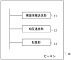
- FIG. 2 is a diagram illustrating an example of functional blocks of the beacon 10.
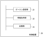
- FIG. 3 is a diagram illustrating an example of functional blocks of the control device 20.
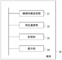
- FIG. 4 is a diagram illustrating an example of functional blocks of the terminal 30.
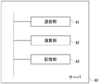
- FIG. 5 is a diagram illustrating an example of functional blocks of the server 40.
- FIG. 6 is a diagram illustrating an example of functional blocks of the terminal 50.
- FIG. 7 is a diagram illustrating a hardware configuration example of the information processing apparatus.
- FIG. 8 is a diagram illustrating an example of an operation sequence when changing the setting of the beacon in the beacon mesh from the control device.
- FIG. 9 is a diagram illustrating an example of an operation sequence in time synchronization in a beacon in a beacon mesh.
- FIG. 1 is a diagram illustrating a configuration example of a system according to the embodiment.
- the radio beacon transmission device in addition to the radio beacon transmitted and received for positioning or the like, the radio beacon transmission device is referred to as a beacon.
- the system according to the present embodiment includes a beacon 10 (in FIG. 1, beacon 10A to beacon 10E), a control device 20, a terminal 30, a server 40, and a terminal 50.
- the terminal 30 exists at a position where a signal from any one of the beacons 10 can be received.
- the terminal 30 is carried by a user or attached to a predetermined object.
- the control device 20, the server 40, and the terminal 50 are connected via a network 60 such as the Internet.
- the terminal 30 may be connected to the network 60.
- Beacon 10A to beacon 10E form a multi-hop wireless network.
- the beacon 10 transmits a wireless sign including identification information and transmission date / time.
- the beacon 10 according to the present embodiment has a function of communicating with other beacons 10 installed within the reach of radio waves, and forms a multi-hop wireless network as a whole.
- each of the plurality of beacons is arranged within the radio wave reach of at least one other beacon.
- the beacon 10 receives the identification information of the terminal 30 from the terminal 30.
- the beacon 10 transmits the identification information of the beacon 10 itself, the reception intensity of the signal from the terminal 30, information indicating the state of the beacon 10 and the like to the other beacons 10 together with the identification information from the terminal 30.
- the information indicating the state or the like of the beacon 10 may include a division method received from another beacon 10.
- a plurality of beacons that can communicate with each other are collectively referred to as a beacon mesh.
- the beacon 10 has, for example, a microcontroller and an antenna, and realizes various functions by cooperation of them.
- the beacon 10 can include various sensors as internal sensors.
- the various sensors are, for example, a camera, a microphone, a thermometer, a hygrometer, an optical sensor, an infrared sensor, an electric meter, a gas meter, a water meter, a measuring instrument, and the like. Images, images, sounds, values, etc. are detected by various sensors.
- Various sensors may be connected to the beacon 10 as external sensors.
- the beacon 10 can measure the remaining amount of the battery built in itself.
- the external sensor may have a wireless communication function using Bluetooth or the like. At this time, the external sensor can transmit a detection result or the like on a Bluetooth packet.
- the control device 20 is a device that centrally controls the operations of the plurality of beacons 10. For example, the control device 20 transmits specific information including identification information for specifying any of the plurality of beacons 10 and predetermined information to the surrounding beacons 10. On the other hand, when the beacon 10 relays the received specific information to the surrounding beacons 10 and receives specific information including identification information indicating itself, the beacon 10 performs a predetermined process based on the specific information.
- the specific information may include information for controlling the operation of the beacon 10, for example.
- the control device 20 operates as a gateway that connects the beacon mesh and the network 60.
- the terminal 30 receives a wireless sign from the beacon 10.
- the terminal 30 transmits identification information for identifying the terminal 30 itself to the beacon 10. 1 shows one terminal 30, the number of terminals 30 is not limited to one.
- the terminal 30 may have a function as the beacon 10.
- the terminal 30 may function as one beacon 10 in the beacon mesh.
- the terminal 30 may include an internal sensor or be connected to an external sensor.
- the terminal 30 may be carried by the user or attached to a movable object.
- the server 40 transmits a set of data such as identification information and transmission date / time of the beacon 10 included in the radio beacon from the terminal 30, reception date / time of the radio beacon at the terminal 30, and identification information of the terminal 30 via the beacon mesh. get.
- the server 40 can acquire information indicating the state of the beacon 10 and the like. Further, the server 40 outputs the acquired information to the terminal 50 or the like via the network 60.
- the server 40 may output information or the like according to the terminal 30.
- the terminal 50 is connected to the network 60 and receives information on the terminal 30 from the server 40. 1 shows one terminal 50, the number of terminals 50 is not limited to one.
- FIG. 2 is a diagram illustrating an example of functional blocks of the beacon 10 according to the embodiment.
- a plurality of beacons 10 are installed in a station premises such as a subway, an underground mall, a building, a tunnel, or the like at intervals equal to or shorter than a predetermined radio wave reachable distance. For example, it shall be installed at intervals of about 10 m depending on the installation location.
- the beacon 10 includes a sign information transmission unit 11, a mutual communication unit 12, and a storage unit 13.
- the beacon information transmission unit 11 transmits a radio beacon including identification information for identifying the beacon 10 based on the information held in the storage unit 13 and notifies the reception side device of proximity.
- the wireless sign may include date and time information indicating a transmission time. Specifically, a technique such as BLE (Bluetooth Low Energy) can be used, and wireless sign broadcast communication may be performed.
- BLE Bluetooth Low Energy
- the mutual communication unit 12 transmits and receives information to and from other beacons 10, terminals 30, and the control device 20. For example, mutual communication may be performed based on a profile such as GATT in BLE.
- the mutual communication unit 12 may perform connection-type communication.
- the mutual communication unit 12 receives specific information including identification information of another beacon 10
- the mutual communication unit 12 relays the specific information to surrounding beacons 10.
- specific information including identification information indicating itself is received, the specific information is stored in the storage unit 13 and a predetermined process is performed based on the specific information.
- the mutual communication unit 12 receives a signal including the terminal ID of the terminal 30 from the terminal 30.
- the mutual communication unit 12 measures the reception strength of the received signal.
- the mutual communication unit 12 stores the information included in the received signal in association with the reception intensity of the signal in the storage unit 13.
- the mutual communication unit 12 may respond to the control device 20 via the beacon mesh network with the information held in the storage unit 13 in response to a request from the control device 20.
- Information stored in the storage unit 13 may include information acquired by an internal sensor or an external sensor of the beacon 10.
- unique identification information may be assigned in advance to information such as specific information transmitted and received between the beacons 10.
- the mutual communication unit 12 stores the identification information of the transferred information once in the storage unit 13, and when the information is transferred, the identification information of the information transferred to the storage unit 13 in the past. If it is information transferred in the past, it is not necessary to transfer the information. Thereby, it can be avoided that the same information continues to be transferred in the beacon mesh.
- the storage unit 13 is a nonvolatile memory, and is realized by, for example, an EEPROM (ElectricallyrErasable Programmable Read-Only-Memory) such as a flash memory included in a microprocessor.
- the storage unit 13 stores predetermined identification information of the beacon 10, a set value of the radio wave intensity when the sign information transmission unit 11 transmits a wireless sign, and the like.
- the storage unit 13 stores information included in the received signal, reception intensity of the signal, and the like.
- FIG. 3 is a diagram illustrating an example of functional blocks of the control device 20 according to the embodiment.
- the control device 20 is, for example, a general computer, and includes a beacon communication unit 21, an information acquisition unit 22, and a storage unit 23.
- the beacon communication unit 21 performs bidirectional communication with the beacon 10. That is, the specific information mentioned above is transmitted, or life / death information or information held by the beacon 10 is received from the beacon 10.
- the control device 20 may be connected to one beacon 10 by wire or the like so as to be communicable.
- the information acquisition unit 22 acquires predetermined information from a device (not shown) via the network 60 such as the Internet or a dedicated line.
- the information acquisition unit 22 causes the beacon communication unit 21 to transmit specific information and change the setting of the beacon 10 based on an input from a user who operates the control device 20 or the like.
- the information acquisition unit 22 may acquire information from each beacon 10.
- identification information corresponding to all the beacons 10 may be included in the specific information, and the beacon 10 may broadcast the same specific information only once.
- the beacon 10 increments the number of hops every time the setting change information is transferred so that the specific information includes the number of hops indicating the number of times that the beacon mesh is transferred on the beacon mesh network. The specific information may be deleted from the beacon mesh.
- the storage unit 23 is realized by, for example, a hard disk drive (HDD), a solid state drive (SSD), a flash memory, or the like.
- storage part 23 memorize
- FIG. 4 is a diagram illustrating an example of functional blocks of the terminal 30 according to the embodiment.
- the terminal 30 is a computer such as a smartphone or a slate PC, for example, and includes a sign information transmission unit 31, a mutual communication unit 32, a storage unit 33, and a display unit 34.
- the sign information transmission unit 31 and the mutual communication unit 32 are realized by, for example, application software (also called a program) installed in the terminal 30 using the communication function of the terminal 30.
- the beacon information transmission unit 31 transmits a radio beacon including identification information for identifying the terminal 30 as the beacon 10 based on the information held in the storage unit 33, and notifies the reception side device of proximity. I do.
- the wireless sign may include date and time information indicating a transmission time. Specifically, a technique such as BLE (Bluetooth Low Energy) can be used, and wireless sign broadcast communication may be performed.
- the radio beacon (information) including the identification information of the terminal 30 transmitted by the terminal 30 can be received by a plurality of beacons.
- the mutual communication unit 32 transmits and receives information to and from other beacons 10, the terminals 30, and the control device 20. For example, mutual communication may be performed based on a profile such as GATT in BLE.
- the mutual communication unit 32 may perform connection-type communication.
- the mutual communication unit 32 receives specific information including identification information of another beacon 10
- the mutual communication unit 32 relays the specific information to surrounding beacons 10.
- specific information including identification information indicating itself is received, the specific information is stored in the storage unit 33 and predetermined processing is performed based on the specific information.
- the mutual communication 32 may respond to the control device 20 via the beacon mesh network with information held in the storage unit 33 in response to a request from the control device 20.
- the mutual communication unit 32 receives the radio beacon transmitted by the beacon 10 and stores it in the storage unit 33.
- the storage unit 33 is a volatile memory or a nonvolatile memory. For example, it is realized by a RAM (Random Access Memory), a ROM (Read Only Memory), an EEPROM such as a flash memory, or the like.
- the mutual communication unit 32 transmits the wireless label stored in the storage unit 33, the reception date and time of the wireless label, and the identification information for specifying the terminal 30 to the server 40 via the beacon mesh.
- the identification information for specifying the terminal 30 may use an ID provided by an OS (Operating System) such as a smartphone, or the server 40 may provide unique identification information for the application software of the terminal 30. May be issued.
- OS Operating System
- the storage unit 33 is realized by, for example, a hard disk drive (HDD), a solid state drive (SSD), a flash memory, or the like.
- the storage unit 33 stores identification information for identifying the terminal 30 from the terminal 30.
- storage part 33 memorize
- the display unit 34 displays the position information and other information stored in the storage unit 33 on a monitor provided in the terminal 30.
- FIG. 5 is a diagram illustrating an example of functional blocks of the information providing server 40 according to the embodiment.
- the server 40 is, for example, a stationary computer, and includes a communication unit 41, a calculation unit 42, and a storage unit 43.
- the control device 20 and the server 40 may be integrated to operate as one control device.
- the communication unit 41 transmits / receives information to / from the control device 20 and the terminal 50 via the network 60 such as the Internet. As described above, the communication unit 41 receives information including the identification information of the terminal 30 from the terminal 30 via the beacon mesh and the control device 20 and stores the information in the storage unit 43.
- the calculation unit 42 performs a predetermined calculation based on information from the beacon 10 or the terminal 30. For example, the calculation unit 42 calculates the position where the terminal 10 is present.
- the storage unit 43 includes, for example, an HDD, an SSD, a flash memory, and the like, and receives information from the terminal 30 via the beacon mesh and the control device 20, and information indicating the position of the terminal 30 calculated based on the information. In addition, information related to the vicinity of the position where the beacon 10 is installed may be stored in advance.
- storage part 43 matches and stores the identification information (beacon ID) of each beacon 10 of a beacon mesh, and the positional information which shows the presence position of each beacon.
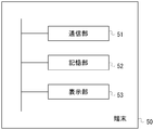
- FIG. 6 is a diagram illustrating an example of functional blocks of the terminal 50 according to the embodiment.
- the terminal 50 is a computer, for example, and includes a communication unit 51, a storage unit 52, and a display unit 53.
- the communication unit 51 transmits and receives information to and from the server 40 via a network 60 such as the Internet. As described above, for example, the communication unit 51 receives information including the position information of the terminal 30 from the server 40 and stores the information in the storage unit 52.
- the storage unit 52 includes, for example, an HDD, an SSD, a flash memory, or the like, and stores information received from the server 40.
- the storage unit 52 stores the position information of the terminal 30 received from the server 40.
- the storage unit 52 may store a map including an area (such as an underground mall) where the beacon 10 of the beacon mesh is installed.
- the display unit 53 displays the position information of the terminal 30 and other information stored in the storage unit 52 on a monitor provided in the terminal 50.
- the control device 20, the terminal 30, and the terminal 50 include a dedicated or general-purpose computer such as a smartphone, a mobile phone, a tablet terminal, a car navigation device, a PDA (Personal Digital Assistant), and a PC (Personal Computer), or a computer. This can be realized by using the electronic equipment.
- the server 40 can be realized using a dedicated or general-purpose computer such as a PC or a work station (WS), or an electronic device equipped with the computer.
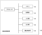
- FIG. 7 is a diagram illustrating a hardware configuration example of the information processing apparatus.
- the information processing apparatus 90 shown in FIG. 7 has a general computer configuration.
- the control device 20, the terminal 30, the server 40, and the terminal 50 are realized by an information processing device 90 as shown in FIG.
- the information processing apparatus 90 includes a processor 91, a memory 92, a storage unit 93, an input unit 94, an output unit 95, and a communication control unit 96. These are connected to each other by a bus.
- the memory 92 and the storage unit 93 are computer-readable recording media.
- the hardware configuration of the information processing apparatus is not limited to the example illustrated in FIG. 7, and components may be omitted, replaced, or added as appropriate.
- a processor 91 loads a program stored in a recording medium into a work area of the memory 92 and executes the program, and each component is controlled through execution of the program, thereby meeting a predetermined purpose. Function can be realized.
- the processor 91 is, for example, a CPU (Central Processing Unit) or a DSP (Digital Signal Processor).
- CPU Central Processing Unit
- DSP Digital Signal Processor
- the memory 92 includes, for example, a RAM (Random Access Memory) and a ROM (Read Only Memory).
- the memory 92 is also called a main storage device.
- the storage unit 93 is, for example, an EPROM (Erasable Programmable ROM), a hard disk drive (HDD, Hard Disk Drive), or a solid state drive (SSD, Solid State Drive).
- the storage unit 93 can include a removable medium, that is, a portable recording medium.
- the removable medium is, for example, a USB (Universal Serial Bus) memory or a disc recording medium such as a CD (Compact Disc) or a DVD (Digital Versatile Disc).
- the storage unit 93 is also called a secondary storage device.
- the storage unit 93 stores various programs, various data, and various tables in a recording medium in a readable and writable manner.
- the storage unit 93 stores an operating system (Operating System: OS), various programs, various tables, and the like.
- Information stored in the storage unit 93 may be stored in the memory 92.
- information stored in the memory 92 may be stored in the storage unit 93.
- the operating system is software that mediates between software and hardware, manages memory space, manages files, manages processes and tasks, and so on.
- the operating system includes a communication interface.
- the communication interface is a program for exchanging data with other external devices connected via the communication control unit 96. Examples of the external device include other information processing devices and external storage devices.
- the input unit 94 includes a keyboard, a pointing device, a wireless remote controller, a touch panel, and the like.
- the input unit 94 may include a video / image input device such as a camera, and an audio input device such as a microphone.
- the output unit 95 includes a display device such as a CRT (Cathode Ray Tube) display, an LCD (Liquid Crystal Display), a PDP (Plasma Display Panel), an EL (Electroluminescence) panel, and an output device such as a printer.
- the output unit 95 can include an audio output device such as a speaker.
- the communication control unit 96 is connected to another device and controls communication between the information processing device 90 and the other device.
- the communication control unit 96 is a wireless communication circuit for wireless communication such as a LAN (Local Area Network) interface board, Bluetooth (registered trademark), or a communication circuit for telephone communication.
- the LAN interface board and the wireless communication circuit are connected to a network such as the Internet.
- the computer that realizes the control device 20, the terminal 30, the server 40, and the terminal 50 implements each function by the processor loading and executing the program stored in the secondary storage device to the main storage device.
- the storage unit of each device is provided in a storage area of the main storage device or the secondary storage device.
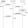
- FIG. 8 is a diagram illustrating an example of an operation sequence when changing the setting of the beacon in the beacon mesh from the control device.
- the control device 20 changes the setting of the beacon 10.
- Each beacon 10 of the beacon mesh is installed in a predetermined space such as an underground mall or a tunnel. All beacons 10 are installed at positions where they can communicate with any other beacon 10. Further, at least one beacon 10 is installed at a position where it can communicate with the control device 20. It is assumed that the terminal 30 is present at a position where a radio beacon from at least one beacon 10 can be received.
- the control device 20 transmits a signal including an instruction (command, command) for changing the setting of the beacon 10D toward the beacon 10 of the beacon mesh including the beacon 10D.
- the signal is, for example, an advertisement signal (notification signal).
- the signal transmitted from the control device 20 may be a predetermined data signal of about 10 bytes used in mesh communication by Bluetooth.
- the signal used in mesh communication may be smaller than the advertise signal.
- the signal includes identification information for identifying the beacon 10D.
- a signal from the control device 20 may be received by a plurality of beacons 10. Here, it is assumed that the signal from the control device 20 is received by the beacon 10E.
- the control device 20 may transmit the signal as a beacon radio indicator.
- the instruction to change the setting may include raising / lowering the output, starting / stopping the output, detecting the signal reception intensity, adjusting the clock, detecting the remaining battery level, detecting various situations, and the like.
- Control device 20 may transmit a signal including an instruction to change the setting of beacon 10 other than beacon 10D.
- the control device 20 may transmit a signal including a setting change instruction based on a predetermined schedule.
- the beacon 10E that has received the signal from the control device 20 confirms the content of the signal.
- the beacon 10E confirms whether or not the information included in the received signal includes its own identification information and an instruction to change its setting. Here, it is assumed that the signal does not include identification information of the beacon 10E.
- the beacon 10E stores information included in the received signal in the storage unit 13.
- beacon 10E transmits a signal from control device 20 to surrounding beacons 10 and the like. Moreover, when the signal from the control apparatus 20 is the same signal as the signal transmitted previously, the beacon 10E does not transmit the signal. Here, it is assumed that the signal is received by the beacon 10D.
- the beacon 10D that has received the signal from the beacon 10E confirms the content of the signal.
- the beacon 10D confirms whether or not the information included in the received signal includes its own identification information and an instruction to change its setting.
- the signal includes identification information of the beacon 10D.
- the beacon 10D stores information included in the received signal in the storage unit 13.
- the beacon 10D when the beacon 10D recognizes that its own identification information is included in the received signal, the beacon 10D confirms the setting change instruction included in the received signal.
- the beacon 10D changes the setting of the beacon 10D in accordance with the setting change instruction.
- the setting change instruction is, for example, raising or lowering the output. At this time, the beacon 10D increases or decreases the transmission output setting value (transmission power) by one step.
- the setting change instruction may include output start / stop, clock adjustment, signal reception intensity detection, battery remaining amount detection, detection of various situations, and the like.
- the setting change instruction is recognized in the beacon 10 by, for example, a bit value at a predetermined position in the signal, which is determined in advance between the control device 20 and each beacon 10.
- the beacon 10D transmits a signal including information on the result of the setting change to the control device 20.
- the setting change result is, for example, an output set value after the setting change, reception intensity, remaining battery level, various meter values, detection value, and the like.
- the setting change result may be a value based on the output setting value after changing the setting, the received intensity, the remaining battery level, the values of various meters, the detection value, etc. in order to reduce the data amount.
- the signal is, for example, an advertisement signal (notification signal).
- the signal may be, for example, a small data signal of about 10 bytes used in Bluetooth mesh communication.
- the signal may include identification information for identifying the control device 20 as information indicating that the control device 20 is addressed.
- the signal may include identification information for identifying the control device 20 as information indicating the beacon 10D that is the transmission source of the signal.
- the result of the setting change is expressed by, for example, a bit value at a predetermined position in the signal, which is determined in advance between the control device 20 and each beacon 10.
- the signal is received by the beacon 10E.
- the beacon 10E that has received the signal from the beacon 10D confirms the content of the signal.
- the beacon 10E confirms whether or not the information included in the received signal includes its own identification information and an instruction to change its setting. Here, it is assumed that the signal does not include identification information of the beacon 10E.
- the beacon 10E stores information included in the received signal in the storage unit 13.
- beacon 10E transmits a signal from beacon 10D to surrounding beacons 10 and the like. Moreover, beacon 10E does not transmit the said signal, when the said signal from beacon 10D is the same signal as the signal transmitted previously. Here, it is assumed that the signal is received by the control device 20.
- the control device 20 that has received the signal from the beacon 10E confirms the content of the signal.
- the control device 20 confirms whether the information included in the received signal includes its own identification information or the like. Here, it is assumed that the signal includes identification information of the control device 20.
- the control device 20 stores information included in the received signal in the storage unit 23.
- the control device 20 confirms information included in the signal received from the beacon 10E. Based on the information, the control device 20 can recognize the setting change result for the setting change instruction performed on the beacon 10D.
- the control device 20 can instruct setting change for the beacon 10D using a data signal used in mesh communication by Bluetooth. Moreover, the control apparatus 20 can receive the setting change result from beacon 10D, and can confirm the content of a setting change. For example, if a transmission arrival confirmation / retransmission request such as a 3-way handshake is made as in TCP, it is possible to confirm whether the packet has been correctly communicated and the setting has been changed. This leads to an increase in the number of communication efficiency.
- the control device 20 can recognize the setting change result while suppressing an increase in the amount of the signal.
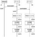
- FIG. 9 is a diagram illustrating an example of an operation sequence in time synchronization in a beacon in a beacon mesh.
- the beacon 10 in the beacon mesh is battery-powered, it is required to reduce the power consumption per hour used in the beacon 10 by shortening the time during which the beacon 10 operates. By reducing the power consumption per hour, the frequency of battery replacement can be lowered.
- the time zone in which the beacon 10 operates is matched in the beacon mesh, it becomes difficult to transmit and receive signals. Therefore, it is required to perform time synchronization within the beacon mesh.
- performing time synchronization of the beacon 10 in the beacon mesh by a signal from the control device 20 will be described.
- the control device 20 directs a signal (time synchronization command, time synchronization signal) including a time synchronization instruction (command, command) to all the beacons 10 in the beacon mesh to the beacon 10 of the beacon mesh.
- the signal is, for example, an advertisement signal (notification signal).
- the signal transmitted from the control device 20 may be a predetermined data signal of about 10 bytes used in mesh communication by Bluetooth.
- the signal used in mesh communication may be smaller than the advertise signal.
- the signal includes information indicating a time synchronization instruction.
- a signal from the control device 20 may be received by a plurality of beacons 10. Here, it is assumed that the signal from the control device 20 is received by the beacon 10E.
- the control device 20 may transmit the signal as a beacon radio indicator.
- the time synchronization instruction may include an instruction other than time synchronization.
- the control device 20 may transmit a signal including a time synchronization instruction based on a predetermined schedule.
- the signal may include identification information for identifying the current signal.
- the beacon 10E that has received the signal from the control device 20 confirms the content of the signal.
- the beacon 10E recognizes that it is a time synchronization signal from the information included in the received signal.
- the beacon 10E stores information included in the received signal in the storage unit 13.
- the beacon 10E transmits a signal from the control device 20 to the surrounding beacons 10 and the like. Moreover, when the signal from the control apparatus 20 is the same signal as the signal transmitted previously, the beacon 10E does not transmit the signal. Here, it is assumed that the signal is received by the beacon 10D.
- the beacon 10D that has received the signal from the beacon 10E confirms the content of the signal.
- beacon 10D recognizes that it is a time synchronous signal from the information contained in the received signal.
- the beacon 10D stores information included in the received signal in the storage unit 13.
- the beacon 10D transmits a signal from the beacon 10E to the surrounding beacons 10 and the like, like the beacon 10E. Moreover, beacon 10D does not transmit the said signal, when the signal from the control apparatus 20 is the same signal as the signal transmitted previously.
- the beacon 10 (beacon 10D, beacon 10E, etc.) that has received the time synchronization signal sets the time of the clock built in itself to a predetermined reference time (for example, time 0).
- a predetermined reference time for example, time 0
- a time lag occurs at the timing when each beacon 10 receives the time synchronization signal, but in the time scale handled here, in each beacon 10, It can be considered that the time synchronization signal is received almost simultaneously.
- a clock built in the beacon 10 counts time.
- the beacon 10 sleeps its own device for a predetermined time. During the time when the beacon 10 is sleeping, the beacon 10 stops signal transmission / reception. Thereby, the power consumption in the beacon 10 can be suppressed.
- the beacon 10 performs signal transmission / reception for a predetermined time when a predetermined time elapses after sleeping in SQ2004. Thereby, transmission and reception of signals can be performed in the same time zone as other beacons 10.
- each beacon 10 Thereafter, in each beacon 10, the processes of SQ2004 and SQ2005 are repeated. This process is stopped when the next time synchronization signal is received.
- the length of time for which the beacon 10 sleeps and the length of time for transmission and reception may be determined in advance or may be specified in the time synchronization signal.
- the time synchronization signal is periodically transmitted from the control device 20, whereby the time lag due to the individual difference in the timepiece incorporated in the beacon 10 can be eliminated.
- time synchronization can be performed even when a new beacon 10 is added to the beacon mesh by periodically transmitting a time synchronization signal from the control device 20.
- the beacon 10 in the surrounding mesh beacon which recognized the addition of the new beacon 10 may transmit a signal including the elapsed time from the reference time to the new beacon 10 to perform time synchronization. Furthermore, there is a possibility that the time of the clock of the beacon 10 that has transmitted a signal including the elapsed time from the reference time to the new beacon 10 is incorrect. If an incorrect time is set in the clock of the beacon 10, signals from other beacons 10 and the control device 20 may not be received. Therefore, when the beacon 10 does not receive a signal (time synchronization signal or the like) from the control device 20 for a predetermined period, the beacon 10 determines that the time of the clock is incorrect and receives the signal from the control device 20. Until then, the reception state may be maintained without going to sleep. Thereby, even when the time of the clock of the beacon 10 is deviated, it can be adjusted to the correct time.
- the beacon 10 of the beacon mesh can transmit and receive Bluetooth packets.
- a sensor network can be constructed by collecting Bluetooth packets (detection signals) from external sensors by the control device 20 via mesh communication in a beacon mesh.
- the Bluetooth packet by the external sensor includes a detection result of some physical quantity by the external sensor.
- the detection result by the internal sensor incorporated in the beacon 10 of the beacon mesh may be placed on the Bluetooth packet and collected by the control device 20.
- detection results (sensor information and the like) by various sensors can be collected in the control device 20 in the same manner as the setting change result is transmitted from the beacon 10 ⁇ / b> D to the control device 20.
- Each beacon 10 may forward the received Bluetooth packet from the external sensor to the control device 20 as it is.
- the information transmitted from the various sensors and beacons 10 to the control device 20 may be a value based on the detection result in order to reduce the amount of data. By filtering the detection result, the data amount of the value based on the detection result can be reduced.
- the control device 20 may calculate the position of the external sensor by collecting the transmission power of the external sensor and the reception power of the signal from the external sensor in the beacon 10. Since the magnitude of the received power depends on the distance from the beacon 10, if the signals from the external sensor can be received by the plurality of beacons 10, the distance from the plurality of beacons 10 to the external sensor can be known. Can be calculated.
- the beacon 10 in the beacon mesh of this embodiment receives a signal including a setting change instruction from the control device 20.
- the beacon 10 changes the setting based on the setting change instruction.
- the beacon 10 transmits a signal including the setting change result to the control device 20.
- the beacon 10 can transmit the result of the setting change by using a packet of mesh communication in the beacon mesh.
- the control device 20 in the beacon mesh of the present embodiment receives the time synchronization signal toward the beacon 10 in the beacon mesh.
- Each beacon 10 that has received the time synchronization signal sets the time of the built-in clock as the reference time.
- Each beacon 10 sleeps for a predetermined period.
- Each beacon 10 transmits and receives signals for a predetermined period after a predetermined period of sleep. Thereby, the power consumption in the beacon 10 can be suppressed.
- the beacon 10 can receive a wireless signal including a detection result by an external sensor and transmit it to the control device 20.
- the control apparatus 20 can acquire the detection result by an external sensor via a beacon mesh.
- Computer-readable recording medium A program for causing a computer or other machine or device (hereinafter, a computer or the like) to realize any of the above functions can be recorded on a recording medium that can be read by the computer or the like.
- the function can be provided by causing a computer or the like to read and execute the program of the recording medium.
- a computer-readable recording medium is a recording medium that stores information such as data and programs by electrical, magnetic, optical, mechanical, or chemical action and can be read from a computer or the like.
- elements constituting a computer such as a CPU and a memory may be provided to cause the CPU to execute a program.
- recording media that can be removed from a computer or the like, there are, for example, a flexible disk, a magneto-optical disk, a CD-ROM, a CD-R / W, a DVD, a DAT, an 8 mm tape, and a memory card.
- a hard disk a ROM, etc. as a recording medium fixed to a computer or the like.
Landscapes
- Engineering & Computer Science (AREA)
- Computer Networks & Wireless Communication (AREA)
- Signal Processing (AREA)
- Mobile Radio Communication Systems (AREA)
- Radio Relay Systems (AREA)
Abstract
L'objectif de la présente invention est de commander une balise dans une balise maillée. Un système contient une pluralité de balises qui sont capables de communiquer les unes avec les autres à l'intérieur d'une distance d'atteinte d'onde radio prescrite et qui émettent et reçoivent des signaux prescrits, chacune de la pluralité de balises étant disposée à l'intérieur de la distance d'atteinte d'onde radio d'au moins une autre balise, ainsi qu'un dispositif de commande qui est capable de communiquer avec au moins l'une de la pluralité de balises. Chaque balise comporte : un moyen de réception conçu pour recevoir un signal comprenant une instruction de changement de réglage envoyée par le dispositif de commande ; un moyen de réglage conçu pour modifier la valeur de réglage d'un élément prescrit dans le dispositif, sur la base de l'instruction de changement de réglage ; et un moyen de transmission conçu pour transmettre, au dispositif de commande, un signal comprenant des informations basées sur la valeur de réglage modifiée par le moyen de réglage.
Priority Applications (4)
| Application Number | Priority Date | Filing Date | Title |
|---|---|---|---|
| US16/343,104 US10849047B2 (en) | 2016-10-25 | 2017-10-17 | Beacon |
| SG11201903642SA SG11201903642SA (en) | 2016-10-25 | 2017-10-17 | Beacon |
| CN201780066093.XA CN109892005A (zh) | 2016-10-25 | 2017-10-17 | 信标 |
| EP17864144.5A EP3534628A4 (fr) | 2016-10-25 | 2017-10-17 | Balise |
Applications Claiming Priority (2)
| Application Number | Priority Date | Filing Date | Title |
|---|---|---|---|
| JP2016208690A JP2018074242A (ja) | 2016-10-25 | 2016-10-25 | ビーコン |
| JP2016-208690 | 2016-10-25 |
Publications (1)
| Publication Number | Publication Date |
|---|---|
| WO2018079342A1 true WO2018079342A1 (fr) | 2018-05-03 |
Family
ID=62023671
Family Applications (1)
| Application Number | Title | Priority Date | Filing Date |
|---|---|---|---|
| PCT/JP2017/037540 WO2018079342A1 (fr) | 2016-10-25 | 2017-10-17 | Balise |
Country Status (7)
| Country | Link |
|---|---|
| US (1) | US10849047B2 (fr) |
| EP (1) | EP3534628A4 (fr) |
| JP (1) | JP2018074242A (fr) |
| CN (1) | CN109892005A (fr) |
| SG (1) | SG11201903642SA (fr) |
| TW (1) | TW201819948A (fr) |
| WO (1) | WO2018079342A1 (fr) |
Families Citing this family (4)
| Publication number | Priority date | Publication date | Assignee | Title |
|---|---|---|---|---|
| JP7065758B2 (ja) * | 2018-12-13 | 2022-05-12 | 株式会社Where | ビーコンシステムの設定方法 |
| JP7281737B2 (ja) | 2019-06-05 | 2023-05-26 | パナソニックIpマネジメント株式会社 | 無線装置及び通信システム |
| EP3813389A1 (fr) * | 2019-10-21 | 2021-04-28 | Carrier Corporation | Techniques de fourniture de diffusion dans un réseau sans fil |
| KR102559284B1 (ko) * | 2021-11-29 | 2023-07-25 | 한국전자기술연구원 | 다중 주파수의 다중 비콘을 이용한 자차 실내 측위 시스템 및 방법 |
Citations (7)
| Publication number | Priority date | Publication date | Assignee | Title |
|---|---|---|---|---|
| WO2006001074A1 (fr) | 2004-06-25 | 2006-01-05 | Mitsubishi Denki Kabushiki Kaisha | Méthode de synchronisation du temps entre des stations de base, dispositif maître de synchronisation, et station de base |
| JP2008306472A (ja) * | 2007-06-07 | 2008-12-18 | Hitachi Ltd | センサネットシステム、及びセンサノード |
| JP2009088750A (ja) * | 2007-09-28 | 2009-04-23 | Mitsubishi Electric Corp | 管理装置、無線端末、アドホックネットワークシステム、管理装置の設定変更プログラム、管理装置の設定変更方法、無線端末の設定変更プログラム及び無線端末の設定変更方法 |
| JP2010016576A (ja) * | 2008-07-03 | 2010-01-21 | Hitachi Electronics Service Co Ltd | ノード時刻同期方法及びセンサネットワークシステム |
| JP2012205108A (ja) * | 2011-03-25 | 2012-10-22 | Ohbayashi Corp | 無線計測制御システムおよび無線計測制御方法 |
| JP2015149526A (ja) | 2014-02-04 | 2015-08-20 | アプリックスIpホールディングス株式会社 | ビーコン装置管理システム、ビーコン装置管理方法及びサーバ |
| WO2016113884A1 (fr) * | 2015-01-15 | 2016-07-21 | 富士通株式会社 | Appareil de commande, procédé de commande et programme de commande |
Family Cites Families (23)
| Publication number | Priority date | Publication date | Assignee | Title |
|---|---|---|---|---|
| GB9827989D0 (en) | 1998-12-19 | 1999-02-10 | Koninkl Philips Electronics Nv | Location beacon system |
| EP1267175A3 (fr) | 2001-06-11 | 2003-10-15 | Hewlett-Packard Company | Détermination d'une position en utilisant des données élémentaires de positionnement reçues par transmission à courte portée |
| US7468969B2 (en) * | 2003-11-07 | 2008-12-23 | Interdigital Technology Corporation | Apparatus and methods for central control of mesh networks |
| US7367497B1 (en) | 2003-12-09 | 2008-05-06 | Jason Lester Hill | Electronic access control, tracking and paging system |
| SE528212C8 (sv) | 2004-07-16 | 2006-10-31 | Ericsson Telefon Ab L M | Bestämning av mogilterminalposition |
| JP4572698B2 (ja) | 2005-02-21 | 2010-11-04 | 日本電気株式会社 | 携帯端末装置、無線通信システム、位置情報算出方法及びプログラム |
| US8498237B2 (en) * | 2006-01-11 | 2013-07-30 | Qualcomm Incorporated | Methods and apparatus for communicating device capability and/or setup information |
| US20070184852A1 (en) | 2006-01-17 | 2007-08-09 | Johnson David W | Method and system for location of objects within a specified geographic area |
| JP2008175734A (ja) | 2007-01-19 | 2008-07-31 | Hitachi Ltd | 位置推定システム |
| JP2008199360A (ja) | 2007-02-14 | 2008-08-28 | Hitachi Ltd | 位置推定システム |
| US8787944B2 (en) | 2011-08-18 | 2014-07-22 | Rivada Research, Llc | Method and system for providing enhanced location based information for wireless handsets |
| JP6142497B2 (ja) * | 2012-06-20 | 2017-06-07 | 株式会社リコー | 配信装置、通信端末及び配信システム |
| KR20160090374A (ko) | 2014-02-04 | 2016-07-29 | 아플릭스 아이피 홀딩스 가부시키가이샤 | 전자기기 관리 시스템, 전자기기 관리 서버 및 전자기기 관리 방법 |
| CN104020473A (zh) * | 2014-06-16 | 2014-09-03 | 罗宇 | 一种基于时间同步的便携式水下宽带扩频信标导航定位系统及方法 |
| CN104202295B (zh) * | 2014-07-25 | 2018-05-01 | 苏州寻息电子科技有限公司 | 基于信标节点的安全防护系统及其实现方法 |
| JP7126351B2 (ja) | 2014-08-12 | 2022-08-26 | シグニファイ ホールディング ビー ヴィ | モバイル機器の位置特定のための方法及び装置 |
| US9867153B2 (en) * | 2014-12-18 | 2018-01-09 | Qualcomm Incorporated | Distributed synchronization of IoE devices |
| JP5792412B1 (ja) | 2014-12-26 | 2015-10-14 | 株式会社野村総合研究所 | ロケーション判定システム |
| EP3241390A1 (fr) | 2014-12-30 | 2017-11-08 | Philips Lighting Holding B.V. | Localisation d'un dispositif mobile |
| WO2016144085A1 (fr) | 2015-03-09 | 2016-09-15 | 엘지전자 주식회사 | Procédé de positionnement de terminal nan dans un système lan sans fil, et dispositif utilisant le procédé |
| KR102386024B1 (ko) | 2015-10-15 | 2022-04-14 | 삼성전자 주식회사 | 사용자의 위치를 인식하는 사용자단말장치 및 방법 |
| JP6645920B2 (ja) | 2016-07-06 | 2020-02-14 | 富士通コンポーネント株式会社 | 無線通信装置 |
| JP6901069B2 (ja) * | 2016-09-26 | 2021-07-14 | 株式会社Where | 距離算出方法 |
-
2016
- 2016-10-25 JP JP2016208690A patent/JP2018074242A/ja active Pending
-
2017
- 2017-10-17 CN CN201780066093.XA patent/CN109892005A/zh active Pending
- 2017-10-17 SG SG11201903642SA patent/SG11201903642SA/en unknown
- 2017-10-17 EP EP17864144.5A patent/EP3534628A4/fr not_active Withdrawn
- 2017-10-17 WO PCT/JP2017/037540 patent/WO2018079342A1/fr unknown
- 2017-10-17 US US16/343,104 patent/US10849047B2/en active Active
- 2017-10-24 TW TW106136460A patent/TW201819948A/zh unknown
Patent Citations (7)
| Publication number | Priority date | Publication date | Assignee | Title |
|---|---|---|---|---|
| WO2006001074A1 (fr) | 2004-06-25 | 2006-01-05 | Mitsubishi Denki Kabushiki Kaisha | Méthode de synchronisation du temps entre des stations de base, dispositif maître de synchronisation, et station de base |
| JP2008306472A (ja) * | 2007-06-07 | 2008-12-18 | Hitachi Ltd | センサネットシステム、及びセンサノード |
| JP2009088750A (ja) * | 2007-09-28 | 2009-04-23 | Mitsubishi Electric Corp | 管理装置、無線端末、アドホックネットワークシステム、管理装置の設定変更プログラム、管理装置の設定変更方法、無線端末の設定変更プログラム及び無線端末の設定変更方法 |
| JP2010016576A (ja) * | 2008-07-03 | 2010-01-21 | Hitachi Electronics Service Co Ltd | ノード時刻同期方法及びセンサネットワークシステム |
| JP2012205108A (ja) * | 2011-03-25 | 2012-10-22 | Ohbayashi Corp | 無線計測制御システムおよび無線計測制御方法 |
| JP2015149526A (ja) | 2014-02-04 | 2015-08-20 | アプリックスIpホールディングス株式会社 | ビーコン装置管理システム、ビーコン装置管理方法及びサーバ |
| WO2016113884A1 (fr) * | 2015-01-15 | 2016-07-21 | 富士通株式会社 | Appareil de commande, procédé de commande et programme de commande |
Non-Patent Citations (1)
| Title |
|---|
| See also references of EP3534628A4 |
Also Published As
| Publication number | Publication date |
|---|---|
| SG11201903642SA (en) | 2019-05-30 |
| EP3534628A1 (fr) | 2019-09-04 |
| TW201819948A (zh) | 2018-06-01 |
| US20190320377A1 (en) | 2019-10-17 |
| EP3534628A4 (fr) | 2020-03-11 |
| JP2018074242A (ja) | 2018-05-10 |
| US10849047B2 (en) | 2020-11-24 |
| CN109892005A (zh) | 2019-06-14 |
Similar Documents
| Publication | Publication Date | Title |
|---|---|---|
| WO2018079342A1 (fr) | Balise | |
| TWI739909B (zh) | 位置算出方法、距離算出方法、及信標 | |
| JP5476880B2 (ja) | 情報提供装置及び情報提供方法、コンピューター・プログラム、並びに無線通信装置 | |
| CN106416317B (zh) | 用于提供位置信息的方法和装置 | |
| JP6852856B2 (ja) | 制御装置、制御方法、制御プログラム | |
| US9173188B2 (en) | Communication apparatus, position information management system, and position information management method | |
| US10051412B2 (en) | Locational information transmission system, locational information transmission apparatus, and information processing device | |
| JP6816860B2 (ja) | 斜面崩壊検出方法 | |
| JP6801931B2 (ja) | 無線標識システムの制御方法、無線標識システム、及びビーコン | |
| JP2009087834A (ja) | 照度制御システム、およびそのプログラム | |
| JP2014517651A (ja) | 無線通信システム | |
| WO2015098213A1 (fr) | Appareil de traitement d'informations, procédé de traitement d'informations, terminal cible, procédé de communication et programme | |
| JP5263318B2 (ja) | 位置情報認識システムおよび方法、ならびに携帯端末およびそのプログラム | |
| US10271167B2 (en) | Item management system | |
| JP2011035438A (ja) | センサ機能を有する無線端末機器、該端末機器の省電力化方法およびコンピュータプログラム | |
| JP6406995B2 (ja) | 無線テレメータシステム及び無線通信装置 | |
| JP6809676B2 (ja) | ビーコン、及び、サーバ | |
| JP2020035391A (ja) | 電柱監視システム、及び、電柱監視方法 | |
| KR20160064417A (ko) | 비콘을 기반으로 한 재난방지시스템 및 그 제어방법 | |
| WO2020256081A1 (fr) | Système de détermination de région | |
| JP6653969B2 (ja) | 無線通信システム | |
| JP6199202B2 (ja) | 無線通信装置 | |
| JP2005051557A (ja) | 通信システム | |
| JP6584052B2 (ja) | 無線通信システム及び無線通信装置 |
Legal Events
| Date | Code | Title | Description |
|---|---|---|---|
| 121 | Ep: the epo has been informed by wipo that ep was designated in this application |
Ref document number: 17864144 Country of ref document: EP Kind code of ref document: A1 |
|
| NENP | Non-entry into the national phase |
Ref country code: DE |
|
| ENP | Entry into the national phase |
Ref document number: 2017864144 Country of ref document: EP Effective date: 20190527 |