WO2018079199A1 - 車載後方撮影装置 - Google Patents
車載後方撮影装置 Download PDFInfo
- Publication number
- WO2018079199A1 WO2018079199A1 PCT/JP2017/035803 JP2017035803W WO2018079199A1 WO 2018079199 A1 WO2018079199 A1 WO 2018079199A1 JP 2017035803 W JP2017035803 W JP 2017035803W WO 2018079199 A1 WO2018079199 A1 WO 2018079199A1
- Authority
- WO
- WIPO (PCT)
- Prior art keywords
- case
- exterior case
- vehicle
- camera body
- opening
- Prior art date
- Legal status (The legal status is an assumption and is not a legal conclusion. Google has not performed a legal analysis and makes no representation as to the accuracy of the status listed.)
- Ceased
Links
Images


Classifications
-
- B—PERFORMING OPERATIONS; TRANSPORTING
- B60—VEHICLES IN GENERAL
- B60R—VEHICLES, VEHICLE FITTINGS, OR VEHICLE PARTS, NOT OTHERWISE PROVIDED FOR
- B60R11/00—Arrangements for holding or mounting articles, not otherwise provided for
- B60R11/02—Arrangements for holding or mounting articles, not otherwise provided for for radio sets, television sets, telephones, or the like; Arrangement of controls thereof
-
- B—PERFORMING OPERATIONS; TRANSPORTING
- B60—VEHICLES IN GENERAL
- B60S—SERVICING, CLEANING, REPAIRING, SUPPORTING, LIFTING, OR MANOEUVRING OF VEHICLES, NOT OTHERWISE PROVIDED FOR
- B60S1/00—Cleaning of vehicles
- B60S1/02—Cleaning windscreens, windows or optical devices
- B60S1/56—Cleaning windscreens, windows or optical devices specially adapted for cleaning other parts or devices than front windows or windscreens
- B60S1/60—Cleaning windscreens, windows or optical devices specially adapted for cleaning other parts or devices than front windows or windscreens for signalling devices, e.g. reflectors
-
- G—PHYSICS
- G03—PHOTOGRAPHY; CINEMATOGRAPHY; ANALOGOUS TECHNIQUES USING WAVES OTHER THAN OPTICAL WAVES; ELECTROGRAPHY; HOLOGRAPHY
- G03B—APPARATUS OR ARRANGEMENTS FOR TAKING PHOTOGRAPHS OR FOR PROJECTING OR VIEWING THEM; APPARATUS OR ARRANGEMENTS EMPLOYING ANALOGOUS TECHNIQUES USING WAVES OTHER THAN OPTICAL WAVES; ACCESSORIES THEREFOR
- G03B15/00—Special procedures for taking photographs; Apparatus therefor
-
- G—PHYSICS
- G03—PHOTOGRAPHY; CINEMATOGRAPHY; ANALOGOUS TECHNIQUES USING WAVES OTHER THAN OPTICAL WAVES; ELECTROGRAPHY; HOLOGRAPHY
- G03B—APPARATUS OR ARRANGEMENTS FOR TAKING PHOTOGRAPHS OR FOR PROJECTING OR VIEWING THEM; APPARATUS OR ARRANGEMENTS EMPLOYING ANALOGOUS TECHNIQUES USING WAVES OTHER THAN OPTICAL WAVES; ACCESSORIES THEREFOR
- G03B17/00—Details of cameras or camera bodies; Accessories therefor
- G03B17/02—Bodies
- G03B17/08—Waterproof bodies or housings
-
- G—PHYSICS
- G03—PHOTOGRAPHY; CINEMATOGRAPHY; ANALOGOUS TECHNIQUES USING WAVES OTHER THAN OPTICAL WAVES; ELECTROGRAPHY; HOLOGRAPHY
- G03B—APPARATUS OR ARRANGEMENTS FOR TAKING PHOTOGRAPHS OR FOR PROJECTING OR VIEWING THEM; APPARATUS OR ARRANGEMENTS EMPLOYING ANALOGOUS TECHNIQUES USING WAVES OTHER THAN OPTICAL WAVES; ACCESSORIES THEREFOR
- G03B17/00—Details of cameras or camera bodies; Accessories therefor
- G03B17/55—Details of cameras or camera bodies; Accessories therefor with provision for heating or cooling, e.g. in aircraft
-
- H—ELECTRICITY
- H01—ELECTRIC ELEMENTS
- H01Q—ANTENNAS, i.e. RADIO AERIALS
- H01Q1/00—Details of, or arrangements associated with, antennas
- H01Q1/27—Adaptation for use in or on movable bodies
- H01Q1/32—Adaptation for use in or on road or rail vehicles
-
- H—ELECTRICITY
- H04—ELECTRIC COMMUNICATION TECHNIQUE
- H04N—PICTORIAL COMMUNICATION, e.g. TELEVISION
- H04N23/00—Cameras or camera modules comprising electronic image sensors; Control thereof
-
- H—ELECTRICITY
- H04—ELECTRIC COMMUNICATION TECHNIQUE
- H04N—PICTORIAL COMMUNICATION, e.g. TELEVISION
- H04N7/00—Television systems
- H04N7/18—Closed-circuit television [CCTV] systems, i.e. systems in which the video signal is not broadcast
Definitions
- the present invention relates to an in-vehicle rear photographing apparatus and the like.
- Patent Document 1 an apparatus mounted on a vehicle roof such as an in-vehicle antenna apparatus is mounted with an imaging device (camera) for photographing the rear.
- an imaging device camera
- an object of the present invention is to provide an in-vehicle rear photographing apparatus capable of removing water droplets attached to an optical member.
- An in-vehicle rear imaging apparatus includes an imaging unit having a camera body with an imaging surface facing the rear of the vehicle, and a lower end having an apex at an upper part on the rear side and at least a front side having a semi-elliptical shape or a leaf shape.
- An outer shape is formed by a slope connecting the periphery of the part and the top part, and a lower back opening for allowing light to enter the lens of the camera body is provided on the back side.
- a base that holds the outer case with the main body sandwiched therebetween, and the outer case is provided with an air guiding portion that guides air to the back surface during traveling.
- the exterior case is provided with a passage penetrating the upper back opening provided at a position higher than the lower back opening on the back of the exterior case and the opening in the exterior case as an air guiding portion.
- an inclined surface whose front side is higher than the rear side is provided between the passage and the upper rear opening or at the end of the passage where the upper rear opening is located.
- a part of the air discharged from the upper back opening is guided downward on the back surface of the exterior case by the inclined surface of the exterior case, and passes through the front surface of the optical member provided on the forefront of the camera body.
- the water droplets or dust adheres to the optical member the water droplets or the like are moved or blown around the lens by air, and the water droplets or the like are removed from the optical member.
- the air passing through the front surface of the optical member functions as an air curtain, and water drops such as rainwater are unlikely to adhere to the front surface of the optical member.
- the optical member provided in the forefront of the camera body not to have water droplets attached thereto.
- the air passing through the passage cools the camera body disposed at the lower part of the passage, and the temperature rise of the camera body can be suppressed.
- the camera unit further includes an antenna unit having an antenna element, a first interior case made of synthetic resin that covers the antenna element, and a second interior case made of metal, and a housing that holds the image sensor in the camera body Is made of metal, and the camera body is attached to the second interior case via a metal bracket.
- the first interior case and the second interior case are above the base and below the passage. Be placed.
- the air passing through the passage cools the metal parts such as the housing of the camera body, the second interior case, and the bracket disposed at the lower part of the passage, thereby suppressing the temperature rise of the camera body.
- dimple processing is performed as an air guiding portion, or a plurality of fins protruding in the left-right direction and extending in the front-back direction are formed.
- the dimple-processed dent provided on the rear side of the side surface of the exterior case as the air guiding portion has a depth of 0.35 mm.
- the recess is formed so that the distance between the deepest point in the dimple processing recess and the vertical plane including the optical axis of the lens of the camera body is shorter on the rear side than on the front side. Is done.
- the plurality of fins formed on the back side of the side surface of the exterior case as the air guiding portion has a height of 0.75 mm.
- an exterior case cover is provided on the rear side of the side surface of the exterior case as an air guiding portion with a gap penetrating in the front-rear direction.
- an air guide wall is provided on the rear side of the outer case cover so as not to come into contact with the side surface or the back surface of the outer case and project inward.
- the water droplets or dust adheres to the optical member the water droplets or the like are moved or blown around the lens by air, and the water droplets or the like are removed from the optical member.
- the air passing through the front surface of the optical member functions as an air curtain, and water drops such as rainwater are unlikely to adhere to the front surface of the optical member. Thereby, it becomes possible to make the optical member provided in the forefront of the camera body not to have water droplets attached thereto.
- dimple processing is performed as an air guiding portion on the rear side of the side surface of the outer case, or a plurality of fins protruding in the left-right direction and extending in the front-rear direction are formed.
- the air flowing near the side of the exterior case passes through the dimple-processed area or fin-formed area on the back side of the exterior case, so that the vicinity of the exterior of the exterior case In this case, a turbulent flow is generated, and the air flowing on the side surface of the outer case does not peel from the outer case, and the air easily flows near the back surface of the outer case. Part of the air that has flowed through the side surface of the outer case is guided to the lower side of the outer case without being separated from the outer case and passes through the front surface of the optical member provided on the forefront of the camera body.
- the optical member When water droplets or dust adheres to the optical member, the water droplets or the like are moved or blown around the lens by air, and the water droplets or the like are removed from the optical member.
- the air passing through the front surface of the optical member functions as an air curtain, and water drops such as rainwater are unlikely to adhere to the front surface of the optical member. Thereby, it becomes possible to make the optical member provided in the forefront of the camera body not to have water droplets attached thereto.
- an in-vehicle rear photographing device capable of removing water droplets attached to an optical member.
- FIG. 8 is a cross-sectional configuration view taken along line AA in FIG. 7.
- FIG. 9 is a cross-sectional view taken along the line BB in FIG. 9 in which members inside the outer case excluding the passage are omitted.
- FIG. 18 is a cross-sectional configuration view taken along the line CC of FIG. In the DD cross-sectional configuration diagram of FIG. 19, members inside the exterior case are omitted.
- FIG. 21 is a sectional view taken along the line EE of FIG. 20. It is the perspective view of the vehicle-mounted back imaging device in 3rd Embodiment, and it looked from upper direction and diagonally forward.
- FIG. 27 is a sectional view taken along the line FF in FIG. 26.
- FIG. 28 is a cross-sectional configuration view taken along the line GG in FIG. 28 and shows the exterior case 11.
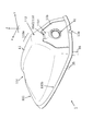
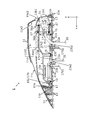
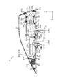
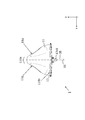
- the in-vehicle rear imaging device 1 in the first embodiment is attached to the upper surface of a vehicle 90 such as a roof, and includes a case 10, an antenna unit 30, and an imaging unit 50 (see FIGS. 1 to 11).
- the front-rear direction of the vehicle 90 to which the in-vehicle rearward imaging device 1 is attached is the x direction
- the left-right direction perpendicular to the x direction is the y direction
- the substantially vertical direction perpendicular to the x direction and the y direction is the z direction.
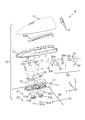
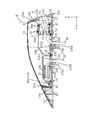
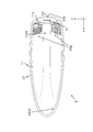
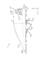
- the case 10 is a member that covers members constituting the in-vehicle rear photographing apparatus 1 such as the antenna element 31 and the camera body 51, and includes an outer case 11, an outer pad 13, and an inner case 15 (first inner case 15a and second inner case 15b). , Base 17, interior pad 19, seal member 21 (first seal member 21a, second seal member 21b), and pre-lock 23 (first pre-lock 23a, second pre-lock 23b).
- the antenna unit 30 includes an antenna element 31 and an antenna cable 35.
- the imaging unit 50 includes a camera body 51 including an imaging element such as a CMOS, a camera cable 55, a first packing 56a, a second packing 56b, a bracket 57, and a ground plate 59.
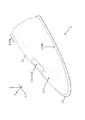
- the outer case 11 is made of a synthetic resin having a non-light-transmitting property and a radio-transmitting property (a resin molded product formed of a synthetic resin including Polycarbonate and ASA (Acrylate Styrene Acrylonitrile)).
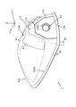
- the exterior case 11 is a member having an open bottom surface and constituting the in-vehicle rear photographing apparatus 1 and other than the exterior case 11 (the exterior pad 13, the interior case 15, the base 17, the interior pad 19, the antenna element 31, the antenna A part of the cable 35, a part of the camera body 51, a part of the camera cable 55, etc.) are covered from above in the z direction (see FIGS. 1 and 10). However, a part of the lens of the camera body 51 may protrude from the back surface of the outer case 11 to the rear side in the x direction.
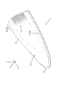
- the outer case 11 has a top portion 110a at the upper portion on the rear side in the x direction, and is a slope connecting the lower end peripheral portion 110b and the top portion 110a having a ring shape and at least the front side in the x direction having a substantially semi-elliptical shape or a substantially leaf shape.
- An outline is formed.
- the first slope 111 connecting the x-direction front portion of the lower peripheral edge 110b and the top 110a is more gradual than the second slope 112 connecting the x-direction rear portion of the lower peripheral 110b and the top 110a. It has a gentle slope.
- the shape of the exterior case 11 described above is said to be a so-called shark fin shape, for example.
- an opening for allowing light from the rear to enter the lens of the camera body 51 of the imaging unit 50 provided for photographing the back of the vehicle 90.
- a portion other than the lens in the lower back opening 11a1 is covered with a camera cover 11b.
- the camera cover 11 b covers the periphery of the lens of the camera body 51.
- the upper part of the lens of the camera body 51 in the camera cover 11b has an inclined surface (cover inclined surface 11b1) in which the front side in the x direction is higher than the rear side in the x direction.
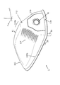
- An opening (upper back opening 11a2) is provided on the back surface (second slope 112) of the outer case 11 and above the lower back opening 11a1.
- An opening (front opening 11 c) is provided on the front surface of the outer case 11.
- 1st Embodiment demonstrates the form in which the upper part of one opening provided in the back surface of the exterior case 11 comprises the upper back surface opening 11a2, and the lower part comprises the lower back surface opening 11a1, two openings are demonstrated. The form provided may be sufficient.
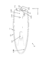
- the passage 11d that connects the upper back opening 11a2 and the front opening 11c is provided inside the exterior case 11.
- the passage 11d has a bottom surface portion 11d1 and a side surface portion 11d2, and has a substantially groove shape (or a substantially cylindrical shape) along the upper portion of the inner wall of the exterior case 11 (see FIG. 2).
- the x direction front side of the bottom surface part 11d1 is in contact with the lower end of the front opening 11c, and the x direction rear side of the bottom surface part 11d1 is in contact with the cover inclined surface 11b1 of the camera cover 11b.
- the bottom surface portion 11d1 is located on the upper side in the z direction with respect to a first inner case 15a and a second inner case 15b described later.
- the side surface portion 11d2 extends upward in the z direction from both ends of the bottom surface portion 11d1 in the y direction.
- the front side of the side part 11d2 in the x direction is in contact with the front opening 11c
- the rear side in the x direction of the side part 11d2 is in contact with the upper back opening 11a2
- the upper end of the side part 11d2 is in contact with the upper part of the inner wall of the exterior case 11.
- the inner wall on the back surface (second inclined surface 112) of the exterior case 11 and above the upper back surface opening 11a2 is such that the front side in the x direction is higher than the rear side in the x direction. It has the inclined surface 11a3 (refer FIG. 10).
- the passage 11d has a substantially cylindrical shape
- the upper surface of the end portion on the upper back opening 11a2 side of the passage 11d has an inclined surface (not shown) in which the front side in the x direction is higher than the rear side in the x direction.
- an inclined surface (an inner wall inclined surface 11a3, a cover) whose front side in the x direction is higher than the rear side in the x direction.
- An inclined surface 11b1) is provided.
- the upper part of the outer case 11, the upper back opening 11a2, the cover inclined surface 11b1, the front opening 11c, and the passage 11d form an air guide path (cavity) that penetrates the inside of the outer case 11 in the x direction, It functions as an air guiding unit that guides air that has entered through the front opening 11c to the back during traveling.
- the upper part of the interior case 15, the base 17, the interior pad 19, the antenna element 31, a part of the antenna cable 35, the camera body 51, a part of the camera cable 55, and the like is hermetically sealed by the inner wall of the exterior case 11 and the passage 11d. Covered with condition.
- the camera main body 51 is attached to the 2nd interior case 15b so that the camera cover 11b attached to the back surface opening 11a may be contacted. Since the water that has entered through the space between the camera cover 11b and the camera body 51 is discharged through the drainage notch 13a provided in the exterior pad 13, the window portion may not be provided.
- a description will be given in a form in which the window portion is not attached to a region covering the lens of the camera body 51 in the camera cover 11b.
- the lens of the camera body 51 that is provided on the forefront is the camera body that will be described later. It functions as an optical member provided on the forefront of 51 (the rear side in the x direction).
- the window portion When the window portion is attached to a region of the camera cover 11b that covers the lens of the camera body 51, the window portion functions as an optical member provided on the foremost surface (the rear side in the x direction) of the camera body 51 described later. .
- the outer case 11 is provided with a first locking claw 11e for attachment to the base 17 so as to protrude downward in the z direction from the inner wall.
- the first locking claw 11e is provided.
- the claw 11e engages with a second locking claw 17a provided on the base 17 (see FIG. 10).
- the exterior pad 13 is an annular elastic member formed of elastomer (Elastomer), rubber, or the like, and is fitted into the lower peripheral edge 110 b of the external case 11, and between the lower peripheral edge 110 b of the external case 11 and the vehicle 90.
- the gap is blindfolded and water intrusion into the outer case 11 is prevented.
- a drainage notch 13a is provided at the lower end of the exterior pad 13 at the rear end in the x direction as a discharge port for water that has entered between the exterior case 11 and the interior case 15 (FIGS. 2 and 5). FIG. 8 and FIG. 10).
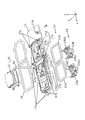
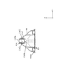
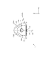
- the interior case 15 has a first interior case 15a and a second interior case 15b.
- the first interior case 15a has an open bottom surface, a region on the base 17 in the antenna cable 35 (a region between a portion connected to the antenna element 31 and a portion inserted into the first opening 17c1), and an antenna element. 31 is covered from above in the z direction.
- the first interior case 15a is made of a synthetic resin having a non-light-transmitting property and a radio wave transmitting property (a resin molded product formed of a synthetic resin including polycarbonate and ASA (Acrylate Styrene Acrylonitrile)).
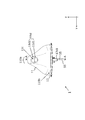
- the second interior case 15b is disposed behind the first interior case 15a in the x direction, the bottom surface and the back surface are open, and the region on the base 17 in the camera cable 55 (second portion from the portion connected to the camera body 51 is second). The region between the portion inserted into the opening 17c2 is covered from above in the z direction.
- the camera body 51 is attached to the opened portion on the back surface of the second interior case 15b via the second packing 56b, the bracket 57, and the first packing 56a.
- the first packing 56a, the second packing 56b, and the bracket 57 The space between the second interior case 15b and the camera body 51 is sealed.
- the second interior case 15b is preferably made of a metal such as aluminum. Screw holes 15c used for screwing to the base 17 are provided at the lower ends of the first inner case 15a and the second inner case 15b.
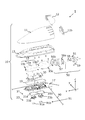
- the base 17 is a metal base such as aluminum. However, the polybutylene terephthalate (Polybutylene Terephthalate) other than the conductive region connecting the ground plate mounting portion 17e and the second boss 17d2 extending downward in the base 17 and the region including the connection region in contact with the second interior case 15b in the base 17 is used. ) Or the like.
- the base 17 has a second locking claw 17a that engages with the first locking claw 11e of the outer case 11 to lock the outer case 11 on the outer peripheral portion (see FIG. 10).
- the base 17 holds the outer case 11 with the imaging unit 50 including the camera body 51 interposed therebetween.
- the antenna element 31 including the antenna substrate is attached to the upper surface of the base 17 and covered with the first interior case 15a by screwing.
- the periphery of the base 17 is provided with a recess (screw receiver 17b) used for screwing with the interior case 15 (first interior case 15a, second interior case 15b).
- the interior pad 19 is attached to the peripheral edge of the upper surface of the base 17 and inside the screw receiver 17b.
- the base 17 is provided with a wiring opening 17c.
- the wiring opening 17c is different from the two openings (the first opening 17c1 and the first opening 17c1 provided in the region covered with the first interior case 15a in the base 17 and more than the first opening 17c1.
- the second opening 17c2) is provided on the rear side in the direction and is provided in a region of the base 17 covered with the second interior case 15b.
- the antenna cable 35 connected to the antenna element 31 extends downward in the z direction of the base 17 through the first opening 17c1 (see FIGS. 1, 3, and 10).
- the camera cable 55 connected to the camera body 51 extends downward in the z direction of the base 17 via the second opening 17c2.
- bosses 17d On the bottom surface of the base 17, there are provided bosses 17d (first boss 17d1 and second boss 17d2) extending downward in the z direction. Specifically, a first boss 17d1 extending downward in the z direction is provided on the lower surface of the base 17 in the region covered with the first interior case 15a. A second boss 17d2 extending downward in the z direction is provided on the lower surface of the base 17 in the region covered with the second interior case 15b.
- the boss 17d (the first boss 17d1 and the second boss 17d2) may be configured separately from the base 17 (see FIG. 10), or may be configured integrally (not shown). Also good.
- the form in which the boss 17d extends downward from the base 17 in the z direction has been described. However, the form in which the boss 17d is attached to the base 17 by screwing or the like from below in the z direction may be used.
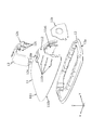
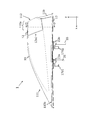
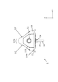
- the in-vehicle rearward imaging device 1 is fixed to the upper surface of the vehicle 90 by a pre-lock 23 (first pre-lock 23a, second pre-lock 23b), a boss 17d (first boss 17d1, second boss 17d2), a washer with a claw or a nut. This is done using mounting brackets (not shown).
- the first boss 17d1 is inserted into the first boss hole 23a1 provided in the first prelock 23a, and the antenna cable 35 passing through the first opening 17c1 is the first provided in the first prelock 23a.
- the first pre-lock 23a is the first
- the fitting hole 91a is fitted from above
- the second pre-lock 23b is provided behind the first attachment hole 91a.
- the base 17 is placed on the roof of the vehicle 90 from above, and a mounting bracket (not shown) such as a claw washer or nut is used from the lower surface of the vehicle 90 roof.
- the first boss 17d1 and the second boss 17d2 are fixed.
- FIG. 29 of the third embodiment the claw washer 24a is connected to the first prelock 23a and the second prelock 23b.
- a state where the nut 24b is attached to the first boss 17d1 and the second boss 17d2 is shown.
- first pre-lock 23a is fitted into the first mounting hole 91a provided in the roof of the vehicle 90 from above
- the second pre-lock 23b is fitted into the second mounting hole 91b from above with the roof of the vehicle 90 to provide a claw washer
- the first boss 17d1 is inserted into the first boss hole 23a1, and the antenna cable 35 passing through the first opening 17c1 is inserted into the first cable hole 23a2.
- the second boss 17d2 is inserted into the second boss hole 23b1, the camera cable 55 passing through the second opening 17c2 is inserted into the second cable hole 23b2, and the base 17 is placed on the roof of the vehicle 90.
- the first boss 17d1 and the second boss 17d2 may be fixed from the lower surface of the roof 90 using a nut (not shown) or the like.
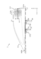
- the lower surface of the base 17 is provided with a seal member 21 (first seal member 21a, second seal member 21b) which is an annular elastic member formed of elastomer (Elastomer), rubber or the like. And the roof of the vehicle 90 and the periphery of the area where the mounting holes 91 (first mounting hole 91a and second mounting hole 91b) are provided is watertightly sealed.
- the first seal member 21a is disposed so that the ring constituting the first seal member 21a passes the first boss 17d1, the first pre-lock 23a, and the antenna cable 35.
- the second seal member 21b is arranged so that the ring constituting the second seal member 21b passes the second boss 17d2, the second pre-lock 23b, and the camera cable 55.
- the ring constituting one seal member 21 includes a first boss 17d1, a first prelock 23a, and an antenna cable. 35, the second boss 17d2, the second pre-lock 23b, and the camera cable 55 may be passed.
- an earth plate attachment portion 17 e for screwing the earth plate 59 for grounding the camera body 51 is provided on the upper surface of the base 17, in the vicinity of the area where the camera body 51 is attached.
- the interior pad 19 is an annular elastic member formed of an elastomer or rubber, and is provided on the upper surface of the base 17 (see FIGS. 1, 3, and 10).
- the interior pad 19 has an annular region facing the lower end of the first interior case 15a, and an annular region facing the lower end of the second interior case 15b.
- the pre-lock 23 is a resin member that fits into the mounting hole 91 of the vehicle 90.
- the pre-lock 23 includes two pre-locks 23 (first pre-lock 23a and second pre-lock 23b).
- the first pre-lock 23a has a first boss hole 23a1 through which the first boss 17d1 passes and a first cable hole 23a2 that faces the first opening 17c1 and passes through the antenna cable 35, and a portion protruding downward in the z direction is the first. It fits into the mounting hole 91a.
- the second pre-lock 23b has a second boss hole 23b1 through which the second boss 17d2 passes, and a second cable hole 23b2 that faces the second opening 17c2 and passes the camera cable 55, and a portion protruding downward in the z direction is the second. It fits into the mounting hole 91b.
- the boss 17d (the first boss 17d1 and the second boss 17d2) may be inserted into another mounting hole (not shown) provided in the vehicle 90 without the pre-lock 23 interposed therebetween. Further, the pre-lock 23 may be attached to the base 17 from below in the z direction as in the first embodiment, but may be attached to the base 17 from above in the z direction.
- the antenna element 31 may be configured by a planar antenna for GPS reception or the like, or may be configured by an upper element and a lower element for receiving AM / FM broadcasts. 17 or the first interior case 15a. However, when the first interior case 15a is not provided, a part of the antenna element 31 may be attached to the exterior case 11 or the passage 11d.
- the antenna cable 35 is used to supply power to an antenna amplifier included in the antenna element 31 and to output a signal obtained by the antenna element 31.
- the imaging unit 50 is arranged so that the imaging surface of the imaging element in the camera body 51 faces the rear of the vehicle 90.
- a housing for holding the circuit board and the image sensor in the camera body 51 is made of metal (for example, aluminum) that also serves as a shield conductor.
- a camera cable 55 used for supplying power and control signals to the camera main body 51 and outputting image signals obtained by the camera main body includes a first packing 56 a and a bracket 57 from the back of the camera main body 51.
- the second packing 56b, the second inner case 15b, and the second opening 17c2 extend downward in the z direction of the base 17.
- the camera cable 55 extending from the camera body 51 extends linearly in the substantially x direction perpendicular to the imaging surface of the image sensor and on the back side (substantially in the x direction front side), and on the lower side in the z direction near the upper side of the second opening 17c2. It is bent and extends downward in the z direction.
- the bracket 57 is made of metal and has a substantially cylindrical shape with an open front surface and a rear surface, and is used to adjust the mounting angle between the second interior case 15 b and the camera body 51. Specifically, the angle formed between the normal of the surface of the bracket 57 facing the camera body 51 and the base 17 is the first angle ⁇ 1 (see FIG. 10), and the angle formed is different from the first angle ⁇ 1. (Not shown) is prepared, and the bracket 57 to be used is selected in accordance with the inclination of the region where the in-vehicle rearward imaging device 1 is attached on the roof of the vehicle 90. A plurality of camera covers 11b having different shapes are prepared in accordance with the brackets 57 to be used, and the camera cover 11b corresponding to the selected bracket 57 is used.
- the housing of the camera body 51 is connected to the ground plate mounting portion 17e via a ground plate 59 made of metal for the purpose of grounding (see FIGS. 1 and 3).
- the roof of the vehicle 90 is provided with mounting holes 91 (first mounting hole 91a and second mounting hole 91b) of the in-vehicle rear photographing apparatus 1.
- the first mounting hole 91a includes a region facing the first opening 17c1
- the second mounting hole 91b includes a region facing the second opening 17c2.
- the first pre-lock 23a is fitted into the first mounting hole 91a
- the second pre-lock 23b is fitted into the second mounting hole 91b.
- two mounting holes (a first mounting hole 91a for passing the first boss 17d1 and the antenna cable 35 and a second mounting hole 91b for passing the second boss 17d2 and the camera cable 55) are provided.
- a form (refer FIG. 1) is demonstrated, the form which provides the attachment hole for letting one boss pass through may be sufficient (not shown). Further, the antenna cable 35 and the camera cable 55 may pass through one mounting hole.
- the air flowing near the side surface of the exterior case 11 is separated from the exterior case 11 near the boundary between the side surface and the back surface while the vehicle 90 is traveling, and in the vicinity of the back surface. Air is difficult to flow through.
- an optical member such as a lens
- the optical member When water droplets or dust adheres to the optical member, the water droplets or the like are moved or blown around the lens by air, and the water droplets or the like are removed from the optical member.
- the air passing through the front surface of the optical member functions as an air curtain, and water drops such as rainwater are unlikely to adhere to the front surface of the optical member. Thereby, it becomes possible to make the optical member provided in the forefront of the camera main body 51 into a state in which water droplets or the like do not adhere.
- the air passing through the passage 11d cools the metal parts such as the casing of the camera body 51 and the second interior case 15b and the bracket 57 disposed at the lower part of the passage 11d, and suppresses the temperature rise of the camera body 51. It becomes possible.
- a passage 11d penetrating in the front-rear direction (x direction) is provided above the first interior case 15a, the second interior case 15b, and the camera body 51 in the exterior case 11, and the upper portion of the exterior case 11 And the optical member provided on the foremost surface (rear side in the x direction) of the camera body 51 by the air passing through the air guide path formed by the upper rear opening 11a2, the cover inclined surface 11b1, the front opening 11c, and the passage 11d.
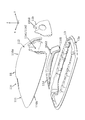
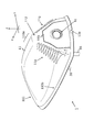
- the exterior case cover 12 is formed on the rear side of the side surface of the exterior case 11 with a gap penetrating substantially in the x direction as an air guiding portion that guides air flowing near the side surface of the exterior case 11 to the rear surface during traveling. And an air guide path is formed between the outer case cover 12 and the outer case 11 (see the second embodiment, FIGS. 12 to 22).
- the exterior case cover 12 covers the side surface of the exterior case 11 and the rear side in the x direction, and is separated from the exterior case 11 except that it is connected to the exterior case 11 at several places such as an upper end portion and a lower end portion. Between the outer case cover 12 and the outer case 11, the front side in the x direction and the rear side in the x direction are opened, and air guide paths (cavities) penetrating the front and rear in the x direction are formed (front opening 12a1, rear opening 12a2). .
- An air guide wall 12b is provided at the rear end of the exterior case cover 12 in the x direction so as not to come into contact with the side surface or the back surface of the exterior case 11 and protrudes inward substantially perpendicular to the exterior case cover 12. .
- the exterior case cover 12 may be configured separately from the exterior case 11 or may be configured integrally.
- the exterior case 11 and the exterior case cover 12 are configured separately, and a protruding portion 12 c extending downward in the z direction in the exterior case cover 12 is formed in the attachment hole 110 c provided on the side surface of the exterior case 11.
- the form in which the exterior case cover 12 is attached to the exterior case 11 by being fitted is shown (see FIGS. 13 and 21).
- a part of the air discharged from the rear opening 12a2 is guided by the air guide wall 12b on the back surface (second inclined surface 112) of the outer case 11 and downward in the z direction, and is the foremost surface (back in the x direction) of the camera body 51.
- an optical member such as a lens
- the air passing through the front surface of the optical member functions as an air curtain, and water drops such as rainwater are unlikely to adhere to the front surface of the optical member.
- the optical member provided in the forefront of the camera main body 51 into a state in which water droplets or the like do not adhere.
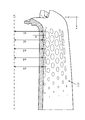
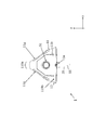
- a vortex generator (first vortex generator 11f (third embodiment)) is provided behind the side surface of the outer case 11 as an air guide unit that guides air that flows near the side surface of the outer case 11 during traveling to the back surface. 23 to 30) and a second vortex generator 11g (fourth embodiment, see FIGS. 31 to 36)) may be considered.
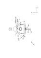
- dimple processing is performed on the rear side of the side surface of the outer case 11 (a plurality of substantially spherical crown-shaped recesses are provided).
- the substantially spherical crown-shaped recess has a radius of curvature r of 5 mm and a depth d of 0.35 mm, which is the deepest one arranged on the rear side.
- the rear one is shorter than the front one.
- a substantially spherical crown-shaped recess is arranged (a1 ⁇ a2 ⁇ a3 ⁇ a4 ⁇ a5, see FIG. 30). That is, due to the shape of the side surface of the exterior case 11, except for the substantially spherical crown-shaped recesses arranged in one or two rows on the rear side, the substantially spherical crown-shaped recesses are those on the rear side of the front side. Become deeper.
- the air flowing near the side surface of the outer case 11 passes through the recess of the first vortex generating portion 11 f provided on the rear side of the side surface of the outer case 11. 112) A turbulent flow is generated in the vicinity, and the air flowing on the side surface of the outer case 11 does not separate from the outer case 11 and the air easily flows near the back surface of the outer case 11. A part of the air flowing through the side surface of the outer case 11 is guided by the first vortex generator 11f on the back surface of the outer case 11 and downward in the z direction without being peeled off from the outer case 11, so It passes through the front surface of an optical member (such as a lens) provided on the rear side in the x direction.
- an optical member such as a lens
- the optical member When water droplets or dust adheres to the optical member, the water droplets or the like are moved or blown around the lens by air, and the water droplets or the like are removed from the optical member.
- the air passing through the front surface of the optical member functions as an air curtain, and water drops such as rainwater are unlikely to adhere to the front surface of the optical member. Thereby, it becomes possible to make the optical member provided in the forefront of the camera main body 51 into a state in which water droplets or the like do not adhere.
- a plurality of substantially V-shaped fins that protrude in the y direction and extend in the x direction are provided on the rear side of the side surface of the outer case 11 as the second vortex generating portion 11g.
- the fins having a substantially V-shaped cross section are arranged in the vertical direction along the side surface of the exterior case 11, and a groove having a substantially V-shaped cross section extending in the x direction is formed between adjacent fins.
- a portion of the fin having a substantially V-shaped cross section close to the back surface (second inclined surface 112) of the outer case 11 has a height h of about 0.75 mm, and the fin is gradually lowered toward the front side in the x direction. It is desirable to be formed.
- the air flowing near the side surface of the outer case 11 passes through the fins of the second vortex generating portion 11g provided on the rear side of the side surface of the outer case 11, so that the rear surface of the outer case 11 (second slope) 112)
- a turbulent flow is generated in the vicinity, and the air flowing on the side surface of the outer case 11 does not separate from the outer case 11 and the air easily flows near the back surface of the outer case 11.
- a part of the air flowing on the side surface of the outer case 11 is guided by the second vortex generator 11g on the back surface of the outer case 11 and downward in the z direction without being separated from the outer case 11, It passes through the front surface of an optical member (such as a lens) provided on the rear side in the x direction.
- an optical member such as a lens
- the optical member When water droplets or dust adheres to the optical member, the water droplets or the like are moved or blown around the lens by air, and the water droplets or the like are removed from the optical member.
- the air passing through the front surface of the optical member functions as an air curtain, and water drops such as rainwater are unlikely to adhere to the front surface of the optical member. Thereby, it becomes possible to make the optical member provided in the forefront of the camera main body 51 into a state in which water droplets or the like do not adhere.
- the form which combines several things may be sufficient as the air guidance part which guide
- the vortex generator (the first vortex generator 11f or the second vortex generator 11g) is used as a guide part on the back side of the side surface of the outer case 11, and the air flowing near the side surface of the outer case 11 during traveling is used.
- a form used as an air guiding portion for guiding to the back surface is conceivable.
- the air guiding portion (member) in each of the first to fourth embodiments is an air guiding path or a surface treatment that does not use a member such as a motor that requires electric power
- the antenna portion 30 is used. Water droplets attached to the optical member can be removed with a low possibility of adversely affecting the reception performance.
Landscapes
- Engineering & Computer Science (AREA)
- Physics & Mathematics (AREA)
- General Physics & Mathematics (AREA)
- Multimedia (AREA)
- Signal Processing (AREA)
- Mechanical Engineering (AREA)
- Aviation & Aerospace Engineering (AREA)
- Studio Devices (AREA)
- Camera Bodies And Camera Details Or Accessories (AREA)
- Structure And Mechanism Of Cameras (AREA)
- Cameras Adapted For Combination With Other Photographic Or Optical Apparatuses (AREA)
- Fittings On The Vehicle Exterior For Carrying Loads, And Devices For Holding Or Mounting Articles (AREA)
Applications Claiming Priority (2)
| Application Number | Priority Date | Filing Date | Title |
|---|---|---|---|
| JP2016-210294 | 2016-10-27 | ||
| JP2016210294A JP6970496B2 (ja) | 2016-10-27 | 2016-10-27 | 車載後方撮影装置 |
Publications (1)
| Publication Number | Publication Date |
|---|---|
| WO2018079199A1 true WO2018079199A1 (ja) | 2018-05-03 |
Family
ID=62023414
Family Applications (1)
| Application Number | Title | Priority Date | Filing Date |
|---|---|---|---|
| PCT/JP2017/035803 Ceased WO2018079199A1 (ja) | 2016-10-27 | 2017-10-02 | 車載後方撮影装置 |
Country Status (2)
| Country | Link |
|---|---|
| JP (1) | JP6970496B2 (enExample) |
| WO (1) | WO2018079199A1 (enExample) |
Cited By (5)
| Publication number | Priority date | Publication date | Assignee | Title |
|---|---|---|---|---|
| WO2018199108A1 (ja) * | 2017-04-25 | 2018-11-01 | 株式会社ヨコオ | アンテナ装置、及び車両 |
| WO2019163267A1 (ja) * | 2018-02-26 | 2019-08-29 | 株式会社デンソー | 車両用アンテナ装置 |
| CN110861584A (zh) * | 2018-08-28 | 2020-03-06 | 本田技研工业株式会社 | 车辆用摄像单元 |
| WO2022067314A1 (en) * | 2020-09-24 | 2022-03-31 | American University Of Sharjah | Fin device with camera |
| US12341240B2 (en) | 2019-10-17 | 2025-06-24 | Harada Industry Co., Ltd. | Vehicle exterior device |
Families Citing this family (4)
| Publication number | Priority date | Publication date | Assignee | Title |
|---|---|---|---|---|
| US11247616B2 (en) | 2019-07-25 | 2022-02-15 | Ford Global Technologies, Llc | Sensor airflow apparatus |
| CN111660949B (zh) * | 2020-05-18 | 2021-11-19 | 宿州青智网络科技有限公司 | 一种车辆行驶图像识别方法 |
| DE102022103830A1 (de) * | 2022-02-17 | 2023-08-17 | Webasto SE | Dachmodul mit einer Sende- und/oder Empfangseinrichtung |
| KR102722438B1 (ko) * | 2022-03-30 | 2024-10-29 | 포티투닷 주식회사 | 차량용 센서 장치 |
Citations (21)
| Publication number | Priority date | Publication date | Assignee | Title |
|---|---|---|---|---|
| JPH0572620U (ja) * | 1992-03-13 | 1993-10-05 | 日産ディーゼル工業株式会社 | 自動車のバックミラーの構造 |
| JPH10114258A (ja) * | 1996-10-11 | 1998-05-06 | Toyota Autom Loom Works Ltd | 自動車用装飾具及びリヤコンビネーションランプ |
| JPH10181642A (ja) * | 1996-12-27 | 1998-07-07 | Kanto Auto Works Ltd | 自動車のルーフスポイラ |
| JP2004299511A (ja) * | 2003-03-31 | 2004-10-28 | Clarion Co Ltd | 車両後方確認装置 |
| JP2005014858A (ja) * | 2003-06-30 | 2005-01-20 | Nissan Motor Co Ltd | カメラ内蔵ドアミラー |
| JP2009135741A (ja) * | 2007-11-30 | 2009-06-18 | Nippon Antenna Co Ltd | アンテナ装置 |
| JP2009248661A (ja) * | 2008-04-03 | 2009-10-29 | Nippon Soken Inc | ウォッシャノズル付カメラおよびウォッシャノズル |
| JP2009286216A (ja) * | 2008-05-28 | 2009-12-10 | Denso Corp | 風圧発生装置 |
| JP2010163103A (ja) * | 2009-01-16 | 2010-07-29 | Denso Corp | 駐車支援装置および駐車支援システム |
| JP2013065401A (ja) * | 2011-09-15 | 2013-04-11 | Sakae Riken Kogyo Co Ltd | 車両用ドアミラー並びに車両用ドアミラーにおける灯具及びレンズカバー |
| JP2014150496A (ja) * | 2013-02-04 | 2014-08-21 | Toyota Auto Body Co Ltd | 車両用カメラ装置 |
| US20140292593A1 (en) * | 2011-12-14 | 2014-10-02 | Laird Technologies, Inc. | Multiband mimo antenna assemblies operable with lte frequencies |
| JP2015154104A (ja) * | 2014-02-10 | 2015-08-24 | 株式会社ヨコオ | アンテナ装置 |
| JP2016010098A (ja) * | 2014-06-26 | 2016-01-18 | 原田工業株式会社 | アンテナユニット |
| JP2016018203A (ja) * | 2014-07-11 | 2016-02-01 | 株式会社東海理化電機製作所 | 撮像装置 |
| WO2016125405A1 (ja) * | 2015-02-02 | 2016-08-11 | 本田技研工業株式会社 | 車両用サイドミラー装置 |
| WO2017046972A1 (ja) * | 2015-09-14 | 2017-03-23 | 株式会社ヨコオ | 車載アンテナ装置 |
| WO2017046971A1 (ja) * | 2015-09-14 | 2017-03-23 | 株式会社ヨコオ | アンテナ装置 |
| US20170136959A1 (en) * | 2015-11-12 | 2017-05-18 | Connaught Electronics Ltd. | Sharkfin rf and camera integration |
| WO2017102346A1 (en) * | 2015-12-16 | 2017-06-22 | Connaught Electronics Ltd. | Antenna arrangement for a motor vehicle with an antenna and a shielding device for electromagnetically shielding an electronic unit as well as motor vehicle |
| WO2017125477A1 (en) * | 2016-01-21 | 2017-07-27 | Connaught Electronics Ltd. | Antenna module for a motor vehicle, driver assistance system as well as motor vehicle |
-
2016
- 2016-10-27 JP JP2016210294A patent/JP6970496B2/ja not_active Expired - Fee Related
-
2017
- 2017-10-02 WO PCT/JP2017/035803 patent/WO2018079199A1/ja not_active Ceased
Patent Citations (21)
| Publication number | Priority date | Publication date | Assignee | Title |
|---|---|---|---|---|
| JPH0572620U (ja) * | 1992-03-13 | 1993-10-05 | 日産ディーゼル工業株式会社 | 自動車のバックミラーの構造 |
| JPH10114258A (ja) * | 1996-10-11 | 1998-05-06 | Toyota Autom Loom Works Ltd | 自動車用装飾具及びリヤコンビネーションランプ |
| JPH10181642A (ja) * | 1996-12-27 | 1998-07-07 | Kanto Auto Works Ltd | 自動車のルーフスポイラ |
| JP2004299511A (ja) * | 2003-03-31 | 2004-10-28 | Clarion Co Ltd | 車両後方確認装置 |
| JP2005014858A (ja) * | 2003-06-30 | 2005-01-20 | Nissan Motor Co Ltd | カメラ内蔵ドアミラー |
| JP2009135741A (ja) * | 2007-11-30 | 2009-06-18 | Nippon Antenna Co Ltd | アンテナ装置 |
| JP2009248661A (ja) * | 2008-04-03 | 2009-10-29 | Nippon Soken Inc | ウォッシャノズル付カメラおよびウォッシャノズル |
| JP2009286216A (ja) * | 2008-05-28 | 2009-12-10 | Denso Corp | 風圧発生装置 |
| JP2010163103A (ja) * | 2009-01-16 | 2010-07-29 | Denso Corp | 駐車支援装置および駐車支援システム |
| JP2013065401A (ja) * | 2011-09-15 | 2013-04-11 | Sakae Riken Kogyo Co Ltd | 車両用ドアミラー並びに車両用ドアミラーにおける灯具及びレンズカバー |
| US20140292593A1 (en) * | 2011-12-14 | 2014-10-02 | Laird Technologies, Inc. | Multiband mimo antenna assemblies operable with lte frequencies |
| JP2014150496A (ja) * | 2013-02-04 | 2014-08-21 | Toyota Auto Body Co Ltd | 車両用カメラ装置 |
| JP2015154104A (ja) * | 2014-02-10 | 2015-08-24 | 株式会社ヨコオ | アンテナ装置 |
| JP2016010098A (ja) * | 2014-06-26 | 2016-01-18 | 原田工業株式会社 | アンテナユニット |
| JP2016018203A (ja) * | 2014-07-11 | 2016-02-01 | 株式会社東海理化電機製作所 | 撮像装置 |
| WO2016125405A1 (ja) * | 2015-02-02 | 2016-08-11 | 本田技研工業株式会社 | 車両用サイドミラー装置 |
| WO2017046972A1 (ja) * | 2015-09-14 | 2017-03-23 | 株式会社ヨコオ | 車載アンテナ装置 |
| WO2017046971A1 (ja) * | 2015-09-14 | 2017-03-23 | 株式会社ヨコオ | アンテナ装置 |
| US20170136959A1 (en) * | 2015-11-12 | 2017-05-18 | Connaught Electronics Ltd. | Sharkfin rf and camera integration |
| WO2017102346A1 (en) * | 2015-12-16 | 2017-06-22 | Connaught Electronics Ltd. | Antenna arrangement for a motor vehicle with an antenna and a shielding device for electromagnetically shielding an electronic unit as well as motor vehicle |
| WO2017125477A1 (en) * | 2016-01-21 | 2017-07-27 | Connaught Electronics Ltd. | Antenna module for a motor vehicle, driver assistance system as well as motor vehicle |
Cited By (7)
| Publication number | Priority date | Publication date | Assignee | Title |
|---|---|---|---|---|
| WO2018199108A1 (ja) * | 2017-04-25 | 2018-11-01 | 株式会社ヨコオ | アンテナ装置、及び車両 |
| JPWO2018199108A1 (ja) * | 2017-04-25 | 2020-03-12 | 株式会社ヨコオ | アンテナ装置、及び車両 |
| JP7083817B2 (ja) | 2017-04-25 | 2022-06-13 | 株式会社ヨコオ | アンテナ装置、及び車両 |
| WO2019163267A1 (ja) * | 2018-02-26 | 2019-08-29 | 株式会社デンソー | 車両用アンテナ装置 |
| CN110861584A (zh) * | 2018-08-28 | 2020-03-06 | 本田技研工业株式会社 | 车辆用摄像单元 |
| US12341240B2 (en) | 2019-10-17 | 2025-06-24 | Harada Industry Co., Ltd. | Vehicle exterior device |
| WO2022067314A1 (en) * | 2020-09-24 | 2022-03-31 | American University Of Sharjah | Fin device with camera |
Also Published As
| Publication number | Publication date |
|---|---|
| JP6970496B2 (ja) | 2021-11-24 |
| JP2018069874A (ja) | 2018-05-10 |
Similar Documents
| Publication | Publication Date | Title |
|---|---|---|
| JP6970496B2 (ja) | 車載後方撮影装置 | |
| JP7003048B2 (ja) | 車載アンテナ装置、及びアンテナシステム | |
| CN110171487B (zh) | 传感器的安装构造 | |
| CN111629290A (zh) | 附接到车辆的外部部分的麦克风设备 | |
| JP2018074371A (ja) | 車載用アンテナ装置 | |
| KR102566959B1 (ko) | 레이더 장치 | |
| JP7227231B2 (ja) | 車載用アンテナ装置 | |
| US10618475B2 (en) | Imaging apparatus | |
| CN109216971B (zh) | 电力转换装置以及电力转换装置在车辆上的安装结构 | |
| CN111034165B (zh) | 车辆相机 | |
| JP6594717B2 (ja) | 防水構造 | |
| JP2013216290A (ja) | ハイマウントストップランプ | |
| US12261353B2 (en) | Device for vehicle | |
| JP2017207550A (ja) | 撮像装置 | |
| JP3972487B2 (ja) | 自動車のホーン取付構造 | |
| JP2020179776A (ja) | 車両接近報知音発生装置 | |
| JP5865284B2 (ja) | 電子制御ユニット | |
| CN112009366B (zh) | 车辆用摄像单元 | |
| JP7084917B2 (ja) | アンテナ装置 | |
| KR101784630B1 (ko) | 카메라 | |
| JP3166438U (ja) | 露出式自動車用カメラの防水構造 | |
| JP4089660B2 (ja) | 防犯検知装置 | |
| JP2018037917A (ja) | スピーカボックスとこれを搭載した移動体装置 | |
| JP2022039566A (ja) | カバーおよび筐体 | |
| WO2022168395A1 (ja) | 物体検知装置 |
Legal Events
| Date | Code | Title | Description |
|---|---|---|---|
| 121 | Ep: the epo has been informed by wipo that ep was designated in this application |
Ref document number: 17864967 Country of ref document: EP Kind code of ref document: A1 |
|
| NENP | Non-entry into the national phase |
Ref country code: DE |
|
| 122 | Ep: pct application non-entry in european phase |
Ref document number: 17864967 Country of ref document: EP Kind code of ref document: A1 |