WO2018074288A1 - 車両認識装置及び車両認識方法 - Google Patents
車両認識装置及び車両認識方法 Download PDFInfo
- Publication number
- WO2018074288A1 WO2018074288A1 PCT/JP2017/036716 JP2017036716W WO2018074288A1 WO 2018074288 A1 WO2018074288 A1 WO 2018074288A1 JP 2017036716 W JP2017036716 W JP 2017036716W WO 2018074288 A1 WO2018074288 A1 WO 2018074288A1
- Authority
- WO
- WIPO (PCT)
- Prior art keywords
- lane
- vehicle
- line
- lane line
- inter
- Prior art date
- Legal status (The legal status is an assumption and is not a legal conclusion. Google has not performed a legal analysis and makes no representation as to the accuracy of the status listed.)
- Ceased
Links
Images

Classifications
-
- G—PHYSICS
- G08—SIGNALLING
- G08G—TRAFFIC CONTROL SYSTEMS
- G08G1/00—Traffic control systems for road vehicles
- G08G1/16—Anti-collision systems
- G08G1/167—Driving aids for lane monitoring, lane changing, e.g. blind spot detection
-
- B—PERFORMING OPERATIONS; TRANSPORTING
- B60—VEHICLES IN GENERAL
- B60R—VEHICLES, VEHICLE FITTINGS, OR VEHICLE PARTS, NOT OTHERWISE PROVIDED FOR
- B60R21/00—Arrangements or fittings on vehicles for protecting or preventing injuries to occupants or pedestrians in case of accidents or other traffic risks
-
- B—PERFORMING OPERATIONS; TRANSPORTING
- B60—VEHICLES IN GENERAL
- B60W—CONJOINT CONTROL OF VEHICLE SUB-UNITS OF DIFFERENT TYPE OR DIFFERENT FUNCTION; CONTROL SYSTEMS SPECIALLY ADAPTED FOR HYBRID VEHICLES; ROAD VEHICLE DRIVE CONTROL SYSTEMS FOR PURPOSES NOT RELATED TO THE CONTROL OF A PARTICULAR SUB-UNIT
- B60W30/00—Purposes of road vehicle drive control systems not related to the control of a particular sub-unit, e.g. of systems using conjoint control of vehicle sub-units
- B60W30/14—Adaptive cruise control
- B60W30/16—Control of distance between vehicles, e.g. keeping a distance to preceding vehicle
-
- B—PERFORMING OPERATIONS; TRANSPORTING
- B60—VEHICLES IN GENERAL
- B60W—CONJOINT CONTROL OF VEHICLE SUB-UNITS OF DIFFERENT TYPE OR DIFFERENT FUNCTION; CONTROL SYSTEMS SPECIALLY ADAPTED FOR HYBRID VEHICLES; ROAD VEHICLE DRIVE CONTROL SYSTEMS FOR PURPOSES NOT RELATED TO THE CONTROL OF A PARTICULAR SUB-UNIT
- B60W40/00—Estimation or calculation of non-directly measurable driving parameters for road vehicle drive control systems not related to the control of a particular sub unit, e.g. by using mathematical models
- B60W40/02—Estimation or calculation of non-directly measurable driving parameters for road vehicle drive control systems not related to the control of a particular sub unit, e.g. by using mathematical models related to ambient conditions
- B60W40/04—Traffic conditions
-
- B—PERFORMING OPERATIONS; TRANSPORTING
- B60—VEHICLES IN GENERAL
- B60W—CONJOINT CONTROL OF VEHICLE SUB-UNITS OF DIFFERENT TYPE OR DIFFERENT FUNCTION; CONTROL SYSTEMS SPECIALLY ADAPTED FOR HYBRID VEHICLES; ROAD VEHICLE DRIVE CONTROL SYSTEMS FOR PURPOSES NOT RELATED TO THE CONTROL OF A PARTICULAR SUB-UNIT
- B60W40/00—Estimation or calculation of non-directly measurable driving parameters for road vehicle drive control systems not related to the control of a particular sub unit, e.g. by using mathematical models
- B60W40/02—Estimation or calculation of non-directly measurable driving parameters for road vehicle drive control systems not related to the control of a particular sub unit, e.g. by using mathematical models related to ambient conditions
- B60W40/06—Road conditions
-
- B—PERFORMING OPERATIONS; TRANSPORTING
- B60—VEHICLES IN GENERAL
- B60W—CONJOINT CONTROL OF VEHICLE SUB-UNITS OF DIFFERENT TYPE OR DIFFERENT FUNCTION; CONTROL SYSTEMS SPECIALLY ADAPTED FOR HYBRID VEHICLES; ROAD VEHICLE DRIVE CONTROL SYSTEMS FOR PURPOSES NOT RELATED TO THE CONTROL OF A PARTICULAR SUB-UNIT
- B60W40/00—Estimation or calculation of non-directly measurable driving parameters for road vehicle drive control systems not related to the control of a particular sub unit, e.g. by using mathematical models
- B60W40/10—Estimation or calculation of non-directly measurable driving parameters for road vehicle drive control systems not related to the control of a particular sub unit, e.g. by using mathematical models related to vehicle motion
-
- G—PHYSICS
- G05—CONTROLLING; REGULATING
- G05D—SYSTEMS FOR CONTROLLING OR REGULATING NON-ELECTRIC VARIABLES
- G05D1/00—Control of position, course, altitude or attitude of land, water, air or space vehicles, e.g. using automatic pilots
- G05D1/02—Control of position or course in two dimensions
- G05D1/021—Control of position or course in two dimensions specially adapted to land vehicles
- G05D1/0231—Control of position or course in two dimensions specially adapted to land vehicles using optical position detecting means
- G05D1/0246—Control of position or course in two dimensions specially adapted to land vehicles using optical position detecting means using a video camera in combination with image processing means
-
- G—PHYSICS
- G06—COMPUTING OR CALCULATING; COUNTING
- G06T—IMAGE DATA PROCESSING OR GENERATION, IN GENERAL
- G06T1/00—General purpose image data processing
-
- G—PHYSICS
- G06—COMPUTING OR CALCULATING; COUNTING
- G06T—IMAGE DATA PROCESSING OR GENERATION, IN GENERAL
- G06T7/00—Image analysis
-
- G—PHYSICS
- G06—COMPUTING OR CALCULATING; COUNTING
- G06T—IMAGE DATA PROCESSING OR GENERATION, IN GENERAL
- G06T7/00—Image analysis
- G06T7/20—Analysis of motion
-
- G—PHYSICS
- G06—COMPUTING OR CALCULATING; COUNTING
- G06T—IMAGE DATA PROCESSING OR GENERATION, IN GENERAL
- G06T7/00—Image analysis
- G06T7/60—Analysis of geometric attributes
-
- G—PHYSICS
- G06—COMPUTING OR CALCULATING; COUNTING
- G06T—IMAGE DATA PROCESSING OR GENERATION, IN GENERAL
- G06T7/00—Image analysis
- G06T7/70—Determining position or orientation of objects or cameras
-
- G—PHYSICS
- G06—COMPUTING OR CALCULATING; COUNTING
- G06T—IMAGE DATA PROCESSING OR GENERATION, IN GENERAL
- G06T7/00—Image analysis
- G06T7/70—Determining position or orientation of objects or cameras
- G06T7/73—Determining position or orientation of objects or cameras using feature-based methods
-
- G—PHYSICS
- G06—COMPUTING OR CALCULATING; COUNTING
- G06V—IMAGE OR VIDEO RECOGNITION OR UNDERSTANDING
- G06V10/00—Arrangements for image or video recognition or understanding
- G06V10/40—Extraction of image or video features
- G06V10/48—Extraction of image or video features by mapping characteristic values of the pattern into a parameter space, e.g. Hough transformation
-
- G—PHYSICS
- G06—COMPUTING OR CALCULATING; COUNTING
- G06V—IMAGE OR VIDEO RECOGNITION OR UNDERSTANDING
- G06V20/00—Scenes; Scene-specific elements
- G06V20/50—Context or environment of the image
- G06V20/56—Context or environment of the image exterior to a vehicle by using sensors mounted on the vehicle
- G06V20/58—Recognition of moving objects or obstacles, e.g. vehicles or pedestrians; Recognition of traffic objects, e.g. traffic signs, traffic lights or roads
-
- G—PHYSICS
- G06—COMPUTING OR CALCULATING; COUNTING
- G06V—IMAGE OR VIDEO RECOGNITION OR UNDERSTANDING
- G06V20/00—Scenes; Scene-specific elements
- G06V20/50—Context or environment of the image
- G06V20/56—Context or environment of the image exterior to a vehicle by using sensors mounted on the vehicle
- G06V20/588—Recognition of the road, e.g. of lane markings; Recognition of the vehicle driving pattern in relation to the road
-
- G—PHYSICS
- G08—SIGNALLING
- G08G—TRAFFIC CONTROL SYSTEMS
- G08G1/00—Traffic control systems for road vehicles
- G08G1/16—Anti-collision systems
-
- G—PHYSICS
- G08—SIGNALLING
- G08G—TRAFFIC CONTROL SYSTEMS
- G08G1/00—Traffic control systems for road vehicles
- G08G1/16—Anti-collision systems
- G08G1/166—Anti-collision systems for active traffic, e.g. moving vehicles, pedestrians, bikes
-
- B—PERFORMING OPERATIONS; TRANSPORTING
- B60—VEHICLES IN GENERAL
- B60W—CONJOINT CONTROL OF VEHICLE SUB-UNITS OF DIFFERENT TYPE OR DIFFERENT FUNCTION; CONTROL SYSTEMS SPECIALLY ADAPTED FOR HYBRID VEHICLES; ROAD VEHICLE DRIVE CONTROL SYSTEMS FOR PURPOSES NOT RELATED TO THE CONTROL OF A PARTICULAR SUB-UNIT
- B60W2420/00—Indexing codes relating to the type of sensors based on the principle of their operation
- B60W2420/40—Photo, light or radio wave sensitive means, e.g. infrared sensors
- B60W2420/403—Image sensing, e.g. optical camera
-
- B—PERFORMING OPERATIONS; TRANSPORTING
- B60—VEHICLES IN GENERAL
- B60W—CONJOINT CONTROL OF VEHICLE SUB-UNITS OF DIFFERENT TYPE OR DIFFERENT FUNCTION; CONTROL SYSTEMS SPECIALLY ADAPTED FOR HYBRID VEHICLES; ROAD VEHICLE DRIVE CONTROL SYSTEMS FOR PURPOSES NOT RELATED TO THE CONTROL OF A PARTICULAR SUB-UNIT
- B60W2420/00—Indexing codes relating to the type of sensors based on the principle of their operation
- B60W2420/40—Photo, light or radio wave sensitive means, e.g. infrared sensors
- B60W2420/408—Radar; Laser, e.g. lidar
-
- B—PERFORMING OPERATIONS; TRANSPORTING
- B60—VEHICLES IN GENERAL
- B60W—CONJOINT CONTROL OF VEHICLE SUB-UNITS OF DIFFERENT TYPE OR DIFFERENT FUNCTION; CONTROL SYSTEMS SPECIALLY ADAPTED FOR HYBRID VEHICLES; ROAD VEHICLE DRIVE CONTROL SYSTEMS FOR PURPOSES NOT RELATED TO THE CONTROL OF A PARTICULAR SUB-UNIT
- B60W2552/00—Input parameters relating to infrastructure
- B60W2552/53—Road markings, e.g. lane marker or crosswalk
-
- B—PERFORMING OPERATIONS; TRANSPORTING
- B60—VEHICLES IN GENERAL
- B60W—CONJOINT CONTROL OF VEHICLE SUB-UNITS OF DIFFERENT TYPE OR DIFFERENT FUNCTION; CONTROL SYSTEMS SPECIALLY ADAPTED FOR HYBRID VEHICLES; ROAD VEHICLE DRIVE CONTROL SYSTEMS FOR PURPOSES NOT RELATED TO THE CONTROL OF A PARTICULAR SUB-UNIT
- B60W2554/00—Input parameters relating to objects
- B60W2554/40—Dynamic objects, e.g. animals, windblown objects
- B60W2554/404—Characteristics
- B60W2554/4045—Intention, e.g. lane change or imminent movement
-
- B—PERFORMING OPERATIONS; TRANSPORTING
- B60—VEHICLES IN GENERAL
- B60W—CONJOINT CONTROL OF VEHICLE SUB-UNITS OF DIFFERENT TYPE OR DIFFERENT FUNCTION; CONTROL SYSTEMS SPECIALLY ADAPTED FOR HYBRID VEHICLES; ROAD VEHICLE DRIVE CONTROL SYSTEMS FOR PURPOSES NOT RELATED TO THE CONTROL OF A PARTICULAR SUB-UNIT
- B60W2554/00—Input parameters relating to objects
- B60W2554/80—Spatial relation or speed relative to objects
- B60W2554/802—Longitudinal distance
-
- B—PERFORMING OPERATIONS; TRANSPORTING
- B60—VEHICLES IN GENERAL
- B60W—CONJOINT CONTROL OF VEHICLE SUB-UNITS OF DIFFERENT TYPE OR DIFFERENT FUNCTION; CONTROL SYSTEMS SPECIALLY ADAPTED FOR HYBRID VEHICLES; ROAD VEHICLE DRIVE CONTROL SYSTEMS FOR PURPOSES NOT RELATED TO THE CONTROL OF A PARTICULAR SUB-UNIT
- B60W2554/00—Input parameters relating to objects
- B60W2554/80—Spatial relation or speed relative to objects
- B60W2554/804—Relative longitudinal speed
-
- B—PERFORMING OPERATIONS; TRANSPORTING
- B60—VEHICLES IN GENERAL
- B60W—CONJOINT CONTROL OF VEHICLE SUB-UNITS OF DIFFERENT TYPE OR DIFFERENT FUNCTION; CONTROL SYSTEMS SPECIALLY ADAPTED FOR HYBRID VEHICLES; ROAD VEHICLE DRIVE CONTROL SYSTEMS FOR PURPOSES NOT RELATED TO THE CONTROL OF A PARTICULAR SUB-UNIT
- B60W2554/00—Input parameters relating to objects
- B60W2554/80—Spatial relation or speed relative to objects
- B60W2554/805—Azimuth angle
-
- B—PERFORMING OPERATIONS; TRANSPORTING
- B60—VEHICLES IN GENERAL
- B60W—CONJOINT CONTROL OF VEHICLE SUB-UNITS OF DIFFERENT TYPE OR DIFFERENT FUNCTION; CONTROL SYSTEMS SPECIALLY ADAPTED FOR HYBRID VEHICLES; ROAD VEHICLE DRIVE CONTROL SYSTEMS FOR PURPOSES NOT RELATED TO THE CONTROL OF A PARTICULAR SUB-UNIT
- B60W40/00—Estimation or calculation of non-directly measurable driving parameters for road vehicle drive control systems not related to the control of a particular sub unit, e.g. by using mathematical models
- B60W40/02—Estimation or calculation of non-directly measurable driving parameters for road vehicle drive control systems not related to the control of a particular sub unit, e.g. by using mathematical models related to ambient conditions
-
- G—PHYSICS
- G06—COMPUTING OR CALCULATING; COUNTING
- G06T—IMAGE DATA PROCESSING OR GENERATION, IN GENERAL
- G06T2207/00—Indexing scheme for image analysis or image enhancement
- G06T2207/20—Special algorithmic details
- G06T2207/20048—Transform domain processing
- G06T2207/20061—Hough transform
-
- G—PHYSICS
- G06—COMPUTING OR CALCULATING; COUNTING
- G06T—IMAGE DATA PROCESSING OR GENERATION, IN GENERAL
- G06T2207/00—Indexing scheme for image analysis or image enhancement
- G06T2207/30—Subject of image; Context of image processing
- G06T2207/30236—Traffic on road, railway or crossing
-
- G—PHYSICS
- G06—COMPUTING OR CALCULATING; COUNTING
- G06T—IMAGE DATA PROCESSING OR GENERATION, IN GENERAL
- G06T2207/00—Indexing scheme for image analysis or image enhancement
- G06T2207/30—Subject of image; Context of image processing
- G06T2207/30241—Trajectory
-
- G—PHYSICS
- G06—COMPUTING OR CALCULATING; COUNTING
- G06T—IMAGE DATA PROCESSING OR GENERATION, IN GENERAL
- G06T2207/00—Indexing scheme for image analysis or image enhancement
- G06T2207/30—Subject of image; Context of image processing
- G06T2207/30248—Vehicle exterior or interior
- G06T2207/30252—Vehicle exterior; Vicinity of vehicle
- G06T2207/30256—Lane; Road marking
-
- G—PHYSICS
- G06—COMPUTING OR CALCULATING; COUNTING
- G06T—IMAGE DATA PROCESSING OR GENERATION, IN GENERAL
- G06T2207/00—Indexing scheme for image analysis or image enhancement
- G06T2207/30—Subject of image; Context of image processing
- G06T2207/30248—Vehicle exterior or interior
- G06T2207/30252—Vehicle exterior; Vicinity of vehicle
- G06T2207/30261—Obstacle
-
- G—PHYSICS
- G06—COMPUTING OR CALCULATING; COUNTING
- G06V—IMAGE OR VIDEO RECOGNITION OR UNDERSTANDING
- G06V2201/00—Indexing scheme relating to image or video recognition or understanding
- G06V2201/08—Detecting or categorising vehicles
Definitions
- This disclosure relates to a vehicle recognition device and a vehicle recognition method for recognizing that a vehicle moves between its own lane and another lane.
- Patent Document 1 there is a vehicle recognition device that can recognize the interruption when estimating the trend of a preceding vehicle and interrupting the own lane.
- This vehicle recognition device detects the inclination angle of the adjacent preceding vehicle in the traveling direction with respect to the boundary line (division line), and determines in advance whether the preceding vehicle is about to interrupt the own lane based on the magnitude of the inclination angle. Deciding.
- the boundary line that divides the own lane in which the host vehicle is traveling and the other lane in which the other vehicle is traveling is not always properly detected.
- the boundary line is faint and interrupted, or that an in-vehicle camera provided in the host vehicle is hindered by an adjacent vehicle, and the boundary line may not be detected properly.
- the vehicle recognition device described in Patent Document 1 cannot specify the inclination of the traveling direction with respect to the boundary line, and determines the interruption. I can't do it.
- the present disclosure has been made in view of the above circumstances, and recognizes that the vehicle moves between the own lane and the other lane even when the lane marking that divides the own lane and the other lane cannot be detected properly. It is a main object of the present invention to provide a vehicle recognition device and a vehicle recognition method that can be performed.
- This disclosure is as follows in order to solve the above problems.
- An acquisition unit that acquires image information based on an image captured by an in-vehicle camera, a lane line detection unit that detects lane lines on both the left and right sides that divide a lane in which the vehicle travels based on the image information, A vehicle detection unit for detecting position information; and a recognition unit for recognizing movement of the other vehicle between lanes between the own lane and the other lane on which the host vehicle travels, the recognition unit detecting the lane marking A second lane line different from the first lane line that divides the own lane and the other lane, and a lane width between the first lane line and the second lane line The inter-lane movement is recognized based on the position information of the other vehicle.
- the recognition unit travels based on the second lane line different from the first lane line, the lane width between the first lane line and the second lane line, and the position information of the other vehicle. Recognize that other vehicles move between the own lane and other lanes. For this reason, even if it is a case where the 1st lane marking which divides the own lane and other lanes is not detected appropriately, it can recognize that other vehicles move.
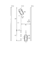
- FIG. 1 is a block diagram showing a schematic configuration of a vehicle control device
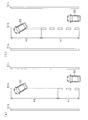
- FIG. 2 is a schematic diagram showing the departure of the vehicle
- FIGS. 3A and 3B are schematic diagrams showing the difference between the non-detection parts
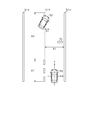
- FIG. 4 is a schematic diagram showing the interruption of the vehicle.
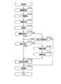
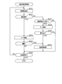
- FIG. 5 is a flowchart showing the follow-up process.
- FIG. 6 is a flowchart showing the tracking target changing process.
- the vehicle control device that controls the vehicle is mounted on the vehicle.
- the vehicle control device has an ACC (Adaptive Cruise Control) function, and causes the host vehicle to follow the vehicle so that the detected distance to the other vehicle becomes a target value of the inter-vehicle distance according to the vehicle speed.
- ACC Adaptive Cruise Control
- the inter-vehicle distance device includes a radar device 11, an image acquisition device 12, an inter-vehicle control ECU 13, an engine ECU 14, and a brake ECU 15.
- the inter-vehicle control ECU 13 functions as a vehicle recognition device using information obtained from the radar device 11 and the image acquisition device 12, and performs inter-vehicle distance control (vehicle following control) in cooperation with the engine ECU 14 and the brake ECU 15. .
- the inter-vehicle control ECU 13 is connected to the radar device 11 and the image acquisition device 12 through a vehicle-mounted network so as to communicate with each other.
- the inter-vehicle control ECU 13 is connected to the engine ECU 14 and the brake ECU 15 so as to communicate with each other via an in-vehicle network.
- the inter-vehicle control ECU 13 is connected to the ACC switch 16 via a dedicated line such as serial communication.
- the engine ECU 14 is connected to the transmission 17, the throttle motor 18, and the throttle sensor 19 through dedicated lines such as serial communication.
- the brake ECU 15 is connected to the brake ACT (actuator) 20 via a dedicated line such as serial communication.
- the radar device 11, the image acquisition device 12, and the ECUs 13 to 15 are information processing devices equipped with a microcomputer, a wire harness interface, and the like.
- the microcomputer includes a CPU, a ROM, a RAM, an I / O, a CAN communication device, and the like.
- the radar device 11 is a device that detects an inter-vehicle distance, a relative speed, an azimuth, and a relative position with another vehicle (a vehicle other than the host vehicle) for each vehicle, and transmits the detected information to the inter-vehicle control ECU 13 as radar information. More specifically, the radar apparatus 11 is a radar apparatus that uses, for example, a millimeter wave band high-frequency signal as a transmission wave. The radar apparatus 11 detects a position of an object within the detection range by setting a region within a predetermined detection angle in front of the host vehicle as a detection range.
- the radar device 11 transmits a search wave and receives a reflected wave by a plurality of antennas, a distance calculation unit 11b that calculates an inter-vehicle distance from another vehicle (object), and another vehicle.
- Various functions are executed by a relative speed calculation unit 11c that calculates a relative speed with respect to the (object) and an azimuth calculation unit 11d that calculates the direction of the other vehicle (object) with respect to the host vehicle.
- the distance calculation unit 11b calculates an inter-vehicle distance from another vehicle based on the transmission time of the exploration wave and the reception time of the reflected wave.
- the relative speed calculation unit 11c calculates the relative speed based on the frequency of the reflected wave reflected by the other vehicle that has changed due to the Doppler effect.
- the direction calculation unit 11d calculates the direction of the other vehicle based on the phase difference of the reflected waves received by the plurality of antennas.
- the radar apparatus 11 calculates radar information (vehicle distance, relative speed, direction, and relative position) at predetermined intervals, and transmits the calculated radar information to the vehicle control ECU 13.
- the image acquisition device 12 is a device that captures the surroundings of the host vehicle and transmits the captured image to the inter-vehicle control ECU 13 as image information. More specifically, the image acquisition device 12 is a monocular vehicle-mounted camera, such as a CCD camera or a CMOS image sensor. The image acquisition device 12 is attached to a predetermined height in the center in the vehicle width direction of the vehicle, and images an area that extends in a predetermined angle range toward the front of the vehicle from an overhead viewpoint. The captured image is transmitted as image information to the inter-vehicle control ECU 13. In addition, although it was set as the monocular vehicle-mounted camera, a several camera (compound eye camera) may be sufficient.
- the inter-vehicle control ECU 13 is connected to the ACC switch 16.
- the ACC switch 16 When the ACC switch 16 is operated, ON / OFF of the ACC function is instructed to the inter-vehicle control ECU 13.
- the inter-vehicle control ECU 13 executes a follow-up process that will be described later. By executing the follow-up process, the inter-vehicle control ECU 13 determines the acceleration instruction value of the own vehicle based on the information transmitted from the radar device 11 and the image acquisition device 12, the vehicle speed, the acceleration, and the like of the own vehicle, and the engine ECU 14 And to the brake ECU 15.
- the engine ECU 14 controls the throttle motor 18 while monitoring the throttle opening detected by the throttle sensor 19. For example, based on a table in which the throttle opening is associated with the vehicle speed and the acceleration instruction value, the throttle opening is determined according to the acceleration instruction value received from the inter-vehicle control ECU 13 and the current vehicle speed. Further, the engine ECU 14 determines the necessity of changing the gear position based on the vehicle speed and the throttle opening, and instructs the transmission 17 to change the gear position if necessary.
- the brake ECU 15 brakes the host vehicle by controlling the opening / closing and opening of the valve of the brake ACT 20.
- the brake ACT 20 controls the acceleration (deceleration) of the vehicle by increasing, maintaining, or reducing the wheel cylinder pressure of each wheel by the hydraulic pressure generated by the pump in the working fluid.
- the brake ECU 15 brakes the host vehicle in accordance with the acceleration instruction value transmitted by the inter-vehicle control ECU 13.
- the inter-vehicle control ECU 13 will be described.
- the inter-vehicle control ECU 13 appropriately detects an acquisition unit 30 that acquires information, a vehicle detection unit 31 that detects information related to other vehicles, a lane line detection unit 32 that detects a lane line, and a lane line detection.
- Various functions are executed by a determination unit 33 that determines whether or not there is, an estimation unit 34 that estimates a lane marking, a recognition unit 35 that recognizes movement of other vehicles between lanes, and a vehicle control unit 36 that controls the vehicle.
- Various functions are implement
- the acquisition unit 30 receives (acquires) radar information from the radar device 11 and receives (acquires) image information from the image acquisition device 12.
- the vehicle detection unit 31 detects information related to the other vehicle such as the position information of the other vehicle based on the image information and the radar information acquired by the acquisition unit 30. At that time, the vehicle detection unit 31 improves the accuracy of position information and the like by fusing image information and radar information.
- the vehicle detection unit 31 specifies the position and vehicle width of another vehicle in the width direction based on the position and length in the width direction (lateral direction of the host vehicle) of the captured image included in the image information. Specifically, the vehicle detection unit 31 identifies a feature point indicating the presence of another vehicle based on the captured image, and identifies the position and vehicle width of the other vehicle in the width direction based on the feature point.
- the width direction (lateral direction) of the host vehicle may be indicated as the X-axis direction
- the traveling direction (vertical direction) may be indicated as the Y-axis direction.
- the position of the other vehicle in the traveling direction (Y-axis direction) of the own vehicle is specified based on the inter-vehicle distance and direction included in the radar information, and the relative speed of the other vehicle is specified based on the relative speed based on the radar information.
- information related to other vehicles is detected using information with higher accuracy among the information transmitted from the radar device 11 and the image acquisition device 12, and the accuracy of information related to other vehicles is improved. It can be improved.
- an arbitrary method may be adopted as a method for identifying a feature point indicating the presence of another vehicle.
- an edge point may be extracted based on luminance information of the captured image, and a feature point indicating the presence of another vehicle may be specified by performing Hough transform on the extracted edge point.
- an edge point extraction method for example, a method of scanning a photographed image in the right direction and the left direction to extract an up edge point where the luminance value increases by a predetermined value or a down edge point where the luminance value decreases by a predetermined value or less.
- the Hough transform for example, points on a straight line in which a plurality of edge points are continuously arranged or points where the straight lines are orthogonal to each other are extracted as feature points.
- the lane marking detection unit 32 detects the lane marking based on the image information.
- a lane marking for example, there is a lane marking by a paint drawn on a road surface such as a white line.
- the lane line detection unit 32 extracts edge points having a predetermined edge intensity from the captured image included in the image information, and the extracted edge points are continuously arranged in a line at predetermined intervals. If it is, the line is detected as a lane marking.
- the lane marking detection unit 32 identifies a lane marking having a feature as a lane marking of the own lane on which the host vehicle travels as being a lane marking of the own lane. For example, the lane marking detection unit 32 identifies left and right lane markings that are close to the host vehicle and are included so as to include the host vehicle among the detected lane markings as lane markings that divide the host lane.
- the determination unit 33 determines whether or not the lane marking is properly detected. In the present embodiment, the determination unit 33 determines whether or not detection of a lane line that divides the own lane and the other lane (hereinafter, referred to as a first lane line) has been properly performed. “Detected properly” means that the lane marking is detected without interruption in the detection range in the traveling direction of the vehicle (Y-axis direction).
- the determination unit 33 first determines whether or not there is a possibility that another vehicle moves between the own lane and another lane.
- the movement between lanes includes leaving when another vehicle moves from the own lane to another lane, and interruption (entrance) where the other vehicle moves from the other lane to the own lane. That is, the determination unit 33 determines whether or not there is a possibility that another vehicle may leave or interrupt.
- the determination unit 33 determines whether or not there is a possibility of other vehicle leaving or interruption based on the position information and speed of the other vehicle. For example, the determination unit 33 determines that there is a possibility of leaving when there is a vehicle moving away from the host vehicle in the X-axis direction. Similarly, the determination unit 33 determines that there is a possibility of interruption when there is a vehicle approaching the host vehicle in the X-axis direction.
- the determination unit 33 may determine that there is a possibility of leaving when there is a vehicle moving away from the host vehicle at a speed equal to or higher than a predetermined speed in the X-axis direction.
- the speed of the other vehicle in the X-axis direction is calculated based on the relative speed of the other vehicle, the direction, the speed of the host vehicle, and the like.
- the determination unit 33 may be detached when there is a vehicle moving away from the host vehicle in the X-axis direction and the inter-vehicle distance in the X-axis direction is a predetermined distance or more. You may judge.
- the determination unit 33 may determine that there is an interrupt possibility when there is a vehicle approaching the host vehicle at a speed equal to or higher than a predetermined speed in the X-axis direction.
- the determination unit 33 determines that there is a possibility of interruption when there is a vehicle approaching from the own vehicle in the X-axis direction and the inter-vehicle distance in the X-axis direction is within a predetermined distance. May be. Further, when it is determined that another vehicle is straddling the lane marking, it may be determined that there is a vehicle that may be disconnected or interrupted. Crossing means that the lane marking is interrupted (not detected) by the vehicle.
- the determination unit 33 identifies the first lane line and determines whether the identified first lane line has been properly detected. Specifically, the determination unit 33 identifies the first lane line based on the position information and speed of the vehicle that is the lane line of the own lane and that may be disconnected or interrupted. For example, when the other vehicle is present on the right side of the own vehicle, the determination unit 33 identifies the right lane marking as the first lane marking among the lane markings of the own lane. On the other hand, when the other vehicle is present on the left side of the own vehicle, the determination unit 33 specifies the left lane line as the first lane line among the lane lines of the own lane.
- the left lane line 51b is specified as the first lane line among the lane lines 51b and 51c of the own lane.
- the determination unit 33 may identify a lane line that is a lane line of the own lane and that is approached by a vehicle that is likely to leave or interrupt, as the first lane line.
- the determination unit 33 determines whether or not the first lane marking is properly detected over the entire detection range in the traveling direction. “Detected properly” means, for example, that the lane markings are detected without interruption in the detection range in the traveling direction (Y-axis direction), and the edge points of the lane markings are detected at predetermined intervals or more. If not, it is determined that there is no break. 2 to 4, the detection part A1 of the first lane marking is indicated by a solid line.
- the determination unit 33 You may determine with the detection not being performed appropriately.
- lane markings on the road edge that are less likely to be crossed by vehicles may be faint compared to the first lane marking 51b. Few.
- the lane width (the width between lane markings) is likely to be substantially constant. Therefore, the estimation unit 34 estimates one of the lane markings of the own lane based on the other lane marking and the lane width. This will be described in detail below.
- the estimation unit 34 determines a lane line (first lane line) different from the first lane line among the left and right lane lines in the own lane.
- the first lane marking is estimated based on the lane marking on the opposite side of the line (hereinafter referred to as the second lane marking) and the lane width of the own lane.
- the lane width As the lane width, the lane width at any position (for example, a position corresponding to the detected portion A1 that is properly detected such as around the host vehicle) is used in the traveling direction (Y-axis direction). Note that the lane width may be acquired by using the past lane width (for example, one cycle before) stored in the storage unit 37 in consideration of the fact that the lane width does not change suddenly. Moreover, you may acquire and use the lane width as navigation information from a navigation system.
- the estimating unit 34 shifts the second lane line 51c in parallel by the lane width B1 in the width direction of the own lane (the orthogonal direction of the second lane line 51c).
- One division line 51b is estimated.
- the direction in which the second lane line 51c is shifted is the direction on the own vehicle side in the width direction of the lane (the direction of arrow C1 in FIG. 2), and the own vehicle 50 is between the first lane line 51b and the second lane line 51c.
- the first lane marking 51b is estimated so as to be positioned.
- the estimated first dividing line 51b is indicated by a broken line.
- the estimation unit 34 estimates only the non-detection part A2 of the first lane line 51b based on the second lane line 51c and the lane width B1, and the estimation part 34 makes non-detection by the estimated part.
- the detection part A2 is interpolated. That is, the detection part A1 of the first lane marking 51b is used as it is.
- the estimation is not made at least at that position.
- the recognizing unit 35 detects the movement of the other vehicle between lanes between the own lane and the other lane based on the first lane line that is properly detected or the first lane line in which the non-detection portion is interpolated by the estimation unit 34. recognize. Hereinafter, recognition of movement between lanes will be described in detail.
- the recognition unit 35 recognizes whether or not movement between lanes is performed for each detected vehicle. First, the departure recognition of whether or not another vehicle is released will be described.
- the recognition unit 35 determines whether or not another vehicle that is a recognition target is a vehicle that is a tracking target.
- the vehicle to be followed is the vehicle with the shortest inter-vehicle distance among the preceding vehicles in the own lane, and is determined based on the lane marking and the position information of each vehicle when the ACC function is started. .
- whether or not the vehicle is to be tracked is determined by predicting the position of the vehicle to be tracked based on the inter-vehicle distance, direction, and relative speed of the vehicle. Note that the determination may be made using characteristics of the vehicle such as the vehicle width and the vehicle shape.
- the recognizing unit 35 determines that the other vehicle to be recognized is a vehicle to be followed, the inner side of the own lane with respect to the first lane line (based on the first lane line) in the width direction of the own lane Calculate the length dimension of the other vehicle. Specifically, as shown in FIG. 2, the recognizing unit 35 determines the first based on the position of the first lane line 51b in the width direction of the own lane and the position of the other vehicle 52 farthest from the first lane line 51b. The length dimension D1 of the other vehicle 52 inside the own lane from the lane marking 51b is calculated.
- the position of the other vehicle 52 farthest from the first lane marking 51b is the position of the other vehicle 52 present inside the own lane. For example, as shown in FIG. 2, when the other vehicle 52 moves from the right lane (own lane) to the left lane (other lane), the rightmost position of the other vehicle 52 in the width direction of the own lane (right side in FIG. 2) Position near the tail lamp).
- the position of the other vehicle 52 farthest from the first lane marking 51b can be specified based on image information and radar information.
- the position of the first lane marking 51b is the position at the rearmost part (the part closest to the host vehicle) of the other vehicle 52 to be recognized in the traveling direction.
- it is a position near the left tail lamp.
- the position may be a predetermined distance away from the other vehicle 52 in the traveling direction (Y-axis direction).
- the recognition unit 35 is positioned at the position of the first lane marking 51b estimated by the estimation unit 34. Based on this, the length dimension D1 is calculated.
- the recognition unit 35 compares the length dimension of the other vehicle inside the own lane with respect to the first lane marking and the threshold value for departure, and recognizes whether or not the vehicle leaves. Specifically, the recognition unit 35 recognizes that the vehicle is leaving when the length dimension of the other vehicle on the inside of the own lane is equal to or less than the departure threshold.
- the separation threshold for example, an arbitrary predetermined value such as 1.4 m is set in consideration of the inter-vehicle distance, the vehicle speed, and the like.
- the recognition unit 35 sets the separation threshold according to whether or not the first lane marking is estimated. In other words, when the first lane marking is estimated, a different value is set as the separation threshold when the first lane marking is not estimated.
- a smaller value for example, 1.3 m is set as the departure threshold value than when the first lane marking is not estimated.
- the recognition unit 35 sets the separation threshold based on the length of the portion interpolated by estimation. Specifically, in the traveling direction, when the interpolated portion (non-detected portion A2) is longer than a predetermined value (for example, 10 m), a smaller value (eg, 1.25 m) is set. Thereby, when the non-detection portion A2 is long (see FIG. 3A), it is less likely to be recognized as detachment than when it is short (see FIG. 3B).
- a predetermined value for example, 10 m
- the inter-vehicle control ECU 13 changes the vehicle to be followed. Specifically, the inter-vehicle control ECU 13 determines a vehicle preceding the other vehicle to be recognized and having the shortest inter-vehicle distance among vehicles existing in the own lane as a new follow-up target. When there is a vehicle preceding the other vehicle to be recognized and there is no vehicle present in the own lane, the inter-vehicle control ECU 13 changes the vehicle to follow-up.
- the recognition unit 35 determines the recognition target based on the position information of the other vehicle to be recognized and the position information of the vehicle to be tracked. It is determined whether or not another vehicle is present at a position closer to the vehicle to be followed. Specifically, the recognition unit 35 calculates the distance in the traveling direction (Y-axis direction) based on the inter-vehicle distance and direction of each other vehicle, and compares the calculated distances with each other to be recognized. Is determined to be closer to the vehicle to be followed.
- the recognition unit 35 performs interrupt recognition.
- the recognition unit 35 first calculates the length dimension of the other vehicle inside the own lane with respect to the first lane marking in the width direction of the own lane. That is, as described above, as shown in FIG. 4, the recognizing unit 35 performs the first based on the position of the first lane line 51 b in the width direction of the own lane and the position of the other vehicle 52 farthest from the first lane line 51 b.
- the length dimension D1 of the other vehicle 52 inside the own lane from the lane marking 51b is calculated.
- the position of the other vehicle farthest from the first lane 51b is when the other vehicle 52 moves from the left lane (other lane) to the right lane (own lane). This is the rightmost position of the other vehicle 52 (the position near the right headlamp in FIG. 4).
- the position of the other vehicle 52 farthest from the first lane marking 51b can be specified based on image information and radar information.
- the first lane marking 51b is set to the position at the rearmost part of the other vehicle 52 in the traveling direction (Y-axis direction), as in the case of the recognition of departure. For example, in FIG. 4, it is the position of the 1st division line 51b in the right tail lamp vicinity.
- the recognition unit 35 determines the position of the first lane line 51b estimated by the estimation unit 34. Based on the above, the length dimension D1 is calculated.
- the recognition unit 35 compares the length dimension of the other vehicle inside the own lane with the threshold for interruption, and recognizes whether or not the vehicle interrupts. Specifically, the recognizing unit 35 recognizes that an interruption occurs when the length dimension of the other vehicle inside the own lane is equal to or greater than the interruption threshold.
- the interruption threshold is set to an arbitrary predetermined value in consideration of the inter-vehicle distance, the vehicle speed, etc., for example, 0.3 m.
- the recognizing unit 35 sets a threshold for interruption according to whether or not the first lane marking is estimated, as in the case of recognition of leaving. Specifically, when the first lane marking is estimated, a larger value (for example, 0.4 m) is set as the interrupt threshold than when the first lane marking is not estimated. As a result, when the first lane marking is estimated, it is less likely to be recognized as an interrupt than when it is not estimated.
- the recognizing unit 35 sets the interrupt threshold based on the length of the portion interpolated by estimation. Specifically, when the interpolated part (non-detected part) is longer than a predetermined value (for example, 10 m) in the traveling direction, a larger value (for example, 0. 45m) is set. Thereby, when the interpolated portion (non-detected portion) is longer than a predetermined value (for example, 10 m), it is less likely to be recognized as an interrupt than when it is short.
- a predetermined value for example, 10 m
- the inter-vehicle control ECU 13 changes the vehicle to be followed when it recognizes that another vehicle to be recognized interrupts. Specifically, the inter-vehicle control ECU 13 determines another vehicle to be interrupted as a new follow target.
- the vehicle control unit 36 determines an acceleration instruction value of the host vehicle based on information (an inter-vehicle distance and relative speed) related to another vehicle to be tracked and information (speed and acceleration, etc.) related to the host vehicle, and It transmits to ECU14 and brake ECU15. At that time, the vehicle control unit 36 determines the acceleration instruction value of the host vehicle so that the distance from the other vehicle to be tracked becomes the target value of the inter-vehicle distance according to the vehicle speed.
- the follow-up process is executed at predetermined intervals by the inter-vehicle control ECU 13.
- the inter-vehicle control ECU 13 first acquires image information from the image acquisition device 12 (step S101), and acquires radar information from the radar device 11 (step S102).
- the inter-vehicle control ECU 13 extracts an edge point based on the captured image included in the image information and detects a lane marking (step S103). At that time, the inter-vehicle control ECU 13 specifies a lane marking that divides the own lane. Then, the inter-vehicle control ECU 13 detects information related to the vehicle for each other vehicle based on the image information and the radar information (step S104).
- the inter-vehicle control ECU 13 determines whether or not there is a possibility that the vehicle is detached (step S105). Note that the inter-vehicle control ECU 13 affirms the determination in step S105 when it determines that any of the detected vehicles may leave. If it is determined that there is no possibility of leaving (step S105: NO), the inter-vehicle control ECU 13 determines whether there is a possibility of interruption of the vehicle (step S106). At that time, the inter-vehicle control ECU 13 affirms the determination in step S106 if it determines that any of the detected vehicles may be interrupted.
- step S105 When it is determined that there is a possibility of leaving (step S105: YES) or when it is determined that there is a possibility of interruption (step S106: YES), the inter-vehicle control ECU 13 specifies the first lane line and specifies the specified first zone It is determined whether or not the line has been properly detected (step S107).
- the inter-vehicle control ECU 13 acquires the lane width of the own lane (step S108), and the second in the width direction of the own lane.
- the first lane marking is estimated by shifting the lane marking in parallel by the lane width (step S109).
- the inter-vehicle control ECU 13 estimates only the non-detected portion of the first lane line based on the second lane line and the lane width, and interpolates the non-detected portion by the estimated portion. .
- the inter-vehicle control ECU 13 When it is determined that the first lane line is properly detected (step S107: YES), or when the first lane line is estimated in step S109, the inter-vehicle control ECU 13 performs a tracking target change process described later. Execute (Step S110). In the tracking target change process in step S110, the inter-vehicle distance control ECU 13 recognizes the movement of the other vehicle between the lanes between the own lane on which the own vehicle travels and the other lane. When the first lane line is not properly detected, the inter-vehicle control ECU 13 determines whether the first lane line estimated from the second lane line and the lane width and the position information of the other vehicle in the tracking target change process. Based on this, it recognizes movement between lanes.
- step S106 when it is determined that there is no possibility of interruption of the vehicle (step S106: NO), or after executing the tracking target change process of step S110, the inter-vehicle control ECU 13 follows the host vehicle to the vehicle to be tracked.
- the acceleration instruction value of the host vehicle is determined so as to travel (step S111).
- the inter-vehicle control ECU 13 transmits the determined acceleration instruction value to the engine ECU 14 and the brake ECU 15 and ends the follow-up process.
- the vehicle recognition method is performed when the inter-vehicle control ECU 13 executes the follow-up process.
- the inter-vehicle control ECU 13 determines a vehicle to be recognized from the detected other vehicles (step S201).
- the inter-vehicle control ECU 13 determines whether or not the other vehicle to be recognized is a vehicle to be tracked (step S202).
- the inter-vehicle control ECU 13 determines the first lane line and the position of the other vehicle farthest from the first lane line in the width direction of the own lane.
- the length dimension D1 of the other vehicle inside the own lane with respect to one lane line is calculated (step S203).
- the inter-vehicle distance control ECU 13 recognizes whether or not to leave based on whether or not the length dimension D1 of the other vehicle inside the own lane is equal to or less than a departure threshold (for example, 1.4 m) (step) S204).
- a departure threshold for example, 1.4 m
- a smaller value for example, 1.3 m
- a smaller value for example, 1.25 m
- the inter-vehicle distance control ECU 13 recognizes that the vehicle is leaving and changes the vehicle to be followed (step S205). .
- the inter-vehicle control ECU 13 sets a vehicle preceding the other vehicle to be recognized and having the shortest inter-vehicle distance among vehicles existing in the own lane as a new follow-up target.
- the inter-vehicle control ECU 13 changes the vehicle to follow-up.
- step S204 when the length dimension D1 of the other vehicle inside the own lane is not less than or equal to the departure threshold (step S204: NO), or when the vehicle to be followed in step S205 is changed, the inter-vehicle control ECU 13 It is determined whether or not all the vehicles detected in S104 have been determined as recognition targets (step S206).
- step S206 If all the detected vehicles have not been determined as recognition targets (step S206: NO), the inter-vehicle control ECU 13 proceeds to step S201 and determines a new vehicle to be recognized. At that time, the inter-vehicle control ECU 13 determines a vehicle to be newly recognized from among the vehicles that have not yet been recognized. On the other hand, when all the detected vehicles are determined as recognition targets (step S206: YES), the inter-vehicle control ECU 13 ends the following vehicle change process.
- step S202 NO
- the inter-vehicle control ECU 13 determines that the other vehicle to be recognized is closer to the vehicle to be tracked. (Step S207). If it is not determined that the vehicle is closer than the tracking target (step S207: NO), no interruption occurs (the tracking target is not changed), so the inter-vehicle control ECU 13 proceeds to the process of step S206.
- step S207 If it is determined that the vehicle is closer to the tracking target (step S207: YES), the inter-vehicle control ECU 13 determines the first lane line in the width direction of the own lane and the position of the other vehicle farthest from the first lane line. The length dimension D1 of the other vehicle inside the own lane with respect to one lane line is calculated (step S208).
- the inter-vehicle control ECU 13 recognizes whether or not to interrupt based on whether or not the length dimension D1 of the other vehicle inside the own lane is equal to or greater than a threshold for interruption (for example, 0.3 m).
- a threshold for interruption for example, 0.3 m.
- the inter-vehicle control ECU 13 recognizes that the vehicle is to be interrupted when the length dimension of the other vehicle inside the own lane is equal to or greater than the threshold for interruption (step S209: YES), and changes the vehicle to be followed (step S205). When it is recognized that the vehicle is to be interrupted, the inter-vehicle control ECU 13 changes the other vehicle to be interrupted (another vehicle to be recognized) as a new follow-up target.
- step S209: NO the interruption threshold
- the vehicle control device has the following effects.
- the inter-vehicle control ECU 13 travels based on the second lane line different from the first lane line, the lane width between the first lane line and the second lane line, and the position information of the other vehicle. Recognize that other vehicles move between their own lane and other lanes. For this reason, even if it is a case where the 1st lane marking which divides the own lane and other lanes is not detected appropriately, it can recognize that other vehicles move.
- the inter-vehicle control ECU 13 recognizes the movement between lanes based on the first lane line, and therefore more accurate than the recognition based on the second lane line and the lane width. Can be recognized.
- the inter-vehicle control ECU 13 estimates the first lane line based on the second lane line and the lane width, and recognizes the movement between lanes based on the estimated first lane line. . For this reason, the movement between lanes can be recognized like the case where the 1st division line is detected appropriately.
- the inter-vehicle control ECU 13 estimates and interpolates only the non-detected portion of the first lane marking. For this reason, compared with the case where all the 1st lane markings are estimated, the accuracy of the 1st lane marking can be improved, and the accuracy in the case of recognizing the movement between lanes can also be improved accordingly. it can.
- the inter-vehicle control ECU 13 may set appropriate threshold values (threshold value for separation and threshold value for interruption) based on the length of the interpolated portion in consideration of accuracy and perform appropriate recognition. I was able to do it.
- the possibility of misrecognizing the movement between lanes differs between the case of recognizing based on the properly detected first lane line and the case of recognizing based on the estimated first lane line.
- the estimated first lane line may have shifted in the width direction compared to the first lane line, and it has moved between lanes even though it has not moved between lanes. It may be recognized. Therefore, the inter-vehicle control ECU 13 sets the threshold used for recognition in accordance with whether or not the first lane marking is estimated in consideration of accuracy, so that appropriate recognition can be performed.
- the lane markings on both the left and right sides that divide the lane are less likely to be blocked by obstacles, and are easy to detect properly because they are closest to the vehicle. That is, even if one of the lane markings of the own lane is not properly detected, there is a high possibility that the other lane marking is detected. Therefore, the inter-vehicle control ECU 13 estimates the first lane marking with the lane marking different from the first lane marking as the second lane marking among the lane markings of the own lane.
- the recognition unit 35 determines a threshold value (a threshold value for departure and a threshold value for interruption) according to the distance between the host vehicle and the other vehicle. ) May be set. Thereby, appropriate recognition can be performed even if the inter-vehicle distance is different.
- the lane marking 51c of the other lane is used as the second lane marking, but the lane marking 51c different from the first lane marking 51b is used.
- the lane markings 51b and 51c of the own lane may be used as the second lane marking.
- the recognizing unit 35 recognizes the movement between the lanes based on the comparison between the length dimension D1 of the other vehicle and the threshold value inside the own lane with respect to the first lane line in the width direction of the own lane. You may recognize movement between lanes. For example, when the inclination angle between the first lane marking and the traveling direction of the other vehicle is equal to or greater than a predetermined angle, movement between lanes may be recognized.
- the image acquisition device 12 has transmitted a captured image as image information, but includes a processing unit that processes the captured image, and receives information on edge points extracted based on the captured image and information on identified feature points. You may send it.
- the vehicle detection unit 31 may be provided in the radar device 11. In this case, the radar apparatus 11 transmits information related to the detected other vehicle to the inter-vehicle control ECU 13. Similarly, the lane marking detection unit 32 may be provided in the image acquisition device 12. In this case, the image acquisition device 12 transmits the detected lane marking position information to the inter-vehicle control ECU 13.
- vehicle position information may be detected based on radar information.
- the recognizing unit 35 subtracts the lane width from the distance between the second lane marking and the other vehicle in the width direction of the lane, so that the other vehicle inward of the lane relative to the first lane marking.
- the length dimension D1 is estimated, and movement between lanes may be recognized based on the estimated length dimension D1. That is, the recognition unit includes a second lane line that is different from the first lane line that divides the own lane and the other lane, and the first lane line and the second lane line among the lane lines detected by the lane line detection unit.
- the determination part 33 specified the 1st lane line and determined whether the said 1st lane line was detected appropriately, it is not necessary to specify the 1st lane line. That is, when one of the left and right lane markings is not properly detected in the own lane, the inter-vehicle control ECU 13 determines one lane marking that is not properly detected based on the other lane marking. You may make it estimate. In this case, it is not necessary to determine whether or not there is a possibility of leaving or interruption.
- the estimation unit 34 estimates the first lane line by translating the second lane line in the width direction of the own lane (the direction perpendicular to the second lane line), but the axial direction (X-axis direction) of the host vehicle
- the first lane marking may be estimated by translating to.
- the non-detected portion of the first lane marking is estimated.
- the position of the first lane line used as a reference when calculating the length dimension D1 position near the vehicle that may be detached or interrupted
- the first lane line is detected. Only the position of the line may be estimated. That is, it is not necessary to interpolate all of the non-detection portions A2.
- the position of the first lane marking used as a reference when calculating the length dimension D1 is, for example, at the rearmost part (the part closest to the host vehicle) of the other vehicle 52 to be recognized in the traveling direction (Y-axis direction). Position. Specifically, in FIG. 2, the position is in the vicinity of the left tail lamp.
- a predetermined threshold is set based on the distance of the interpolated portion (non-detection portion A2), but the length dimension from the most advanced position of the detection portion A1 in the traveling direction (Y-axis direction).
- a predetermined threshold value may be set based on the distance to the position of the first lane marking used as a reference when calculating D1. Specifically, a predetermined threshold may be set based on the distance L1 in FIG.
- the threshold value may be changed as compared with the case where the detection portion A1 is longer.
- the vehicle control apparatus of the said embodiment had the ACC function, it does not need to have it. For example, some control (such as alerting) based on interrupt recognition or departure recognition may be performed.
- the central lane marking that divides the own lane and the other lane may be specified as the first lane marking.
- the center dividing line 51b may be specified as the first dividing line 51b. Whether or not it is two lanes may be determined based on the number of detected lane markings, the number of lanes at the time of previous detection, or navigation information from the navigation system.
- the inter-lane movement is recognized based on the length dimension D1 of the other vehicle inward of the own lane relative to the first lane in the width direction of the own lane, but based on other length dimensions You may recognize movement between lanes. For example, movement between lanes may be recognized based on a protruding dimension from the own lane to another lane.
Landscapes
- Engineering & Computer Science (AREA)
- Physics & Mathematics (AREA)
- General Physics & Mathematics (AREA)
- Theoretical Computer Science (AREA)
- Multimedia (AREA)
- Computer Vision & Pattern Recognition (AREA)
- Automation & Control Theory (AREA)
- Mechanical Engineering (AREA)
- Transportation (AREA)
- Mathematical Physics (AREA)
- Aviation & Aerospace Engineering (AREA)
- Radar, Positioning & Navigation (AREA)
- Remote Sensing (AREA)
- Electromagnetism (AREA)
- Geometry (AREA)
- Traffic Control Systems (AREA)
- Image Analysis (AREA)
- Control Of Driving Devices And Active Controlling Of Vehicle (AREA)
- Image Processing (AREA)
Priority Applications (3)
| Application Number | Priority Date | Filing Date | Title |
|---|---|---|---|
| CN201780063848.0A CN109964262B (zh) | 2016-10-17 | 2017-10-10 | 车辆识别装置以及车辆识别方法 |
| US16/342,027 US11127300B2 (en) | 2016-10-17 | 2017-10-10 | Vehicle recognition device and vehicle recognition method |
| DE112017005245.9T DE112017005245B4 (de) | 2016-10-17 | 2017-10-10 | Fahrzeugerkennungseinrichtung und Fahrzeugerkennungsverfahren |
Applications Claiming Priority (2)
| Application Number | Priority Date | Filing Date | Title |
|---|---|---|---|
| JP2016203838A JP6774297B2 (ja) | 2016-10-17 | 2016-10-17 | 車両認識装置及び車両認識方法 |
| JP2016-203838 | 2016-10-17 |
Publications (1)
| Publication Number | Publication Date |
|---|---|
| WO2018074288A1 true WO2018074288A1 (ja) | 2018-04-26 |
Family
ID=62019169
Family Applications (1)
| Application Number | Title | Priority Date | Filing Date |
|---|---|---|---|
| PCT/JP2017/036716 Ceased WO2018074288A1 (ja) | 2016-10-17 | 2017-10-10 | 車両認識装置及び車両認識方法 |
Country Status (5)
| Country | Link |
|---|---|
| US (1) | US11127300B2 (enExample) |
| JP (1) | JP6774297B2 (enExample) |
| CN (1) | CN109964262B (enExample) |
| DE (1) | DE112017005245B4 (enExample) |
| WO (1) | WO2018074288A1 (enExample) |
Cited By (2)
| Publication number | Priority date | Publication date | Assignee | Title |
|---|---|---|---|---|
| CN111746531A (zh) * | 2019-03-28 | 2020-10-09 | 本田技研工业株式会社 | 车辆控制装置、车辆控制方法、及存储介质 |
| US12080079B2 (en) * | 2021-02-09 | 2024-09-03 | Hyundai Mobis Co., Ltd. | Lane recognition apparatus and method controlling same |
Families Citing this family (18)
| Publication number | Priority date | Publication date | Assignee | Title |
|---|---|---|---|---|
| JP7054327B2 (ja) * | 2017-09-01 | 2022-04-13 | 株式会社デンソー | 走行支援装置 |
| WO2019163493A1 (ja) * | 2018-02-20 | 2019-08-29 | 日立オートモティブシステムズ株式会社 | 撮像装置 |
| CN108871368B (zh) * | 2018-08-06 | 2020-12-29 | 武汉中海庭数据技术有限公司 | 一种高精度地图车道横向拓扑关系的构建方法、系统及存储器 |
| JP7261635B2 (ja) * | 2019-03-28 | 2023-04-20 | 本田技研工業株式会社 | 車両制御装置 |
| JP7227112B2 (ja) * | 2019-09-27 | 2023-02-21 | 日立Astemo株式会社 | 物体検出装置、走行制御システム、および走行制御方法 |
| CN115023745B (zh) * | 2020-01-31 | 2024-08-16 | 三菱电机株式会社 | 前车判定装置及前车判定程序 |
| JP7109496B2 (ja) * | 2020-03-13 | 2022-07-29 | 本田技研工業株式会社 | 走行制御装置、車両、走行制御方法及びプログラム |
| JP7325620B2 (ja) * | 2020-04-13 | 2023-08-14 | 三菱電機株式会社 | 走行路認識装置及び走行路認識方法 |
| US20220092985A1 (en) * | 2020-09-24 | 2022-03-24 | GM Global Technology Operations LLC | Variable threshold for in-path object detection |
| JP7470214B2 (ja) * | 2020-12-16 | 2024-04-17 | 日立Astemo株式会社 | 区画線認識装置 |
| JP2022123988A (ja) * | 2021-02-15 | 2022-08-25 | 本田技研工業株式会社 | 区画線認識装置 |
| JP2022142510A (ja) * | 2021-03-16 | 2022-09-30 | パナソニックIpマネジメント株式会社 | 車両用周辺警戒装置および車両用周辺警戒方法 |
| JP2022182094A (ja) * | 2021-05-27 | 2022-12-08 | 本田技研工業株式会社 | 移動体制御装置、移動体制御方法、およびプログラム |
| JP7340579B2 (ja) * | 2021-10-12 | 2023-09-07 | 本田技研工業株式会社 | 車両制御装置、車両制御方法、およびプログラム |
| JP7494827B2 (ja) * | 2021-10-14 | 2024-06-04 | トヨタ自動車株式会社 | 運転支援装置、車両、運転支援方法及び運転支援プログラム |
| KR102705886B1 (ko) * | 2022-01-06 | 2024-09-12 | 주식회사 에이치엘클레무브 | 운전자 보조 시스템 및 그를 가지는 차량 |
| KR102433544B1 (ko) * | 2022-01-14 | 2022-08-18 | 주식회사 카비 | 순차 영상 분석을 통한 차량경로 복원 시스템 및 이를 이용한 차량경로 복원 방법 |
| CN115359650B (zh) * | 2022-07-06 | 2024-10-25 | 浙江大华技术股份有限公司 | 停车泊位检测方法、装置、计算机设备和存储介质 |
Citations (4)
| Publication number | Priority date | Publication date | Assignee | Title |
|---|---|---|---|---|
| JPH085388A (ja) * | 1994-06-21 | 1996-01-12 | Nissan Motor Co Ltd | 走行路検出装置 |
| JP2002148336A (ja) * | 2000-11-15 | 2002-05-22 | Fujitsu Ten Ltd | 割り込み予測装置 |
| JP2007253723A (ja) * | 2006-03-22 | 2007-10-04 | Toyota Motor Corp | 車両制御装置 |
| JP2016134092A (ja) * | 2015-01-21 | 2016-07-25 | 株式会社デンソー | 車両の走行制御装置 |
Family Cites Families (21)
| Publication number | Priority date | Publication date | Assignee | Title |
|---|---|---|---|---|
| JP3734553B2 (ja) | 1996-02-19 | 2006-01-11 | 富士通テン株式会社 | 車両認識装置 |
| DE102004013818A1 (de) | 2004-03-20 | 2005-10-06 | Robert Bosch Gmbh | Objektortungssystem für Kraftfahrzeuge |
| US7561032B2 (en) | 2005-09-26 | 2009-07-14 | Gm Global Technology Operations, Inc. | Selectable lane-departure warning system and method |
| KR101163446B1 (ko) | 2009-03-18 | 2012-07-18 | 기아자동차주식회사 | 가상 차선을 이용하는 차선 이탈 경보 방법 및 그에 따른 시스템 |
| CN101567086B (zh) * | 2009-06-03 | 2014-01-08 | 北京中星微电子有限公司 | 一种车道线检测方法及其设备 |
| CN101811502B (zh) * | 2010-01-07 | 2013-03-06 | 中国科学院半导体研究所 | 基于并行处理的快速车道线检测装置 |
| CN101776438B (zh) | 2010-01-26 | 2013-04-24 | 武汉理工大学 | 道路标线测量装置及其测量方法 |
| JP5594246B2 (ja) | 2011-07-20 | 2014-09-24 | 株式会社デンソー | 車線認識装置 |
| JP5846034B2 (ja) * | 2012-04-27 | 2016-01-20 | 株式会社デンソー | 境界線検出装置、逸脱検出装置および境界線検出プログラム |
| KR101362324B1 (ko) * | 2012-06-05 | 2014-02-24 | 현대모비스 주식회사 | 차선 이탈 경보 시스템 및 방법 |
| JP5938483B2 (ja) * | 2012-11-26 | 2016-06-22 | 本田技研工業株式会社 | 車両制御装置 |
| CN103942960B (zh) * | 2014-04-22 | 2016-09-21 | 深圳市宏电技术股份有限公司 | 一种车辆变道检测方法及装置 |
| JP6209797B2 (ja) * | 2014-05-20 | 2017-10-11 | 本田技研工業株式会社 | 走行制御装置 |
| JP6193819B2 (ja) * | 2014-07-11 | 2017-09-06 | 株式会社Soken | 走行区画線認識装置 |
| JP6247622B2 (ja) * | 2014-09-29 | 2017-12-13 | 日立建機株式会社 | 管制制御装置 |
| JP6389119B2 (ja) * | 2014-12-25 | 2018-09-12 | 株式会社デンソー | 車線境界線認識装置 |
| JP6404722B2 (ja) | 2015-01-21 | 2018-10-17 | 株式会社デンソー | 車両の走行制御装置 |
| JP6528690B2 (ja) * | 2015-02-10 | 2019-06-12 | 株式会社デンソー | 退避制御装置、退避制御方法 |
| JP2016203838A (ja) | 2015-04-24 | 2016-12-08 | 日本精工株式会社 | ラック・ピニオン式ステアリング装置 |
| CN105139667B (zh) * | 2015-09-28 | 2017-05-03 | 大连理工大学 | 一种左转短车道影响的交叉口可变导向车道控制方法 |
| CN105702093B (zh) * | 2016-04-21 | 2018-01-02 | 江苏联盟信息工程有限公司 | 一种基于经纬度采集点的车道判定方法及定位装置 |
-
2016
- 2016-10-17 JP JP2016203838A patent/JP6774297B2/ja active Active
-
2017
- 2017-10-10 WO PCT/JP2017/036716 patent/WO2018074288A1/ja not_active Ceased
- 2017-10-10 DE DE112017005245.9T patent/DE112017005245B4/de active Active
- 2017-10-10 US US16/342,027 patent/US11127300B2/en active Active
- 2017-10-10 CN CN201780063848.0A patent/CN109964262B/zh active Active
Patent Citations (4)
| Publication number | Priority date | Publication date | Assignee | Title |
|---|---|---|---|---|
| JPH085388A (ja) * | 1994-06-21 | 1996-01-12 | Nissan Motor Co Ltd | 走行路検出装置 |
| JP2002148336A (ja) * | 2000-11-15 | 2002-05-22 | Fujitsu Ten Ltd | 割り込み予測装置 |
| JP2007253723A (ja) * | 2006-03-22 | 2007-10-04 | Toyota Motor Corp | 車両制御装置 |
| JP2016134092A (ja) * | 2015-01-21 | 2016-07-25 | 株式会社デンソー | 車両の走行制御装置 |
Cited By (2)
| Publication number | Priority date | Publication date | Assignee | Title |
|---|---|---|---|---|
| CN111746531A (zh) * | 2019-03-28 | 2020-10-09 | 本田技研工业株式会社 | 车辆控制装置、车辆控制方法、及存储介质 |
| US12080079B2 (en) * | 2021-02-09 | 2024-09-03 | Hyundai Mobis Co., Ltd. | Lane recognition apparatus and method controlling same |
Also Published As
| Publication number | Publication date |
|---|---|
| DE112017005245B4 (de) | 2024-08-22 |
| CN109964262B (zh) | 2022-08-02 |
| DE112017005245T5 (de) | 2019-07-18 |
| JP2018067062A (ja) | 2018-04-26 |
| CN109964262A (zh) | 2019-07-02 |
| US20190251845A1 (en) | 2019-08-15 |
| JP6774297B2 (ja) | 2020-10-21 |
| US11127300B2 (en) | 2021-09-21 |
Similar Documents
| Publication | Publication Date | Title |
|---|---|---|
| JP6774297B2 (ja) | 車両認識装置及び車両認識方法 | |
| JP6313198B2 (ja) | 車両制御装置 | |
| JP6325425B2 (ja) | 車両制御装置 | |
| US10793096B2 (en) | Vehicle control device with object detection | |
| US11086011B2 (en) | Target detection device | |
| JP6589760B2 (ja) | 車両制御装置 | |
| US10345443B2 (en) | Vehicle cruise control apparatus and vehicle cruise control method | |
| US20190193739A1 (en) | Vehicle control apparatus and vehicle control method | |
| US10339393B2 (en) | Demarcation line recognition apparatus | |
| US10611240B2 (en) | Vehicle cruise control apparatus and cruise control method | |
| US10871565B2 (en) | Object detection apparatus and object detection method | |
| JP6468136B2 (ja) | 走行支援装置及び走行支援方法 | |
| US10471961B2 (en) | Cruise control device and cruise control method for vehicles | |
| CN109562788B (zh) | 行驶控制装置 | |
| US20150269445A1 (en) | Travel division line recognition apparatus and travel division line recognition program | |
| WO2016117467A1 (ja) | 車両の走行制御装置及び走行制御方法 | |
| JP6456682B2 (ja) | 走行区画線認識装置 | |
| WO2018008564A1 (ja) | 走行支援装置 | |
| WO2018030159A1 (ja) | 認識装置、及び、認識方法 | |
| CN107003427A (zh) | 物体检测装置以及物体检测方法 | |
| US11407390B2 (en) | Vehicle control apparatus and vehicle control method | |
| US20180086337A1 (en) | Collision avoidance assistance device | |
| JP4661602B2 (ja) | 後方車両解析装置及び衝突予測装置 | |
| JP2008225578A (ja) | 車両用監視装置 | |
| JP6428539B2 (ja) | 車両制御装置、及び車両制御方法 |
Legal Events
| Date | Code | Title | Description |
|---|---|---|---|
| 121 | Ep: the epo has been informed by wipo that ep was designated in this application |
Ref document number: 17863144 Country of ref document: EP Kind code of ref document: A1 |
|
| 122 | Ep: pct application non-entry in european phase |
Ref document number: 17863144 Country of ref document: EP Kind code of ref document: A1 |