WO2018074174A1 - リチウム二次電池 - Google Patents
リチウム二次電池 Download PDFInfo
- Publication number
- WO2018074174A1 WO2018074174A1 PCT/JP2017/035260 JP2017035260W WO2018074174A1 WO 2018074174 A1 WO2018074174 A1 WO 2018074174A1 JP 2017035260 W JP2017035260 W JP 2017035260W WO 2018074174 A1 WO2018074174 A1 WO 2018074174A1
- Authority
- WO
- WIPO (PCT)
- Prior art keywords
- electrolyte layer
- positive electrode
- negative electrode
- semi
- solid electrolyte
- Prior art date
Links
Images
Classifications
-
- H—ELECTRICITY
- H01—ELECTRIC ELEMENTS
- H01M—PROCESSES OR MEANS, e.g. BATTERIES, FOR THE DIRECT CONVERSION OF CHEMICAL ENERGY INTO ELECTRICAL ENERGY
- H01M10/00—Secondary cells; Manufacture thereof
- H01M10/05—Accumulators with non-aqueous electrolyte
- H01M10/056—Accumulators with non-aqueous electrolyte characterised by the materials used as electrolytes, e.g. mixed inorganic/organic electrolytes
- H01M10/0564—Accumulators with non-aqueous electrolyte characterised by the materials used as electrolytes, e.g. mixed inorganic/organic electrolytes the electrolyte being constituted of organic materials only
- H01M10/0566—Liquid materials
-
- H—ELECTRICITY
- H01—ELECTRIC ELEMENTS
- H01M—PROCESSES OR MEANS, e.g. BATTERIES, FOR THE DIRECT CONVERSION OF CHEMICAL ENERGY INTO ELECTRICAL ENERGY
- H01M10/00—Secondary cells; Manufacture thereof
- H01M10/05—Accumulators with non-aqueous electrolyte
- H01M10/052—Li-accumulators
- H01M10/0525—Rocking-chair batteries, i.e. batteries with lithium insertion or intercalation in both electrodes; Lithium-ion batteries
-
- H—ELECTRICITY
- H01—ELECTRIC ELEMENTS
- H01M—PROCESSES OR MEANS, e.g. BATTERIES, FOR THE DIRECT CONVERSION OF CHEMICAL ENERGY INTO ELECTRICAL ENERGY
- H01M10/00—Secondary cells; Manufacture thereof
- H01M10/05—Accumulators with non-aqueous electrolyte
- H01M10/052—Li-accumulators
-
- H—ELECTRICITY
- H01—ELECTRIC ELEMENTS
- H01M—PROCESSES OR MEANS, e.g. BATTERIES, FOR THE DIRECT CONVERSION OF CHEMICAL ENERGY INTO ELECTRICAL ENERGY
- H01M10/00—Secondary cells; Manufacture thereof
- H01M10/05—Accumulators with non-aqueous electrolyte
- H01M10/056—Accumulators with non-aqueous electrolyte characterised by the materials used as electrolytes, e.g. mixed inorganic/organic electrolytes
- H01M10/0561—Accumulators with non-aqueous electrolyte characterised by the materials used as electrolytes, e.g. mixed inorganic/organic electrolytes the electrolyte being constituted of inorganic materials only
- H01M10/0562—Solid materials
-
- H—ELECTRICITY
- H01—ELECTRIC ELEMENTS
- H01M—PROCESSES OR MEANS, e.g. BATTERIES, FOR THE DIRECT CONVERSION OF CHEMICAL ENERGY INTO ELECTRICAL ENERGY
- H01M10/00—Secondary cells; Manufacture thereof
- H01M10/05—Accumulators with non-aqueous electrolyte
- H01M10/056—Accumulators with non-aqueous electrolyte characterised by the materials used as electrolytes, e.g. mixed inorganic/organic electrolytes
- H01M10/0564—Accumulators with non-aqueous electrolyte characterised by the materials used as electrolytes, e.g. mixed inorganic/organic electrolytes the electrolyte being constituted of organic materials only
- H01M10/0566—Liquid materials
- H01M10/0567—Liquid materials characterised by the additives
-
- H—ELECTRICITY
- H01—ELECTRIC ELEMENTS
- H01M—PROCESSES OR MEANS, e.g. BATTERIES, FOR THE DIRECT CONVERSION OF CHEMICAL ENERGY INTO ELECTRICAL ENERGY
- H01M10/00—Secondary cells; Manufacture thereof
- H01M10/05—Accumulators with non-aqueous electrolyte
- H01M10/056—Accumulators with non-aqueous electrolyte characterised by the materials used as electrolytes, e.g. mixed inorganic/organic electrolytes
- H01M10/0564—Accumulators with non-aqueous electrolyte characterised by the materials used as electrolytes, e.g. mixed inorganic/organic electrolytes the electrolyte being constituted of organic materials only
- H01M10/0566—Liquid materials
- H01M10/0569—Liquid materials characterised by the solvents
-
- H—ELECTRICITY
- H01—ELECTRIC ELEMENTS
- H01M—PROCESSES OR MEANS, e.g. BATTERIES, FOR THE DIRECT CONVERSION OF CHEMICAL ENERGY INTO ELECTRICAL ENERGY
- H01M4/00—Electrodes
- H01M4/02—Electrodes composed of, or comprising, active material
- H01M2004/021—Physical characteristics, e.g. porosity, surface area
-
- H—ELECTRICITY
- H01—ELECTRIC ELEMENTS
- H01M—PROCESSES OR MEANS, e.g. BATTERIES, FOR THE DIRECT CONVERSION OF CHEMICAL ENERGY INTO ELECTRICAL ENERGY
- H01M2300/00—Electrolytes
- H01M2300/0017—Non-aqueous electrolytes
- H01M2300/0025—Organic electrolyte
- H01M2300/0045—Room temperature molten salts comprising at least one organic ion
-
- H—ELECTRICITY
- H01—ELECTRIC ELEMENTS
- H01M—PROCESSES OR MEANS, e.g. BATTERIES, FOR THE DIRECT CONVERSION OF CHEMICAL ENERGY INTO ELECTRICAL ENERGY
- H01M2300/00—Electrolytes
- H01M2300/0085—Immobilising or gelification of electrolyte
-
- Y—GENERAL TAGGING OF NEW TECHNOLOGICAL DEVELOPMENTS; GENERAL TAGGING OF CROSS-SECTIONAL TECHNOLOGIES SPANNING OVER SEVERAL SECTIONS OF THE IPC; TECHNICAL SUBJECTS COVERED BY FORMER USPC CROSS-REFERENCE ART COLLECTIONS [XRACs] AND DIGESTS
- Y02—TECHNOLOGIES OR APPLICATIONS FOR MITIGATION OR ADAPTATION AGAINST CLIMATE CHANGE
- Y02E—REDUCTION OF GREENHOUSE GAS [GHG] EMISSIONS, RELATED TO ENERGY GENERATION, TRANSMISSION OR DISTRIBUTION
- Y02E60/00—Enabling technologies; Technologies with a potential or indirect contribution to GHG emissions mitigation
- Y02E60/10—Energy storage using batteries
Definitions
- the present invention relates to a lithium secondary battery.
- Lithium secondary batteries have high energy density and are attracting attention as batteries for electric vehicles and power storage.
- Electric vehicles include zero-emission electric vehicles without batteries (battery-type electric vehicles, battery-electric vehicles (BEV)), hybrid electric vehicles with both engines and secondary batteries, and plug-ins that can be charged from the system power supply.
- BEV battery-electric vehicles
- BEV a storage battery with a high energy density is required in order to increase the travel distance for one charge.
- it is necessary to add a battery cooling mechanism and the problem is that the energy density of the battery system as a whole is reduced. If the heat resistance of the lithium secondary battery can be improved and the cooling mechanism can be omitted, the above problem can be solved.
- an ionic liquid is a compound that dissociates into a cation and an anion at room temperature, and maintains a liquid state.
- the ionic liquid is sometimes referred to as an ionic liquid, a low melting point molten salt or a room temperature molten salt.
- Patent Document 1 discloses a solid ion conductor including a room temperature molten salt and insulating inorganic particles, and a solid formed by compression molding a solid ion conductive material including the solid ion conductor.
- An all-solid lithium secondary battery including an electrolyte membrane and a solid electrolyte layer containing the solid ion conductor is disclosed.
- Patent Document 2 includes a negative electrode containing lithium metal or a lithium alloy, a positive electrode, and a polymer gel electrolyte in contact with the negative electrode, and the ionic conductivity of the polymer gel electrolyte is 10 ⁇ 3 S / s.
- the polymer gel electrolyte forms a complex with lithium salt and lithium salt
- glyme has ethylene glycol dialkyl ether as a basic structure
- monoglyme, diglyme, triglyme, tetraglyme, pentag lime, hexaglyme and the like are known according to an increase in the number of repetitions of the basic structure.
- the above-mentioned glyme-based electrolyte is excellent in heat resistance, when a sheet-like semi-solid electrolyte layer containing a glyme-based electrolyte is sandwiched between the positive electrode and the negative electrode, the difference in the ability to retain the electrolyte between the electrode and the electrolyte layer As a result, the glyme-based electrolyte moves from the sheet-like semisolid electrolyte layer to the porous positive electrode and negative electrode, and conversely, the glyme-based electrolyte moves from the positive electrode or negative electrode, the electrolyte is biased inside the battery, and the voltage loss due to the concentration of the electrolyte Or liquid leakage from the semi-solid electrolyte layer. Therefore, there has been a problem that the performance of the lithium secondary battery is deteriorated.
- an object of the present invention is to provide a lithium secondary battery in which the unevenness of the electrolyte inside the battery is eliminated and the decrease in performance is suppressed.
- the holding power of the electrolyte is equalized by aligning the pore sizes in the positive electrode, negative electrode and semi-solid electrolyte layer having a porous structure.
- the inventors have found that the above problem can be solved by eliminating the unevenness of the electrolyte, and have completed the invention.
- the present invention relates to a lithium secondary battery including a positive electrode, a negative electrode, and a semi-solid electrolyte layer, wherein the semi-solid electrolyte layer includes an ionic liquid and the following formula 1: RO— (CH 2 CH 2 O) n —R ( An electrolyte solvent selected from glyme represented by formula 1) (wherein R is an alkyl group having 1 to 4 carbon atoms and n is an integer of 1 to 4), a lithium salt, Inactive particles that do not occlude / release lithium ions are included in at least the semisolid electrolyte layer among the positive electrode, the negative electrode, and the semisolid electrolyte layer, and the positive electrode, the negative electrode, and the semisolid electrolyte layer have pores In the semi-solid electrolyte layer, the electrolyte solvent and lithium salt are held in the pores, and the average pore diameter of the pores is 0.01 ⁇ m or more and 0.6 ⁇ m or less, Before in the semi-solid electrolyte layer
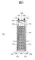
- FIG. 1 schematically shows the internal structure of an embodiment of a lithium secondary battery according to the present invention.
- the lithium secondary battery 101 is an electrochemical device that can store or use electrical energy by occlusion / release of lithium ions to and from an electrode in a nonaqueous electrolyte. This is called by another name of a lithium ion battery, a non-aqueous electrolyte secondary battery, and a non-aqueous electrolyte secondary battery, but any battery is also the subject of the present invention.
- the lithium secondary battery 101 has a configuration in which an electrode group including a positive electrode 107, a negative electrode 108, and a semi-solid electrolyte layer 109 is housed in a battery container 102 in a sealed state.
- the semi-solid electrolyte layer 109 is formed at least on the surface of the positive electrode 107 or the negative electrode 108 and has an integral structure.
- the semi-solid electrolyte layer 109 has a function of electrically permeating lithium ions by electrically insulating the positive electrode 107 and the negative electrode 108 and holding an ionic liquid or glyme and a lithium salt as an electrolyte.
- the electrode group can adopt various configurations such as a configuration in which strip-shaped electrodes are stacked, a configuration in which a strip-shaped electrode is wound and formed into a cylindrical shape or a flat shape.
- the battery container 102 can have any shape such as a cylindrical shape, a flat oval shape, a square shape, or the like corresponding to the shape of the electrode group.
- the battery case 102 accommodates the electrode group from the opening provided in the upper part, and then the opening is closed and sealed by the lid 103.
- the lid 103 is joined to the opening of the battery container 102 by, for example, welding, caulking, adhesion, or the like, and the battery container 102 is sealed in a hermetically sealed manner, for example, by outer periphery.
- the lid 103 has a liquid injection port for injecting the constituent components of the semi-solid electrolyte layer 109 into the battery container 102 after sealing the opening of the battery container 102.
- the liquid injection port is sealed with a liquid injection plug 106 after the components of the semi-solid electrolyte layer 109 are injected into the battery container 102.
- a safety mechanism to the liquid filling plug 106.
- a pressure valve for releasing the pressure inside the battery container 102 may be provided.
- a positive electrode external terminal 104 and a negative electrode external terminal 105 are fixed to the lid 103 via an insulating seal member 112, and a short circuit between both terminals (the positive electrode external terminal 104 and the negative electrode external terminal 105) is prevented by the insulating seal member 112. .
- the positive external terminal 104 is connected to the positive electrode 107 via the positive lead 110 and the negative external terminal 105 is connected to the negative 108 via the negative lead 111.
- the material of the insulating seal member 112 can be selected from fluororesins, thermosetting resins, glass hermetic seals, etc., and any insulating material that does not react with the constituent components of the solid electrolyte layer 109 and has excellent airtightness. Can be used.
- the insulating sheet 113 is also inserted between the electrode group and the battery container 102 so that the positive electrode 107 and the negative electrode 108 are not short-circuited through the battery container 102.
- the positive electrode 107 includes a positive electrode active material, a conductive agent, a binder, and a current collector.
- the positive electrode active material include LiCoO 2 , LiNiO 2 , and LiMn 2 O 4 .
- LiMnO 3 , LiMn 2 O 3 , LiMnO 2 , Li 4 Mn 5 O 12 , LiMn 2 ⁇ x M x O 2 (where M is one or more selected from Co, Ni, Fe, Cr, Zn, and Ta) X is 0.01 to 0.2
- Li 2 Mn 3 MO 8 where M is one or more selected from Fe, Co, Ni, Cu and Zn
- Li 1-x A x Mn 2 O 4 (where A is one or more selected from Mg, B, Al, Fe, Co, Ni, Cr, Zn and Ca, and x is 0.01 to 0.1)
- LiNi 1 -X M x O 2 where M is one or more selected from Co, Fe and Ga, and x is 0.01 to 0.2
- LiFeO 2 , Fe 2 (SO 4 ) 3 LiCo 1 -x M x O 2 (however, M is Ni, Fe and M And at one or more selected from, x is a 0.01 ⁇ 0.2)
- LiNi 1/3 Mn 1/3 Co 1/3 O 2 is preferably used as the positive electrode active material.
- the lithium secondary battery of this embodiment is not limited to the positive electrode material, and is not limited to these materials.
- a Li 2 MnO 3 —LiMnO 2 solid solution positive electrode having a higher capacity than that, and a high power 5V positive electrode ( LiNi 0.5 Mn 1.5 O 4 etc.) may also be used.
- these high capacity materials or high power materials are used, the thickness of the positive electrode mixture layer can be reduced, and the electrode area that can be accommodated in the battery can be increased. As a result, the resistance of the battery can be reduced to enable high output, and at the same time, the capacity of the battery can be increased as compared with the case of using a LiNi 1/3 Co 1/3 Mn 1/3 O 2 positive electrode.
- the positive electrode 107 When producing the positive electrode 107, first, it is preferable to collect a powder of secondary particles (granulated primary particles) of the positive electrode active material.
- primary powder may be used without granulation, such as lithium iron phosphate. The presence or absence of granulation and the difference between primary particles and secondary particles are not important in this embodiment.
- the particle size of the positive electrode active material is specified to be equal to or less than the thickness of the mixture layer.
- the coarse particles are removed in advance by sieving classification, wind classification, etc., to produce particles having a thickness of the mixture layer or less. .
- the average particle diameter (D 50 ) of the positive electrode active material in the present embodiment is measured by a laser scattering method.
- the presence or absence of granulation of the active material particles and the difference between the primary particles and the secondary particles are not important in this embodiment.Therefore, the crushing treatment is not performed before the measurement of the average particle size, and the actual use state is not used. Analyze the powder.
- the average particle diameter D 50 is a sample of the positive electrode active material was suspended in water, a laser scattering type particle size measuring apparatus (for example, Microtrac) can be measured using the.
- D 50 is defined as the particle size when the ratio (volume fraction) to the volume of the entire sample is 50%. The range is preferably 2 ⁇ m or more and 20 ⁇ m or less.
- the average particle size (D 50 ) is in the range of 2 ⁇ m or more and 10 ⁇ m or less, the balance of the electrolyte holding capacity is improved while preventing the deterioration of the filling property of the active material in the positive electrode accompanying the particle size reduction. It is possible to provide a positive electrode with good quality.
- the average pore diameter in the positive electrode mixture layer is in a suitable range of 0.01 ⁇ m or more and 0.6 ⁇ m or less after the positive electrode is manufactured, and the electrolyte holding ability is improved.
- the average pore diameter in the positive electrode mixture layer is the pore diameter of voids formed in the mixture layer composed of an aggregate of the positive electrode active material, the conductive agent and the binder. As will be described later, when the electrolyte solvent is also retained in the positive electrode, it is the pore diameter of the void excluding the electrolyte solvent.
- the average pore diameter can be measured by the following means. First, an electrolyte solvent component such as glyme is eluted using a low-viscosity organic solvent or water. Specifically, when the positive electrode is immersed in alcohol such as methanol or ethanol, dimethyl ether, acetone, dimethoxyethane, or water, the electrolyte solvent is eluted from the positive electrode.
- the positive electrode is taken out and dried in vacuum to remove the low-viscosity organic solvent or water, and the electrolyte solvent is removed from the pores of the positive electrode mixture layer.
- the pore diameter is measured using a mercury porosimeter. In this embodiment, the median diameter is the average pore diameter.
- the positive electrode slurry is prepared by dispersing a mixture of a positive electrode active material, a conductive agent and a binder in a solvent.
- a positive electrode active material e.g., acetylene black, a mixture of acetylene black and carbon nanotube (CNT), or the like can be used.
- CNT carbon nanotube
- any binder that does not decompose on the positive electrode surface and does not dissolve in the electrolyte solvent can be used.
- PVDF polyvinylidene fluoride
- a binder of styrene butadiene rubber and carboxymethyl cellulose may be used instead of PVDF or the like.
- fluorine rubber, ethylene / propylene rubber, polyacrylic acid, polyimide, polyamide and the like can be used as the binder, and are not particularly limited.
- the inert particles in the present invention may be added to the positive electrode mixture layer.
- the addition amount is desirably in the range of 0.1 to 5% by weight, and more desirably in the range of 0.1 to 1% by weight with respect to the entire mixture layer. If the addition amount of the inert particles is too small, the electrolyte holding power is reduced to the same extent as the electrode without addition. On the other hand, if the addition amount is too large, the resistance of the positive electrode 107 increases due to the insulating properties of the inert particles, and the charge / discharge capacity of the positive electrode decreases, which is not preferable.
- the inert particles include SiO 2, Al 2 O 3, AlOOH, TiO 2, ZrO 2, BaTiO 3 and Li 7 La 3 1 or more compounds selected from the group consisting of Zr 2 O 12 .
- the average particle diameter of the inert particles is defined as the particle diameter (D 50 ) when the ratio (volume fraction) to the volume of the entire sample is 50%, similarly to the average particle diameter of the positive electrode active material.
- the average particle diameter (D 50 ) of the inert particles is measured by a laser scattering method. Specifically, a sample of inert particles is suspended in water, and a laser scattering particle size measuring device (for example, Microtrac) is used. Can be measured.
- the solvent used for preparing the slurry may be any solvent that can dissolve the binder, and 1-methyl-2-pyrrolidone or the like can be used for PVDF.
- a solvent is selected according to the type of the binder.
- a known kneader or disperser can be used for the dispersion treatment of the positive electrode active material, the conductive agent, and the binder.
- the positive electrode 107 can be manufactured. Moreover, it is also possible to laminate a plurality of mixture layers on the current collector by repeating from application to drying a plurality of times.
- the current collector may be an aluminum foil having a thickness of 10 ⁇ m to 100 ⁇ m, or an aluminum perforated foil having a thickness of 10 ⁇ m to 100 ⁇ m and a hole diameter of 0.1 mm to 10 mm, an expanded metal, a foam metal plate, etc.
- aluminum, stainless steel, titanium, etc. are applicable.
- any material can be used for the current collector as long as it does not change during the use of the battery, such as dissolution and oxidation, without being limited by the material, shape, manufacturing method, and the like. .
- the thickness of the positive electrode mixture layer is desirably equal to or greater than the average particle diameter of the positive electrode active material, and specifically, is preferably in the range of 20 ⁇ m to 80 ⁇ m. If the positive electrode mixture layer is too thick, unless the conductive agent is added in a large amount to the positive electrode mixture layer, the charge level of the positive electrode active material near the surface of the mixture layer and the current collector surface will vary, resulting in uneven charge / discharge happenss. Further, increasing the amount of the conductive agent is not preferable because the positive electrode volume becomes bulky and the energy density of the battery decreases.
- mixture density of the positive electrode mixture layer is preferably 3 g / cm 3 or more. It is necessary to reduce the electronic resistance of the mixture layer by bringing the conductive agent and the positive electrode active material into close contact with each other.
- the negative electrode 108 includes a negative electrode active material, a binder, and a current collector.
- the negative electrode active material is not particularly limited, and natural graphite coated with amorphous carbon is preferably used.
- silicon, tin, or a compound thereof (oxide, nitride, and alloy with other metals) may be used for the negative electrode active material.
- These active materials are larger than the theoretical capacity of graphite (372 Ah / kg), and a capacity of 500 to 1500 Ah / kg is obtained.
- the mixture thickness of the negative electrode can be reduced, and the electrode area that can be accommodated in the battery can be increased.
- the resistance of the battery can be reduced to enable high output, and at the same time, the capacity of the battery can be increased as compared with the case where a graphite negative electrode is used.
- a method of forming amorphous carbon on the surface of natural graphite there is a method of depositing pyrolytic carbon on the negative electrode active material powder. Specifically, by diluting a low-molecular hydrocarbon such as ethane, propane, or butane with an inert gas such as argon and heating to 800 to 1200 ° C., hydrogen is generated from the hydrocarbon on the surface of the negative electrode active material particles. It desorbs and carbon is deposited on the surface of the negative electrode active material particles. Carbon is an amorphous form. As another method, after adding an organic substance such as polyvinyl alcohol or sucrose, heat treatment is performed at 300 to 1000 ° C.
- an organic substance such as polyvinyl alcohol or sucrose
- the average particle diameter (D 50 ) of the negative electrode active material in the present embodiment is measured by a laser scattering method.
- the average particle diameter D 50 is a sample of the negative electrode active material was suspended in water, a laser scattering type particle size measuring apparatus (for example, Microtrac) can be measured using the.
- D 50 is defined as the particle size when the ratio (volume fraction) to the volume of the entire sample is 50%.
- the range is preferably in the range of 5 ⁇ m to 20 ⁇ m.
- the average pore diameter in the negative electrode mixture layer becomes a suitable range of 0.01 ⁇ m or more and 0.6 ⁇ m or less after the preparation of the negative electrode, and the retention capacity of the electrolyte is improved.
- the average pore diameter in the negative electrode mixture layer is the pore diameter of voids formed in the mixture layer composed of the negative electrode active material and the binder. As will be described later, when the electrolyte solvent is also retained in the negative electrode, the pore diameter is the pore size excluding the electrolyte solvent.
- the average pore diameter is measured by the same method as the average pore diameter in the positive electrode mixture layer described above. If a conductive agent is added, it shall be removed. The pore diameter can be measured using a mercury porosimeter. In this embodiment, the median diameter is the average pore diameter.
- the negative electrode slurry is prepared by dispersing a mixture of a negative electrode active material and a binder in a solvent.
- a conductive agent such as acetylene black may be mixed as necessary.
- any binder that does not decompose on the surface of the negative electrode and does not dissolve in the electrolyte solvent can be used.
- PVDF polyvinylidene fluoride
- a binder of styrene butadiene rubber and carboxymethyl cellulose may be used instead of PVDF or the like.
- fluorine rubber, ethylene / propylene rubber, polyacrylic acid, polyimide, polyamide and the like can be used as the binder, and are not particularly limited.
- the inert particles in the present invention may be added to the negative electrode mixture layer, as in the case of the positive electrode.
- the addition amount is desirably in the range of 0.1 to 5% by weight, and more desirably in the range of 0.1 to 1% by weight with respect to the entire mixture layer. If the addition amount of the inert particles is too small, the electrolyte holding power is reduced to the same extent as the electrode without addition. On the other hand, if the addition amount is too large, the resistance of the negative electrode 108 increases and the charge / discharge capacity of the negative electrode decreases due to the insulating properties of the inert particles.
- the inert particles include SiO 2, Al 2 O 3, AlOOH, TiO 2, ZrO 2, BaTiO 3 and Li 7 La 3 1 or more compounds selected from the group consisting of Zr 2 O 12 .
- About the average particle diameter of an inert particle it is the same as that of the case of a positive electrode, and it is preferable that they are 0.1 micrometer or more and 5 micrometers or less.
- the solvent used for preparing the slurry may be any solvent that dissolves the binder, and 1-methyl-2-pyrrolidone or the like can be used for the PVDF binder.
- a binder of styrene butadiene rubber and carboxymethyl cellulose water can be used as a solvent, and the solvent is selected according to the type of the binder.
- a known kneader or disperser can be used for the dispersion treatment of the negative electrode active material and the binder.
- a negative electrode slurry mixed with a negative electrode active material, a binder and a solvent By adhering a negative electrode slurry mixed with a negative electrode active material, a binder and a solvent to a current collector by a doctor blade method, a dipping method, a spray method, etc., and then drying the solvent and pressing the negative electrode by a roll press.
- the negative electrode 108 can be manufactured.
- a plurality of mixture layers can be laminated on the current collector by repeating a plurality of times from application to drying.
- a copper foil having a thickness of 10 ⁇ m or more and 100 ⁇ m or less, a copper perforated foil having a thickness of 10 ⁇ m or more and 100 ⁇ m or less, a pore diameter of 0.1 mm or more and 10 mm or less, an expanded metal, a metal foam plate, etc. are used.
- copper, stainless steel, titanium, nickel and the like are also applicable.
- any current collector can be used without being limited by the material, shape, manufacturing method, and the like.
- the thickness of the negative electrode mixture layer is desirably greater than or equal to the average particle diameter of the negative electrode active material, specifically 10 ⁇ m or more, preferably 15 ⁇ m or more, and preferably 50 ⁇ m or less. This is because, when the thickness is an average particle diameter, the electron conductivity between adjacent particles is deteriorated. If the negative electrode mixture layer is too thick, unless the conductive agent is added in a large amount to the negative electrode mixture layer, the charge level of the negative electrode active material near the surface of the mixture layer and the current collector surface will vary, resulting in uneven charge / discharge happenss. Also, increasing the amount of the conductive agent is not preferable because the negative electrode volume becomes bulky and the energy density of the battery decreases.
- the electrolyte can be retained by adding the electrolyte to the positive electrode or the negative electrode and absorbing it into the pores of the electrode (electrolyte L in FIG. 1). .
- a slurry in which an electrolyte, an active material, a binder, and the like are mixed can be prepared, and this slurry can be applied together on a current collector.
- the electrolyte includes an electrolyte solvent and a lithium salt.
- the lithium salt include imide salts such as Li (NSO 2 F) 2 (LiFSI) or LiN (SO 2 CF 3 ) 2 (LiTFSI), LiC 4 BO 8 (lithium bisoxalate borate), and CF 3 SO 3.
- imide salts such as Li (NSO 2 F) 2 (LiFSI) or LiN (SO 2 CF 3 ) 2 (LiTFSI), LiC 4 BO 8 (lithium bisoxalate borate), and CF 3 SO 3.
- Examples thereof include Li (lithium trifluoromethanesulfonate), LiBF 4 (lithium borofluoride), LiPF 6 (lithium hexafluorophosphate), and the like. Any of these may be used alone or in combination.
- the concentration of the lithium salt is preferably 1 mol or more and 3 mol or less with respect to 1 liter of the electrolyte solvent.
- Formula 1 RO- (CH 2 CH 2 O) n -R (In Formula 1, R is an alkyl group having 1 to 4 carbon atoms, and n is an integer of 1 to 4)
- R is an alkyl group having 1 to 4 carbon atoms
- n is an integer of 1 to 4
- the glyme represented by these can be used.
- an ionic liquid can be used as the electrolyte solvent.
- the ionic liquid can be appropriately selected from various compounds.
- EMI-BTI 1-ethyl-3-methylimidazolium bis (trifluoromethylsulfonyl) imide
- EMI-TMS 1-ethyl-3-methylimidazo Lithium trifluoromethanesulfonate
- BMP-BTI 1-butyl-1-methylmethylpyrrolidinium bis (trifluoromethylsulfonyl) imide
- HMI- HFP 1-ethyl-3-methylimidazolium dicyanamide
- MOI-TFB 11-methyl-3-octylimidazolium tetrafluoroborate
- a lithium salt such as LiFSI or LiTFSI is added to these ionic liquids, a higher conductivity can be obtained than when glyme is used as the electrolyte solvent.
- the use of glyme is disadvantageous in terms of conductivity compared to ionic liquids, but has an advantage that the environmental load at the time of electrolyte leakage is small and the recycling cost can be reduced.
- a semi-solid electrolyte layer 109 is inserted between the positive electrode 107 and the negative electrode 108 to enable exchange of lithium ions between the electrodes.
- the semi-solid electrolyte layer 109 has pores formed by aggregates of inert particles, and the ionic liquid or glyme as an electrolyte solvent and a lithium salt are held therein.
- the inert particles one or more compounds selected from the group consisting of SiO 2 , Al 2 O 3 , AlOOH, TiO 2 , ZrO 2 , BaTiO 3 and Li 7 La 3 Zr 2 O 12 are preferably used.
- the average particle diameter of the inert particles is the same as that of the positive electrode and the negative electrode, and is preferably 0.1 ⁇ m or more and 5 ⁇ m or less.
- the volume fraction of the inert particles in the semi-solid electrolyte layer 109 is 33% or more and 80% or less. Preferably, it is 33% or more and 44% or less.
- the volume fraction of inert particles can be controlled by the amount of inert particles added. If the volume fraction is less than 33%, the amount of electrolyte retained decreases and liquid leakage tends to occur, and if it exceeds 80%, the relative amount of electrolyte decreases and the conductivity decreases, which is not possible.
- the average pore diameter of the semi-solid electrolyte layer 109 is set to 0.01 ⁇ m or more and 0.6 ⁇ m or less. Preferably they are 0.01 micrometer or more and 0.25 micrometer or less. Within this range, the electrolyte solvent and lithium salt necessary for the exchange of lithium ions are retained, and it becomes possible to provide an electrolyte layer with low resistance.
- the pore diameter of the semi-solid electrolyte layer can be controlled by the amount of inert particles added.
- the pore diameter of the semi-solid electrolyte layer can also be measured by the same procedure as that for measuring the pore diameter of the positive or negative electrode mixture layer using a mercury porosimeter. That is, an electrolyte solvent component such as glyme is eluted by immersing the semi-solid electrolyte layer in an alcohol such as methanol or ethanol, a low viscosity organic solvent such as dimethyl ether, acetone or dimethoxyethane, or water.
- an electrolyte solvent component such as glyme is eluted by immersing the semi-solid electrolyte layer in an alcohol such as methanol or ethanol, a low viscosity organic solvent such as dimethyl ether, acetone or dimethoxyethane, or water.
- the semi-solid electrolyte layer is taken out and dried in vacuum to remove the low-viscosity organic solvent or water, and the electrolyte solvent is removed from the pores of the semi-solid electrolyte layer can get.
- the pore diameter is measured using a mercury porosimeter. In this embodiment, the median diameter is the average pore diameter.
- the average value of the center-to-center distance of the inert particles contained in the semi-solid electrolyte layer 109 is 1 to 5 times the average particle diameter of the inert particles.
- the distance between the centers of the inert particles can be determined by a method in which the outer edges of the particles are approximated by a circle and the distance between the centers is measured, and the above average value is calculated between three randomly acquired centers. This is the average distance.
- the thickness of the semi-solid electrolyte layer 109 is 1 ⁇ m or more and 100 ⁇ m or less, and more preferably 5 ⁇ m or more and 25 ⁇ m or less. If the thickness is too thin, pinholes are formed in the semi-solid electrolyte layer, and a short circuit between the positive electrode and the negative electrode is likely to occur. Conversely, if the thickness is too thick, the movement distance of lithium ions becomes too large, and lithium ions between the positive electrode and the negative electrode Since the resistance required for the movement increases, it is set appropriately in consideration of these balances.
- the semi-solid electrolyte layer 109 may be produced directly on the positive electrode 107 or the negative electrode 108. Alternatively, after a semi-solid electrolyte layer is formed on a resin or metal support sheet, the semi-solid electrolyte layer may be peeled off from the support sheet and attached to the positive electrode 107 or the negative electrode 108 for lamination.
- NMP 1-methyl-2-pyrrolidone
- the semi-solid electrolyte layer 109 can be obtained by mixing the solvent, applying the slurry to the surface of the positive electrode or the negative electrode, and removing NMP by drying. After the semi-solid electrolyte layer 109 is formed, it may be compressed by a roll press or may be omitted.
- a binder such as polyvinylidene fluoride or tetrafluoroethylene to the slurry as necessary because the mechanical strength of the semi-solid electrolyte layer 109 is increased.
- a lower alcohol such as ethanol or water may be used.
- the positive electrode 107 or the negative electrode 108 on which the semi-solid electrolyte layer 109 is formed and the other electrode (the negative electrode 108 or the positive electrode 107) are stacked to constitute an electrode group.
- the semi-solid electrolyte layer 109 may be formed on any surface of the positive electrode 107 and the negative electrode 108 or both.
- the semi-solid electrolyte layer 109 functions as a medium for moving lithium ions between the positive electrode and the negative electrode while preventing a short circuit between the positive electrode 107 and the negative electrode 108.
- An insulating sheet 113 is inserted between the electrode disposed at the end of the electrode group and the battery container 102 so that the positive electrode 107 and the negative electrode 108 are not short-circuited through the battery container 102.
- the upper part of the laminate is electrically connected to an external terminal via a lead wire.
- the positive electrode 107 is connected to the positive electrode external terminal 104 of the lid 103 via the positive electrode lead wire 110.
- the negative electrode 108 is connected to the negative electrode external terminal 105 of the lid 103 via the negative electrode lead wire 111.
- the positive electrode lead wire 110 and the negative electrode lead wire 111 can take arbitrary shapes, such as wire shape and plate shape. If the material can reduce ohmic loss when a current is passed and does not react with the electrolyte, the shape and material of the positive electrode lead wire 110 and the negative electrode lead wire 111 depend on the structure of the battery case 102. Can be arbitrarily selected.
- the material of the battery container 102 is appropriately selected from materials that are corrosion resistant to the electrolyte, such as aluminum, stainless steel, and nickel-plated steel.
- the lid 103 is brought into close contact with the battery container 102 and the whole battery is sealed.
- the lid 103 can be attached to the battery container 102 by caulking.
- a known technique such as welding or adhesion may be applied to the method for sealing the battery.
- the liquid injection plug 106 is used when an electrolyte is added to the positive electrode 107 or the negative electrode 108, but the liquid injection plug 106 is unnecessary when the electrolyte is held in advance by the electrode.
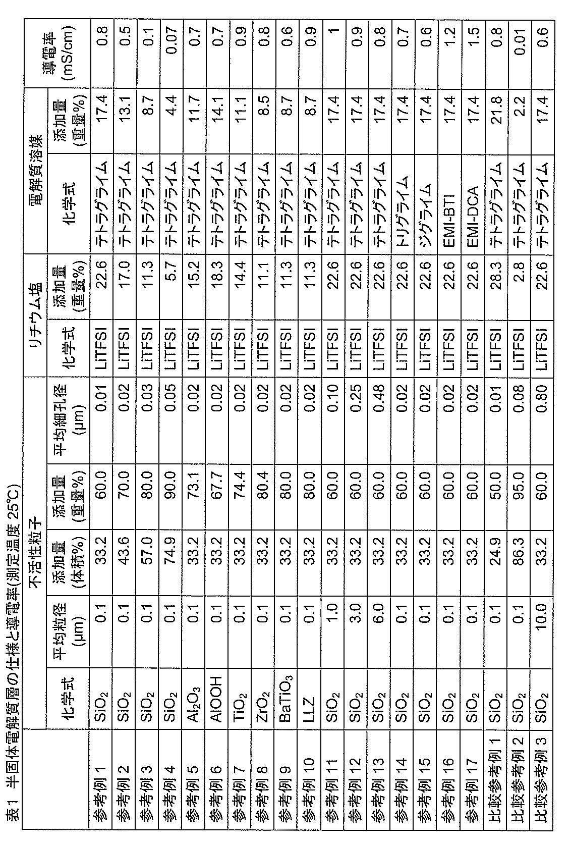
- the average pore diameter was measured using a mercury porosimeter.
- the column of lithium salt in Table 1 shows the type of lithium salt used in each example and the amount added (expressed in weight%) in the semi-solid electrolyte layer, and the column of electrolyte solvent used in the column of electrolyte solvent (Chemical formula) and the addition amount in the semi-solid electrolyte layer are described.
- the concentration of the lithium salt relative to 1 liter of electrolyte solvent was 2 mol.
- the conductivity column of Table 1 shows the measured value of the conductivity of the semisolid electrolyte layer at 25 ° C., and the conductivity was calculated from the resistance value by inserting the semisolid electrolyte layer between two metallic lithiums. .
- Reference Example 1 to Reference Example 4 are the results of evaluating the relationship between the amount of addition and the electrical conductivity when the inert particles are SiO 2 .
- the volume fraction of SiO 2 is in the range of 33.2% to 74.9%
- the average pore diameter of the semi-solid electrolyte layer is in the range of 0.01 ⁇ m to 0.05 ⁇ m, and leakage of lithium salts and electrolyte solvents A semi-solid electrolyte layer free from the above could be produced.
- the electrical conductivity tended to increase as the SiO 2 addition amount decreased, that is, as the addition amount of the electrolyte (lithium salt and electrolyte solvent) increased.
- the semi-solid electrolyte layer of this reference example was inserted between two medicine-wrapped papers or a polyethylene porous separator and pressurized.
- the applied pressure was 3 MPa per unit area of the semi-solid electrolyte layer. Since the weight of the medicine wrapping paper and the polyethylene porous separator did not change, it was confirmed that there was no liquid leakage.
- the average particle diameter of SiO 2 was changed, and the average pore diameter of the semi-solid electrolyte layer was set to 0.10 ⁇ m or more and 0.48 ⁇ m or less.
- the addition amount of SiO 2 was equal to the addition amount of Reference Example 1.
- the average pore diameter of the semi-solid electrolyte layer was 0.48 ⁇ m, there was no leakage of the lithium salt and the electrolyte solvent.
- Reference Example 14 and Reference Example 15 are the results of changing the electrolyte solvent to triglyme and diglyme. Compared to Reference Example 1, the electrical conductivity was the same, and there was no leakage of lithium salt and electrolyte solvent.
- Comparative Reference Example 1 and Comparative Reference Example 2 examined the case where the volume fraction was reduced (Comparative Reference Example 1) and the case where the volume fraction was increased (Comparative Reference Example 2) using the SiO 2 of Example 1. It is a result.
- Comparative Reference Example 1 the conductivity was almost the same as that of Reference Example 1. However, it was unsuitable from the result of a liquid leakage test as a lithium secondary battery described later (Table 2).
- Comparative Reference Example 2 the amount of SiO 2 added was excessive, and the conductivity was significantly reduced.
- Comparative Reference Example 3 is the result of increasing the average particle diameter of SiO 2 and increasing the average pore diameter (0.80 ⁇ m).
- the conductivity was the same level as in Reference Example 1. However, it was unsuitable based on the result of a liquid leakage test as a lithium secondary battery described later (Table 2).
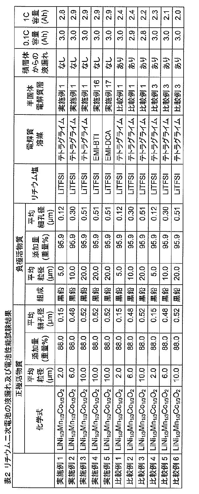
- a lithium secondary battery was produced by laminating the semisolid electrolyte shown in Table 1 with an electrode, and a liquid leakage test from the laminate and measurement of battery performance were performed.
- the results are shown in Table 2.
- Examples 1 to 5 in Table 2 summarize the results of the configuration of the present invention.
- the type (chemical formula) of the positive electrode active material, the average particle diameter, the addition amount in the positive electrode mixture layer, and the average pore diameter are shown.
- the positive electrode active material was 88% by weight
- the conductive agent was 5% by weight
- the PVDF (polyvinylidene fluoride) binder was 7% by weight in 100% by weight of the components constituting the mixture layer.
- the conductive agent a mixture of acetylene black and carbon nanotubes (CNT) was used, and the respective weight compositions were 4.7% by weight and 0.3% by weight.
- the specifications of the negative electrode active material are shown in Table 2.
- the negative electrode active material is 95.9% by weight
- the conductive agent is 0.1% by weight
- the PVDF (polyvinylidene fluoride) binder is 4% in 100% by weight of the components constituting the mixture layer. % By weight.
- the negative electrode active material a material in which 2% by weight of carbon was precipitated on the graphite surface was used.
- carbon nanotubes (CNT) were used as the conductive agent.
- Table 2 shows the presence or absence of liquid leakage when a load of 5 MPa is applied in a direction perpendicular to the plane (for example, the entire back surface of the positive electrode) to a laminate in which a semi-solid electrolyte layer is inserted between the positive electrode and the negative electrode. The verified result is shown. The presence or absence of liquid leakage was judged from the presence or absence of the lithium salt or electrolyte solvent exudation by wiping the end of the laminate with a nonwoven fabric.
- Example 1 to Example 5 it was found that there was no liquid leakage from the laminate, and the electrolyte and the like were held on the electrodes.
- the results of measuring the discharge capacity by charge / discharge of 0.1 C with respect to the design capacity 3 Ah of the battery are shown in the column of “0.1 C capacity” in Table 2.
- the current was set to 0.3A, and charging was performed at a constant current of 0.3A until reaching 4.2V. After reaching 4.2V, charging was performed at a constant voltage of 4.2V until reaching 0.03A. Thereafter, the battery was discharged at a constant current of 0.3 A until the battery voltage reached 2.8 V, and the obtained discharge capacity was defined as “0.1 C capacity”. Under this condition, since the rate is low, it is desirable to obtain a design capacity.
- a design capacity of 3 Ah is obtained.
- Comparative Examples 1 to 3 are the results when the semi-solid electrolyte layer of Comparative Reference Example 1 was used. In the case of this configuration, there was a liquid leakage of the semisolid electrolyte layer. This is probably because the lithium salt and electrolyte solvent exuded by pressurization because the amounts of lithium salt and electrolyte solvent contained in the semi-solid electrolyte layer were too large.
- Comparative Example 4 to Comparative Example 6 show the results when the semi-solid electrolyte layer of Comparative Reference Example 3 is used. Even in this configuration, there was a liquid leakage of the semi-solid electrolyte layer. This is probably because the semi-solid electrolyte has a large SiO 2 particle size and an average pore size that is too large, so that the ability to retain the lithium salt and the electrolyte solvent has decreased.
Abstract
Description
(リチウム二次電池の構成)
図1は、本発明に係るリチウム二次電池の一実施形態の内部構造を模式的に示している。リチウム二次電池101は、非水電解質中における電極へのリチウムイオンの吸蔵・放出により、電気エネルギーを貯蔵又は利用可能とする電気化学デバイスである。これは、リチウムイオン電池、非水電解質二次電池、非水電解液二次電池の別の名称で呼ばれるが、いずれの電池も本発明の対象である。
正極107は、正極活物質、導電剤、バインダ、集電体から構成される。その正極活物質を例示すると、LiCoO2、LiNiO2、LiMn2O4が代表例である。他に、LiMnO3、LiMn2O3、LiMnO2、Li4Mn5O12、LiMn2-xMxO2(ただし、MはCo、Ni、Fe、Cr、Zn及びTaから選ばれる一以上であり、xは0.01~0.2である)、Li2Mn3MO8(ただし、MはFe、Co、Ni、Cu及びZnから選ばれる一以上である)、Li1-xAxMn2O4(ただし、AはMg、B、Al、Fe、Co、Ni、Cr、Zn及びCaから選ばれる一以上であり、xは0.01~0.1である)、LiNi1-xMxO2(ただし、MはCo、Fe及びGaから選ばれる一以上であり、xは0.01~0.2である)、LiFeO2、Fe2(SO4)3、LiCo1-xMxO2(ただし、MはNi、Fe及びMnから選ばれる一以上であり、xは0.01~0.2である)、LiNi1-xMxO2(ただし、MはMn、Fe、Co、Al、Ga、Ca及びMgから選ばれる一以上であり、xは0.01~0.2である)、Fe(MoO4)3、FeF3、LiFePO4、LiMnPO4等を挙げることができる。特に、LiNi1/3Mn1/3Co1/3O2は正極活物質として好ましく用いられる。ただし、本実施形態のリチウム二次電池では正極材料に何ら制約を受けないので、これらの材料に限定されない。LiNi1/3Co1/3Mn1/3O2の他に、それよりも高容量なLi2MnO3-LiMnO2系固溶体正極を用いることも可能であり、高電力量の5V系正極(LiNi0.5Mn1.5O4等)を用いても良い。これらの高容量材料又は高電力量材料を用いると、正極の合剤層の厚さを薄くすることができ、電池の中に収納可能な電極面積を増大させることができる。その結果、電池の抵抗を低下させて高出力が可能になると同時に、LiNi1/3Co1/3Mn1/3O2正極を用いたときよりも電池の容量を高めることができる。
負極108は、負極活物質、バインダ及び集電体から構成される。負極活物質としては、特に限定されるものではなく、非晶質炭素で被覆した天然黒鉛等が好ましく用いられる。その他、シリコンやスズ又はそれらの化合物(酸化物、窒化物、及び他の金属との合金)を負極活物質に用いても良い。これらの活物質は、黒鉛の理論容量(372Ah/kg)よりも大きく、500~1500Ah/kgの容量が得られる。これらの高容量材料を用いると、負極の合剤厚さを薄くすることができ、電池の中に収納可能な電極面積を増大させることができる。その結果、電池の抵抗を低下させて高出力が可能になると同時に、黒鉛負極を用いたときよりも電池の容量を高めることができる。
正極107又は負極108の細孔に電解質を充填するために、正極又は負極に電解質を添加し、電極の細孔に吸収させることにより、電解質を保持させることができる(図1中の電解質L)。具体的には、例えば、電解質、活物質及びバインダ等を混合したスラリを調製し、このスラリを集電体上に一緒に塗布することができる。
RO-(CH2CH2O)n-R
(式1中、Rは炭素数が1~4個のアルキル基であり、nは1~4の整数である。)
で表されるグライムを用いることができる。その中でも、トリグライム(n=3)、及びテトラグライム(n=4)は特に好ましく用いられる。これらのグライムは、いずれかを単独で、あるいは複数種を組み合わせて用いても良い。
正極107と負極108の間に、半固体電解質層109を挿入し、電極間のリチウムイオンの授受を可能にする。半固体電解質層109は、不活性粒子の集合体によって形成される細孔を有し、その中に電解質溶媒としての上述のイオン液体又はグライムと、リチウム塩とが保持されている。
半固体電解質層109を形成した正極107又は負極108と、他方の電極(負極108又は正極107)を積層して電極群を構成する。半固体電解質層109は正極107と負極108のいずれの表面に形成しても良く、両方に形成しても良い。半固体電解質層109は、正極107と負極108の短絡を防止しつつ、リチウムイオンを正極と負極間で移動させる媒体として機能する。
(参考例)
様々な組成による半固体電解質層を作製し、導電率を測定した。表1に、参考例1~17及び比較参考例1~3の半固体電解質層の仕様と導電率の測定結果を示す。表1の不活性粒子の欄には、半固体電解質層に用いた不活性粒子の種類(化学式)、平均粒径D50、半固体電解質層における添加量(単位は体積%と重量%を併記した。)及び半固体電解質層の平均細孔径を示した。平均細孔径は、水銀ポロシメータを用いて測定した。表1のリチウム塩の欄には、それぞれの例で使用したリチウム塩の種類と半固体電解質層における添加量(重量%で表示した)を示し、電解質溶媒の欄には採用した電解質溶媒の種類(化学式)と半固体電解質層における添加量を記載した。なお、電解質溶媒1リットルに対するリチウム塩の濃度は2モルとした。表1の導電率の欄には、25℃における半固体電解質層の導電率の測定値を示し、2枚の金属リチウムの間に半固体電解質層を挿入し、抵抗値より導電率を計算した。
102 電池容器
103 蓋
104 正極外部端子
105 負極外部端子
106 注液栓
107 正極
108 負極
109 半固体電解質層
110 正極リード線
111 負極リード線
112 絶縁シール部材
113 絶縁シート
L 電解質
Claims (4)
- 正極、負極及び半固体電解質層を含むリチウム二次電池において、
前記半固体電解質層は、イオン液体、及び下記式1
RO-(CH2CH2O)n-R (式1)
(式1中、Rは炭素数が1~4個のアルキル基であり、nは1~4の整数である。)
で表されるグライムから選択される電解質溶媒と、リチウム塩とを含み、
リチウムイオンを吸蔵・放出しない不活性粒子が、前記正極、負極及び半固体電解質層のうち、少なくとも前記半固体電解質層に含まれ、
前記正極、負極及び半固体電解質層は、細孔を有する多孔質構造であり、前記半固体電解質層では、前記細孔に前記電解質溶媒及びリチウム塩が保持され、前記細孔の平均細孔径が、0.01μm以上0.6μm以下であり、
前記半固体電解質層における前記不活性粒子の体積分率が、33%以上80%以下である、
前記リチウム二次電池。 - 前記不活性粒子の平均粒径が、0.1μm以上5μm以下である請求項1に記載のリチウム二次電池。
- 前記半固体電解質層に含まれる前記不活性粒子の中心間距離の平均値が、前記不活性粒子の平均粒径の1倍以上5倍以下である請求項1に記載のリチウム二次電池。
- 前記不活性粒子が、SiO2、Al2O3、AlOOH、TiO2、ZrO2、BaTiO3及びLi7La3Zr2O12からなる群から選択される1以上の化合物である請求項1に記載のリチウム二次電池。
Priority Applications (4)
| Application Number | Priority Date | Filing Date | Title |
|---|---|---|---|
| JP2018546217A JP6814225B2 (ja) | 2016-10-20 | 2017-09-28 | リチウム二次電池 |
| CN201780061559.7A CN109804494A (zh) | 2016-10-20 | 2017-09-28 | 锂二次电池 |
| KR1020197009315A KR20190042706A (ko) | 2016-10-20 | 2017-09-28 | 리튬 이차전지 |
| EP17861453.3A EP3531492A4 (en) | 2016-10-20 | 2017-09-28 | LITHIUM SECONDARY BATTERY |
Applications Claiming Priority (2)
| Application Number | Priority Date | Filing Date | Title |
|---|---|---|---|
| JP2016206148 | 2016-10-20 | ||
| JP2016-206148 | 2016-10-20 |
Publications (1)
| Publication Number | Publication Date |
|---|---|
| WO2018074174A1 true WO2018074174A1 (ja) | 2018-04-26 |
Family
ID=62018509
Family Applications (1)
| Application Number | Title | Priority Date | Filing Date |
|---|---|---|---|
| PCT/JP2017/035260 WO2018074174A1 (ja) | 2016-10-20 | 2017-09-28 | リチウム二次電池 |
Country Status (5)
| Country | Link |
|---|---|
| EP (1) | EP3531492A4 (ja) |
| JP (1) | JP6814225B2 (ja) |
| KR (1) | KR20190042706A (ja) |
| CN (1) | CN109804494A (ja) |
| WO (1) | WO2018074174A1 (ja) |
Cited By (6)
| Publication number | Priority date | Publication date | Assignee | Title |
|---|---|---|---|---|
| WO2019088197A1 (ja) * | 2017-11-02 | 2019-05-09 | アイメック・ヴェーゼットウェー | 固体電解質、電極、蓄電素子及び固体電解質の製造方法 |
| WO2019234977A1 (ja) * | 2018-06-08 | 2019-12-12 | 株式会社日立製作所 | 半固体電解質層及び二次電池 |
| JP2020053171A (ja) * | 2018-09-25 | 2020-04-02 | 株式会社日立製作所 | 非水電解液、不揮発性電解質、二次電池 |
| JP2021018860A (ja) * | 2019-07-18 | 2021-02-15 | 日本特殊陶業株式会社 | 蓄電デバイス |
| US11557789B2 (en) | 2017-11-02 | 2023-01-17 | Imec Vzw | Solid electrolyte, electrode, power storage device, and method for producing solid electrolytes |
| US11699810B2 (en) | 2017-04-24 | 2023-07-11 | Imec Vzw | Solid nanocomposite electrolyte materials |
Citations (4)
| Publication number | Priority date | Publication date | Assignee | Title |
|---|---|---|---|---|
| JP2011054519A (ja) * | 2009-09-04 | 2011-03-17 | Konica Minolta Holdings Inc | 固体電解質、その製造方法および二次電池 |
| JP2011119158A (ja) * | 2009-12-04 | 2011-06-16 | Toyota Motor Corp | 固体イオン伝導体、固体電解質膜、全固体リチウム二次電池 |
| JP2011192611A (ja) * | 2010-03-16 | 2011-09-29 | Sekisui Chem Co Ltd | 固液ハイブリッド電解質層 |
| JP2016508279A (ja) * | 2012-12-12 | 2016-03-17 | 三星エスディアイ株式会社Samsung SDI Co.,Ltd. | イオン性液体を含む固体電解質 |
Family Cites Families (19)
| Publication number | Priority date | Publication date | Assignee | Title |
|---|---|---|---|---|
| JP2000348710A (ja) * | 1999-06-07 | 2000-12-15 | Japan Energy Corp | 非水系二次電池用電極および製造方法 |
| JP4774941B2 (ja) * | 2005-11-14 | 2011-09-21 | ソニー株式会社 | ゲル電解質およびゲル電解質電池 |
| JP5359440B2 (ja) * | 2009-03-25 | 2013-12-04 | コニカミノルタ株式会社 | 電解質及び二次電池 |
| CN101552359A (zh) * | 2009-05-12 | 2009-10-07 | 湖南大学 | 一种用于锂离子电池的微纳多孔结构聚合物电解质膜及其制造方法 |
| CN102035043B (zh) * | 2009-09-25 | 2014-02-12 | 上海比亚迪有限公司 | 聚合物多孔膜、其制备方法、聚合物电解质及聚合物电池和电池的制备方法 |
| JP5705123B2 (ja) * | 2009-10-21 | 2015-04-22 | 国立大学法人京都大学 | ポリマー複合微粒子を用いた高分子固体電解質を用いた電気化学デバイス |
| CN102263290B (zh) * | 2010-05-31 | 2014-04-02 | 比亚迪股份有限公司 | 一种聚合物电池及其制备方法 |
| JP2012216500A (ja) * | 2011-03-30 | 2012-11-08 | Toyota Central R&D Labs Inc | リチウム二次電池 |
| JP2013030336A (ja) * | 2011-07-28 | 2013-02-07 | Toyota Motor Corp | リチウムイオン伝導体、及びリチウムイオン伝導膜 |
| WO2014000247A1 (zh) * | 2012-06-29 | 2014-01-03 | 海洋王照明科技股份有限公司 | 聚丙烯腈-甲基丙烯酸甲酯凝胶电解质膜的制备方法,及其相应电解质和制备方法 |
| KR102005448B1 (ko) | 2012-09-13 | 2019-07-31 | 삼성전자주식회사 | 리튬전지 |
| CN103668780B (zh) * | 2012-09-26 | 2016-02-03 | 比亚迪股份有限公司 | 聚合物膜、凝胶聚合物电解质和聚合物锂离子电池及其制备方法 |
| US10263279B2 (en) * | 2012-12-14 | 2019-04-16 | Sila Nanotechnologies Inc. | Electrodes for energy storage devices with solid electrolytes and methods of fabricating the same |
| CN103904329B (zh) * | 2012-12-27 | 2016-12-28 | 清华大学 | 锂离子电池 |
| CN104098785B (zh) * | 2013-04-07 | 2017-02-08 | 中国科学院长春应用化学研究所 | Pvdf凝胶聚合物电解质及其制备方法 |
| CN103545549B (zh) * | 2013-10-28 | 2015-07-22 | 北京理工大学 | 一种锂二次电池离子凝胶电解质及其制备方法 |
| US10205190B2 (en) * | 2014-08-28 | 2019-02-12 | Samsung Electronics Co., Ltd. | Composite electrolyte including polymeric ionic liquid and inorganic particles and lithium battery including the same |
| JP2016058282A (ja) * | 2014-09-10 | 2016-04-21 | 株式会社東芝 | 非水電解質電池 |
| KR102284480B1 (ko) * | 2014-12-05 | 2021-08-02 | 삼성에스디아이 주식회사 | 유무기 복합 전해질, 이를 포함하는 전극-전해질 접합체 및 리튬이차전지, 및 상기 전극-전해질 접합체의 제조방법 |
-
2017
- 2017-09-28 CN CN201780061559.7A patent/CN109804494A/zh active Pending
- 2017-09-28 JP JP2018546217A patent/JP6814225B2/ja active Active
- 2017-09-28 EP EP17861453.3A patent/EP3531492A4/en not_active Withdrawn
- 2017-09-28 WO PCT/JP2017/035260 patent/WO2018074174A1/ja unknown
- 2017-09-28 KR KR1020197009315A patent/KR20190042706A/ko active IP Right Grant
Patent Citations (4)
| Publication number | Priority date | Publication date | Assignee | Title |
|---|---|---|---|---|
| JP2011054519A (ja) * | 2009-09-04 | 2011-03-17 | Konica Minolta Holdings Inc | 固体電解質、その製造方法および二次電池 |
| JP2011119158A (ja) * | 2009-12-04 | 2011-06-16 | Toyota Motor Corp | 固体イオン伝導体、固体電解質膜、全固体リチウム二次電池 |
| JP2011192611A (ja) * | 2010-03-16 | 2011-09-29 | Sekisui Chem Co Ltd | 固液ハイブリッド電解質層 |
| JP2016508279A (ja) * | 2012-12-12 | 2016-03-17 | 三星エスディアイ株式会社Samsung SDI Co.,Ltd. | イオン性液体を含む固体電解質 |
Non-Patent Citations (3)
| Title |
|---|
| GAMBE, YOSHIYUKI ET AL., SCIENTIFIC REPORTS, vol. 5, 2015, XP055463157 * |
| See also references of EP3531492A4 * |
| UEMOTO, ATSUSHI ET AL., SOLID STATE IONICS, vol. 262, 2014, pages 765 - 768, XP055598146 * |
Cited By (9)
| Publication number | Priority date | Publication date | Assignee | Title |
|---|---|---|---|---|
| US11699810B2 (en) | 2017-04-24 | 2023-07-11 | Imec Vzw | Solid nanocomposite electrolyte materials |
| WO2019088197A1 (ja) * | 2017-11-02 | 2019-05-09 | アイメック・ヴェーゼットウェー | 固体電解質、電極、蓄電素子及び固体電解質の製造方法 |
| US11557789B2 (en) | 2017-11-02 | 2023-01-17 | Imec Vzw | Solid electrolyte, electrode, power storage device, and method for producing solid electrolytes |
| US11710850B2 (en) | 2017-11-02 | 2023-07-25 | Imec Vzw | Solid electrolyte, electrode, power storage device, and method for producing solid electrolytes |
| WO2019234977A1 (ja) * | 2018-06-08 | 2019-12-12 | 株式会社日立製作所 | 半固体電解質層及び二次電池 |
| JP2020053171A (ja) * | 2018-09-25 | 2020-04-02 | 株式会社日立製作所 | 非水電解液、不揮発性電解質、二次電池 |
| WO2020066058A1 (ja) * | 2018-09-25 | 2020-04-02 | 株式会社日立製作所 | 非水電解液、不揮発性電解質、二次電池 |
| JP2021018860A (ja) * | 2019-07-18 | 2021-02-15 | 日本特殊陶業株式会社 | 蓄電デバイス |
| JP7332371B2 (ja) | 2019-07-18 | 2023-08-23 | 日本特殊陶業株式会社 | 蓄電デバイス |
Also Published As
| Publication number | Publication date |
|---|---|
| JP6814225B2 (ja) | 2021-01-13 |
| KR20190042706A (ko) | 2019-04-24 |
| EP3531492A4 (en) | 2020-06-17 |
| JPWO2018074174A1 (ja) | 2019-08-29 |
| EP3531492A1 (en) | 2019-08-28 |
| CN109804494A (zh) | 2019-05-24 |
Similar Documents
| Publication | Publication Date | Title |
|---|---|---|
| WO2018074174A1 (ja) | リチウム二次電池 | |
| KR102309192B1 (ko) | 비수전해질 이차 전지용 부극재 및 부극 활물질 입자의 제조 방법 | |
| WO2012056765A1 (ja) | 二次電池及びその製造方法 | |
| JP2018195372A (ja) | リチウムイオン電池用電極組成物、その組成物を用いたリチウムイオン電池用電極及びリチウムイオン電池、並びにリチウムイオン電池用電極の製造方法 | |
| WO2018123324A1 (ja) | リチウムイオン二次電池用電極およびリチウムイオン二次電池 | |
| TW201841426A (zh) | 半固體電解質層、電池單元薄片及二次電池 | |
| WO2018230054A1 (ja) | 二次電池用電極、二次電池、それらの製造方法 | |
| JP7125891B2 (ja) | 二次電池及び二次電池の製造方法 | |
| KR102294200B1 (ko) | 반고체 전해액, 반고체 전해질, 반고체 전해질층 및 이차 전지 | |
| JP6843966B2 (ja) | 半固体電解液、半固体電解質、半固体電解質層、電極、二次電池 | |
| CN110521049B (zh) | 半固体电解质、电极、带有半固体电解质层的电极和二次电池 | |
| JP2019008893A (ja) | 二次電池用シート、半固体電解質層付き二次電池用電極、二次電池 | |
| JP6894973B2 (ja) | 半固体電解液、半固体電解質、半固体電解質層、電極および二次電池 | |
| JP2016081707A (ja) | 負極及びそれを用いたリチウムイオン二次電池 | |
| CN113169379A (zh) | 非水电解液、半固体电解质层、二次电池用片材和二次电池 | |
| CN112470319A (zh) | 非水电解液、非挥发性电解质和二次电池 | |
| JP2018116929A (ja) | 非水電解液二次電池 | |
| JP7272044B2 (ja) | 非水電解質、非水電解質蓄電素子、非水電解質の水溶性化剤、及び非水電解質の製造方法 | |
| WO2021065164A1 (ja) | 非水電解質二次電池 | |
| WO2020213268A1 (ja) | 非水電解液、不揮発性電解質、二次電池 | |
| WO2019087815A1 (ja) | 正極合剤層、正極、半二次電池、二次電池 | |
| JP2016081706A (ja) | 負極及びそれを用いたリチウムイオン二次電池 | |
| WO2019142502A1 (ja) | 負極、半二次電池、二次電池 | |
| KR20230159359A (ko) | 이차전지, 배터리 모듈, 배터리 팩 및 전기기기 | |
| CN112005419A (zh) | 绝缘层、单体电池片和电池 |
Legal Events
| Date | Code | Title | Description |
|---|---|---|---|
| 121 | Ep: the epo has been informed by wipo that ep was designated in this application |
Ref document number: 17861453 Country of ref document: EP Kind code of ref document: A1 |
|
| ENP | Entry into the national phase |
Ref document number: 20197009315 Country of ref document: KR Kind code of ref document: A |
|
| ENP | Entry into the national phase |
Ref document number: 2018546217 Country of ref document: JP Kind code of ref document: A |
|
| NENP | Non-entry into the national phase |
Ref country code: DE |
|
| ENP | Entry into the national phase |
Ref document number: 2017861453 Country of ref document: EP Effective date: 20190520 |