WO2018066216A1 - 払出装置 - Google Patents
払出装置 Download PDFInfo
- Publication number
- WO2018066216A1 WO2018066216A1 PCT/JP2017/027887 JP2017027887W WO2018066216A1 WO 2018066216 A1 WO2018066216 A1 WO 2018066216A1 JP 2017027887 W JP2017027887 W JP 2017027887W WO 2018066216 A1 WO2018066216 A1 WO 2018066216A1
- Authority
- WO
- WIPO (PCT)
- Prior art keywords
- unit
- tobacco product
- product
- tobacco
- information
- Prior art date
- Legal status (The legal status is an assumption and is not a legal conclusion. Google has not performed a legal analysis and makes no representation as to the accuracy of the status listed.)
- Ceased
Links
Images


Classifications
-
- G—PHYSICS
- G07—CHECKING-DEVICES
- G07F—COIN-FREED OR LIKE APPARATUS
- G07F11/00—Coin-freed apparatus for dispensing, or the like, discrete articles
- G07F11/02—Coin-freed apparatus for dispensing, or the like, discrete articles from non-movable magazines
- G07F11/04—Coin-freed apparatus for dispensing, or the like, discrete articles from non-movable magazines in which magazines the articles are stored one vertically above the other
- G07F11/16—Delivery means
- G07F11/165—Delivery means using xyz-picker or multi-dimensional article picking arrangements
-
- G—PHYSICS
- G07—CHECKING-DEVICES
- G07F—COIN-FREED OR LIKE APPARATUS
- G07F9/00—Details other than those peculiar to special kinds or types of apparatus
- G07F9/02—Devices for alarm or indication, e.g. when empty; Advertising arrangements in coin-freed apparatus
-
- G—PHYSICS
- G07—CHECKING-DEVICES
- G07F—COIN-FREED OR LIKE APPARATUS
- G07F9/00—Details other than those peculiar to special kinds or types of apparatus
- G07F9/02—Devices for alarm or indication, e.g. when empty; Advertising arrangements in coin-freed apparatus
- G07F9/026—Devices for alarm or indication, e.g. when empty; Advertising arrangements in coin-freed apparatus for alarm, monitoring and auditing in vending machines or means for indication, e.g. when empty
Definitions
- the present invention relates to a dispensing device that automatically dispenses tobacco products in response to a dispensing command.
- cigarette products mentioned here are not individual cigarettes used for smoking, but a rectangular parallelepiped package containing a plurality of cigarettes and other tobacco products as described later. Means the package.
- Patent Documents 1 to 5 describe devices for automatically dispensing tobacco products of a desired brand.
- the present invention has been made in view of the above-described problems, and provides a dispensing device capable of suitably supplementing tobacco products.
- a housing unit that houses a mixture of a plurality of types of tobacco products
- a dispensing unit that dispenses the tobacco product of the type corresponding to the dispensing instruction from the housing unit;
- a storage unit for storing the number of types stored
- An informing unit for informing the type of tobacco product to be replenished according to the remaining number of each type of tobacco product accommodated in the accommodating unit; Is provided.
- the tobacco commodities corresponding to the dispensing instruction can be automatically paid out by the dispensing portion.
- the tobacco product stored in the storage unit is stored with the number stored for each type, and the type of tobacco product to be replenished according to the remaining number for each type of tobacco product stored in the storage unit is notified. Therefore, it becomes possible to suitably replenish tobacco products by the operator.
- FIG. 5A and FIG. 5B are schematic views for explaining a moving mechanism that moves the transport unit.
- 6 (a) and 6 (b) are schematic front sectional views showing the delivery operation of the tobacco product from the transport unit to the carry-out slope.
- FIG. 16A and FIG. 16B are schematic views for explaining a moving mechanism that moves the transport unit.
- FIGS. 17A and 17B are schematic front cross-sectional views illustrating the delivery operation of tobacco products from the transport unit to the carry-out slope.
- FIG. 18A and FIG. 18B are schematic front views for explaining the delivery operation of tobacco products from the transport unit to the unqualified product storage tray performed through the unqualified product flow down slope. .
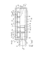
- FIGS. 1 and 2 are schematic views showing the structure of the dispensing device 100 according to the first embodiment, in which FIG. 1 is a front sectional view and FIG. 2 is a plan sectional view.
- 1 is a cross-sectional view taken along line II in FIG. 2
- FIG. 2 is a cross-sectional view taken along line II-II in FIG.
- the horizontal direction in FIGS. 1 and 2 is referred to as the X direction
- the vertical direction (height direction) is referred to as the Z direction.
- a direction orthogonal to the X direction and the Z direction, that is, the depth direction of the dispensing device 100 is referred to as a Y direction.
- 3 (a), 3 (b), 3 (c) and 3 (d) are schematic plan views showing the operation of taking out the tobacco product 40 from the storage column 11 (for example, the storage column 11d). is there.
- FIG. 4 (a), 4 (b) and 4 (c) are schematic views showing the operation of taking out the tobacco product 40 from the storage column 11 (for example, the storage column 11d), and the dispensing device 100 is viewed from the left side.
- FIG. FIG. 5A and FIG. 5B are schematic views for explaining a moving mechanism that moves the transport unit 50.
- 5A is a front view
- FIG. 5B is a cross-sectional view (plane cross-sectional view) taken along the line BB in FIG. 5A.
- FIG. 6A and FIG. 6B are schematic front sectional views showing the delivery (dispensing) operation of the tobacco product 40 from the transport unit 50 to the carry-out slope 92.
- FIG. 7 is a block diagram of the payout device 100 according to the first embodiment.
- FIG. 8 is a diagram illustrating an example of a replenishment threshold value (remaining number that needs to be replenished) for each type of tobacco product 40 and a replenishment number by one replenishment operation.
- FIG. 9 is a front view illustrating an example of a notification operation performed on the display unit 120. It should be noted that the various components of the present invention do not have to be individually independent, but one component is a part of another component, a part of one component and another component It is allowed to have some overlap.
- the dispensing device 100 accommodates a storage unit 10 that stores a mixture of a plurality of types of tobacco products 40 and a storage unit that stores a type of tobacco product 40 corresponding to a dispensing command. 10, a payout unit (conveying unit 50) that pays out from the storage unit 10, a storage unit (RAM 80 c in FIG. 7) that stores the number of types of tobacco products 40 stored in the storage unit 10, and the storage unit 10.
- a notification unit for example, the display unit 120 and the speaker 130 (FIG. 7)
- the payout device 100 is installed and used in a convenience store or other stores.
- the cigarette product 40 is not an individual cigarette used for smoking, but a rectangular parallelepiped package containing a plurality of cigarettes or a cuboid containing other tobacco products other than cigarettes. Means package. Examples of other tobacco products include snuff tobacco, pipe tobacco, and related articles such as suction tools used for these other tobacco products.
- the tobacco product 40 includes a rectangular first main surface 42, a rectangular second main surface 43 facing in parallel to the first main surface 42, a rectangular first side surface 44, and a second one.
- a side surface 45 (FIG. 2), a first end surface 46 and a second end surface 47 are provided.
- the first side surface 44 is disposed along one long side of the first main surface 42 and one long side of the second main surface 43, and with respect to the first main surface 42 and the second main surface 43. Are orthogonal.
- the second side surface 45 is disposed along the other long side of the first main surface 42 and the other long side of the second main surface 43, and with respect to the first main surface 42 and the second main surface 43. Are opposed to each other in parallel to the first side surface 44.
- the first end surface 46 is disposed along one short side of the first main surface 42 and one short side of the second main surface 43, and the first main surface 42, the second main surface 43, The first side surface 44 and the second side surface 45 are orthogonal to each other.
- the second end surface 47 is disposed along the other short side of the first main surface 42 and the other short side of the second main surface 43, and the first main surface 42, the second main surface 43, It is orthogonal to the first side surface 44 and the second side surface 45 and faces the first end surface 46 in parallel.
- the notification unit includes, for example, at least one of the display unit 120 (FIGS. 7 and 2) such as a liquid crystal display device or the speaker 130.
- the notification of the type of tobacco product 40 to be replenished is preferably performed by using both visual notification by display on the display unit 120 and auditory notification by pronunciation from the speaker 130.
- the notification unit notifies that the tobacco product 40 of that type should be replenished. That is, when the remaining number of one type of tobacco products 40 stored in the storage unit 10 reaches a predetermined number, the notification unit notifies that the type of tobacco products 40 should be replenished.
- the remaining number (the predetermined number) for which the tobacco product 40 needs to be supplemented is referred to as a supplement threshold.
- the replenishment threshold is determined for each type of tobacco product 40. For example, as shown in FIG. 8, the replenishment threshold is set to 5 for the tobacco product 40 of the type (brand) “A tobacco”, and the replenishment threshold is set for the tobacco product 40 of the type “B tobacco”. The threshold value is set to 2 and the replenishment threshold value is set to 0 for the tobacco product 40 of the type “C tobacco”. Thus, the predetermined number is set for each type of tobacco product 40.
- the notification by the notification unit preferably includes not only notification of the type of tobacco product 40 to be supplemented but also notification of the number of tobacco products 40 to be supplemented. That is, the notification unit notifies the number of tobacco products 40 to be replenished.
- the number of tobacco products 40 to be replenished in one replenishment operation is determined for each type of tobacco products 40, for example. For example, for a popular product, a large number of items to be replenished is set, and for a product that is not so popular, a small number of items to be replenished is set. For example, as shown in FIG. 8, the replenishment number for one type of tobacco product 40 of the type “A cigarette” is set to 10; The replenishment number of times is set to five, and the replenishment number of one replenishment is set to two for the tobacco product 40 of the type “C tobacco”.
- the dispensing device 100 is configured to read unique identification information for each type of tobacco product 40 and to dispense the tobacco product 40 in accordance with the dispensing command based on the identification information.
- the identification information is unique information for each type (ie, brand) of the tobacco product 40, and the type (brand) of the tobacco product 40 can be specified based on the identification information.
- the identification information is a barcode 41 attached to the outer surface of the package of the tobacco product 40.
- the barcode 41 is attached to the first side surface 44, for example.
- the dispensing device 100 includes a reading unit (barcode reading unit 57) that reads identification information (barcode 41) from each tobacco product 40, and recognizes the type of the tobacco product 40 based on the identification information read by the reading unit. Is configured to do.
- the dispensing device 100 is configured to store a plurality of types of tobacco products 40 in the storage unit 10 in a mixed manner. Further, the dispensing device 100 stores the identification information read from each tobacco product 40 in association with the accommodation position information that differs for each individual tobacco product 40 (for example, stored in the RAM 80c shown in FIG. 7), and the storage.
- the cigarette product 40 of the type corresponding to the payout command is referred to the content and is configured to be paid out from the storage unit 10.
- storing the identification information means storing information obtained by reading the barcode 41 with the barcode reading unit 57, and not necessarily storing the barcode 41 itself.
- the storage position information is in one-to-one correspondence with each tobacco product 40 stored in the storage unit 10.
- the storage unit 10 includes a storage column 11 that stores a plurality of tobacco products 40 in a vertical stack.
- storing a plurality of tobacco products 40 in a vertical stack means that a plurality of tobacco products 40 are stacked and stored in a state where tobacco products 40 adjacent in the vertical direction (vertical direction) are in contact with each other.
- the dispensing device 100 accommodates a plurality of types of tobacco products 40 in a single storage column 11 in a mixed manner. For this reason, the accommodation position information includes the height position information of the individual tobacco products 40.
- the storage unit 10 includes a plurality of storage columns 11 arranged at different positions in the horizontal direction. Therefore, the accommodation position information includes horizontal position information indicating the position of the tobacco product 40 in the horizontal direction in addition to the height position information.
- the accommodating part 10 has the accommodation column 11 of 1 row, for example, as shown in FIG. More specifically, for example, the storage unit 10 includes five storage columns 11 (storage columns 11a, 11b, 11c, 11d, and 11e) arranged in a line in the X direction.
- the storage unit 10 includes five storage columns 11 (storage columns 11a, 11b, 11c, 11d, and 11e) arranged in a line in the X direction.
- the dispensing device 100 has a housing 30, and the accommodating portion 10 is disposed in the housing 30.
- casing 30 is not specifically limited, For example, it is formed in the rectangular parallelepiped shape.
- the housing 30 stands from a horizontally arranged bottom plate portion 31, a top plate portion 32 disposed above the bottom plate portion 31 and facing the bottom plate portion 31 in parallel, and an edge on the front side of the bottom plate portion 31.
- the front wall 33 (FIG.
- the display part 120 is provided in the outer surface of the housing
- a display unit 120 is provided on the front surface of the front wall portion 33.
- the speaker 130 is provided in the housing 30, for example, and at least a sound emission hole (not shown) of the speaker 130 is exposed outside the housing 30.
- an extraction opening 94 for taking out the tobacco product 40 from the inside of the housing 30 to the outside is formed in a lower portion of one side portion (for example, the left side portion) of the housing 30 in the X direction.
- a carry-out slope 92 that allows the tobacco product 40 to be dispensed to flow down to the outside of the housing 30 through the take-out opening 94 is provided in a portion inside the take-out opening 94 in the housing 30.
- slope side walls 93 erected upward from the carry-out slope 92 are formed on both sides (front and rear) in the width direction of the carry-out slope 92.
- a take-out tray 91 that receives the tobacco product 40 that has flowed down the carry-out slope 92 is provided outside the take-out opening 94.
- the clerk can take out the tobacco product 40 paid out to the take-out tray 91 from the take-out tray 91 and sell it.
- the accommodating portion 10 includes, for example, a flat support base 21 disposed horizontally on the bottom plate portion 31 and a plurality of partition walls erected from the support base 21. 23.
- the support base 21 disposed horizontally on the bottom plate portion 31 and a plurality of partition walls erected from the support base 21. 23.
- five partition walls 23 that are arranged at equal intervals and in parallel with each other are erected from the support base 21, and the partition walls 23 are arranged on the support base 21.
- Four storage columns 11a, 11b, 11c, and 11d are formed therebetween.
- Each of the storage columns 11a, 11b, 11c, and 11d can store a plurality of tobacco products 40 in a vertical stack. That is, a plurality of tobacco products 40 can be loaded on the support base 21 in each of the storage columns 11a, 11b, 11c, and 11d.
- the number of tobacco products 40 that can be stored in each of the storage columns 11a, 11b, 11c, and 11d varies depending on the thickness dimension of the tobacco products 40 (the distance between the first main surface 42 and the second main surface 43). For example, in the case of the tobacco product 40 having a standard size, 20 tobacco products 40 can be stored in the storage columns 11a, 11b, 11c, and 11d.
- the leftmost partition wall 23 (partition wall 23 a) is located on the right side of the carry-out slope 92, for example.
- the payout device 100 includes a flat plate-like support base 22 provided on the partition wall 23 a and a partition wall 23 (partition wall 23 b) erected from the support base 22.
- the support base 22 extends horizontally from the portion above the slope side wall 93 in the partition wall 23 a toward the left side, and is positioned above the slope side wall 93.
- the partition wall 23b is erected from the left end of the support base 22, and faces the partition wall 23a in parallel.
- the height dimension of the partition wall 23 b is smaller than the height dimension of the partition wall 23, and the upper end position of the partition wall 23 b is aligned with the upper end position of the partition wall 23.
- One storage column 11 (storage column 11e) is also formed between the partition wall 23a and the partition wall 23b.
- a plurality of tobacco products 40 can be vertically stacked in the storage column 11e. That is, a plurality of tobacco products 40 can be loaded on the support base 22 in the storage column 11e.
- the number of tobacco products 40 that can be stored in the storage column 11e is, for example, 15 when the tobacco products 40 have standard dimensions. Therefore, in the case of the present embodiment, a total of 95 tobacco products 40 can be accommodated in the accommodating portion 10.
- the number of storage columns 11 and the number of tobacco products 40 that can be stored in each storage column 11 can be changed as necessary.
- the storage columns 11 may be arranged in a plurality of rows in the housing 30.
- the dimension of the internal space of each storage column 11 in the X direction, that is, the spacing between the adjacent partition walls 23 is the longitudinal dimension of the standard tobacco product 40 (the long side of the first main surface 42 and the second main surface 43).
- the dimension is set to be larger than the length, that is, the distance between the first end face 46 and the second end face 47.
- the dimension (depth dimension) of each partition wall 23 in the Y direction is, for example, the width dimension of the standard tobacco product 40 (the lengths of the short sides of the first main surface 42 and the second main surface 43, that is, the first length).
- the distance is larger than the distance between the side surface 44 and the second side surface 45).
- the storage column 11 stores a plurality of tobacco products 40 in a vertical stack.
- the storage column 11 stores a plurality of tobacco products 40 side by side at intervals in the vertical direction.
- the storage column 11 has a plurality of stages of support portions (not shown) that support the individual or plural tobacco products 40.
- the support portions are, for example, a pair of left and right pairs.
- the pair of support portions are provided on the partition walls 23 on both sides of the storage column 11 and protrude into the storage column 11.
- the support part may be a flat partition formed between the partition walls 23 on both sides of the storage column 11.
- the accommodating portion 10 further includes a rear wall 24 erected from the support base 21 in a state orthogonal to each partition wall 23.
- the rear wall 24 has dimensions over the entire area in the X direction and the Z direction of the storage portion 10 and closes the rear ends of the storage columns 11.
- the front side of each storage column 11 is open, and the tobacco product 40 can be extracted from the front side by the transport unit 50.
- Each storage column 11 is open upward.
- the storage unit 10 includes a spacer unit 25 provided on the rear wall 24 for each storage column 11.
- the spacer portion 25 is provided on the surface (that is, the front surface) of the rear wall 24 on the storage column 11 side.
- the vertical dimension of the spacer part 25 is set to be equal to the vertical dimension of each storage column 11, and the spacer part 25 is provided from the lower end to the upper end of each storage column 11.
- the dimension of the spacer portion 25 in the X direction is set to be smaller than the longitudinal dimension of the standard tobacco product 40.
- the spacer portion 25 is disposed at an intermediate position between the adjacent partition walls 23 and is separated from each partition wall 23.
- the tobacco product 40 accommodated in the accommodation column 11 is arranged so as to be separated from the rear wall 24 by the thickness of the spacer portion 25, and a pair of arm portions 54 (to be described later) of the transport unit 50. It is easy to pinch the tobacco product 40.
- the payout device 100 is installed and used in a convenience store or other store.
- the tobacco product 40 housed in the housing unit 10 inside the housing 30 includes a clerk and Visitors cannot access.
- the replenishment of the tobacco product 40 to the dispensing device 100 is performed manually by an operator (typically a store clerk). More specifically, any part of the housing 30 is an openable / closable opening / closing portion (opening / closing lid or door), and opening the opening / closing portion opens the internal space of the housing 30 to the outside.
- the tobacco product 40 can be replenished to the accommodating portion 10.
- the top plate part 32 is an open / close lid. As shown in FIG.
- one end portion (for example, the right end portion) of the top plate portion 32 is connected to the upper end portion of the right side wall portion 36 via a hinge portion 37, and the top plate portion 32 connects the hinge portion 37. It can be turned as a fulcrum. From the state of FIG. 1, the top portion 32 is opened clockwise with the hinge portion 37 as a fulcrum, so that the upper end of the housing 30 is opened, so that the tobacco product 40 can be replenished to the accommodation column 11 from above the housing 30. become.
- the opening / closing part is provided with a lock (not shown) so that the opening / closing part is kept open in the locked state.
- the payout unit that pays out the tobacco product 40 of the type corresponding to the payout instruction from the storage unit 10 is movable relative to the storage unit 10 and takes out the tobacco product 40 from the storage unit 10. It includes a transport unit 50 for transporting.
- a region in front of the storage unit 10 (the plurality of storage columns 11) is a moving region 10c in which the transport unit 50 moves.
- the transport unit 50 is configured to move in the X direction and the Z direction in the movement region 10c by a moving mechanism described later.
- each storage column 11 stores the tobacco products 40 such that the first side surface 44 of each tobacco product 40 faces the moving region 10c.
- the transport unit 50 can selectively extract the tobacco product 40 stored in the storage unit 10.
- the transport unit 50 is configured to pinch the tobacco product 40 between the pair of arm portions 54 and remove it.
- the transport unit 50 includes, for example, a base 51 that can support the tobacco product 40 that has been extracted, a ceiling 52 that is located above the base 51, a pair of left and right side walls 53, and a Z-direction moving unit 56. It is equipped with.
- the ceiling part 52 is formed in a flat plate shape, for example, and is arranged horizontally by being supported by a moving mechanism as will be described later.
- the right side wall 53 is fixed to the right end of the ceiling 52 and hangs down from the right end of the ceiling 52.
- a Z-direction moving portion 56 is fixed to the right side surface of the right side wall portion 53.
- the Z-direction moving unit 56 is supported by a moving mechanism that will be described later.
- the table-like portion 51 is formed in a flat plate shape, for example, and is arranged horizontally during normal times. As shown in FIG. 6A, in a normal time, the ceiling portion 52 and the base portion 51 face each other in parallel, and the facing distance between the ceiling portion 52 and the base portion 51 is the tobacco product 40.
- the spacing between the left and right side wall portions 53 is set wider than the longitudinal dimension of the tobacco product 40.
- the front-rear dimension of the ceiling part 52 and the table-like part 51 is set wider than the width dimension of the tobacco product 40 (see FIG. 3D and FIG. 4C).
- the right end portion of the base portion 51 is pivotally supported by the hinge portion 58 with respect to the lower end portion of the right side wall portion 53, and downward (see FIG. 6). 6 (a) can be rotated counterclockwise).
- the left side wall portion 53 is supported by the left end portion of the ceiling portion 52 and hangs down from the left end portion of the ceiling portion 52.
- a barcode reader 57 that reads the barcode 41 of the tobacco product 40 is provided at the rear of the ceiling 52.
- the barcode reading unit 57 optically reads the barcode 41 and is exposed on the rear surface of the ceiling portion 52.
- the transport unit 50 includes a pair of left and right arm portions 54 that selectively take out one tobacco product 40 from the housing portion 10.
- the pair of arm portions 54 are formed in a plate shape that is long in the front-rear direction. Of the pair of arm portions 54, one arm portion 54 is held by the right side wall portion 53, and the other arm portion 54 is held by the left side wall portion 53.
- the pair of arm portions 54 are disposed at the same height.
- the pair of arm portions 54 are normally housed in the left and right side wall portions 53.
- the front end portion and the rear end portion of the arm portion 54 may protrude from the side wall portion 53 or may not protrude.
- an operation for causing the arm portion 54 to protrude rearward (leftward in FIGS. 3A and 4A)
- an arm drive mechanism for performing the operation (FIG. 3D, FIG. 4C) for storing the protruding arm portion 54 in the side wall portion 53 again. That is, the respective arm drive mechanisms cause the corresponding arm portions 54 to advance and retract.
- the arm drive mechanism includes, for example, a motor and a drive transmission mechanism configured by a gear or the like that transmits the driving force of the motor to the arm portion 54.
- a motor and a drive transmission mechanism configured by a gear or the like that transmits the driving force of the motor to the arm portion 54.
- an arm drive motor 86a shown in FIG. 7 and a drive transmission mechanism are provided on the left side wall 53, and when the motor shaft of the arm drive motor 86a rotates in one direction, The left arm portion 54 protrudes rearward (FIGS. 3B and 4B), and the motor shaft of the arm drive motor 86a rotates in the reverse direction, so that the left arm portion 54 again becomes the left side wall. It is accommodated in the part 53 (FIG. 3 (d), FIG. 4 (c)).
- the arm swing mechanism includes, for example, a spring that biases the arm portion 54 in one direction in the swing direction, and a solenoid that sucks the arm portion 54 in the reverse direction in the swing direction against the bias of the spring. , Including. More specifically, for example, an arm drive solenoid 87a shown in FIG. 7 and a spring (not shown) are provided on the left side wall 53. When the arm drive solenoid 87a is operated, the left arm 54 is made of a spring. It swings against the biasing force so that the tip of the left arm 54 approaches the tip of the right arm 54 (FIG. 3C).
- the arm drive solenoid 87a when the arm drive solenoid 87a is deactivated, the left arm portion 54 swings according to the bias of the spring so that the distal end portion of the left arm portion 54 moves away from the distal end portion of the right arm portion 54. (FIG. 3A).
- an arm drive solenoid 87b shown in FIG. 7 and a spring are provided on the right side wall 53, and when the arm drive solenoid 87b is operated, the right arm 54 is biased by the spring. The tip of the right arm 54 is moved closer to the tip of the left arm 54 (FIG. 3C).
- the arm drive solenoid 87b when the arm drive solenoid 87b is deactivated, the right arm portion 54 swings according to the bias of the spring so that the tip end portion of the right arm portion 54 moves away from the tip end portion of the left arm portion 54. (FIG. 3A).
- the operations of the arm drive solenoids 87a and 87b that respectively swing the pair of arm portions 54 are performed in synchronization with each other, and the pair of arm portions 54 are opened and closed in synchronization with each other.
- the transport unit 50 includes a rotation mechanism that rotates the platform 51 with respect to the side wall 53.
- the rotation mechanism includes a table rotation motor 85 (FIG. 7), a transmission mechanism that transmits the rotation of the motor shaft of the table rotation motor 85 to the table-like part 51, and rotates the table-like part 51 with respect to the side wall part 53. It is comprised including.
- the table-shaped part 51 rotates counterclockwise in FIG. 6A, and the table-shaped part 51 tilts as shown in FIG. 6B. It comes to be in a state.
- the motor shaft of the table rotation motor 85 rotates in the reverse direction
- the table-shaped portion 51 rotates clockwise in FIG. 6B, and returns to the state of the table-shaped portion 51 shown in FIG. It is supposed to be.
- the moving mechanism that moves the transport unit 50 in the X direction and the Z direction is configured as described below, for example.
- the moving mechanism includes a first ball screw 71, a first rotating portion 72, a pair of first moving blocks 73, and a pair of first guide rails 74.
- the second ball screw 75, the second rotating portion 76, a pair of second moving blocks 77, and a pair of second guide rails 78 are provided.
- one first guide rail 74 is fixed to, for example, the inner surface of the left side wall portion 35, and extends in the Z direction (vertical direction).
- the other first guide rail 74 is, for example, fixed to the inner surface of the right side wall 36 and extends in the Z direction.
- the pair of first guide rails 74 are arranged at the same position in the depth direction (Y direction).
- One first guide rail 74 is provided with one first moving block 73, and the first moving block 73 is slidable along the longitudinal direction of the first guide rail 74.
- the other first guide rail 74 is provided with the other first moving block 73, and the first moving block 73 can slide along the longitudinal direction of the first guide rail 74. Yes.
- the first ball screw 71 extends in the X direction (extends horizontally in the left-right direction) and penetrates the ceiling portion 52 and the Z-direction moving portion 56 of the transport unit 50 in the X direction.
- the left end of the first ball screw 71 is fixed to one first moving block 73, and the right end of the first ball screw 71 is fixed to the other first moving block 73. Accordingly, the first ball screw 71 is installed between the pair of first moving blocks 73.
- the first rotating portion 72 is screwed with the first ball screw 71.
- the first rotating portion 72 is held by the ceiling portion 52 and is rotatable with respect to the ceiling portion 52 around a rotation axis extending in the X direction.
- one second guide rail 78 is fixed to, for example, the upper surface of the bottom plate portion 31, and extends in the X direction (extends horizontally in the left-right direction).
- the other second guide rail 78 is, for example, constructed over the inner surface of the left side wall portion 35 and the inner surface of the right side wall portion 36 in the vicinity of the top plate portion 32, and extends in the X direction. Yes.
- the pair of second guide rails 78 are arranged at the same position in the depth direction (Y direction).
- One second guide rail 78 is provided with one second moving block 77, and the second moving block 77 is slidable along the longitudinal direction of the second guide rail 78.
- the other second guide rail 78 is provided with the other second moving block 77, and the second moving block 77 can slide along the longitudinal direction of the second guide rail 78.
- the second ball screw 75 extends in the Z direction (extends vertically) and penetrates the Z direction moving part 56 in the Z direction.
- the lower end of the second ball screw 75 is fixed to one second moving block 77, and the upper end of the second ball screw 75 is fixed to the other second moving block 77.
- the second ball screw 75 is installed between the pair of second moving blocks 77.
- the second rotating portion 76 is screwed with the second ball screw 75.
- the second rotating unit 76 is held by the Z-direction moving unit 56 and is rotatable with respect to the Z-direction moving unit 56 around a rotation axis extending in the Z direction.
- the pair of first guide rails 74 and the pair of second guide rails 78 are arranged at different positions in the depth direction.
- the first guide rails 74 are located behind the second guide rails 78.
- the first ball screw 71 is disposed behind the second rotating portion 76 so that the second rotating portion 76 and the first ball screw 71 do not interfere with each other (FIG. 5B).
- the moving mechanism can transmit the rotation of the X drive motor 82 to the first rotation unit 72 and the X drive motor 82 (FIG. 7) that can rotate the first rotation unit 72 in one direction and the opposite direction.
- the first rotating portion 72 rotates in one direction relative to the ceiling portion 52.
- the first rotating unit 72 is screwed in one direction (for example, left direction) with respect to the first ball screw 71, whereby the transport unit 50 is moved in the left direction.
- the motor shaft of the X drive motor 82 rotates in the reverse direction
- the first rotating portion 72 rotates in the reverse direction relative to the ceiling portion 52.
- the first rotating portion 72 is screwed in the reverse direction (for example, the right direction) with respect to the first ball screw 71, whereby the transport unit 50 is moved in the right direction.
- the second rotating unit 76 rotates in one direction relative to the Z direction moving unit 56.
- the second rotating unit 76 is screwed in one direction (for example, upward) with respect to the second ball screw 75, so that the transport unit 50 is raised.
- the second rotating unit 76 rotates in the reverse direction relative to the Z-direction moving unit 56.
- the second rotating portion 76 is screwed in the opposite direction (for example, downward) with respect to the second ball screw 75, so that the transport unit 50 is lowered.
- the rotation of the X drive motor 82 and the rotation of the Z drive motor 83 are as follows. Although it may be performed sequentially, by carrying out in parallel, the transport unit 50 can be moved in the shortest path, and the movement time of the transport unit 50 can be shortened.
- the payout device 100 includes a control unit 80 that comprehensively controls the operation of each part of the payout device 100. That is, the control unit 80 operates the display unit 120, the speaker 130, the table rotation motor 85, the X drive motor 82, the Z drive motor 83, the bar code reading unit 57, the arm drive motors 86a and 86b, and the arm drive solenoids 87a and 87b. To control.
- the control unit 80 includes a ROM 80b that stores and holds a control program, a CPU 80a that executes a control operation in accordance with the control program, and a RAM 80c that functions as a work area of the CPU 80a.
- the control unit 80 recognizes the remaining number of each type of the tobacco product 40 stored in the storage unit 10. That is, the control unit 80 calculates the remaining number for each type of tobacco products 40 stored in the storage unit 10, and stores the calculation result in the RAM 80c as needed. Thereby, the information of the remaining number for every kind of tobacco goods 40 in the accommodating part 10 is always maintained in the newest state.
- the RAM 80c stores a table as shown in FIG. 8 that shows the correspondence between the type of tobacco product 40, the replenishment threshold value, and the number of replenishments at one time.
- the control unit 80 refers to this table to determine whether or not any type of tobacco product 40 should be replenished.
- the display unit 120 and the speaker 130 are notified of the notification and the number of supplements. It should be noted that the table showing the correspondence relationship between the types of tobacco products 40, the replenishment threshold value, and the number of replenishments at one time can be updated to the latest one at any time.
- the identification information read by the barcode reading unit 57 is input to the control unit 80.
- the CPU 80a stores the identification information of the individual tobacco products 40 in the RAM 80c in association with different storage position information for each individual tobacco product 40.
- the accommodation position information includes, for example, height position information and horizontal position information.
- the height position information may be Z coordinate information indicating coordinates in the height direction (that is, Z coordinates that are coordinates in the Z direction), or stage number information indicating the position of the stage in the accommodation column 11. It may be.
- Z coordinate information for example, information indicating the Z coordinate of the transport unit 50 when the barcode 41 is read by the barcode reading unit 57 or information having a predetermined correlation with the Z coordinate can be used.
- the barcode reading unit 57 may be capable of optically recognizing the boundary position between the tobacco products 40 stacked vertically in the storage column 11.
- the transport unit 50 may include a camera, and the boundary position between the tobacco products 40 stacked in the storage column 11 may be recognized based on the imaging result of the camera. In this case, an intermediate position between the upper end and the lower end of each tobacco product 40 can be obtained as height position information of each tobacco product 40 based on the boundary position between the tobacco products 40 stacked vertically.
- the horizontal position information may be column information indicating in which storage column 11 the tobacco product 40 is stored, or may be information indicating the coordinates of the tobacco product 40 in the horizontal direction. That is, the horizontal position information may be configured to include X coordinate information indicating an X coordinate that is a coordinate of the tobacco product 40 in the X direction.
- the horizontal position information for example, the X coordinate of the transport unit 50 at the time of reading the barcode 41 by the barcode reading unit 57 or information indicating coordinates having a predetermined correlation with the X coordinate can be used.
- the payout device 100 includes a payout command acquisition unit 81.
- the payout command acquisition unit 81 is, for example, an operation unit provided on the outer surface of the housing 30 or an operation tablet provided at a position away from the housing 30.
- the store clerk or the purchaser of the tobacco product 40 performs a predetermined operation on the payout command acquisition unit 81, whereby the brand of the tobacco product 40 purchased by the purchaser can be specified.
- the purchaser may be specified based on the purchaser's personal authentication information (information authenticated by voiceprint authentication, vein authentication, or reading of a recording medium), and the brand purchased last time may be searched.
- the payout command acquisition unit 81 acquiring the payout command.
- the payout command acquired by the payout command acquisition unit 81 is notified from the payout command acquisition unit 81 to the control unit 80.
- the dispensing device 100 includes a lid switch 84 that detects whether or not the top plate portion 32 is closed. That is, the lid switch 84 detects that when the top plate portion 32 is closed, or detects that when the top plate portion 32 is open. The detection result by the lid switch 84 is input to the control unit 80 at any time, and the control unit 80 constantly monitors whether the top plate unit 32 is closed.
- the control unit 80 When a payout command is input from the payout command acquisition unit 81 to the control unit 80, the control unit 80 refers to the storage content of the RAM 80 c, so that the tobacco product 40 of the type (brand) corresponding to the payout command is stored in the storage unit 10. It is determined whether or not it is housed. If it is not accommodated, the tobacco product 40 corresponding to the payout order cannot be paid out. In this case, the control unit 80 may notify that the tobacco product 40 cannot be paid out by using a notifying unit (not shown).
- the control unit 80 reads out the storage position information of the type of tobacco product 40 corresponding to the payout command.
- the control unit 80 is stored in the storage unit 10 first (at the earliest timing) among them.
- the accommodation position information of the tobacco product 40 is read out.
- the control unit 80 controls the operation of the X drive motor 82 and the Z drive motor 83 in order to move the transport unit 50 toward the position corresponding to the read storage position information.
- the type of tobacco product 40 corresponding to the payout order may be referred to as a tobacco product 40 to be paid out.
- the transport unit 50 is moved to a position in front of the storage column 11d and to a position corresponding to the tobacco product 40 of the type corresponding to the payout command.
- the barcode reading unit 57 reads the barcode 41 of the tobacco product 40 to be paid out. That is, the barcode reading unit 57 reads the barcode 41 of the tobacco product 40 present at the position specified by the accommodation position information read by the control unit 80. Further, the control unit 80 determines whether or not the barcode 41 read by the barcode reading unit 57 matches the payout command. If they match, the tobacco product 40 to be dispensed is extracted from the storage column 11d by the transport unit 50 under the control of the control unit 80 as described below.
- the pair of arm portions 54 protrude rearward from the side wall portion 53 and are inserted into the storage column 11d.
- the distal end portion of the arm portion 54 is inserted into the gap between the spacer portion 25 and the partition wall 23.
- the pair of arm portions 54 are swung in a direction in which the distal end portions approach each other, and the tobacco product 40 to be paid out is held by the pair of arm portions 54.
- the pair of arm portions 54 are accommodated in the side wall portion 53 again.
- the tobacco product 40 sandwiched between the pair of arm portions 54 is extracted from the storage column 11 d and further drawn into the region of the facing interval between the platform portion 51 and the ceiling portion 52.
- the platform 51 and the ceiling 52 protrude rearward from the side wall 53.
- the height position of the base 51 is aligned with the tobacco product 40 adjacent to the lower side of the tobacco product 40 to be paid out, while the height position of the ceiling portion 52 is the tobacco to be paid out. Positioning is performed with respect to the tobacco product 40 adjacent above the product 40. For this reason, when the tobacco product 40 to be paid out is pulled out from the storage column 11d, the movement of the tobacco product 40 adjacent to the upper and lower sides of the tobacco product 40 can be restricted by the ceiling portion 52 and the table-like portion 51. It is possible to prevent the tobacco product 40 from being pulled out.
- the transport unit 50 is moved to the payout position shown in FIG. Subsequently, as shown in FIG. 6 (b), the table-like portion 51 is rotated downward, whereby the tobacco product 40 to be dispensed is transferred from the table-like portion 51 to the carry-out slope 92, and the carry-out slope 92. Is discharged to the take-out tray 91. Therefore, the clerk can take out the tobacco product 40 to be paid out from the take-out tray 91 and sell it.
- the cigarette product 40 stored in the storage unit 10 at the second earliest timing among the tobacco products 40 or the cigarette product 40 with the second best-before date may be paid out by the transport unit 50.
- This update process may be a process of changing the height position information by a calculation for the known thickness of each tobacco product 40, or all the tobaccos that have been positioned on the tobacco product 40 to be paid out. It may be a process of acquiring the height position information of the product 40 again.
- an empty space 61 (FIG. 1) in which the tobacco product 40 can be inserted is generated in the housing unit 10. It is assumed that the control unit 80 also updates information indicating in which area of the accommodation unit 10 the empty space 61 exists at any time.
- the control unit 80 subtracts one piece of information on the remaining number of tobacco products 40 of the type to be paid out. Further, the control unit 80 refers to the table of FIG. 8 for the type of tobacco product 40 whose remaining number has changed each time the information on the remaining number for each type of tobacco product 40 in the storage unit 10 changes. It is determined whether the number has decreased to the replenishment threshold. When the remaining number of types of tobacco products 40 whose remaining number has changed has decreased to the replenishment threshold, a notification that the type of tobacco products 40 should be replenished and a notification of the number of replenished items are displayed on the display unit. 120 and the speaker 130. For example, as shown in FIG. 9, on the display screen of the display unit 120, a notification such as “please replenish 10 A cigarettes” is performed and the speaker 130 is configured to perform a similar sound notification. The alarm sound is output.
- the clerk who notices the notification can replenish the tobacco product 40 as follows. For example, first, the operation of stopping the notification operation by the speaker 130 is performed on the operation unit provided on the outer surface of the housing 30. Thereby, the notification operation by the speaker 130 is stopped. Next, the top plate portion 32 is opened, and the empty space 61 of the storage portion 10 is replenished with the designated number of tobacco products 40 instructed by the notification, and the top plate portion 32 is closed. Further, the operation of stopping the notification operation of the display unit 120 is performed on the operation unit on the outer surface of the housing 30. Thereby, the notification operation by the display unit 120 is stopped.
- the lid switch 84 detects that fact, and the control unit 80 recognizes that fact. Then, the control unit 80 sequentially moves the transport unit 50 to the front position of the area that was the empty space 61 so far, and reads the barcode 41 (identification information) of the tobacco product 40 put into the empty space 61 with barcode reading. The unit 57 sequentially reads the data. Then, the identification information of each tobacco product 40 read by the barcode reading unit 57 is stored in the RAM 80c in association with the accommodation position information of each tobacco product 40.
- the control unit 80 sequentially moves the transport unit 50 to the front position of all the empty spaces 61 (including the empty space 61 where the tobacco product 40 has not been replenished), and the tobacco products 40 are replenished to each empty space 61. If it is, the barcode reading unit 57 reads the barcode 41 of the tobacco product 40. In addition, the control unit 80 performs a process of updating information on the remaining number for each type of tobacco product 40 in the storage unit 10. Furthermore, the control unit 80 accommodates only the number of the same number of notified tobacco products 40 based on the updated information about the remaining number of each type of tobacco products 40 in the housing unit 10. It is determined whether or not the unit 10 has been replenished.
- the control unit 80 determines which type of tobacco product 40 is used. Is displayed using the display unit 120 and the speaker 130. Therefore, according to this notification, when the operator refills the storage unit 10 with the tobacco product 40 again, the storage unit 10 is replenished with the number of types of tobacco products 40 to be replenished.
- the dispensing device 100 is configured to dispense only the tobacco product 40 in which the accommodation position information has been stored.
- the transport unit 50 moves the tobacco products 40 in the housing unit 10 and replenishes the tobacco products 40 in the housing unit 10 at an idling time when the tobacco products 40 are not paid out as described below. It is preferable to create an easy-to-use situation. For example, as shown in FIG. 1, when there are empty spaces 61 in each of the plurality of storage columns 11 and the total number of empty spaces 61 reaches 10, for example, A process of consolidating the empty space 61 in the accommodating column 11 having many is performed. In the example of FIG. 1, out of up to three tobacco products 40 from the top of the storage column 11d, one is moved to the storage column 11c, and two are moved to the storage column 11b by the transport unit 50. Ten vacant spaces 61 continuous in the vertical direction can be formed in 11d. In this way, it is possible to create a situation in which the tobacco products 40 for one carton can be replenished together in the storage column 11.
- the dispensing device 100 accommodates a plurality of tobacco products 40 in the accommodation unit 10, and responds to the withdrawal instruction among the tobacco products 40 accommodated in the accommodation unit 10.
- the tobacco product 40 can be automatically dispensed by the dispensing unit (conveyance unit 50).
- the dispensing device 100 stores a storage unit (RAM 80 c) that stores the number of stored items for each type, and for each type of tobacco products 40 stored in the storage unit 10.
- a notification unit (display unit 120, speaker 130) for notifying the type of tobacco product 40 to be replenished according to the remaining number is provided. Therefore, according to the notification, the operator can replenish the tobacco product 40 in the container 10, whereby the tobacco product 40 can be appropriately replenished.
- the payout device 100 according to the present embodiment is different from the payout device 100 according to the first embodiment described above in the points described below. In other points, the payout device according to the first embodiment described above.
- the configuration is the same as that of the apparatus 100.
- the dispensing device 100 includes a management unit (control unit 80) that manages sales information for each type of tobacco product 40. Then, the notification unit (display unit 120, speaker 130) notifies the type of tobacco product to be replenished based on the sales information.
- a management unit control unit 80
- the notification unit display unit 120, speaker 130
- FIG. 10 is a diagram for explaining the operation of the payout device 100 according to the present embodiment, and is an explanatory diagram of a process for changing the replenishment threshold value and the number of replenishments according to sales.
- control unit 80 of the dispensing device 100 classifies the number of tobacco products 40 paid out from the dispensing device 100 during the most recent predetermined period (for example, the previous day and the previous two days (the past two days)). Manage every one. And the control part 80 calculates the daily average of the upswing of the actual number of sales (substantial number of sales) with respect to the number of sales anticipated for every kind (assumed number of sales). For example, assume that the assumed number of sales per day for “A tobacco” is set to five.
- the replenishment threshold value of “A cigarette” is 5 as shown in FIG. 8, and for example, as shown in FIG. 10, a process of increasing 5 to 10 is performed. . That is, for “A cigarette”, replenishment notification is made when the remaining number in the storage unit 10 reaches ten.
- a process of changing the replenishment number by one replenishment operation is performed for the tobacco product 40 whose replenishment threshold has changed. For example, for “A cigarette” whose replenishment threshold is increased by 5, a process of increasing the replenishment number by one replenishment operation to, for example, 15 by increasing the replenishment threshold by 5 is performed.
- “average sales increase in the past two days” shown in FIG. 10 is sales information. That is, the management unit (control unit 80) generates sales information based on the number of cigarette products 40 paid out by the paying unit (conveying unit 50).
- the assumed number of sales per day for “B tobacco” is set to two.
- the number of actual sales per day of “B tobacco” is 3, the increase in sales per day in the past two days (average increase in sales over the past two days) for “B tobacco” ) Is one as shown in FIG.
- the replenishment threshold value of “B cigarette” is two as shown in FIG. 8, and for example, as shown in FIG. 10, a process of increasing one to three is performed. . That is, for “B cigarettes”, replenishment notification is made when the remaining number in the storage unit 10 reaches three. Further, for “B cigarettes” whose replenishment threshold is increased by 1, a process of increasing the replenishment number by one replenishment operation to, for example, 2 to be 7 is performed.
- the assumed number of sales per day is set to 1 for “C tobacco”.
- the number of actual sales per day of “C tobacco” is 0, the increase in sales per day in the past two days for “C tobacco” (average increase in sales over the past two days) ) Is ⁇ 1 as shown in FIG.
- the replenishment threshold value of “C tobacco” is 0 as shown in FIG. 8
- replenishment notification is made when the remaining number in the storage unit 10 becomes zero.
- the replenishment number in one replenishment operation is not changed, and is “2”.
- sales information for each type of tobacco product 40 is managed, and notification of the type of tobacco product 40 to be supplemented is performed based on the sales information. It is possible to notify the replenishment at an early stage (when the remaining number is larger).
- FIG. 11 is a block diagram of the payout device 100 according to the third embodiment.
- FIG. 12 is a block diagram of a system including the payout device 100 according to the third embodiment.
- the payout device 100 according to the present embodiment is different from the payout device 100 according to the first embodiment described above in the points described below. In other points, the payout device according to the first embodiment described above.
- the configuration is the same as that of the apparatus 100.
- the payout apparatus 100 includes a sales information acquisition unit 140 that acquires sales information from an external device, as shown in FIG.
- the sales information acquisition unit 140 has, for example, a communication function, acquires sales information from an external device of the payout device 100, and notifies the control unit 80 of the acquired sales information.
- the sales information acquisition unit 140 acquires sales information via a network 300 such as the Internet, as shown in FIG.
- the arrangement of the sales information acquisition unit 140 is not particularly limited.
- the sales information acquisition unit 140 is provided on the outer surface of the housing 30.
- the external device that supplies the sales information to the sales information acquisition unit 140 of the dispensing device 100 can be, for example, a server 200 included in a manufacturing company, a sales company, or a distribution company of the tobacco product 40. .
- the server 200 manages sales information for the most recent predetermined period for each type of tobacco product 40.
- the sales information may be generated based on sales in the whole country, or may be generated based on sales in each region.
- the server 200 transmits (supplies) the latest sales information to the payout device 100 as needed via the network 300.
- the payout device 100 updates the sales information to the latest information, and performs replenishment notification based on the latest sales information.
- the server 200 supplies (distributes) sales information to the payout devices 100 installed in a plurality of stores in a lump. That is, as shown in FIG. 12, the server 200 supplies common sales information to the payout device 100 installed in the A store 410, the payout device 100 installed in the B store 420, and the like.
- the payout device 100 changes (adds) the replenishment threshold based on the sales information, or changes (adds) the replenishment number by one replenishment operation. Process.
- the dispensing device includes a hopper into which the tobacco product 40 is inserted, and a conveyor that captures and horizontally transports the tobacco product 40 that sequentially flows down from the hopper, and in the process of transporting the tobacco product 40 by the conveyor,
- the code reading unit may read the barcode 41 from the tobacco product 40.
- the dispensing device preferably includes an alignment mechanism for aligning the tobacco products 40 that are sequentially conveyed on the conveyor.
- the dispensing device includes a storage mechanism that sequentially picks up the tobacco products 40 aligned on the conveyor, conveys them toward the storage unit 10, and stores them in the storage unit 10.
- the tobacco product 40 is sandwiched and extracted from the storage column 11 by the pair of arm portions 54 that are separated from each other in the horizontal direction, but the structure of the arm is not limited to this example.
- the tobacco product 40 may be sandwiched from above and below by a pair of arms that are spaced apart in the vertical direction.
- the replenishment quantity of the tobacco product 40 by one replenishment operation is predetermined as shown in FIG. 8 or changed based on sales information as shown in the storage unit 10.
- the present invention is not limited to these examples.
- the tobacco products 40 there is a type that circulates in the form of a carton in which 10 boxes become one pack.
- this type of tobacco product 40 for example, when 6 replenishments from a new carton are performed in the previous replenishment to the dispensing device 100, 4 tobacco products 40 remain in the carton. Therefore, in the next replenishment, it is more efficient to replenish the remaining four cartons than to replenish the same six as the previous one.
- the dispensing device 100 determines and stores the remaining number of cartons for the tobacco product 40 in the form of a carton based on the number of supplements for each time. It is a preferable example to notify the remaining number of cartons as the number to be replenished. That is, for the tobacco product 40 of a specific type (a type distributed in the form of a carton), the control unit 80 determines the last digit of the total number of tobacco products 40 put into the dispensing device 100 for each type of tobacco product 40. Is stored (hereinafter referred to as X).
- the predetermined replenishment number for a certain type of tobacco product 40 among the specific types of tobacco products 40 is Y
- control is performed.
- the unit 80 reports Y as the number to be replenished, and when (10 ⁇ X) is less than Y, the unit 80 reports (10 ⁇ X) as the number to be replenished.
- the storage unit of the dispensing device 100 may store an appropriate inventory quantity for each type (brand) of the tobacco product 40.
- the control unit 80 calculates, for each brand, a difference value between the remaining number stored in the storage unit 10 and the above-described appropriate stock quantity acquired with reference to the storage unit, and based on this difference value, You may alert
- the control unit 80 pays out the cigarette product 40 of the brand that has been stored in excess of the appropriate remaining number from the storage unit 10 to create an empty space in the storage unit 10, and corresponds to the brand that is below the replenishment threshold and the brand. You may be comprised so that the replenishment number to perform may be alert
- the appropriate stock quantity may be set in advance for each brand and stored in the storage unit, or the proper stock quantity may be updated for each brand according to the sales information.
- the payout device 100 notifies the stocks that are excessively stored in the storage unit 10 beyond the appropriate inventory number, or pays out the excess of the stocks to create a free space.
- a plurality of dispensing devices 100 cooperate to manage the number of accommodations and replenishment of a plurality of types of tobacco products 40. That is, any one or more of the plurality of dispensing devices 100 includes the total of the tobacco products 40 accommodated in the accommodating unit 10 of the plurality of dispensing devices 100 for each of the plurality of types of tobacco products 40. The number is stored, it is determined whether or not the total number is less than or equal to the replenishment threshold, and when the replenishment threshold is reached, the type and the replenishment number of the tobacco product 40 to be replenished may be notified. .
- any one or more of the plurality of payout devices 100 stores the number of empty spaces and positions (which storage column 11 is) in the storage unit 10 of each payout device 100. It is also preferable to keep it. In this case, when notifying the type of tobacco product 40 to be replenished and the number of refills, the notification of which dispensing device 100 is the dispensing device 100 to which the tobacco product 40 is to be replenished, and replenishing the tobacco product 40. It is also preferable to notify which storage column 11 the storage column 11 to be used is.
- the present invention has been made in view of such a problem, and provides a payout device capable of suitably avoiding sales of unqualified products.
- an accommodating portion for accommodating a plurality of tobacco products; Among the tobacco products accommodated in the accommodation unit, a dispensing unit that dispenses the tobacco products according to a dispensing instruction; An acquisition unit for acquiring ineligible product information; A reading unit for reading information from the tobacco product; A determination unit that determines whether or not the tobacco product corresponding to the read information is an ineligible product by checking the information read by the reading unit with the ineligible product information; With There is provided a dispensing device for excluding the non-qualified tobacco products determined by the determining unit from the objects to be dispensed by the dispensing unit.
- the tobacco commodities corresponding to the dispensing instruction can be automatically paid out by the dispensing portion.
- the information read from the tobacco product is checked against the ineligible product information to determine whether the tobacco product is an ineligible product, and the non-qualified tobacco product is excluded from the withdrawal by the dispensing unit. Therefore, it is possible to favorably avoid sales of unqualified products.
- FIG. 13 to 15 are schematic views showing the structure of the dispensing device 100 according to the fourth embodiment, in which FIG. 13 is a front sectional view, FIG. 14 is a plan sectional view, and FIG. 15 is a side sectional view.
- 13 is a cross-sectional view taken along the line II in FIG. 14, and FIG. 14 is a cross-sectional view taken along the line II-II in FIG. 15 corresponds to the cross-sectional view taken along the line III-III in FIG. 13, but FIG. 15 shows that the trapezoidal portion 51 of the transport unit 50 is vertical as shown in FIG. It shows a suspended state.
- FIG. 16A and FIG. 16B are schematic views for explaining a moving mechanism that moves the transport unit 50.
- FIG. 16A is a front view
- FIG. 16B is a cross-sectional view (plane cross-sectional view) taken along the line BB of FIG. 16A
- FIGS. 17A and 17B are schematic front sectional views showing the delivery (dispensing) operation of the tobacco product 40 from the transport unit 50 to the carry-out slope 92.
- FIG. 18A and 18B are schematic diagrams for explaining the delivery operation of the tobacco product 40d from the transport unit 50 to the unqualified product storage tray 1400 performed via the unqualified product flow down slope 142.
- FIG. It is a front view.
- FIG. 19 is a view showing a state in which the tobacco product 40 accommodated in the input column 15 is viewed from the left through the translucent partition wall 26. In FIG. 19, the partition wall 26 is not shown.
- FIG. 20 is a block diagram of the payout device 100 according to the fourth embodiment.
- FIG. 21 is a schematic front cross-sectional view showing the dispensing device 100 in a state in which the tobacco product 40d of the ineligible product storage tray 1400 can be taken out from the housing 30.
- the repeated description of the same parts as those in the first embodiment is omitted.
- the dispensing device 100 responds to a dispensing instruction among the housing unit 10 that houses a plurality of tobacco products 40 and the tobacco product 40 that is housed in the housing unit 10.
- a payout unit (conveying unit 50) for paying out the tobacco product 40 an acquisition unit 1300 (FIG. 19) for acquiring ineligible product information, and a reading unit (reading unit) for reading information (for example, manufacturing information 49) from the tobacco product 40 121) and a determination unit that determines whether or not the tobacco product 40 corresponding to the read information is an ineligible product by comparing the information read by the reading unit with the ineligible product information (control unit 80 (FIG. 19)).
- the dispensing device 100 excludes the non-qualified tobacco products 40 determined by the determination unit from the items to be paid out by the dispensing unit.
- the information read by the reading unit (reading unit 121) for determining whether or not the tobacco product 40 is ineligible is, for example, manufacturing information 49 shown in FIG.
- the production information 49 includes, for example, information for specifying the production line, production date and the like for producing the tobacco product 40, and is attached to the outer surface of the package of the tobacco product 40.
- the manufacturing information 49 is composed of, for example, a plurality of character strings (for example, 7 characters).
- the manufacturing information 49 is attached to the second end surface 47, for example.
- the determination unit (control unit 80) checks whether or not the tobacco product 40 is an ineligible product by comparing the manufacturing information 49 read by the reading unit 121 with the ineligible product information acquired by the acquisition unit 1300. judge.
- the non-qualified product is a tobacco product 40 that is not suitable for sale, and is typically a defective product. However, tobacco products 40 that have expired or are nearing their expiration date may also be ineligible products.
- the non-qualified tobacco product 40 is transported to an unqualified product storage tray 1400 described later. In the following description, the non-qualified tobacco product 40 may be simply referred to as a tobacco product 40d. In addition, tobacco products 40 other than unqualified products may be referred to as qualified products.
- the expiration date information 48 which shows the expiration date of the said tobacco product 40 is also attached to the outer surface of the package of the tobacco product 40, for example, as shown in FIG.
- the expiration date information 48 is arranged on the second end face 47 above the manufacturing information 49, for example.
- type information 401 indicating the type (brand) of the tobacco product 40 may be attached to the outer surface of the tobacco product 40.
- the acquisition unit 1300 has, for example, a communication function, acquires ineligible product information from an external device of the dispensing device 100, and notifies the control unit 80 of the acquired ineligible product information.
- the acquisition unit 1300 acquires ineligible product information via the Internet.
- the acquisition unit 1300 acquires ineligible product information via the network.
- the arrangement of the acquisition unit 1300 is not particularly limited.
- the acquisition unit 1300 is provided in the vicinity of the reading unit (reading unit 121) and the storage unit 10 by being provided on the outer surface of the housing 30.
- the ineligible product information may be information indicating on which production line and on which date and time the tobacco product 40 produced is ineligible.
- the payout device 100 is installed and used in a convenience store or other stores.
- the external device may be provided outside the store or may be provided in the store.
- the accommodating part 10 has the accommodation column 11 of 1 row, as shown in FIG. More specifically, for example, the storage unit 10 includes four storage columns 11 (storage columns 11a, 11b, 11c, and 11d) arranged in a line in the X direction.
- a total of 80 tobacco products 40 can be accommodated in the accommodating portion 10.
- the leftmost partition wall 23 (partition wall 23 a) is located, for example, on the right side of the carry-out slope 92.
- the payout device 100 includes a flat plate-like support base 22 provided on the partition wall 23 a and a partition wall 26 erected from the support base 22.
- the support base 22 extends horizontally from the portion above the slope side wall 93 in the partition wall 23 a toward the left side, and is positioned above the slope side wall 93.
- the partition wall 26 is erected from the left end of the support base 22 and faces the partition wall 23a in parallel.
- the height dimension of the partition wall 26 is smaller than the height dimension of the partition wall 23, and the upper end position of the partition wall 26 is aligned with the upper end position of the partition wall 23.
- the input column 15 into which the tobacco product 40 is input is formed.
- the input column 15 can also accommodate a plurality of tobacco products 40 stacked vertically. That is, in the input column 15, a plurality of tobacco products 40 can be loaded on the support base 22.
- the number of tobacco products 40 that can be accommodated in the input column 15 is not particularly limited. For example, when the tobacco products 40 have standard dimensions, the number is 15.
- the input column 15 is a dedicated space for temporarily storing the tobacco product 40 replenished by the operator, and the delivery of the tobacco product 40 by the transport unit 50 is not performed from the input column 15.
- the dimension of the internal space of the input column 15 in the X direction is set to be larger than the longitudinal dimension of the standard tobacco product 40.
- the dimension (depth dimension) of the partition wall 26 in the Y direction is, for example, the width dimension of the standard tobacco product 40 (the lengths of the short sides of the first main surface 42 and the second main surface 43, that is, the first side surface). The distance between the second side surface 45 and the second side surface 45).
- the accommodating portion 10 further includes a rear wall 24 erected from the support base 21 in a state orthogonal to the partition walls 23 and the partition walls 26.
- the rear wall 24 has dimensions over the entire area in the X direction and the Z direction of the storage unit 10, and closes the rear ends of the storage columns 11 and the input columns 15.
- the front side of each storage column 11 and the input column 15 is open, and the tobacco product 40 can be extracted from the front side by the transport unit 50.
- Each storage column 11 and input column 15 are open upward.
- the spacer portion 25 is also provided on the front surface of the rear wall 24 corresponding to the input column 15. Accordingly, the tobacco product 40 accommodated in the input column 15 is arranged to be spaced apart from the rear wall 24 by the thickness of the spacer portion 25, and a pair of arm portions 54 (to be described later) of the transport unit 50. It becomes easy to pinch the tobacco product 40.
- the payout device 100 is installed and used in a convenience store or other store.
- the tobacco product 40 housed in the housing unit 10 inside the housing 30 includes a clerk and Visitors cannot access.
- the replenishment of the tobacco product 40 to the dispensing device 100 is performed manually by an operator (typically a store clerk). More specifically, at least a portion corresponding to the input column 15 in the housing 30 is an openable and closable opening / closing portion (opening / closing lid or door), and the operator opens the opening / closing portion so that the The product 40 can be replenished.
- the top plate part 32 is an open / close lid. As shown in FIG.
- one end portion (for example, the right end portion) of the top plate portion 32 is connected to the upper end portion of the right wall portion 36 via the hinge portion 37, and the top plate portion 32 connects the hinge portion 37. It can be turned as a fulcrum. From the state shown in FIG. 13, by opening the top plate 32 clockwise with the hinge portion 37 as a fulcrum, the upper end of the housing 30 is opened so that the tobacco product 40 can be replenished to the input column 15 from above the housing 30. become.
- the opening / closing part is provided with a lock (not shown) so that the opening / closing part is kept open in the locked state.
- the area in front of the storage unit 10 (the plurality of storage columns 11) and the input column 15 is a moving area 10c in which the transport unit 50 moves.
- first main surface 42 of the tobacco product 40 is upward
- the second main surface 43 is downward
- the first side surface 44 is frontward
- the second side surface 45 is rearward
- the first end surface 46 is placed on the input column 15 by the operator.
- the reading unit 121 reads the manufacturing information 49 from the tobacco product 40 in the input column 15, while the barcode reading unit 57 reads the barcode from the tobacco product 40 in the input column 15. 41 is read (a detailed operation example will be described later). Further, when the reading of the manufacturing information 49 by the reading unit 121 and the reading of the barcode 41 by the barcode reading unit 57 are completed, the tobacco product 40 is conveyed from the input column 15 to the containing column 11 by the conveying unit 50. ing. However, the tobacco product 40 (tobacco product 40d) determined to be an unqualified product by comparing the manufacturing information 49 with the unqualified product information is determined to be an unqualified product at the stage where it is found to be an unqualified product. Is transferred to the ineligible product storage tray 1400.
- Each storage column 11 stores tobacco products 40 in the same direction as in the input column 15. That is, in each storage column 11, the first main surface 42 of the tobacco product 40 is upward, the second main surface 43 is downward, the first side surface 44 is frontward, the second side surface 45 is rearward, the first end surface 46 is rightward, The second end surface 47 is accommodated facing left. As described above, each of the storage columns 11 and the input columns 15 stores the tobacco products 40 such that the first side surface 44 of each tobacco product 40 faces the moving region 10c side.
- the reading unit 121 is disposed, for example, on the left side of the input column 15 (left side of the partition wall 26) and can be moved up and down along the reading unit guide rail 124. Yes.
- the reading unit guide rail 124 is fixed to the inner surface of the left side wall portion 35 on the left side of the input column 15 and extends in the Z direction (up and down direction).
- the reading unit 121 includes a moving mechanism (not shown) for raising and lowering the reading unit 121 along the reading unit guide rail 124, an elevating motor 125 (FIG. 20) that is an actuator of the moving mechanism,
- An imaging unit 123 for reading manufacturing information 49 from the tobacco product 40 and a light source 122 for illuminating the second end face 47 of the tobacco product 40 in the input column 15 are provided.
- the partition wall 26 disposed on the left side of the input column 15 is made of a translucent material such as glass, and the light source 122 and the imaging unit 123 are disposed to face the partition wall 26. That is, the light source 122 and the imaging unit 123 are facing right.
- the light source 122 emits light
- the light emitted from the light source 122 passes through the partition wall 26 and illuminates the second end surface 47 of the tobacco product 40 in the input column 15.
- the imaging unit 123 reads (captures) manufacturing information 49 attached to the second end surface 47. Yes.
- the reading unit 121 moves from the upper end to the lower end of the input column 15, it becomes possible to sequentially read (scan) the manufacturing information 49 of each tobacco product 40 accommodated in the input column 15. Yes.
- the direction in which the manufacturing information 49 of the tobacco product 40 accommodated in the input column 15 is scanned is not limited from top to bottom, but may be from bottom to top.
- the image of the manufacturing information 49 captured by the imaging unit 123 is input to the control unit 80, and the control unit 80 determines the content (character string) of the manufacturing information 49 by image authentication, and obtains information indicating the character string. It is done.
- the character string information determined in this way may be simply referred to as manufacturing information 49.
- the input column 15 stores a plurality of tobacco products 40 in a vertical stack.
- the input column 15 stores a plurality of tobacco products 40 arranged at intervals in the vertical direction.
- the input column 15 has a plurality of stages of support portions (not shown) for supporting individual or plural tobacco products 40.
- the support portions are, for example, a pair of left and right pairs.
- the pair of support portions are provided on the partition walls 23 a and 26 on both sides of the input column 15 and project into the input column 15.
- the support portion may be a flat partition formed between the partition walls 23 a and 26 on both sides of the input column 15.
- the storage column 11 may also be configured to store a plurality of tobacco products 40 arranged at intervals in the vertical direction.
- the dispensing device 100 includes a column (input column 15) that accommodates a plurality of tobacco products 40 stacked vertically or arranged at intervals in the vertical direction, and the reading unit (reading unit 121) has a cigarette in the column.
- information manufactured information 49
- the lateral surface for example, the second end surface 47
- the reading unit (reading unit 121) is provided so as to be movable up and down on the side of the column (input column 15), and reads information (manufacturing information 49) while ascending or descending along the column.
- the dispensing apparatus 100 includes an input unit (input column 15) into which the tobacco product 40 is input, and an accommodation mechanism (conveyance unit 50) that conveys the tobacco product 40 from the input unit and accommodates the tobacco product 40 in the accommodation unit 10.
- the reading unit reads information (manufacturing information 49) from the tobacco product 40 before being stored in the storage unit 10.
- the transport unit 50 has both a function as a payout unit and a function as a storage mechanism. That is, the payout part also serves as a storage mechanism.
- the transport unit 50 can selectively extract the tobacco product 40 stored in the input column 15 or the storage unit 10.
- the transport unit 50 includes a pair of left and right arms 54 that selectively take out one tobacco product 40 from the input column 15 or the storage unit 10.
- the transport unit 50 includes a rotation mechanism that rotates the platform 51 with respect to the side wall 53.
- the rotation mechanism includes a table rotation motor 85 (FIG. 20), a transmission mechanism that transmits the rotation of the motor shaft of the table rotation motor 85 to the table-like part 51, and rotates the table-like part 51 relative to the side wall part 53. It is comprised including.
- the table-shaped portion 51 rotates counterclockwise in FIG. 17A, and the table-shaped portion 51 tilts as shown in FIG. It comes to be in a state.
- the motor shaft of the table rotation motor 85 further rotates in one direction beyond the state of the table-shaped portion 51 shown in FIG.
- the table-shaped portion 51 becomes as shown in FIG. 18B. It is in a state of hanging from the right side wall 53. Further, when the motor shaft of the table rotation motor 85 rotates in the reverse direction, the table-shaped portion 51 rotates clockwise in FIG. 17B or 18B, and FIG. 17A or FIG. It returns to the state of the table-like part 51 shown in a).
- the dispensing device 100 further includes an unqualified product storage tray 1400 for storing the non-qualified tobacco product 40d.
- the unqualified product storage tray 1400 is provided in the housing 30, for example, on the bottom plate portion 31.
- the transport unit 50 transports the tobacco product 40 (the tobacco product 40d) to the unqualified product storage tray 1400.
- the dispensing device 100 stores the housing 30 that houses the housing unit 10 and the tobacco product 40d that is disposed in the housing 30 and is determined to be unqualified by the determination unit (control unit 80).
- a non-qualified product storage unit non-qualified product storage tray 1400
- a transport mechanism transport unit 50 for transporting the non-qualified tobacco product 40d to the non-qualified product storage unit.
- the transport unit 50 has both a function as a payout unit and a function as a transport mechanism. That is, the payout unit also serves as a transport mechanism.
- the ineligible product storage tray 1400 is arranged so as to avoid the movement area of the second ball screw 75. More specifically, for example, as shown in FIG. 14, the ineligible product storage tray 1400 is disposed on the right side of the storage unit 10. Therefore, the ineligible product storage tray 1400 is arranged away from the flow line of the transport unit 50. For this reason, as shown in FIGS. 18B and 15, the dispensing device 100 causes the tobacco product 40 d discharged downward from the transport unit 50 to flow down toward the unqualified product storage tray 1400. 142.
- the unqualified product flow down slope 142 is provided on the bottom plate portion 31 in front of the unqualified product storage tray 1400.
- the upper surface of the ineligible product downflow slope 142 is inclined downward toward the rear.
- the tobacco product 40d discharged downward from the transport unit 50 flows down along the upper surface of the unqualified product flow slope 142 and enters the unqualified product storage tray 1400. Is done.
- the ineligible product flow slope 142 avoids interference between the ineligible product flow slope 142 and the second ball screw 75 and interference between the unqualified product flow slope 142 and the lower second moving block 77. In order to be able to do so, it has a divided structure as described below. That is, the ineligible product flow down slope 142 includes a first portion 142a disposed on the rear side (a side closer to the ineligible product storage tray 1400) and a second portion disposed on the front side (a side far from the ineligible product storage tray 1400). Part 142b. The upper surfaces of the first portion 142a and the second portion 142b are inclined downward toward the rear, and these upper surfaces are arranged in the same plane.
- the first portion 142a and the second portion 142b are separated from each other in the front-rear direction, and a slit 142c is formed between the first portion 142a and the second portion 142b.
- the lower part of the second ball screw 75 and the second moving block 77 are movable in the X direction through the slit 142c.
- the transport unit 50 can be moved to a position above the unfit product flow down slope 142.
- a part (right end portion) of the second guide rail 78 is disposed at the lower end portion of the slit 142c.
- the dispensing device 100 further includes an opening / closing door 111 for taking out the tobacco product 40d from the non-qualified product storage tray 1400 to the outside of the housing 30 when the removal of the non-qualified product 40d is permitted.
- an opening / closing door 111 for taking out the tobacco product 40d from the non-qualified product storage tray 1400 to the outside of the housing 30 when the removal of the non-qualified product 40d is permitted.
- the right side wall portion 36 the right side portion of the inadequate product storage tray 1400 is formed with an inadequate product extraction opening 95 penetrating the inside and outside of the housing 30, and
- An opening / closing door 111 is provided on the outer surface side.
- the open / close door 111 is movable between a position (FIG. 13) for closing the unqualified product extraction opening 95 and a position (FIG. 21) for opening the unqualified product extraction opening 95.
- the dispensing device 100 includes a door opening / closing motor 113 (FIG. 20) that is an actuator for moving the opening / closing door 111 up and down, and a drive transmission mechanism that transmits the rotation of the door opening / closing motor 113 to the opening / closing door 111 to raise or lower the opening / closing door 111. (Not shown).
- the dispensing device 100 includes a door guide 112 (FIGS. 13 and 14) that guides the open / close door 111 up and down on the outer surface side of the right wall portion 36.
- the dispensing device 100 is configured to be able to take out the tobacco product 40d of the non-qualified product storage unit (non-qualified product storage tray 1400) from the housing 30 when the extraction of the non-qualified product is permitted. Has been.
- the payout device 100 includes a control unit 80 that comprehensively controls the operation of each part of the payout device 100. That is, the control unit 80 includes the light source 122, the imaging unit 123, the lift motor 125, the door opening / closing motor 113, the table rotation motor 85, the X drive motor 82, the Z drive motor 83, the barcode reading unit 57, and the arm drive motors 86a and 86b. The operation of the arm drive solenoids 87a and 87b is controlled.
- the control unit 80 includes a ROM 80b that stores and holds a control program, a CPU 80a that executes a control operation in accordance with the control program, and a RAM 80c that functions as a work area of the CPU 80a.
- the arrangement of the control unit 80 is not particularly limited, but the control unit 80 is arranged in the vicinity of the reading unit (reading unit 121) and the storage unit 10, for example, by being arranged in the housing 30.
- the control unit 80 receives the ineligible product information acquired by the acquisition unit 1300, the information read by the imaging unit 123 (manufacturing information 49), and the identification information read by the barcode reading unit 57. It has become.
- the CPU 80a performs processing for storing these pieces of information in the RAM 80c.
- the control unit 80 When a payout command is input from the payout command acquisition unit 81 to the control unit 80, the control unit 80 refers to the storage content of the RAM 80 c, so that the tobacco product 40 of the type (brand) corresponding to the payout command is stored in the storage unit 10. It is determined whether or not it is housed. If it is not accommodated, the tobacco product 40 corresponding to the payout order cannot be paid out. In this case, the control unit 80 may notify that the tobacco product 40 cannot be paid out by using a notifying unit (not shown).
- the control unit 80 reads out the storage position information of the type of tobacco product 40 corresponding to the payout command.
- the control unit 80 is stored in the storage unit 10 first (at the earliest timing) among them.
- the accommodation position information of the tobacco product 40 is read out.
- the expiration date information 48 of the tobacco product 40 is read by the reading unit 121 and stored in the RAM 80c, and the tobacco product 40 with the shortest expiration date (that is, the oldest) among the types of tobacco products 40 corresponding to the payout command is stored.
- the accommodation position information may be read out.
- control unit 80 controls the operation of the X drive motor 82 and the Z drive motor 83 in order to move the transport unit 50 toward the position corresponding to the read storage position information.
- the type of tobacco product 40 corresponding to the payout order may be referred to as a tobacco product 40 to be paid out.
- the operation when the tobacco product 40 to be paid out is accommodated in the accommodation column 11d is the same as that in the first embodiment, and thus the description thereof is omitted.
- the control unit 80 recognizes that based on the detection result by the lid switch 84.
- control unit 80 controls the elevating motor 125, the light source 122, and the imaging unit 123, whereby processing for reading the manufacturing information 49 from the second end surface 47 of each tobacco product 40 in the input column 15 is performed. Further, the control unit 80 stores the read individual manufacturing information 49 in the RAM 80c. Here, the control unit 80 stores, for example, individual manufacturing information 49 and position information of the reading unit 121 in the Z direction when the individual manufacturing information 49 is read.
- control unit 80 compares the individual manufacturing information 49 with the ineligible product information, so that the tobacco product 40 put into the input column 15 is included in the tobacco product 40. It is determined whether or not an unqualified tobacco product 40d exists.
- control unit 80 controls the operation of the transport unit 50, so that the non-qualified tobacco product 40d is inserted into the input column 15.
- the unqualified product storage tray 1400 To the unqualified product storage tray 1400.
- the control unit 80 can recognize the position information in the Z direction of the non-qualified tobacco product 40d. Therefore, the control unit 80 can perform a process of moving the transport unit 50 to the front position of the non-qualified tobacco product 40d and extracting the tobacco product 40d from the input column 15 by the transport unit 50.
- the transport unit 50 is caused to perform the same operation repeatedly. As a result, the tobacco column 40 (qualified tobacco products) other than the unqualified products remains in the input column 15.
- the control unit 80 stores the read individual manufacturing information 49 in the RAM 80c. Also in this case, the control unit 80 stores the individual manufacturing information 49 and the position information of the reading unit 121 in the Z direction when the individual manufacturing information 49 is read in association with each other. If the tobacco product 40 put into the input column 15 does not include the non-qualified tobacco product 40d, the process of rereading the manufacturing information 49 from the tobacco product 40 in the input column 15 can be omitted. .
- the tobacco products 40 put into the input column 15 when only the uppermost tobacco product 40 is an unqualified product, or one adjacent to the uppermost tobacco product 40 and the tobacco product 40. Or, when only a plurality of tobacco products 40 are unqualified products, the arrangement of the tobacco products 40 remaining in the input column 15 does not change before and after the non-qualified tobacco products 40d are extracted from the input column 15.
- the process of rereading the manufacturing information 49 from the tobacco product 40 in the input column 15 can be omitted. Further, if the correspondence between the individual manufacturing information 49 and the position information of the reading unit 121 in the Z direction is corrected based on the known thickness of the tobacco product 40, the manufacturing information 49 is obtained from the tobacco product 40 in the input column 15. The process of reading again can be omitted.
- the transport unit 50 is moved to the front position of any tobacco product 40 in the input column 15 (for example, the uppermost tobacco product 40 among the tobacco products 40 remaining in the input column 15).
- identification information is acquired by causing the barcode reading unit 57 to read the barcode 41 of the tobacco product 40, and this identification information is stored in the RAM 80c.
- the control unit 80 stores the identification information in association with the position information of the transport unit 50 in the Z direction when the identification information is read.
- the position information of the reading unit 121 in the Z direction when reading the manufacturing information 49 and the position information of the transport unit 50 in the Z direction when reading the barcode 41 are the same or equivalent. And can be associated with each other. Therefore, the identification information and the manufacturing information 49 are associated with each other and stored in the RAM 80c for each tobacco product 40.
- a process of extracting the tobacco product 40 from the input column 15 by the transport unit 50 and a process of transporting the tobacco product 40 to the empty space 61 of the storage unit 10 are performed.
- the operation of extracting the tobacco product 40 from the input column 15 is the same as the operation of extracting the tobacco product 40 from the storage column 11, and thus detailed description thereof is omitted.
- the tobacco product 40 when the tobacco product 40 is transported from the input column 15 to the empty space 61, the tobacco product 40 is not temporarily placed on the platform 51, but the tobacco product 40 is sandwiched between the pair of arm portions 54. The state is maintained, the transport unit 50 is moved to the front position of the empty space 61, and the tobacco product 40 is placed in the empty space 61.
- the pair of arm portions 54 are protruded rearward from the side wall portion 53 in a state where the tobacco product 40 is sandwiched by the pair of arm portions 54, and the pair of arms
- the part 54 and the tobacco product 40 are inserted into the storage column 11. Thereby, the tobacco product 40 moves above the tobacco product 40 or the support base 21 located below the empty space 61.
- the tobacco products 40 are placed on the tobacco product 40 or the support base 21 positioned below the empty space 61 by opening the distal ends of the pair of arm portions 54. That is, the tobacco product 40 is placed in the empty space 61.
- control unit 80 stores the identification information and the manufacturing information 49 of each tobacco product 40 in the RAM 80c in association with different storage position information for each tobacco product 40.
- the accommodation position information includes, for example, height position information and horizontal position information.
- the height position information may be Z coordinate information indicating coordinates in the height direction (that is, Z coordinates that are coordinates in the Z direction), or stage number information indicating the position of the stage in the accommodation column 11. It may be.
- Z coordinate information for example, the Z coordinate of the transport unit 50 when the transport unit 50 moves to the front position of the empty space 61 in order to place the tobacco product 40 in the empty space 61, or the Z coordinate and a predetermined value.
- Information indicating coordinates with correlation can be used.
- the horizontal position information may be column information indicating in which storage column 11 the tobacco product 40 is stored, or may be information indicating the coordinates of the tobacco product 40 in the horizontal direction. That is, the horizontal position information may be configured to include X coordinate information indicating an X coordinate that is a coordinate of the tobacco product 40 in the X direction.
- the horizontal position information includes, for example, the X coordinate of the transport unit 50 when the transport unit 50 moves to the front position of the empty space 61 in order to place the tobacco product 40 in the empty space 61, or the X coordinate and a predetermined value. Information indicating coordinates with correlation can be used.
- the qualified tobacco products 40 are stored in the storage unit 10, and the identification information and the manufacturing information are provided for each individual tobacco product 40 stored in the storage unit 10.
- the information 49 and the accommodation position information are associated with each other and stored in the RAM 80c.
- the tobacco product 40 stored in the RAM 80c in which the identification information, the manufacturing information 49, and the storage position information are associated with each other becomes the tobacco product 40 to be paid out. .
- the transport of the tobacco product 40 from the input column 15 to the storage column 11 (the empty space 61) is temporarily stopped. Thereafter, when the empty space 61 is generated in the storage unit 10, the transportation of the tobacco product 40 from the input column 15 to the storage column 11 (the empty space 61) is continued.
- the transport of the tobacco product 40 from the input column 15 to the empty space 61 may be performed preferentially from brands with a small remaining number (stock quantity) in the storage unit 10. That is, the control unit 80 is configured to store the remaining number in the storage unit 10 for each brand at any time in the RAM 80c, and the control unit 80 preferentially from the brand having a small remaining number stored in the RAM 80c, The transfer unit 50 is caused to transfer the input column 15 to the empty space 61. Moreover, the remaining number (henceforth a replenishment threshold value) which needs the replenishment to the payout apparatus 100 may be set for every brand.
- the RAM 80c stores a replenishment threshold value for each brand
- the control unit 80 stores the remaining number in the storage unit 10 for each brand in the RAM 80c as needed. Then, the control unit 80, based on the replenishment threshold and the remaining number stored in the RAM 80c, the brand in which the remaining number in the storage unit 10 is close to the replenishment threshold (the difference between the replenishment threshold and the remaining number is small), or The transport unit 50 is caused to transport the input column 15 to the empty space 61 preferentially from the brand whose remaining number in the storage unit 10 is below the replenishment threshold. Further, for each brand, non-qualified products are excluded from the remaining number.
- control unit 80 sets the number of ineligible items to the remaining number in the storage unit 10 (or the remaining number in the dispensing device 100 including the remaining number in the input column 15 and the remaining number in the storage unit 10. ) Is subtracted from.
- the control unit 80 determines whether the production information 49 of all the tobacco products 40 in the storage unit 10 and the input column 15 and the new ineligible product information.
- the collation is performed and the existence of a newly ineligible tobacco product 40d is found, the operation of conveying the tobacco product 40d from the input column 15 or the storage unit 10 to the ineligible product storage tray 1400 is performed on the conveyance unit 50. Let it be done.
- the tobacco product 40 is preferably excluded from the payout target. That is, the control unit 80 determines the presence / absence of the tobacco product 40 that has expired or is nearing the expiration date based on the expiration date information 48 of each tobacco product 40 stored in the RAM 80c. The tobacco product 40 is excluded from the payout target.
- the control unit 80 causes the transport unit 50 to perform an operation of transporting the tobacco product 40 that has expired or is nearing the expiration date from the input column 15 or the storage unit 10 to the unqualified product storage tray 1400.
- the open / close door 111 is raised and the non-qualified product extraction opening 95 is opened as shown in FIG.
- a person in charge of taking out the ineligible product takes the tobacco product 40d on the ineligible product storage tray 1400 by inserting his hand into the housing 30 through the ineligible product take-out opening 95, The tobacco product 40d can be taken out from the housing 30.
- the operation unit provided on the outer surface of the housing 30 or the housing 30 is separated. For example, a person in charge having a specific authority performs a predetermined operation on an operation tablet or the like provided at a position.
- the dispensing device 100 accommodates a plurality of tobacco products 40 in the accommodating portion 10, and responds to the dispensing instruction among the tobacco products 40 accommodated in the accommodating portion 10.
- the tobacco product 40 can be automatically dispensed by the dispensing unit (conveyance unit 50).
- the dispensing unit by comparing the information read from the tobacco product 40 with the ineligible product information, it is determined whether or not the tobacco product 40 is an ineligible product, and the non-qualified tobacco product 40d is excluded from the dispensing target by the dispensing unit. Since it is excluded, sales of unqualified products can be suitably avoided.
- FIG. 22 is a schematic plan sectional view showing the structure of the dispensing device 100 according to the fifth embodiment.
- FIG. 23 is a view showing a state in which the dispensing device 100 according to the fifth embodiment is viewed in the direction of arrow A in FIG.
- FIG. 24 is a block diagram of a payout device according to the fifth embodiment.
- the payout device 100 according to the present embodiment is different from the payout device 100 according to the above-described fourth embodiment in the points described below. In other points, the payout device according to the above-described fourth embodiment.
- the configuration is the same as that of the apparatus 100.
- the manufacturing information 49 is the cigarette product 40.
- An example in which the manufacturing information 49 can be read even when attached to the second side face 45 will be described.
- the dispensing device 100 includes a second reading unit 151 and a second reading unit guide rail 154 that are arranged behind the input column 15 (rear wall 24). It has.
- the second reading unit guide rail 154 is fixed to the inner surface of the rear wall 34 at the rear of the input column 15 and extends in the Z direction (up and down direction).
- the second reading unit 151 can be moved up and down along the second reading unit guide rail 154.
- the second reading unit 151 includes a moving mechanism (not shown) for raising and lowering the second reading unit 151 along the second reading unit guide rail 154, and a second elevating motor 155 (see FIG. 24), the second imaging unit 153 (FIG. 24) for reading the manufacturing information 49 from the second side surface 45 of the tobacco product 40 in the input column 15, and the second side surface 45 of the tobacco product 40 in the input column 15
- a second light source 152 (FIG. 24).
- At least a portion of the rear wall 24 that closes the rear end of the input column 15 is made of a light-transmitting material such as glass, and the second light source 152 and the second imaging unit 153. Is arranged opposite to the rear wall 24. That is, the second light source 152 and the second imaging unit 153 are facing forward.
- the second light source 152 emits light
- the light emitted from the second light source 152 passes through the rear wall 24 and illuminates the second side surface 45 of the tobacco product 40 in the input column 15.
- the manufacturing information 49 attached to the second side surface 45 is read (captured) by the second imaging unit 153 while the second side surface 45 of the tobacco product 40 in the input column 15 is illuminated by the second light source 152. It is like that.
- the manufacturing information 49 of each tobacco product 40 accommodated in the input column 15 is sequentially read (scanned) by the second reading unit 151.
- the direction in which the manufacturing information 49 of the tobacco product 40 accommodated in the input column 15 is scanned by the second reading unit 151 is not limited from top to bottom, but may be from bottom to top.
- the image of the manufacturing information 49 captured by the second imaging unit 153 is input to the control unit 80, and the control unit 80 determines the content (character string) of the manufacturing information 49 by image authentication, and indicates the character string. Is obtained.
- the character string information thus determined may also be simply referred to as manufacturing information 49.
- the manufacturing information 49 is attached to the second end face 47 or the second side face 45 and is read by the reading unit 121 or the second reading unit 151.
- the operation of reading (scanning) the manufacturing information 49 from the tobacco product 40 accommodated in the input column 15 by the reading unit 121 and the operation of reading (scanning) the manufacturing information 49 by the second reading unit 151 are, for example, Can be done in parallel. In this way, it is possible to perform the time required for reading the manufacturing information 49 from the tobacco product 40 in a short time.
- the dispensing device 100 is attached to the first lateral surface (second end surface 47) of the tobacco product 40 in a state where the tobacco product 40 is accommodated in the column (input column 15).
- the first lateral surface (second end surface 47) and the second lateral surface (second side surface 45) are, for example, orthogonal to each other.
- the dispensing device 100 since the dispensing device 100 includes the reading unit 121 and the second reading unit 151, even if the manufacturing information 49 is attached to the second side surface 45 of the tobacco product 40, the manufacturing information 49 Can be read.
- the dispensing device includes a hopper into which the tobacco product 40 is inserted, and a conveyor that captures and horizontally transports the tobacco product 40 that sequentially flows down from the hopper. While the unit reads the manufacturing information 49 from the tobacco product 40, the barcode reading unit may read the barcode 41 from the tobacco product 40. Further, the dispensing device preferably includes an alignment mechanism for aligning the tobacco products 40 that are sequentially conveyed on the conveyor. Furthermore, it is also preferable that the dispensing device includes a storage mechanism that sequentially picks up the tobacco products 40 aligned on the conveyor, conveys them toward the storage unit 10, and stores them in the storage unit 10.
- the barcode 41 and the manufacturing information 49 are attached to different surfaces of the tobacco product 40.
- the barcode 41 and the manufacturing information 49 are attached to the same surface of the tobacco product 40. May be.
- a structure in which the light source 122 and the imaging unit 123 are provided on the rear surface side of the ceiling part 52 or the base part 51 of the transport unit 50 can be employed. That is, it is possible to employ a structure in which the transport unit 50 includes a reading unit.
- the manufacturing information 49 from the tobacco product 40 is read before the tobacco product 40 is accommodated in the accommodating unit 10, but the reading of the production information 49 from the tobacco product 40 is You may make it carry out in the state in which the tobacco goods 40 were accommodated in the accommodating part 10.
- the manufacturing information 49 is read from the tobacco product 40 to determine whether or not the tobacco product 40 is an ineligible product. May not pay out the tobacco product 40. In that case, when the same type of tobacco product 40 is present in the container 10 separately from the determined ineligible product, the other tobacco product 40 is paid out.
- the dispensing device 100 includes the unqualified product storage tray 1400 that is a dedicated space for storing the non-qualified tobacco product 40d has been described. You may make it do.
- the dispensing device 100 stores the storage position information of the non-qualified tobacco product 40d in the storage unit 10 and does not pay out the non-qualified product from the storage unit 10 at the time of sale. ing. Further, in this case, when the removal of the non-qualified tobacco product 40d from the dispensing device 100 is permitted, the non-qualified products in the dispensing device 100 are paid to the extraction tray 91 all at once by the transport unit 50. It is preferable that the processing to be performed is performed.
- the acquisition unit 1300 that acquires ineligible product information and the determination unit that determines whether or not the tobacco product 40 is an ineligible product include the reading unit (reading unit 121) and the storage unit 10.
- positioned in the vicinity was demonstrated.
- the present invention is not limited to this example, and the acquisition unit 1300 and the determination unit may be disposed remotely from the reading unit (reading unit 121) and the storage unit 10.
- the information (manufacturing information 49) read by the reading unit is transmitted to the determination unit via the network, and is verified with the ineligible product information by the determination unit.
- an instruction is transmitted from the determination unit to the control unit 80 via the network so that the tobacco product 40d determined to be an ineligible product by the determination unit is not sent, and the control unit 80 transmits the tobacco product 40d. Do not pay out.
- each tobacco product 40 may have an IC tag that stores manufacturing information 49.
- the reading unit that reads information (manufacturing information 49) from the tobacco product 40 includes an IC tag reader.
- the manufacturing information 49 may be a two-dimensional barcode.
- the reading unit that reads information (manufacturing information 49) from the tobacco product 40 includes a two-dimensional barcode reader.
- the example in which the input column 15 is disposed closest to the carry-out slope 92, the extraction opening 94, and the extraction tray 91 among the storage columns 11 and the input columns 15 has been described. It is also preferable that the column 15 is disposed at a position farthest from the carry-out slope 92, the take-out opening 94 and the take-out tray 91.
- the storage column 11 from which the stored tobacco product 40 is to be dispensed is arranged closer to the carry-out slope 92, the extraction opening 94, and the extraction tray 91 than the input column 15. The time required for paying out can be shortened.
- the example in which the tobacco product 40 is sandwiched and extracted from the storage column 11 by the pair of arm portions 54 that are spaced apart in the horizontal direction from the transport unit 50 has been described.
- the tobacco product 40 may be sandwiched from above and below by a pair of arms that are spaced apart in the vertical direction.
- a storage unit for storing a mixture of a plurality of types of tobacco products
- a dispensing unit that dispenses the tobacco product of the type corresponding to the dispensing instruction from the housing unit;
- a storage unit for storing the number of types stored,
- An informing unit for informing the type of tobacco product to be replenished according to the remaining number of each type of tobacco product accommodated in the accommodating unit;
- a dispensing device comprising: (2) a reading unit that reads identification information from each of the tobacco products; The payout device according to (1), wherein the payout device recognizes a type of the tobacco product based on the identification information read by the reading unit.
- the notification unit When the remaining number of one type of tobacco product stored in the storage unit reaches a predetermined number, the notification unit notifies that the type of tobacco product should be replenished ( The dispensing device according to 1) or (2). (4) The dispensing device according to (3), wherein the predetermined number is set for each type of tobacco product. (5) It has a management unit that manages sales information for each type of tobacco product, The said notification part is a payout apparatus as described in (1) or (2) which performs notification of the kind of tobacco goods which should be replenished based on the said sales information. (6) The payout device according to (5), wherein the management unit generates the sales information based on the number of payouts of tobacco products by the payout unit.
- a housing that houses the housing portion;
- An unqualified product storage unit that stores the tobacco product of the unqualified product that is disposed in the housing and is determined by the determination unit;
- a payout device (10) The dispensing device according to (9) configured to be able to take out the tobacco product from the non-qualified product storage unit from the housing when taking out the non-qualified product is permitted.
- the payout device according to (9) or (10), wherein the payout unit also serves as the transport mechanism.
- a column that accommodates a plurality of the tobacco products stacked vertically or arranged at intervals in the vertical direction,
- the dispensing device according to any one of (8) to (11), wherein the reading unit reads the information attached to a laterally-facing surface of the tobacco product in a state where the tobacco product is accommodated in the column. .
- the reading unit is provided to be movable up and down on the side of the column,
- the payout device according to (12), wherein the information is read while being raised or lowered along the column.
- the present embodiment further includes the following technical ideas.
- a storage unit for storing a plurality of tobacco products;
- a dispensing unit that dispenses the tobacco products according to a dispensing instruction;
- An acquisition unit for acquiring ineligible product information;
- a reading unit for reading information from the tobacco product;
- a determination unit that determines whether or not the tobacco product corresponding to the read information is an ineligible product by checking the information read by the reading unit with the ineligible product information;
- a dispensing device that excludes the tobacco product of the ineligible product determined by the determination unit from the object to be dispensed by the dispensing unit.
- ⁇ 2> a housing that houses the housing portion; An unqualified product storage unit that stores the tobacco product of the unqualified product that is disposed in the housing and is determined by the determination unit; A transport mechanism for transporting the non-qualified tobacco product to the unqualified product storage unit; A payout device according to ⁇ 1>.
- the dispensing device according to ⁇ 2> configured so that the tobacco product in the unqualified product storage unit can be taken out from the housing when the unqualified product is permitted to be taken out.
- ⁇ 5> A column that accommodates a plurality of tobacco products stacked vertically or spaced apart in the vertical direction.
- the dispensing device reads the information attached to a laterally-facing surface of the tobacco product in a state where the tobacco product is accommodated in the column. .
- the reading unit is provided to be movable up and down on the side of the column, The dispensing device according to ⁇ 5>, wherein the information is read while being raised or lowered along the column.
Landscapes
- Physics & Mathematics (AREA)
- General Physics & Mathematics (AREA)
- Business, Economics & Management (AREA)
- Accounting & Taxation (AREA)
- Control Of Vending Devices And Auxiliary Devices For Vending Devices (AREA)
- Warehouses Or Storage Devices (AREA)
- Vending Machines For Individual Products (AREA)
Priority Applications (3)
| Application Number | Priority Date | Filing Date | Title |
|---|---|---|---|
| JP2018543754A JPWO2018066216A1 (ja) | 2016-10-07 | 2017-08-01 | 払出装置 |
| CN201780061517.3A CN109791715A (zh) | 2016-10-07 | 2017-08-01 | 出货装置 |
| EP17858056.9A EP3525183A4 (en) | 2016-10-07 | 2017-08-01 | DISPENSER DEVICE |
Applications Claiming Priority (4)
| Application Number | Priority Date | Filing Date | Title |
|---|---|---|---|
| JP2016-199000 | 2016-10-07 | ||
| JP2016198999 | 2016-10-07 | ||
| JP2016199000 | 2016-10-07 | ||
| JP2016-198999 | 2016-10-07 |
Publications (1)
| Publication Number | Publication Date |
|---|---|
| WO2018066216A1 true WO2018066216A1 (ja) | 2018-04-12 |
Family
ID=61831681
Family Applications (1)
| Application Number | Title | Priority Date | Filing Date |
|---|---|---|---|
| PCT/JP2017/027887 Ceased WO2018066216A1 (ja) | 2016-10-07 | 2017-08-01 | 払出装置 |
Country Status (5)
| Country | Link |
|---|---|
| EP (1) | EP3525183A4 (cg-RX-API-DMAC7.html) |
| JP (2) | JPWO2018066216A1 (cg-RX-API-DMAC7.html) |
| CN (1) | CN109791715A (cg-RX-API-DMAC7.html) |
| TW (1) | TWI653609B (cg-RX-API-DMAC7.html) |
| WO (1) | WO2018066216A1 (cg-RX-API-DMAC7.html) |
Cited By (4)
| Publication number | Priority date | Publication date | Assignee | Title |
|---|---|---|---|---|
| JP2019192126A (ja) * | 2018-04-27 | 2019-10-31 | 日本電気株式会社 | 処理システム、処理方法及びプログラム |
| CN112868041A (zh) * | 2018-08-29 | 2021-05-28 | 斯威夫特有限公司 | 自动化商店技术 |
| CN113208302A (zh) * | 2021-06-24 | 2021-08-06 | 黑龙江工业学院 | 一种便于文件保存的多功能档案柜 |
| CN114220217A (zh) * | 2021-12-24 | 2022-03-22 | 浙江爱雪制冷电器有限公司 | 一种后补式冷柜的补料机构 |
Families Citing this family (1)
| Publication number | Priority date | Publication date | Assignee | Title |
|---|---|---|---|---|
| JP7463745B2 (ja) * | 2020-01-30 | 2024-04-09 | 富士電機株式会社 | 自動販売機及び自動販売機の商品補充管理方法 |
Citations (4)
| Publication number | Priority date | Publication date | Assignee | Title |
|---|---|---|---|---|
| JPH04123192A (ja) * | 1990-09-13 | 1992-04-23 | Sanyo Electric Co Ltd | 自動販売機の商品誤投入防止装置 |
| JPH076257A (ja) * | 1993-06-18 | 1995-01-10 | Eisuke Imanaga | 自動販売機及び自動販売機における商品の取り出し方法 |
| JP2004355395A (ja) * | 2003-05-29 | 2004-12-16 | Seiko Epson Corp | 商品提供装置、商品提供システムおよび商品提供方法 |
| JP2015508200A (ja) * | 2012-02-02 | 2015-03-16 | ネオ エコ システムズ リミテッド | 製品を販売するためのシステム及び方法 |
Family Cites Families (16)
| Publication number | Priority date | Publication date | Assignee | Title |
|---|---|---|---|---|
| JP2914407B2 (ja) * | 1991-09-11 | 1999-06-28 | 富士電機株式会社 | 自動販売機 |
| JP2709585B2 (ja) * | 1995-10-06 | 1998-02-04 | 株式会社日本コンラックス | 硬貨貯蔵量管理装置 |
| JPH09288763A (ja) * | 1996-04-19 | 1997-11-04 | Fuji Electric Co Ltd | 自動販売機 |
| JPH11110622A (ja) * | 1997-09-29 | 1999-04-23 | Takeshi Oba | 自動販売機の在庫管理方法および在庫管理システム |
| JP3688123B2 (ja) * | 1998-07-02 | 2005-08-24 | 株式会社クボタ | 自動販売機の商品補充確認装置およびその商品補充方法 |
| JP2002083352A (ja) * | 2000-09-08 | 2002-03-22 | Fuji Electric Co Ltd | 自動販売機の制御方法 |
| WO2012016031A1 (en) * | 2010-07-28 | 2012-02-02 | Par Systems, Inc. | Robotic storage and retrieval systems |
| MX344332B (es) * | 2011-05-04 | 2016-12-13 | Kiosk Information Systems Inc | Sistemas y metodos para la exhibicion de mercancia, la venta y el control de inventario. |
| US9361748B2 (en) * | 2012-11-28 | 2016-06-07 | Parata Systems, Llc | Pharmaceutical dispensing systems, methods and computer program products for determining and displaying replenishment information |
| CN103544776A (zh) * | 2013-10-25 | 2014-01-29 | 上海煦荣信息技术有限公司 | 自动售货系统及自动售货终端 |
| CN103824384A (zh) * | 2014-03-13 | 2014-05-28 | 韩光焰 | 一种自动化售烟装置及系统 |
| CN105844795A (zh) * | 2015-01-14 | 2016-08-10 | 江苏白雪电器股份有限公司 | 自助式商品发放系统及其使用方法 |
| CN105989444A (zh) * | 2015-02-15 | 2016-10-05 | 江苏白雪电器股份有限公司 | 自动售货机的配送商品管理方法和装置及自动售货系统 |
| CN104637167B (zh) * | 2015-02-24 | 2017-08-04 | 韩光焰 | 一种模块化自动检测的售烟机 |
| CN104599091B (zh) * | 2015-02-24 | 2018-09-11 | 韩光焰 | 一种自动化卷烟零售系统及零售方法 |
| CN105488904A (zh) * | 2015-12-15 | 2016-04-13 | 湛俊钊 | 自动售货机、自动售货方法及系统 |
-
2017
- 2017-08-01 WO PCT/JP2017/027887 patent/WO2018066216A1/ja not_active Ceased
- 2017-08-01 JP JP2018543754A patent/JPWO2018066216A1/ja active Pending
- 2017-08-01 EP EP17858056.9A patent/EP3525183A4/en not_active Withdrawn
- 2017-08-01 CN CN201780061517.3A patent/CN109791715A/zh active Pending
- 2017-08-22 TW TW106128351A patent/TWI653609B/zh not_active IP Right Cessation
-
2020
- 2020-08-19 JP JP2020138569A patent/JP6997840B2/ja not_active Expired - Fee Related
Patent Citations (4)
| Publication number | Priority date | Publication date | Assignee | Title |
|---|---|---|---|---|
| JPH04123192A (ja) * | 1990-09-13 | 1992-04-23 | Sanyo Electric Co Ltd | 自動販売機の商品誤投入防止装置 |
| JPH076257A (ja) * | 1993-06-18 | 1995-01-10 | Eisuke Imanaga | 自動販売機及び自動販売機における商品の取り出し方法 |
| JP2004355395A (ja) * | 2003-05-29 | 2004-12-16 | Seiko Epson Corp | 商品提供装置、商品提供システムおよび商品提供方法 |
| JP2015508200A (ja) * | 2012-02-02 | 2015-03-16 | ネオ エコ システムズ リミテッド | 製品を販売するためのシステム及び方法 |
Non-Patent Citations (1)
| Title |
|---|
| See also references of EP3525183A4 * |
Cited By (8)
| Publication number | Priority date | Publication date | Assignee | Title |
|---|---|---|---|---|
| JP2019192126A (ja) * | 2018-04-27 | 2019-10-31 | 日本電気株式会社 | 処理システム、処理方法及びプログラム |
| JP7134694B2 (ja) | 2018-04-27 | 2022-09-12 | 日本電気株式会社 | 処理システム、処理方法及びプログラム |
| JP2022162153A (ja) * | 2018-04-27 | 2022-10-21 | 日本電気株式会社 | システム、処理方法及びプログラム |
| JP7396722B2 (ja) | 2018-04-27 | 2023-12-12 | 日本電気株式会社 | システム、処理方法及びプログラム |
| CN112868041A (zh) * | 2018-08-29 | 2021-05-28 | 斯威夫特有限公司 | 自动化商店技术 |
| CN113208302A (zh) * | 2021-06-24 | 2021-08-06 | 黑龙江工业学院 | 一种便于文件保存的多功能档案柜 |
| CN113208302B (zh) * | 2021-06-24 | 2023-03-03 | 黑龙江工业学院 | 一种便于文件保存的多功能档案柜 |
| CN114220217A (zh) * | 2021-12-24 | 2022-03-22 | 浙江爱雪制冷电器有限公司 | 一种后补式冷柜的补料机构 |
Also Published As
| Publication number | Publication date |
|---|---|
| JP2020185465A (ja) | 2020-11-19 |
| CN109791715A (zh) | 2019-05-21 |
| EP3525183A1 (en) | 2019-08-14 |
| TWI653609B (zh) | 2019-03-11 |
| EP3525183A4 (en) | 2020-04-22 |
| JP6997840B2 (ja) | 2022-01-18 |
| TW201814664A (zh) | 2018-04-16 |
| JPWO2018066216A1 (ja) | 2019-08-08 |
Similar Documents
| Publication | Publication Date | Title |
|---|---|---|
| JP6997840B2 (ja) | 払出装置 | |
| US10559157B2 (en) | Automated vending machine with tray transport system | |
| JP7016427B2 (ja) | たばこ商品管理装置及びたばこ商品管理方法 | |
| EP3733021A1 (en) | Storage device, merchandise dispensing system and inventory error detection method | |
| JP5619452B2 (ja) | 商品搬送装置 | |
| CN111164657B (zh) | 送出装置 | |
| EP3489172B1 (en) | Dispensing device | |
| JP6845661B2 (ja) | 払出装置 | |
| JP2011207576A (ja) | 商品搬送装置 | |
| JP6858016B2 (ja) | 払出装置 | |
| HK40002612A (en) | Dispenser device | |
| JP6842897B2 (ja) | 払出装置 | |
| JP5368144B2 (ja) | 景品計数機および景品管理システム | |
| JP4311032B2 (ja) | 組立生産ラインの部品供給システム及びその部品供給方法 | |
| HK40030300A (en) | Storage device, merchandise dispensing system and inventory error detection method | |
| HK40030300B (en) | Storage device, merchandise dispensing system and inventory error detection method | |
| HK40024994A (en) | Dispensing device | |
| HK40048452A (en) | Tobacco product management device and tobacco product management method | |
| HK40000655A (en) | Dispensing device | |
| JP2018106291A (ja) | 払出装置 | |
| JP2010146341A (ja) | カートン収納ラック | |
| JPH076257A (ja) | 自動販売機及び自動販売機における商品の取り出し方法 |
Legal Events
| Date | Code | Title | Description |
|---|---|---|---|
| 121 | Ep: the epo has been informed by wipo that ep was designated in this application |
Ref document number: 17858056 Country of ref document: EP Kind code of ref document: A1 |
|
| ENP | Entry into the national phase |
Ref document number: 2018543754 Country of ref document: JP Kind code of ref document: A |
|
| NENP | Non-entry into the national phase |
Ref country code: DE |
|
| ENP | Entry into the national phase |
Ref document number: 2017858056 Country of ref document: EP Effective date: 20190507 |