WO2018055805A1 - パワーステアリング装置の制御装置 - Google Patents
パワーステアリング装置の制御装置 Download PDFInfo
- Publication number
- WO2018055805A1 WO2018055805A1 PCT/JP2017/010444 JP2017010444W WO2018055805A1 WO 2018055805 A1 WO2018055805 A1 WO 2018055805A1 JP 2017010444 W JP2017010444 W JP 2017010444W WO 2018055805 A1 WO2018055805 A1 WO 2018055805A1
- Authority
- WO
- WIPO (PCT)
- Prior art keywords
- angle
- stopper
- steering
- torque
- stroke end
- Prior art date
- Legal status (The legal status is an assumption and is not a legal conclusion. Google has not performed a legal analysis and makes no representation as to the accuracy of the status listed.)
- Ceased
Links
Images




Classifications
-
- B—PERFORMING OPERATIONS; TRANSPORTING
- B62—LAND VEHICLES FOR TRAVELLING OTHERWISE THAN ON RAILS
- B62D—MOTOR VEHICLES; TRAILERS
- B62D5/00—Power-assisted or power-driven steering
- B62D5/04—Power-assisted or power-driven steering electrical, e.g. using an electric servo-motor connected to, or forming part of, the steering gear
- B62D5/0457—Power-assisted or power-driven steering electrical, e.g. using an electric servo-motor connected to, or forming part of, the steering gear characterised by control features of the drive means as such
- B62D5/046—Controlling the motor
- B62D5/0469—End-of-stroke control
-
- B—PERFORMING OPERATIONS; TRANSPORTING
- B62—LAND VEHICLES FOR TRAVELLING OTHERWISE THAN ON RAILS
- B62D—MOTOR VEHICLES; TRAILERS
- B62D6/00—Arrangements for automatically controlling steering depending on driving conditions sensed and responded to, e.g. control circuits
- B62D6/008—Control of feed-back to the steering input member, e.g. simulating road feel in steer-by-wire applications
-
- B—PERFORMING OPERATIONS; TRANSPORTING
- B62—LAND VEHICLES FOR TRAVELLING OTHERWISE THAN ON RAILS
- B62D—MOTOR VEHICLES; TRAILERS
- B62D15/00—Steering not otherwise provided for
- B62D15/02—Steering position indicators ; Steering position determination; Steering aids
- B62D15/025—Active steering aids, e.g. helping the driver by actively influencing the steering system after environment evaluation
-
- B—PERFORMING OPERATIONS; TRANSPORTING
- B62—LAND VEHICLES FOR TRAVELLING OTHERWISE THAN ON RAILS
- B62D—MOTOR VEHICLES; TRAILERS
- B62D5/00—Power-assisted or power-driven steering
- B62D5/04—Power-assisted or power-driven steering electrical, e.g. using an electric servo-motor connected to, or forming part of, the steering gear
- B62D5/0409—Electric motor acting on the steering column
-
- B—PERFORMING OPERATIONS; TRANSPORTING
- B62—LAND VEHICLES FOR TRAVELLING OTHERWISE THAN ON RAILS
- B62D—MOTOR VEHICLES; TRAILERS
- B62D5/00—Power-assisted or power-driven steering
- B62D5/04—Power-assisted or power-driven steering electrical, e.g. using an electric servo-motor connected to, or forming part of, the steering gear
- B62D5/0457—Power-assisted or power-driven steering electrical, e.g. using an electric servo-motor connected to, or forming part of, the steering gear characterised by control features of the drive means as such
- B62D5/046—Controlling the motor
- B62D5/0463—Controlling the motor calculating assisting torque from the motor based on driver input
-
- B—PERFORMING OPERATIONS; TRANSPORTING
- B62—LAND VEHICLES FOR TRAVELLING OTHERWISE THAN ON RAILS
- B62D—MOTOR VEHICLES; TRAILERS
- B62D5/00—Power-assisted or power-driven steering
- B62D5/04—Power-assisted or power-driven steering electrical, e.g. using an electric servo-motor connected to, or forming part of, the steering gear
- B62D5/0457—Power-assisted or power-driven steering electrical, e.g. using an electric servo-motor connected to, or forming part of, the steering gear characterised by control features of the drive means as such
- B62D5/0481—Power-assisted or power-driven steering electrical, e.g. using an electric servo-motor connected to, or forming part of, the steering gear characterised by control features of the drive means as such monitoring the steering system, e.g. failures
-
- B—PERFORMING OPERATIONS; TRANSPORTING
- B62—LAND VEHICLES FOR TRAVELLING OTHERWISE THAN ON RAILS
- B62D—MOTOR VEHICLES; TRAILERS
- B62D6/00—Arrangements for automatically controlling steering depending on driving conditions sensed and responded to, e.g. control circuits
-
- G—PHYSICS
- G01—MEASURING; TESTING
- G01L—MEASURING FORCE, STRESS, TORQUE, WORK, MECHANICAL POWER, MECHANICAL EFFICIENCY, OR FLUID PRESSURE
- G01L5/00—Apparatus for, or methods of, measuring force, work, mechanical power, or torque, specially adapted for specific purposes
- G01L5/22—Apparatus for, or methods of, measuring force, work, mechanical power, or torque, specially adapted for specific purposes for measuring the force applied to control members, e.g. control members of vehicles, triggers
- G01L5/221—Apparatus for, or methods of, measuring force, work, mechanical power, or torque, specially adapted for specific purposes for measuring the force applied to control members, e.g. control members of vehicles, triggers to steering wheels, e.g. for power assisted steering
-
- B—PERFORMING OPERATIONS; TRANSPORTING
- B60—VEHICLES IN GENERAL
- B60Y—INDEXING SCHEME RELATING TO ASPECTS CROSS-CUTTING VEHICLE TECHNOLOGY
- B60Y2400/00—Special features of vehicle units
- B60Y2400/30—Sensors
- B60Y2400/301—Sensors for position or displacement
-
- B—PERFORMING OPERATIONS; TRANSPORTING
- B60—VEHICLES IN GENERAL
- B60Y—INDEXING SCHEME RELATING TO ASPECTS CROSS-CUTTING VEHICLE TECHNOLOGY
- B60Y2400/00—Special features of vehicle units
- B60Y2400/30—Sensors
- B60Y2400/303—Speed sensors
-
- B—PERFORMING OPERATIONS; TRANSPORTING
- B60—VEHICLES IN GENERAL
- B60Y—INDEXING SCHEME RELATING TO ASPECTS CROSS-CUTTING VEHICLE TECHNOLOGY
- B60Y2400/00—Special features of vehicle units
- B60Y2400/30—Sensors
- B60Y2400/307—Torque sensors
Definitions
- the present invention relates to a control device for a power steering device that assists the steering force of a steering wheel.
- Patent Document 1 since the assist torque control amount is calculated from the rudder angular speed and the vehicle speed, there is a problem that a feeling of strangeness is likely to occur in the steering feeling during the control.
- the present invention has been made in view of the above problems, and an object thereof is to provide a control device for a power steering device capable of obtaining a stable steering feeling in the vicinity of the stroke end.
- the control device for a power steering device has a steering force in a direction opposite to the direction in which the turning angle approaches the stopper angle when the turning angle approaches the stopper angle in accordance with the steering operation of the steering wheel.
- the stopper torque is calculated based on the steering torque signal, and a motor command signal for driving the electric motor is calculated based on the driving state of the vehicle and the stopper torque.
- the stopper torque that suppresses the steering operation approaching the stopper angle is calculated based on the steering torque that is the steering operation torque, an appropriate stopper torque can be applied, and the steering feeling can be improved.
- FIG. 1 is a schematic system diagram illustrating a power steering apparatus according to a first embodiment.
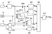
- FIG. 3 is a control block diagram illustrating a control configuration of the power steering apparatus according to the first embodiment.
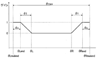
- 3 is a gain map used in stroke end control according to the first embodiment.
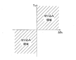
- 3 is a cut determination map according to the first embodiment.
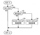
- 3 is a flowchart illustrating a stroke end control process according to the first embodiment.
- 6 is a flowchart illustrating stroke end control processing according to the second embodiment.
- 10 is a flowchart illustrating stroke end control processing according to the third embodiment.
- FIG. 9 is a gain map used in the stroke end control according to the third embodiment.
- 10 is a flowchart illustrating stroke end control processing according to a fourth embodiment.
- FIG. 9 is a gain map used in the stroke end control according to the third embodiment.
- 10 is a characteristic diagram illustrating a relationship between a target rudder angle and a boundary rudder angle according to a fifth embodiment. It is the schematic showing the relationship between the driving
- FIG. 1 is a schematic system diagram illustrating a power steering apparatus according to the first embodiment.
- a steering shaft 2 is connected to the steering wheel 1.
- a pinion shaft 2b is connected to the end of the steering shaft 2 opposite to the steering wheel 1 via a torsion bar 11a.
- the pinion shaft 2b has a pinion 2a.
- a rack and pinion mechanism 3 in which the pinion 2a and the rack teeth 4a mesh with each other is provided at a connection portion between the pinion 2a and the rack housing portion 40 that accommodates the rack bar 4.
- the rack housing portion 40 includes a power steering mechanism 5 that assists the axial force of the rack bar 4.
- the power steering mechanism 5 includes an electric motor 5 a and a gear mechanism 5 b that converts the torque of the electric motor 5 a into an axial force and applies an assist force to the rack bar 4.
- the steering shaft 2 has a steering angle sensor 10 that detects a turning angle ⁇ that is a steering wheel steering operation amount of the driver. Between the steering shaft 2 and the pinion shaft 2b, there is a torque sensor 11 that detects the steering torque of the driver based on the amount of twist of the torsion bar 11a.
- the electric motor 5a has a motor rotation angle sensor 13 that detects the rotation angle of the electric motor 5a. Moreover, it has the vehicle speed sensor 12 which detects vehicle speed VSP.
- the control device 20 includes a receiving unit that receives signals from the steering angle sensor 10, the torque sensor 11, the vehicle speed sensor 12, and the motor rotation angle sensor 13. The control device 20 controls the current of the electric motor 5a based on various signals, and applies an optimal assist force.
- FIG. 2 is a control block diagram showing the control configuration of the power steering apparatus of the first embodiment.
- the torque calculation unit 201 calculates the driver's steering torque Ts based on the detection signal of the torque sensor 11.
- the assist calculation unit 202 calculates a reference assist torque Tas based on the steering torque Ts and outputs the calculated assist torque Tas to the addition unit 209.
- the phase compensation calculation unit 203 calculates a phase compensation torque Tx that compensates for a phase difference generated by the low-rigidity torsion bar 11 a built in the torque sensor 11 and suppresses vibration of the system, and outputs it to the addition unit 209.
- the steering angle calculation unit 204 calculates the turning angle ⁇ s of the steered wheels 30 based on the detection signal of the steering angle sensor 10.
- the steering speed calculation unit 205 calculates the steering speed ⁇ s of the steering wheel 1 based on the detection signal of the steering angle sensor 10.
- the damping torque calculation unit 206 calculates a damping torque Td that gives a viscous resistance that improves the convergence and stability of the vehicle based on the steering speed ⁇ s, and outputs it to the addition unit 209.
- the software rack stopper setting unit 207 receives the steering torque Ts, the vehicle speed VSP, and the turning angle ⁇ s, the signal receiving unit 2071, the stroke end setting unit 207a that sets the physical stroke end, and the set stroke end A stroke end signal receiving unit 2072.
- the stroke end setting unit 207a has a reference value information storage unit that stores a stroke end reference value ⁇ realend_default corresponding to a preset physical stroke end.
- the software rack stopper setting unit 207 calculates a right software rack stopper ⁇ Rend and a left software rack stopper ⁇ Lend, which are stroke ends in control, based on the steering torque Ts, the vehicle speed VSP, and the turning angle ⁇ s.
- Both the right software rack stopper ⁇ Rend and the left software rack stopper ⁇ Lend are collectively referred to as software rack stopper ⁇ end, and both the right stroke end ⁇ Rrealend and left stroke end ⁇ Lrealend are collectively referred to as stroke end ⁇ realend. .
- the stroke end control unit 208 calculates the stopper torque Tend based on the software rack stopper ⁇ end, the vehicle speed VSP, the turning angle ⁇ s, and the steering torque Ts. Then, the stopper torque Tend is output to an assist canceling unit 208a and an adding unit 209, which will be described later. Specifically, a value obtained by multiplying the steering torque Ts by a gain and inverting the sign is output as Tend.
- FIG. 3 is a gain map used in the stroke end control of the first embodiment.
- a steering angle ⁇ is set on the horizontal axis, and a gain is set on the vertical axis.
- a right software rack stopper ⁇ Rend that is offset from the right stroke end ⁇ Rrealend to the left software rack stopper ⁇ Lend by a predetermined deviation angle ⁇ x is set.
- a right control start value ⁇ R that is offset from the right software rack stopper ⁇ Rend to the left software rack stopper ⁇ Lend side by a predetermined amount ⁇ 1 is set.
- a left software rack stopper ⁇ Lend offset from the left stroke end ⁇ Lrealend to the right software rack stopper ⁇ Rend side by a predetermined deviation angle ⁇ x is set on the horizontal axis.
- a left control start value ⁇ L that is offset from the left software rack stopper ⁇ Lend by a predetermined amount ⁇ 1 to the right software rack stopper ⁇ Rend is set.
- the right control start value ⁇ R and the left control start value ⁇ L are collectively referred to as a control start value ⁇ st.
- the neutral position of the turning angle ⁇ exists between ⁇ L and ⁇ R. Within this range, the gain is set to 0 and no particular control is performed. On the other hand, when the turning angle ⁇ exceeds ⁇ R and approaches ⁇ Rend, the gain gradually increases toward 1. Similarly, when the turning angle ⁇ exceeds ⁇ L and approaches ⁇ Lend, the gain gradually increases toward 1. When a large gain is output, the stopper torque Tend is output as a negative value having a large absolute value, and the final assist torque becomes small. Therefore, when the gain is 1, torque that cancels the steering torque Ts is output from the electric motor 5a. As a result, the assist torque is reduced from the control start position ⁇ st toward the software rack stopper ⁇ end, while the assist torque is increased from the software rack stopper ⁇ end toward the control start position ⁇ st so as to become a normal assist torque.
- the assist canceling unit 208a adds the stopper torque Tend. That is, when the stroke end control is started, Tend is output by multiplying the steering torque Ts by the gain and inverting the sign. Then, since the stopper torque Tend acts to cancel the steering torque Ts, for example, when the gain is 1, the steering torque Ts is not input to the assist calculation unit 202 or the phase compensation calculation unit 203. Therefore, the assist torque Tas and the phase compensation torque Tx are not output, and unnecessary assist can be prevented. On the other hand, the stopper torque Tend is also output to the adding unit 209.
- the stopper torque Tend acts as a torque that cancels the steering torque generated by the driver's muscle strength (hereinafter referred to as manual torque Tman), so that the turning angle ⁇ s is reduced while suppressing the uncomfortable feeling given to the driver.
- the software rack stopper ⁇ end can be controlled so as not to exceed.
- the motor torque command calculation unit 210 determines a current value to be commanded to the electric motor 5a based on the assist torque T finally calculated from various torque commands, and outputs it to the electric motor 5a.
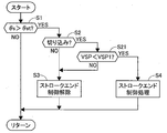
- FIG. 5 is a flowchart showing the stroke end control process of the first embodiment.
- step S1 it is determined whether or not the turning angle ⁇ s exceeds the control start value ⁇ st. If it exceeds, the process proceeds to step S2, and otherwise, the control flow ends.
- step S2 it is determined whether or not it is in the cut state. If it is in the cut state, the process proceeds to step S4. Otherwise, the process proceeds to step S3.
- FIG. 4 is a cut determination map according to the first embodiment. In the map in which the horizontal axis represents the steering speed ⁇ s and the vertical axis represents the steering torque Ts, if the steering speed ⁇ s and the steering torque Ts are both positive or negative, it is determined that the cutting state is present.
- step S3 the stroke end control is canceled.
- step S4 a stroke end control process is executed. Specifically, the steering torque Ts used for the calculation of the assist torque or the like is canceled, and a reaction force torque corresponding to the steering torque Ts is applied by the electric motor 5a. Thereby, it is possible to cancel the manual torque Tman without applying unnecessary assist torque Tas or the like.
- a power steering apparatus including a rack and pinion mechanism 3 (steering mechanism) that steers the steered wheels 30 in accordance with a steering operation of the steering wheel 1, and an electric motor 5a that applies a steering force to the rack and pinion mechanism 3.
- a signal receiving unit 2071 (steering angle signal receiving unit) that receives a steering angle signal that is a signal indicating the steering angle ⁇ s of the steered wheels 30 and the steering torque Ts of the rack and pinion mechanism 3.
- a signal receiving unit 2071 (steering torque signal receiving unit) that receives a steering torque signal that is a signal, and an angle set in a range from one stroke end to the other stroke end of the turning angle ⁇ s.
- a software rack stopper setting unit 207 (stopper angle setting unit) for setting a software rack stopper ⁇ end (stopper angle) and a steering operation of the steering wheel 1
- a stroke end control unit 208 that calculates a stopper torque Tend that is a steering force in a direction opposite to the direction in which the steering angle ⁇ s approaches the software rack stopper ⁇ end based on the steering torque Ts
- a stopper torque calculation unit and a motor torque command calculation unit 210 (motor command signal calculation unit) that calculates a motor command signal for driving the electric motor 5a based on the driving state of the vehicle and the stopper torque Tend.
- the signal receiving unit 2071 may receive the steering angle information directly from the steering angle sensor 10, or may estimate the steering angle from the motor rotation angle signal by calculation. Further, the signal receiving unit 2071 may be a part where the control device 20 receives a steering torque signal from the torque sensor 11, or may be a part which receives the steering torque signal within the control device 20.
- the software rack stopper setting unit 207 may set a stopper angle during operation, or may be a memory that stores a predetermined angle.
- the software rack stopper setting unit 207 sets a position offset by a predetermined deviation angle ⁇ x from the stroke end ⁇ realend on one side to the stroke end direction on the other side as the software rack stopper ⁇ end on one side, and sets the stroke end on the other side A position offset from ⁇ realend by a predetermined deviation angle ⁇ x in the stroke end direction on one side is set as the software rack stopper ⁇ end on the other side. Therefore, the impact at the stroke end can be suppressed by applying the steering force in the direction to suppress the steering operation near the stroke end to the steering operation in the stroke end direction.
- the stroke end control unit 208 includes a gain correction unit that corrects the stopper torque Tend with a gain.
- the gain increases as the steering angle ⁇ s approaches the stroke end ⁇ realend on one side or the other side. It is set to be large. Therefore, by gradually increasing the stopper torque Tend as it approaches the stroke end ⁇ realend, the uncomfortable feeling of steering can be suppressed.
- the gain is set to be 1 when the turning angle ⁇ s is the software rack stopper ⁇ end on one side or the software rack stopper ⁇ end on the other side. Therefore, by applying the stopper torque Tend so as to balance the steering force at the time of the software rack stopper ⁇ end, further cutting operation is performed, and the occurrence of an impact at the stroke end ⁇ realend can be suppressed.
- FIG. 6 is a flowchart illustrating a stroke end control process according to the second embodiment.
- step S21 it is determined whether or not the vehicle speed VSP is less than the predetermined vehicle speed VSP1, and when the vehicle speed VSP is less than the predetermined vehicle speed VSP1, the process proceeds to step S4 and the stroke end control process is performed. Advances to step S3 to cancel the stroke end control process.
- the predetermined vehicle speed VSP1 is a vehicle speed associated with a garage entry operation or the like in a parking lot, and is a vehicle speed that does not significantly affect the vehicle behavior even if the steering operation is temporarily suppressed.
- the stroke end control process based on the stopper torque Tend is not performed. Therefore, when the vehicle speed is equal to or higher than the predetermined vehicle speed VSP1, it is possible to avoid that the steering operation is suppressed due to the abnormality of the device even though the turning angle ⁇ s is not near the stroke end.
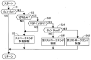
- FIG. 7 is a flowchart illustrating the stroke end control process according to the third embodiment.
- step S22 it is determined whether or not the turning angle ⁇ s is larger than the software rack stopper ⁇ end.
- the process proceeds to step S41, and the first stroke end control is performed.
- step S4 in the first and second embodiments the stroke end control is performed.
- the process proceeds to step S42 and the second stroke end control is performed.
- FIG. 8 is a gain map used in the third embodiment stroke end control.
- the gain was fixed to 1 when the turning angle ⁇ s was larger than the software rack stopper ⁇ end.
- a gradient larger than the gain gradient used in the first stroke end control is set, and a gain larger than 1 is set.
- Gain is greater than 1 when the turning angle ⁇ s is closer to the stroke end ⁇ realend on one side than the software rack stopper ⁇ end on one side, or closer to the stroke end ⁇ realend on the other side than the software rack stopper ⁇ end on the other side. It is set to be large. Therefore, it is possible to suppress the occurrence of an impact at the stroke end ⁇ realend. Further, when the cutting operation is further performed in a state where the stroke end ⁇ realend has been reached, the detection range of the torque sensor 11 may be exceeded, and there is a possibility that the stopper torque corresponding to the steering torque signal cannot be appropriately calculated.
- the gain is set to increase as the turning angle ⁇ s approaches the one side stroke end ⁇ realend.
- the turning angle ⁇ s is set so as to increase as it approaches the stroke end ⁇ realend on the other side. Therefore, the turning angle ⁇ s can be more positively returned to the software rack stopper ⁇ end side.
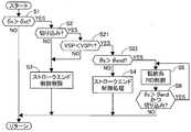
- FIG. 9 is a flowchart illustrating the stroke end control process according to the fourth embodiment.
- Example 3 when the turning angle ⁇ s is larger than the software rack stopper ⁇ end, a gain larger than 1 is set.
- the fourth embodiment when the turning angle ⁇ s is larger than the software rack stopper ⁇ end, the software rack stopper ⁇ end is set as the target steering angle, and the PID control is performed so that the turning angle ⁇ s becomes the target steering angle. Is what you do.
- step S5 steer angle PID control is performed.
- PID control refers to the stopper torque Tend (pid) based on the following relational expression using the proportional gain Kp, integral gain Ki, and differential gain Kd for the deviation ⁇ between the target rudder angle and the turning angle ⁇ s. Is calculated.
- Tend (PID) Kp ⁇ ⁇ + Ki ⁇ ( ⁇ dt) + Kd ⁇ (d ( ⁇ ) / dt)
- step S6 it is determined whether the turning angle ⁇ s is larger than the software rack stopper ⁇ end and whether or not the cutting is in progress. If both conditions are satisfied, step S5 is repeated, and if either condition is not satisfied, the stroke end control is canceled.
- Example 4 the following operational effects can be obtained. (7)
- the stroke end control unit 208 moves the electric motor 5a in the direction to return to the software rack stopper ⁇ end side on one side.
- the stopper torque Tend is calculated so as to generate torque and the turning angle ⁇ s is closer to the other side stroke end ⁇ realend than the other side software rack stopper ⁇ end
- the electric motor 5a moves to the other side software rack stopper ⁇ end side. Stopper torque Tend is calculated to generate torque in the return direction. Therefore, the turning angle ⁇ s can be more positively returned to the software rack stopper ⁇ end side.
- Example 5 Next, Example 5 will be described.
- the target rudder angle is set to the software rack stopper ⁇ end.
- the present invention is applied to LDP control (Lane Departue Prevention Control) that allows the vehicle to travel while traveling in the travel lane while maintaining the lane.
- FIG. 10 is a characteristic diagram showing the relationship between the target rudder angle and the boundary rudder angle in the fifth embodiment
- FIG. 11 is a schematic diagram showing the relationship between the travel lane and the host vehicle in the fifth embodiment. As shown in FIG.
- the target lane width is set within the lane width, and the target rudder angle is calculated so that the vehicle travels within the target lane width.
- the turning angle ⁇ s is controlled to be the target steering angle. Specifically, the steering angle when traveling along the target lane in the center of the target lane width is set as the target steering angle.
- the value obtained by adding the predetermined amount ⁇ from the target rudder angle is used as the right boundary rudder angle corresponding to the right software rack stopper ⁇ Rend, and the value obtained by subtracting the predetermined amount ⁇ from the target rudder angle is equivalent to the left software rack stopper ⁇ Lend.
- the stopper torque Tend obtained by multiplying the steering torque Ts by the gain is calculated, and the steering angle ⁇ s is calculated as the target steering angle Ts. Control to be corners. Hereinafter, this control is referred to as rack stroke control.
- FIG. 12 is a flowchart showing rack stroke control according to the fifth embodiment.
- step S101 it is determined whether or not the turning angle ⁇ s matches the control start value ⁇ st that is the target steering angle. If they match, the process proceeds to step S102 to cancel the rack stroke control. On the other hand, if they do not match, the process proceeds to step S103.
- step S103 it is determined whether or not it is in the cutting state. If it is in the cutting state, the process proceeds to step S104. In other cases, the process proceeds to step S102 and the rack stroke control is canceled.
- step S104 it is determined whether or not the steering torque Ts is equal to or greater than the predetermined torque Ts1, and if it is equal to or greater than the predetermined torque Ts1, the process proceeds to step S105, and if it is less than the predetermined torque Ts1, the process proceeds to step S102 and the rack stroke control is released.
- the predetermined torque Ts1 represents a case where the driver generates the steering torque Ts to some extent beyond the range of play set for the steering wheel 1. For example, intervention by LDP control is performed for a situation in which a large steering torque Ts is unexpectedly input while the vehicle is slowly steered, and the vehicle deviates from the traveling lane.
- step S105 rack stroke control is performed.
- the rack stroke control is the same control as the stroke end control, and is controlled by setting the target rudder angle to ⁇ st and setting the boundary rudder angle to the software rack stopper ⁇ end.
- PID control is performed instead of gain control, and the electric motor 5a is actuated more positively within the range of the boundary rudder angle ⁇ end. May be.
- step S106 it is determined whether the steered angle ⁇ s does not match the target steered angle ⁇ st, and whether or not the vehicle is in the cut state. If both conditions are satisfied, step S105 is repeated, and either condition is not satisfied. When the rack stroke control is canceled. This makes it possible to stably control the turning angle ⁇ s along the traveling lane.
- Example 4 when controlling not only to LDP control but to become a target steering angle in automatic driving control, the input of the steering torque Ts from a driver
- the target rudder angle is set as ⁇ st.
- the boundary rudder angle is set to ⁇ st and the boundary rudder angle is exceeded, the steering torque Ts may be canceled by the gain.
- the present invention is applied to cancel the steering torque Ts in order to avoid unexpected steering caused by a driver's steering error. You may make it do.
- the control device for the power steering device is a control device for a power steering device comprising: a steering mechanism for steering the steered wheels in accordance with a steering operation of the steering wheel; and an electric motor for applying a steering force to the steering mechanism,
- a steering angle signal receiving unit that receives a steering angle signal that is a signal indicating the steering angle of the steered wheel
- a steering torque signal receiving unit that receives a steering torque signal that is a signal indicating the steering torque of the steering mechanism
- a stopper angle setting unit that sets a stopper angle that is an angle set in a range from the stroke end on one side to the stroke end on the other side, and the steering according to the steering operation of the steering wheel
- a stopper torque which is a steering force in a direction opposite to the direction in which the turning angle approaches the stopper angle, is applied to the steering torque.
- the stopper angle setting unit sets a position offset by a predetermined amount from the stroke end on the one side in the stroke end direction on the other side as a stopper angle on one side, A position offset by a predetermined amount from the stroke end toward the stroke end on the one side is set as the stopper angle on the other side.
- the stopper torque calculation unit includes a gain correction unit that corrects the stopper torque by a gain, and the gain has a turning angle on one side or the other side.
- the stopper torque is set to increase as it approaches the stroke end.
- the gain is set to be 1 when the turning angle is the one-side stopper angle or the other-side stopper angle.
- the gain is obtained when the turning angle is closer to the stroke end on the one side than the stopper angle on the one side, or on the other side than the stopper angle on the other side. It is set to be larger than 1 when close to the stroke end on the side.
- the gain may be adjusted so that the turning angle is closer to the one side when the turning angle is closer to the stroke end on the one side than the stopper angle on the one side. It is set so as to increase as it approaches the stroke end, and when the turning angle is closer to the stroke end on the other side than the stopper angle on the other side, the steering angle increases as it approaches the stroke end on the other side. It is set to be.
- the stopper torque calculation unit is configured such that the electric motor is the one when the turning angle is closer to the stroke end on the one side than the stopper angle on the one side.
- the stopper torque is calculated so as to generate torque in a direction to return to the stopper angle side, and when the turning angle is closer to the stroke end on the other side than the stopper angle on the other side, the electric motor The stopper torque is calculated so as to generate torque in a direction returning to the stopper angle side on the other side.
- the motor command signal calculation unit does not calculate the motor command signal based on the stopper torque when the vehicle speed is equal to or higher than a predetermined vehicle speed.
- control device of the power steering apparatus includes a target turning angle receiving unit that receives a signal of a target turning angle that is a target angle of the turning angle, and the stopper The angle setting unit sets the target turning angle as the stopper angle.
- the stopper torque calculation unit includes a gain correction unit that corrects the stopper torque by a gain, and the gain is such that the turning angle approaches the stopper angle. The stopper torque is set so as to increase.
Landscapes
- Engineering & Computer Science (AREA)
- Chemical & Material Sciences (AREA)
- Combustion & Propulsion (AREA)
- Transportation (AREA)
- Mechanical Engineering (AREA)
- Physics & Mathematics (AREA)
- General Physics & Mathematics (AREA)
- Steering Control In Accordance With Driving Conditions (AREA)
- Power Steering Mechanism (AREA)
Abstract
ストロークエンド付近で安定した操舵感を得ることが可能なパワーステアリング装置の制御装置を提供すること。 パワーステアリング装置の制御装置は、ステアリングホイールの操舵操作に伴い転舵角がストッパ角に近づくとき、転舵角がストッパ角に近づく方向とは逆方向の操舵力であるストッパトルクを操舵トルク信号に基づき演算し、車両の運転状態およびストッパトルクに基づき電動モータを駆動するモータ指令信号を演算する。
Description
本発明は、ステアリングホイールの操舵力をアシストするパワーステアリング装置の制御装置に関する。
従来、特許文献1に記載の技術では、パワーステアリング装置において、機械的な最大操舵位置(以下、ストロークエンドと記載する。)まで操舵し、急激に操舵が止められることによる衝撃等を抑制するために、ストロークエンドに向けてアシストトルクを低減している。
特許文献1では舵角速度や車速からアシストトルク制御量を演算するため、制御中の操舵感に違和感を生じやすいという問題があった。 本発明は、上記課題に鑑みてなされたものであり、ストロークエンド付近で安定した操舵感を得ることが可能なパワーステアリング装置の制御装置を提供することを目的とする。
本発明の一実施形態によるパワーステアリング装置の制御装置は、ステアリングホイールの操舵操作に伴い転舵角がストッパ角に近づくとき、転舵角がストッパ角に近づく方向とは逆方向の操舵力であるストッパトルクを操舵トルク信号に基づき演算し、車両の運転状態およびストッパトルクに基づき電動モータを駆動するモータ指令信号を演算する。
すなわち、ストッパ角に近づく操舵操作を抑制するストッパトルクを、操舵操作のトルクである操舵トルクに基づいて演算するため、適切なストッパトルクを付与することができ、操舵フィーリングを向上できる。
〔実施例1〕
図1は実施例1のパワーステアリング装置を表す概略システム図である。ステアリングホイール1には、ステアリングシャフト2が接続されている。ステアリングシャフト2のステアリングホイール1と反対側の端部にはトーションバー11aを介してピニオンシャフト2bが接続されている。ピニオンシャフト2bは、ピニオン2aを有する。ピニオン2aとラックバー4を収容するラック収装部40との接続部位には、ピニオン2aとラック歯4aとが噛合うラック&ピニオン機構3を有する。これにより、ステアリングホイール1の回転方向運動を軸方向運動に変換し、転舵輪30を転舵する。ラック収装部40には、ラックバー4の軸力をアシストするパワーステアリング機構5を有する。パワーステアリング機構5は、電動モータ5aと、電動モータ5aのトルクを軸力に変換してラックバー4にアシスト力を付与するギヤ機構5bとを有する。
図1は実施例1のパワーステアリング装置を表す概略システム図である。ステアリングホイール1には、ステアリングシャフト2が接続されている。ステアリングシャフト2のステアリングホイール1と反対側の端部にはトーションバー11aを介してピニオンシャフト2bが接続されている。ピニオンシャフト2bは、ピニオン2aを有する。ピニオン2aとラックバー4を収容するラック収装部40との接続部位には、ピニオン2aとラック歯4aとが噛合うラック&ピニオン機構3を有する。これにより、ステアリングホイール1の回転方向運動を軸方向運動に変換し、転舵輪30を転舵する。ラック収装部40には、ラックバー4の軸力をアシストするパワーステアリング機構5を有する。パワーステアリング機構5は、電動モータ5aと、電動モータ5aのトルクを軸力に変換してラックバー4にアシスト力を付与するギヤ機構5bとを有する。
ステアリングシャフト2上には、運転者のステアリングホイール操舵操作量である転舵角θを検出する操舵角センサ10を有する。ステアリングシャフト2とピニオンシャフト2bとの間には、トーションバー11aの捩れ量に基づいて運転者の操舵トルクを検出するトルクセンサ11を有する。電動モータ5aには、電動モータ5aの回転角を検出するモータ回転角センサ13を有する。また、車速VSPを検出する車速センサ12を有する。制御装置20は、操舵角センサ10、トルクセンサ11、車速センサ12、モータ回転角センサ13からの信号を受信する受信部を有する。制御装置20は、各種信号に基づいて電動モータ5aの電流を制御し、最適なアシスト力を付与する。
図2は実施例1のパワーステアリング装置の制御構成を表す制御ブロック図である。 トルク演算部201では、トルクセンサ11の検出信号に基づいて運転者の操舵トルクTsを演算する。アシスト演算部202では、操舵トルクTsに基づいて基準となるアシストトルクTasを演算し、加算部209に出力する。位相補償演算部203では、トルクセンサ11に内蔵される低剛性のトーションバー11aにより生じる位相差を補償し、システムの振動を抑制する位相補償トルクTxを演算し、加算部209に出力する。操舵角演算部204では、操舵角センサ10の検出信号に基づいて転舵輪30の転舵角θsを演算する。操舵速度演算部205では、操舵角センサ10の検出信号に基づいてステアリングホイール1の操舵速度Δθsを演算する。ダンピングトルク演算部206では、操舵速度Δθsに基づいて車両の収斂性及び安定性を向上する粘性抵抗を付与するダンピングトルクTdを演算し、加算部209に出力する。
ソフトウェアラックストッパ設定部207は、操舵トルクTs、車速VSP及び転舵角θsを受信する信号受信部2071と、物理的なストロークエンドを設定するストロークエンド設定部207aと、設定されたストロークエンドを受信するストロークエンド信号受信部2072と、を有する。ストロークエンド設定部207aは、予め設定された物理的なストロークエンドに相当するストロークエンド基準値θrealend_defaultを記憶する基準値情報記憶部を有する。ソフトウェアラックストッパ設定部207は、操舵トルクTsと、車速VSPと、転舵角θsとに基づいて制御上のストロークエンドである右側ソフトウェアラックストッパθRendと、左側ソフトウェアラックストッパθLendとを演算する。尚、右側ソフトウェアラックストッパθRendと左側ソフトウェアラックストッパθLendの両方を、総称してソフトウェアラックストッパθendとも記載し、右側ストロークエンドθRrealendと左側ストロークエンドθLrealendの両方を、総称してストロークエンドθrealendとも記載する。
ストロークエンド制御部208は、ソフトウェアラックストッパθendと、車速VSPと、転舵角θsと、操舵トルクTsに基づいて、ストッパトルクTendを演算する。そして、ストッパトルクTendを、後述するアシスト相殺部208aと、加算部209に出力する。具体的には、操舵トルクTsにゲインを乗算し、符号を反転した値をTendとして出力する。
図3は実施例1のストロークエンド制御において使用するゲインマップである。横軸には転舵角θが設定され、縦軸にゲインが設定されている。横軸には、右側ストロークエンドθRrealendから所定乖離角θxだけ左側ソフトウェアラックストッパθLend側にオフセットした右側ソフトウェアラックストッパθRendが設定されている。更に、右側ソフトウェアラックストッパθRendから所定量θ1だけ左側ソフトウェアラックストッパθLend側にオフセットした右側制御開始値θRが設定されている。同様に、横軸には、左側ストロークエンドθLrealendから所定乖離角θxだけ右側ソフトウェアラックストッパθRend側にオフセットした左側ソフトウェアラックストッパθLendが設定されている。更に、左側ソフトウェアラックストッパθLendから所定量θ1だけ右側ソフトウェアラックストッパθRendにオフセットした左側制御開始値θLが設定されている。以下、右側制御開始値θR及び左側制御開始値θLを総称して制御開始値θstとも記載する。
転舵角θの中立位置は、θLとθRとの間に存在し、この範囲内ではゲインを0として特に制御は行わない。一方、転舵角θがθRを超えてθRendに近づくと、ゲインが1に向けて徐々に大きくなる。同様に、転舵角θがθLを超えてθLendに近づくと、ゲインが1に向けて徐々に大きくなる。大きなゲインが出力されると、ストッパトルクTendは、絶対値が大きな負値として出力され、最終的なアシストトルクが小さくなる。よって、ゲインが1のときは、操舵トルクTsを打ち消すトルクが電動モータ5aから出力される。これにより、制御開始位置θstからソフトウェアラックストッパθendに向けてアシストトルクを低減する一方、ソフトウェアラックストッパθendから制御開始位置θstに向けてアシストトルクを通常のアシストトルクとなるように増大させる。
アシスト相殺部208aでは、ストッパトルクTendを加算する。すなわち、ストロークエンド制御が開始されると、操舵トルクTsにゲインを乗算し、符号を反転したTendが出力される。すると、ストッパトルクTendは、操舵トルクTsを打ち消すように作用するため、例えばゲインが1の場合、アシスト演算部202や位相補償演算部203に操舵トルクTsが入力されることはない。よって、アシストトルクTasや位相補償トルクTxが出力されることがなく、不要なアシストを防止できる。一方、加算部209にも、ストッパトルクTendが出力される。これにより、ストッパトルクTendは、運転者の筋力によって生じる操舵トルク(以下、マニュアルトルクTmanと記載する。)を打ち消すトルクとして作用するため、運転者に与える違和感を抑制しつつ、転舵角θsが、ソフトウェアラックストッパθendを越えないように制御できる。
モータトルク指令演算部210では、各種トルク指令から最終的に演算されたアシストトルクTに基づいて、電動モータ5aに指令する電流値を決定し、電動モータ5aに出力する。
図5は、実施例1のストロークエンド制御処理を表すフローチャートである。 ステップS1では、転舵角θsが制御開始値θstを越えたか否かを判断し、越えた場合はステップS2に進み、それ以外の場合は本制御フローを終了する。 ステップS2では、切り込み状態か否かを判断し、切り込み状態のときはステップS4に進み、それ以外の場合はステップS3に進む。図4は、実施例1の切り込み判断マップである。横軸に操舵速度Δθsを取り、縦軸に操舵トルクTsを取ったマップのうち、操舵速度Δθs及び操舵トルクTsが共に正の領域、もしくは共に負の領域では、切り込み状態と判断する。 ステップS3では、ストロークエンド制御を解除する。これにより、ストロークエンドrealendから離間する操作が行われたときは、速やかに通常のアシスト制御が実行されるため、運転者に違和感を与えることがない。 ステップS4では、ストロークエンド制御処理を実行する。具体的には、アシストトルク等の演算に使用する操舵トルクTsを相殺するとともに、操舵トルクTsに応じた反力トルクを電動モータ5aにより付与する。これにより、不要なアシストトルクTas等を与えず、かつ、マニュアルトルクTmanを打ち消すことができる。
〔実施例1の効果〕
以下、実施例1にあっては、下記の作用効果が得られる。
(1)ステアリングホイール1の操舵操作に伴い転舵輪30を操舵させるラック&ピニオン機構3(操舵機構)と、ラック&ピニオン機構3に操舵力を付与する電動モータ5aと、を備えたパワーステアリング装置の制御装置であって、転舵輪30の転舵角θsを示す信号である舵角信号を受信する信号受信部2071(舵角信号受信部)と、ラック&ピニオン機構3の操舵トルクTsを示す信号である操舵トルク信号を受信する信号受信部2071(操舵トルク信号受信部)と、転舵角θsのうち、一方側のストロークエンドから他方側のストロークエンドの範囲の中に設定された角度であるソフトウェアラックストッパθend(ストッパ角)を設定するソフトウェアラックストッパ設定部207(ストッパ角設定部)と、ステアリングホイール1の操舵操作に伴い転舵角θsがソフトウェアラックストッパθendに近づくとき、転舵角θsがソフトウェアラックストッパθendに近づく方向とは逆方向の操舵力であるストッパトルクTendを操舵トルクTsに基づき演算するストロークエンド制御部208(ストッパトルク演算部)と、車両の運転状態およびストッパトルクTendに基づき電動モータ5aを駆動するモータ指令信号を演算するモータトルク指令演算部210(モータ指令信号演算部)と、を有する。 よって、ソフトウェアラックストッパθendに近づく操舵操作を抑制するストッパトルクTendを、操舵操作のトルクである操舵トルクTsに基づき演算するため、適切なストッパトルクTendを付与することができ、操舵フィーリングを向上させることができる。 尚、信号受信部2071は、操舵角センサ10から直接舵角情報を受信するものであってもよいし、モータ回転角信号から舵角を演算で推定するものであってもよい。また、信号受信部2071は、制御装置20がトルクセンサ11から操舵トルク信号を受信する部分であってもよいし、制御装置20内で操舵トルク信号を受信する部分であってもよい。また、ソフトウェアラックストッパ設定部207は、運転中にストッパ角を設定するものであってもよいし、所定角を記憶するメモリ等であってもよい。
(2)ソフトウェアラックストッパ設定部207は、一方側のストロークエンドθrealendから他方側のストロークエンド方向へ所定乖離角θxだけオフセットした位置を一方側のソフトウェアラックストッパθendとして設定し、他方側のストロークエンドθrealendから一方側のストロークエンド方向へ所定乖離角θxだけオフセットした位置を他方側のソフトウェアラックストッパθendとして設定する。 よって、ストロークエンド方向への操舵操作に対し、ストロークエンド付近で操舵操作を抑制する方向の操舵力を付与することにより、ストロークエンドにおける衝撃を抑制することができる。
(3)ストロークエンド制御部208は、ゲインによりストッパトルクTendを補正するゲイン補正部を有し、ゲインは、転舵角θsが一方側または他方側のストロークエンドθrealendに近づくほど、ストッパトルクTendが大きくなるように設定されている。 よって、ストロークエンドθrealendに近づくほど徐々にストッパトルクTendを増大させることで、操舵違和感を抑制することができる。
(4)ゲインは、転舵角θsが一方側のソフトウェアラックストッパθendまたは他方側のソフトウェアラックストッパθendのとき、1となるように設定されている。 よって、ソフトウェアラックストッパθendのとき、操舵力と釣り合うようにストッパトルクTendを付与することで、更に切り込み操作が行われ、ストロークエンドθrealendで衝撃が発生することを抑制することができる。
〔実施例2〕 次に、実施例2について説明する。基本的な構成は実施例1と同じであるため、異なる点についてのみ説明する。図6は、実施例2のストロークエンド制御処理を表すフローチャートである。実施例2では、ステップS21において、車速VSPが所定車速VSP1未満か否かを判断し、所定車速VSP1未満のときは、ステップS4に進んでストロークエンド制御処理を実施し、所定車速VSP1以上のときは、ステップS3に進んでストロークエンド制御処理を解除する。ここで、所定車速VSP1は、駐車場での車庫入れ操作等に伴う車速であり、仮に操舵操作を抑制したとしても車両挙動に大きな影響を与えない程度の車速である。言い換えると、車速VSPが所定車速VSP1以上のときは、ストッパトルクTendに基づくストロークエンド制御処理を行わない。よって、所定車速VSP1以上のとき、装置の異常により、転舵角θsがストロークエンド付近ではないにも関わらず操舵操作が抑制されるとことを回避できる。
〔実施例3〕 次に、実施例3について説明する。基本的な構成は実施例2と同じであるため、異なる点についてのみ説明する。図7は、実施例3のストロークエンド制御処理を表すフローチャートである。実施例3では、ステップS22において、転舵角θsがソフトウェアラックストッパθendより大きいか否かを判断し、転舵角θsがソフトウェアラックストッパθend以下のときはステップS41に進み、第1ストロークエンド制御として、実施例1,2のステップS4と同様のストロークエンド制御を実施する。一方、転舵角θsがソフトウェアラックストッパθendより大きいときは、ステップS42に進んで、第2ストロークエンド制御を実施する。図8は、実施例3ストロークエンド制御において使用するゲインマップである。実施例1,2では、転舵角θsがソフトウェアラックストッパθendより大きいときは、ゲインを1に固定していた。これに対し、実施例3の第2ストロークエンド制御では、第1ストロークエンド制御で使用するゲインの勾配よりも大きな勾配が設定され、かつ、1より大きなゲインが設定されている。
よって、ソフトウェアラックストッパθendからストロークエンドθrealendに向けて、運転者が更にステアリングホイール1を切り込むと、更に大きなゲインが設定され、ソフトウェアラックストッパθendに向けてステアリングホイール1を戻すようなトルクが電動モータ5aにより付与される。
以上説明したように、実施例3にあっては、下記の作用効果が得られる。
(5)ゲインは、転舵角θsが一方側のソフトウェアラックストッパθendより一方側のストロークエンドθrealendに近いとき、または他方側のソフトウェアラックストッパθendより他方側のストロークエンドθrealendに近いとき、1より大きくなるように設定されている。 よって、ストロークエンドθrealendでの衝撃の発生を抑制することができる。また、ストロークエンドθrealendに到達した状態で、更に切り込み操作されるとき、トルクセンサ11の検出範囲を超えてしまい、操舵トルク信号に応じたストッパトルクが適切に演算できなくなる虞があるが、この状態において、ゲインを1より大きく設定しておくことにより、過大な操舵トルクに対して適切なストッパトルクを付与することができる。
(6)ゲインは、転舵角θsが一方側のソフトウェアラックストッパθendよりも一方側のストロークエンドθrealendに近いとき、転舵角θsが一方側のストロークエンドθrealendに近づくほど大きくなるように設定され、転舵角θsが他方側のソフトウェアラックストッパθendよりも他方側のストロークエンドθrealendに近いとき、転舵角θsが他方側のストロークエンドθrealendに近づくほど大きくなるように設定されている。 よって、転舵角θsをより積極的にソフトウェアラックストッパθend側へ戻すことができる。
〔実施例4〕次に、実施例4について説明する。基本的な構成は実施例3と同じであるため、異なる点についてのみ説明する。図9は、実施例4のストロークエンド制御処理を表すフローチャートである。実施例3では、転舵角θsがソフトウェアラックストッパθendより大きいときは、1より大きなゲインを設定した。これに対し、実施例4では、転舵角θsがソフトウェアラックストッパθendより大きいときは、目標舵角としてソフトウェアラックストッパθendを設定し、転舵角θsが目標舵角となるようにPID制御を行うものである。
ステップS5では、転舵角PID制御を実施する。ここで、PID制御とは、目標舵角と転舵角θsとの偏差Δθに対し、比例ゲインKp,積分ゲインKi,微分ゲインKdを用いて、以下の関係式に基づくストッパトルクTend(pid)を算出する。Tend(PID)=Kp×Δθ+Ki×(∫Δθdt)+Kd×(d(Δθ)/dt) ステップS6では、転舵角θsがソフトウェアラックストッパθendより大きく、かつ、切り込み状態か否かを判断し、両条件が成立しているときはステップS5を繰り返し、いずれかの条件が不成立のときは、ストロークエンド制御を解除する。
以上説明したように、実施例4にあっては、下記の作用効果が得られる。 (7)ストロークエンド制御部208は、転舵角θsが一方側のソフトウェアラックストッパθendよりも一方側のストロークエンドθrealendに近いとき、電動モータ5aが一方側のソフトウェアラックストッパθend側へ戻る方向のトルクを発生するようにストッパトルクTendを演算し、転舵角θsが他方側のソフトウェアラックストッパθendよりも他方側のストロークエンドθrealendに近いとき、電動モータ5aが他方側のソフトウェアラックストッパθend側へ戻る方向のトルクを発生するようにストッパトルクTendを演算する。 よって、転舵角θsをより積極的にソフトウェアラックストッパθend側へ戻すことができる。
〔実施例5〕 次に、実施例5について説明する。実施例4では、ストロークエンド制御をストロークエンドθrealend付近で適用するにあたり、目標舵角をソフトウェアラックストッパθendに設定した。これに対し、実施例5では、車両が走行レーンを走行中に、レーン内を維持して走行可能なLDP制御(Lane Departue Prevention Control)に、本発明を適用した。図10は、実施例5の目標舵角と境界舵角との関係を表す特性図、図11は、実施例5の走行レーンと自車両との関係を表す概略図である。図11に示すように、ある走行レーンを走行中、LDP制御が起動すると、レーン幅内に目標レーン幅が設定され、この目標レーン幅内を車両が走行するように目標舵角が演算され、転舵角θsが目標舵角となるように制御される。具体的には、目標レーン幅の中央を目標レーンに沿って走行する際の転舵角を目標舵角とする。このとき、制御開始値θst(=θL,θR)は、左右共に目標舵角として設定する。次に、目標舵角から所定量θを加算した値を右側のソフトウェアラックストッパθRendに相当する右側境界舵角とし、目標舵角から所定量θを減算した値を左側のソフトウェアラックストッパθLendに相当する左側境界舵角とする。これにより、操舵トルクTsによって、転舵角θsが目標舵角から左右のいずれかにずれた場合には、操舵トルクTsにゲインを乗算したストッパトルクTendが算出され、転舵角θsが目標舵角となるように制御する。以下、この制御を、ラックストローク制御という。
図12は、実施例5のラックストローク制御を表すフローチャートである。 ステップS101では、転舵角θsが目標舵角である制御開始値θstと一致しているか否かを判断し、一致しているときはステップS102に進んでラックストローク制御を解除する。一方、不一致のときは、ステップS103に進む。 ステップS103では、切り込み状態か否かを判断し、切り込み状態のときはステップS104に進み、それ以外の場合はステップS102に進んでラックストローク制御を解除する。
ステップS104では、操舵トルクTsが所定トルクTs1以上か否かを判断し、所定トルクTs1以上のときはステップS105に進み、所定トルクTs1未満のときはステップS102に進んでラックストローク制御を解除する。所定トルクTs1とは、運転者がステアリングホイール1に設定された遊びの範囲を越えて、ある程度操舵トルクTsを発生した場合を表す。例えば、ゆっくりと操舵している状態で、不意に大きな操舵トルクTsが入力され、走行レーンから外れてしまうような場面に対し、LDP制御による介入を行うものである。 ステップS105では、ラックストローク制御を実施する。ラックストローク制御は、ストロークエンド制御と同様の制御であり、目標舵角をθstとし、ソフトウェアラックストッパθendに境界舵角を設定して制御する。尚、転舵角θsが境界舵角θendを越えたときは、ゲインによる制御に代えてPID制御を実施し、より積極的に境界舵角θendの範囲内となるように電動モータ5aを作動させてもよい。 ステップS106では、転舵角θsが目標舵角θstと不一致である、かつ、切り込み状態か否かを判断し、両条件が成立しているときはステップS105を繰り返し、いずれかの条件が不成立のときは、ラックストローク制御を解除する。 これにより、転舵角θsを走行レーンに沿って安定的に制御することができる。
尚、実施例4では、LDP制御に適用した例を示したが、LDP制御に限らず、自動運転制御において、目標舵角となるように制御する際、運転者からの操舵トルクTsの入力を効果的に制限するために、本制御を適用してもよい。また、実施例5では、目標舵角をθstとして設定したが、境界舵角をθstに設定し、境界舵角を越えたときに、ゲインによる操舵トルクTsの相殺を行ってもよい。また、ブレーキ制御装置を備え、車両挙動制御や車両横滑り防止制御を行っているときに、運転者の操舵ミスに伴う不意な操舵を回避するために、本発明を適用し、操舵トルクTsを相殺するようにしてもよい。
以上説明した実施形態から把握しうる他の態様について、以下に記載する。 パワーステアリング装置の制御装置は、ステアリングホイールの操舵操作に伴い転舵輪を操舵させる操舵機構と、前記操舵機構に操舵力を付与する電動モータと、を備えたパワーステアリング装置の制御装置であって、前記転舵輪の転舵角を示す信号である舵角信号を受信する舵角信号受信部と、前記操舵機構の操舵トルクを示す信号である操舵トルク信号を受信する操舵トルク信号受信部と、前記転舵角のうち、一方側のストロークエンドから他方側のストロークエンドの範囲の中に設定された角度であるストッパ角を設定するストッパ角設定部と、前記ステアリングホイールの操舵操作に伴い前記転舵角が前記ストッパ角に近づくとき、前記転舵角が前記ストッパ角に近づく方向とは逆方向の操舵力であるストッパトルクを前記操舵トルク信号に基づき演算するストッパトルク演算部と、車両の運転状態および前記ストッパトルクに基づき前記電動モータを駆動するモータ指令信号を演算するモータ指令信号演算部と、を有する。 より好ましい態様では、上記態様において、前記ストッパ角設定部は、前記一方側のストロークエンドから前記他方側のストロークエンド方向へ所定量オフセットした位置を一方側のストッパ角として設定し、前記他方側のストロークエンドから前記一方側のストロークエンド方向へ所定量オフセットした位置を他方側のストッパ角として設定する。 別の好ましい態様では、上記態様のいずれかにおいて、前記ストッパトルク演算部は、ゲインにより前記ストッパトルクを補正するゲイン補正部を有し、前記ゲインは、前記転舵角が一方側または他方側のストロークエンドに近づくほど、前記ストッパトルクが大きくなるように設定されている。 更に別の好ましい態様では、上記態様のいずれかにおいて、前記ゲインは、前記転舵角が前記一方側のストッパ角または前記他方側のストッパ角のとき、1となるように設定されている。 更に別の好ましい態様では、上記態様のいずれかにおいて、前記ゲインは、前記転舵角が前記一方側のストッパ角より前記一方側のストロークエンドに近いとき、または前記他方側のストッパ角より前記他方側のストロークエンドに近いとき、1より大きくなるように設定されている。
更に別の好ましい態様では、上記態様のいずれかにおいて、前記ゲインは、前記転舵角が前記一方側のストッパ角よりも前記一方側のストロークエンドに近いとき、前記転舵角が前記一方側のストロークエンドに近づくほど大きくなるように設定され、前記転舵角が前記他方側のストッパ角よりも前記他方側のストロークエンドに近いとき、前記転舵角が前記他方側のストロークエンドに近づくほど大きくなるように設定されている。 更に別の好ましい態様では、上記態様のいずれかにおいて、前記ストッパトルク演算部は、前記転舵角が前記一方側のストッパ角よりも前記一方側のストロークエンドに近いとき、前記電動モータが前記一方側のストッパ角側へ戻る方向のトルクを発生するように前記ストッパトルクを演算し、前記転舵角が前記他方側のストッパ角よりも前記他方側のストロークエンドに近いとき、前記電動モータが前記他方側のストッパ角側へ戻る方向のトルクを発生するように前記ストッパトルクを演算する。 更に別の好ましい態様では、上記態様のいずれかにおいて、前記モータ指令信号演算部は、車両速度が所定車速以上のとき、前記ストッパトルクに基づく前記モータ指令信号の演算を行わない。 更に別の好ましい態様では、上記態様のいずれかにおいて、パワーステアリング装置の制御装置は、前記転舵角の目標角度である目標転舵角の信号受信する目標転舵角受信部を備え、前記ストッパ角設定部は、前記目標転舵角を前記ストッパ角として設定する。 更に別の好ましい態様では、上記態様のいずれかにおいて、前記ストッパトルク演算部は、ゲインにより前記ストッパトルクを補正するゲイン補正部を有し、前記ゲインは、前記転舵角が前記ストッパ角に近づくほど、前記ストッパトルクが大きくなるように設定されている。
以上、本発明のいくつかの実施形態について説明してきたが、上述した発明の実施形態は、本発明の理解を容易にするためのものであり、本発明を限定するものではない。本発明は、その趣旨を逸脱することなく、変更、改良され得るとともに、本発明にはその均等物が含まれる。また、上述した課題の少なくとも一部を解決できる範囲、または、効果の少なくとも一部を奏する範囲において、特許請求の範囲および明細書に記載された各構成要素の任意の組み合わせ、または、省略が可能である。
本願は、2016年9月20日出願の日本特許出願番号2016-182679号に基づく優先権を主張する。2016年9月20日出願の日本特許出願番号2016-182679号の明細書、特許請求の範囲、図面及び要約書を含む全ての開示内容は、参照により全体として本願に組み込まれる。
1 ステアリングホイール、2 ステアリングシャフト、2a ピニオン、2b ピニオンシャフト、3 ラック&ピニオン機構、4 ラックバー、4a ラック歯、5 パワーステアリング機構、5a 電動モータ、10 操舵角センサ、11 トルクセンサ、11a トーションバー、12 車速センサ、13 モータ回転角センサ、20 制御装置、30 転舵輪、40 ラック収装部、207 ソフトウェアラックストッパ設定部、207a ストロークエンド設定部、208 ストロークエンド制御部、209 加算部、210 モータトルク指令演算部、2071 信号受信部、2072 ストロークエンド信号受信部
Claims (10)
- ステアリングホイールの操舵操作に伴い転舵輪を操舵させる操舵機構と、前記操舵機構に操舵力を付与する電動モータと、を備えたパワーステアリング装置の制御装置であって、
前記転舵輪の転舵角を示す信号である舵角信号を受信する舵角信号受信部と、
前記操舵機構の操舵トルクを示す信号である操舵トルク信号を受信する操舵トルク信号受信部と、
前記転舵角のうち、一方側のストロークエンドから他方側のストロークエンドの範囲の中に設定された角度であるストッパ角を設定するストッパ角設定部と、
前記ステアリングホイールの操舵操作に伴い前記転舵角が前記ストッパ角に近づくとき、前記転舵角が前記ストッパ角に近づく方向とは逆方向の操舵力であるストッパトルクを前記操舵トルク信号に基づき演算するストッパトルク演算部と、
車両の運転状態および前記ストッパトルクに基づき前記電動モータを駆動するモータ指令信号を演算するモータ指令信号演算部と、
を備えるパワーステアリング装置の制御装置。 - 請求項1に記載のパワーステアリング装置の制御装置であって、
前記ストッパ角設定部は、前記一方側のストロークエンドから前記他方側のストロークエンド方向へ所定量オフセットした位置を前記一方側のストッパ角として設定し、前記他方側のストロークエンドから前記一方側のストロークエンド方向へ所定量オフセットした位置を前記他方側のストッパ角として設定する
パワーステアリング装置の制御装置。 - 請求項2に記載のパワーステアリング装置の制御装置であって、
前記ストッパトルク演算部は、ゲインにより前記ストッパトルクを補正するゲイン補正部を備え、
前記ゲインは、前記転舵角が前記一方側のストロークエンドまたは前記他方側のストロークエンドに近づくほど、前記ストッパトルクが大きくなるように設定されている
パワーステアリング装置の制御装置。 - 請求項3に記載のパワーステアリング装置の制御装置であって、
前記ゲインは、前記転舵角が前記一方側の前記ストッパ角または前記他方側の前記ストッパ角のとき、値1となるように設定されている
パワーステアリング装置の制御装置。 - 請求項4に記載のパワーステアリング装置の制御装置であって、
前記ゲインは、前記転舵角が前記一方側のストッパ角より前記一方側のストロークエンドに近いとき、または、前記他方側のストッパ角より前記他方側のストロークエンドに近いとき、値1より大きくなるように設定されている
パワーステアリング装置の制御装置。 - 請求項5に記載のパワーステアリング装置の制御装置であって、
前記ゲインは、
前記転舵角が前記一方側のストッパ角よりも前記一方側のストロークエンドに近いとき、前記転舵角が前記一方側のストロークエンドに近づくほど大きくなるように設定され、
前記転舵角が前記他方側のストッパ角よりも前記他方側のストロークエンドに近いとき、前記転舵角が前記他方側のストロークエンドに近づくほど大きくなるように設定されている
パワーステアリング装置の制御装置。 - 請求項2に記載のパワーステアリング装置の制御装置であって、
前記ストッパトルク演算部は、
前記転舵角が前記一方側のストッパ角よりも前記一方側のストロークエンドに近いとき、前記電動モータが前記一方側のストッパ角側へ戻る方向のトルクを発生するように前記ストッパトルクを演算し、
前記転舵角が前記他方側のストッパ角よりも前記他方側のストロークエンドに近いとき、前記電動モータが前記他方側のストッパ角側へ戻る方向のトルクを発生するように前記ストッパトルクを演算する
パワーステアリング装置の制御装置。 - 請求項2に記載のパワーステアリング装置の制御装置であって、
前記モータ指令信号演算部は、車両速度が所定車速以上のとき、前記ストッパトルクに基づく前記モータ指令信号の演算を行わない
パワーステアリング装置の制御装置。 - 請求項1に記載のパワーステアリング装置の制御装置であって、
前記転舵角の目標角度である目標転舵角を示す信号を受信する目標転舵角受信部を備え、
前記ストッパ角設定部は、前記目標転舵角を前記ストッパ角として設定する
パワーステアリング装置の制御装置。 - 請求項9に記載のパワーステアリング装置の制御装置であって、
前記ストッパトルク演算部は、ゲインにより前記ストッパトルクを補正するゲイン補正部を備え、
前記ゲインは、前記転舵角が前記ストッパ角に近づくほど、前記ストッパトルクが大きくなるように設定されている
パワーステアリング装置の制御装置。
Priority Applications (2)
| Application Number | Priority Date | Filing Date | Title |
|---|---|---|---|
| CN201780055616.0A CN109689477A (zh) | 2016-09-20 | 2017-03-15 | 动力转向装置的控制装置 |
| US16/334,732 US20190270482A1 (en) | 2016-09-20 | 2017-03-15 | Control device for power steering device |
Applications Claiming Priority (2)
| Application Number | Priority Date | Filing Date | Title |
|---|---|---|---|
| JP2016182679A JP2018047725A (ja) | 2016-09-20 | 2016-09-20 | パワーステアリング装置の制御装置 |
| JP2016-182679 | 2016-09-20 |
Publications (1)
| Publication Number | Publication Date |
|---|---|
| WO2018055805A1 true WO2018055805A1 (ja) | 2018-03-29 |
Family
ID=61689902
Family Applications (1)
| Application Number | Title | Priority Date | Filing Date |
|---|---|---|---|
| PCT/JP2017/010444 Ceased WO2018055805A1 (ja) | 2016-09-20 | 2017-03-15 | パワーステアリング装置の制御装置 |
Country Status (4)
| Country | Link |
|---|---|
| US (1) | US20190270482A1 (ja) |
| JP (1) | JP2018047725A (ja) |
| CN (1) | CN109689477A (ja) |
| WO (1) | WO2018055805A1 (ja) |
Cited By (2)
| Publication number | Priority date | Publication date | Assignee | Title |
|---|---|---|---|---|
| EP3730382A1 (en) * | 2019-04-26 | 2020-10-28 | Jtekt Corporation | Turning system |
| US12054204B2 (en) * | 2018-07-12 | 2024-08-06 | Steering Solutions Ip Holding Corporation | Rack force estimation for steering systems |
Families Citing this family (15)
| Publication number | Priority date | Publication date | Assignee | Title |
|---|---|---|---|---|
| KR102389170B1 (ko) * | 2017-05-22 | 2022-04-21 | 주식회사 만도 | 조향 보조 모터의 제어 장치 및 제어 방법 |
| KR101981480B1 (ko) * | 2017-12-07 | 2019-05-23 | 현대모비스 주식회사 | 전동식 파워 스티어링 시스템의 제어 장치 및 방법 |
| FR3080084B1 (fr) * | 2018-04-16 | 2020-03-27 | Jtekt Europe | Differentiation d’un couple resistant en fonction de la direction du mouvement d’une cremaillere afin d’ameliorer le ressenti conducteur a l’approche d’une butee virtuelle de fin de course |
| JP7014028B2 (ja) * | 2018-04-19 | 2022-02-15 | 株式会社デンソー | ステアリング制御装置 |
| EP3591832B1 (en) * | 2018-05-11 | 2021-01-13 | NSK Ltd. | Motor control device and electric power steering device provided with same |
| JP7294813B2 (ja) * | 2019-01-10 | 2023-06-20 | 株式会社ジェイテクト | 転舵制御装置 |
| WO2020241591A1 (ja) | 2019-05-29 | 2020-12-03 | 日本精工株式会社 | 車両用操向装置 |
| JP7268488B2 (ja) * | 2019-06-12 | 2023-05-08 | 日本精工株式会社 | 車両用操向装置 |
| SE544124C2 (en) | 2019-10-13 | 2022-01-04 | Sentient Ab | A method and a system arrangement for vehicle steering and a vehicle with such a system |
| DE102020208261B4 (de) * | 2020-07-01 | 2022-04-21 | Volkswagen Aktiengesellschaft | Endanschlags-Rückstellfunktion für eine Fahrzeuglenkung |
| JP7629386B2 (ja) * | 2021-11-26 | 2025-02-13 | 日立Astemo株式会社 | 制御装置、及びこれの制御方法、電動パワーステアリング装置 |
| JP7798619B2 (ja) * | 2022-03-11 | 2026-01-14 | Astemo株式会社 | アクチュエータ制御装置及びアクチュエータ制御方法 |
| SE547485C2 (en) | 2022-07-18 | 2025-10-07 | Sentient Ab | System and method for vehicle motion control |
| KR102898005B1 (ko) * | 2022-09-26 | 2025-12-16 | 에이치엘만도 주식회사 | 피드백 제어 기반의 전류 제어 방법 및 eps 시스템 |
| KR20250120042A (ko) * | 2024-02-01 | 2025-08-08 | 에이치엘만도 주식회사 | 조향 제어 장치 및 방법 |
Citations (6)
| Publication number | Priority date | Publication date | Assignee | Title |
|---|---|---|---|---|
| JPH05185936A (ja) * | 1992-01-13 | 1993-07-27 | Nippon Yusoki Co Ltd | 電気式パワーステアリング装置 |
| JP2004175196A (ja) * | 2002-11-26 | 2004-06-24 | Koyo Seiko Co Ltd | 電動パワーステアリング装置 |
| JP2005524560A (ja) * | 2001-11-23 | 2005-08-18 | ルノー・エス・アー・エス | 電動パワーステアリング装置及び同装置の制御方法 |
| US20110010049A1 (en) * | 2009-07-08 | 2011-01-13 | Gm Global Technology Operations, Inc. | Methods and systems for end of travel harshness reduction |
| JP2013103564A (ja) * | 2011-11-11 | 2013-05-30 | Sumitomonacco Materials Handling Co Ltd | ステアリング装置およびフォークリフト |
| JP2013129334A (ja) * | 2011-12-22 | 2013-07-04 | Daihatsu Motor Co Ltd | ステアリングシステム |
Family Cites Families (2)
| Publication number | Priority date | Publication date | Assignee | Title |
|---|---|---|---|---|
| JP6380014B2 (ja) * | 2014-11-04 | 2018-08-29 | 株式会社ジェイテクト | 電動パワーステアリング装置 |
| JP6413723B2 (ja) * | 2014-12-09 | 2018-10-31 | 株式会社ジェイテクト | 電動パワーステアリング装置 |
-
2016
- 2016-09-20 JP JP2016182679A patent/JP2018047725A/ja active Pending
-
2017
- 2017-03-15 CN CN201780055616.0A patent/CN109689477A/zh active Pending
- 2017-03-15 WO PCT/JP2017/010444 patent/WO2018055805A1/ja not_active Ceased
- 2017-03-15 US US16/334,732 patent/US20190270482A1/en not_active Abandoned
Patent Citations (6)
| Publication number | Priority date | Publication date | Assignee | Title |
|---|---|---|---|---|
| JPH05185936A (ja) * | 1992-01-13 | 1993-07-27 | Nippon Yusoki Co Ltd | 電気式パワーステアリング装置 |
| JP2005524560A (ja) * | 2001-11-23 | 2005-08-18 | ルノー・エス・アー・エス | 電動パワーステアリング装置及び同装置の制御方法 |
| JP2004175196A (ja) * | 2002-11-26 | 2004-06-24 | Koyo Seiko Co Ltd | 電動パワーステアリング装置 |
| US20110010049A1 (en) * | 2009-07-08 | 2011-01-13 | Gm Global Technology Operations, Inc. | Methods and systems for end of travel harshness reduction |
| JP2013103564A (ja) * | 2011-11-11 | 2013-05-30 | Sumitomonacco Materials Handling Co Ltd | ステアリング装置およびフォークリフト |
| JP2013129334A (ja) * | 2011-12-22 | 2013-07-04 | Daihatsu Motor Co Ltd | ステアリングシステム |
Cited By (5)
| Publication number | Priority date | Publication date | Assignee | Title |
|---|---|---|---|---|
| US12054204B2 (en) * | 2018-07-12 | 2024-08-06 | Steering Solutions Ip Holding Corporation | Rack force estimation for steering systems |
| EP3730382A1 (en) * | 2019-04-26 | 2020-10-28 | Jtekt Corporation | Turning system |
| CN111845917A (zh) * | 2019-04-26 | 2020-10-30 | 株式会社捷太格特 | 转向系统 |
| US11613303B2 (en) | 2019-04-26 | 2023-03-28 | Jtekt Corporation | Turning system |
| CN111845917B (zh) * | 2019-04-26 | 2024-12-20 | 株式会社捷太格特 | 转向系统 |
Also Published As
| Publication number | Publication date |
|---|---|
| JP2018047725A (ja) | 2018-03-29 |
| US20190270482A1 (en) | 2019-09-05 |
| CN109689477A (zh) | 2019-04-26 |
Similar Documents
| Publication | Publication Date | Title |
|---|---|---|
| JP2018047725A (ja) | パワーステアリング装置の制御装置 | |
| JP5327333B2 (ja) | 車両の走行制御装置 | |
| US11260900B2 (en) | Vehicle control system, vehicle control method, and electric power steering system | |
| JP4293021B2 (ja) | 車両用操舵装置 | |
| US9669866B2 (en) | Steering intention determination device, vehicle control device, steering assist device, and steering assist system | |
| JP5327331B2 (ja) | 車両の電動パワーステアリング装置 | |
| US8738230B2 (en) | Steering control apparatus for vehicle | |
| JP4470565B2 (ja) | 車両用操舵装置 | |
| JP6515754B2 (ja) | 車両の操舵反力制御装置 | |
| JP4997478B2 (ja) | 車両用操舵装置 | |
| JP5206170B2 (ja) | 車両用操舵制御装置及び方法 | |
| US11091195B2 (en) | Motor control device and motor control method | |
| KR20100074305A (ko) | 조타 제어 장치 | |
| JP2006111099A (ja) | 車両用操舵制御装置 | |
| JP6220688B2 (ja) | 電動パワーステアリング装置 | |
| JP7254452B2 (ja) | 操舵制御装置 | |
| JP5983017B2 (ja) | 車両の操舵制御装置 | |
| JP2940371B2 (ja) | 車両用補助舵角制御装置 | |
| JP4506475B2 (ja) | 車両用操舵制御装置 | |
| WO2013132807A1 (ja) | 車両用操舵制御装置及び車両用操舵制御方法 | |
| JP2017081250A (ja) | 車両の操舵反力制御装置 | |
| WO2022085536A1 (ja) | ステアリング装置 | |
| JP7151307B2 (ja) | 操舵システム | |
| JP2018095071A (ja) | 電動パワーステアリング装置 | |
| JP5012314B2 (ja) | 車両用操舵装置 |
Legal Events
| Date | Code | Title | Description |
|---|---|---|---|
| 121 | Ep: the epo has been informed by wipo that ep was designated in this application |
Ref document number: 17852586 Country of ref document: EP Kind code of ref document: A1 |
|
| NENP | Non-entry into the national phase |
Ref country code: DE |
|
| 122 | Ep: pct application non-entry in european phase |
Ref document number: 17852586 Country of ref document: EP Kind code of ref document: A1 |