WO2018052040A1 - プリンタ付きデジタルカメラ - Google Patents
プリンタ付きデジタルカメラ Download PDFInfo
- Publication number
- WO2018052040A1 WO2018052040A1 PCT/JP2017/033125 JP2017033125W WO2018052040A1 WO 2018052040 A1 WO2018052040 A1 WO 2018052040A1 JP 2017033125 W JP2017033125 W JP 2017033125W WO 2018052040 A1 WO2018052040 A1 WO 2018052040A1
- Authority
- WO
- WIPO (PCT)
- Prior art keywords
- digital camera
- camera body
- unit
- printer
- printer according
- Prior art date
- Legal status (The legal status is an assumption and is not a legal conclusion. Google has not performed a legal analysis and makes no representation as to the accuracy of the status listed.)
- Ceased
Links
Images


Classifications
-
- G—PHYSICS
- G03—PHOTOGRAPHY; CINEMATOGRAPHY; ANALOGOUS TECHNIQUES USING WAVES OTHER THAN OPTICAL WAVES; ELECTROGRAPHY; HOLOGRAPHY
- G03B—APPARATUS OR ARRANGEMENTS FOR TAKING PHOTOGRAPHS OR FOR PROJECTING OR VIEWING THEM; APPARATUS OR ARRANGEMENTS EMPLOYING ANALOGOUS TECHNIQUES USING WAVES OTHER THAN OPTICAL WAVES; ACCESSORIES THEREFOR
- G03B17/00—Details of cameras or camera bodies; Accessories therefor
- G03B17/48—Details of cameras or camera bodies; Accessories therefor adapted for combination with other photographic or optical apparatus
- G03B17/50—Details of cameras or camera bodies; Accessories therefor adapted for combination with other photographic or optical apparatus with both developing and finishing apparatus
- G03B17/52—Details of cameras or camera bodies; Accessories therefor adapted for combination with other photographic or optical apparatus with both developing and finishing apparatus of the Land type
-
- G—PHYSICS
- G03—PHOTOGRAPHY; CINEMATOGRAPHY; ANALOGOUS TECHNIQUES USING WAVES OTHER THAN OPTICAL WAVES; ELECTROGRAPHY; HOLOGRAPHY
- G03B—APPARATUS OR ARRANGEMENTS FOR TAKING PHOTOGRAPHS OR FOR PROJECTING OR VIEWING THEM; APPARATUS OR ARRANGEMENTS EMPLOYING ANALOGOUS TECHNIQUES USING WAVES OTHER THAN OPTICAL WAVES; ACCESSORIES THEREFOR
- G03B15/00—Special procedures for taking photographs; Apparatus therefor
- G03B15/02—Illuminating scene
- G03B15/03—Combinations of cameras with lighting apparatus; Flash units
- G03B15/05—Combinations of cameras with electronic flash apparatus; Electronic flash units
-
- G—PHYSICS
- G03—PHOTOGRAPHY; CINEMATOGRAPHY; ANALOGOUS TECHNIQUES USING WAVES OTHER THAN OPTICAL WAVES; ELECTROGRAPHY; HOLOGRAPHY
- G03B—APPARATUS OR ARRANGEMENTS FOR TAKING PHOTOGRAPHS OR FOR PROJECTING OR VIEWING THEM; APPARATUS OR ARRANGEMENTS EMPLOYING ANALOGOUS TECHNIQUES USING WAVES OTHER THAN OPTICAL WAVES; ACCESSORIES THEREFOR
- G03B17/00—Details of cameras or camera bodies; Accessories therefor
- G03B17/02—Bodies
-
- G—PHYSICS
- G03—PHOTOGRAPHY; CINEMATOGRAPHY; ANALOGOUS TECHNIQUES USING WAVES OTHER THAN OPTICAL WAVES; ELECTROGRAPHY; HOLOGRAPHY
- G03B—APPARATUS OR ARRANGEMENTS FOR TAKING PHOTOGRAPHS OR FOR PROJECTING OR VIEWING THEM; APPARATUS OR ARRANGEMENTS EMPLOYING ANALOGOUS TECHNIQUES USING WAVES OTHER THAN OPTICAL WAVES; ACCESSORIES THEREFOR
- G03B17/00—Details of cameras or camera bodies; Accessories therefor
- G03B17/48—Details of cameras or camera bodies; Accessories therefor adapted for combination with other photographic or optical apparatus
- G03B17/50—Details of cameras or camera bodies; Accessories therefor adapted for combination with other photographic or optical apparatus with both developing and finishing apparatus
- G03B17/53—Details of cameras or camera bodies; Accessories therefor adapted for combination with other photographic or optical apparatus with both developing and finishing apparatus for automatically delivering a finished picture after a signal causing exposure has been given, e.g. by pushing a button, by inserting a coin
-
- G—PHYSICS
- G03—PHOTOGRAPHY; CINEMATOGRAPHY; ANALOGOUS TECHNIQUES USING WAVES OTHER THAN OPTICAL WAVES; ELECTROGRAPHY; HOLOGRAPHY
- G03B—APPARATUS OR ARRANGEMENTS FOR TAKING PHOTOGRAPHS OR FOR PROJECTING OR VIEWING THEM; APPARATUS OR ARRANGEMENTS EMPLOYING ANALOGOUS TECHNIQUES USING WAVES OTHER THAN OPTICAL WAVES; ACCESSORIES THEREFOR
- G03B19/00—Cameras
- G03B19/02—Still-picture cameras
-
- G—PHYSICS
- G03—PHOTOGRAPHY; CINEMATOGRAPHY; ANALOGOUS TECHNIQUES USING WAVES OTHER THAN OPTICAL WAVES; ELECTROGRAPHY; HOLOGRAPHY
- G03C—PHOTOSENSITIVE MATERIALS FOR PHOTOGRAPHIC PURPOSES; PHOTOGRAPHIC PROCESSES, e.g. CINE, X-RAY, COLOUR, STEREO-PHOTOGRAPHIC PROCESSES; AUXILIARY PROCESSES IN PHOTOGRAPHY
- G03C3/00—Packages of films for inserting into cameras, e.g. roll-films, film-packs; Wrapping materials for light-sensitive plates, films or papers, e.g. materials characterised by the use of special dyes, printing inks, adhesives
-
- H—ELECTRICITY
- H04—ELECTRIC COMMUNICATION TECHNIQUE
- H04N—PICTORIAL COMMUNICATION, e.g. TELEVISION
- H04N23/00—Cameras or camera modules comprising electronic image sensors; Control thereof
-
- H—ELECTRICITY
- H04—ELECTRIC COMMUNICATION TECHNIQUE
- H04N—PICTORIAL COMMUNICATION, e.g. TELEVISION
- H04N23/00—Cameras or camera modules comprising electronic image sensors; Control thereof
- H04N23/50—Constructional details
- H04N23/51—Housings
-
- H—ELECTRICITY
- H04—ELECTRIC COMMUNICATION TECHNIQUE
- H04N—PICTORIAL COMMUNICATION, e.g. TELEVISION
- H04N23/00—Cameras or camera modules comprising electronic image sensors; Control thereof
- H04N23/50—Constructional details
- H04N23/53—Constructional details of electronic viewfinders, e.g. rotatable or detachable
-
- G—PHYSICS
- G03—PHOTOGRAPHY; CINEMATOGRAPHY; ANALOGOUS TECHNIQUES USING WAVES OTHER THAN OPTICAL WAVES; ELECTROGRAPHY; HOLOGRAPHY
- G03D—APPARATUS FOR PROCESSING EXPOSED PHOTOGRAPHIC MATERIALS; ACCESSORIES THEREFOR
- G03D5/00—Liquid processing apparatus in which no immersion is effected; Washing apparatus in which no immersion is effected
-
- H—ELECTRICITY
- H04—ELECTRIC COMMUNICATION TECHNIQUE
- H04N—PICTORIAL COMMUNICATION, e.g. TELEVISION
- H04N23/00—Cameras or camera modules comprising electronic image sensors; Control thereof
- H04N23/57—Mechanical or electrical details of cameras or camera modules specially adapted for being embedded in other devices
Definitions
- the present invention relates to a digital camera with a printer.
- a digital camera with a printer that records an image on a sheet-like recording medium, for example, a mono-sheet type instant film.
- a digital camera with a printer described in Japanese Patent Laid-Open No. 2002-296659 an image pickup unit having an image pickup optical system and a solid-state image pickup device, and a printer unit having an exposure head and a developing roller are incorporated.
- the photographing operation is performed, the subject image formed on the solid-state image sensor is photoelectrically converted, and digital image data obtained by further digital conversion is written in the memory.
- the exposure head and the developing roller are driven based on the image data read from the memory, and image recording is performed by performing exposure while discharging the instant film.
- an image appears on one side after a predetermined time.
- the digital camera with a printer described in Japanese Patent Application Laid-Open No. 2002-296659 includes a horizontally long camera body, and a grip portion is provided on the left side surface of the camera body.
- some electronic cameras that do not have a printer function are provided with grip portions on both sides of a camera body, such as an electronic camera described in Japanese Patent Application Laid-Open No. 2002-40534.
- the grip portion is provided only on the left side of the camera body. May be bad. In particular, when shooting with the camera body turned 90 degrees, the grip portion is positioned at the upper or lower portion of the camera body, which makes it extremely difficult to hold and unstable. In addition, as with the electronic camera described in Patent Document 2, even when the camera body is provided with grip portions on both sides and the orientation is changed by 90 degrees, the grip portions are located at the upper and lower portions of the camera body. It is difficult to hold the camera body.
- the applicant is considering to create a digital camera with a printer that can hold the camera body and improve the hold feeling, regardless of whether the camera body is portrait-oriented or portrait-oriented. is doing.
- An object of the present invention is to provide a digital camera with a printer which is easy to hold in both vertical shooting and horizontal shooting and has an improved hold feeling.
- the digital camera with a printer of the present invention includes an imaging unit, a printer unit, and a camera body.
- the imaging unit has an imaging optical system, captures a subject image, and outputs image data.
- the printer unit records an image on a recording medium based on the image data from the imaging unit.
- the camera body has an imaging optical system in the center of the front surface, is symmetrical with respect to a first axis that intersects the optical axis of the imaging optical system in the first direction, and is in a second direction that is orthogonal to the first direction with respect to the optical axis.
- a grip portion is formed at a position that is line-symmetric with respect to the intersecting second axis.
- the camera body preferably has a square shape when viewed from the front, and is a square having the same vertical dimension in the first direction and the horizontal dimension in the second direction.
- the grip portion is preferably a ring-shaped concave shape or convex shape, and the imaging optical system is preferably located at the center of the ring shape.
- the grip portion is preferably a plurality of concave or convex shapes formed around the imaging optical system.
- the camera body includes a release switch that captures a subject image by the imaging unit, and at least a part of the release switch is positioned in a concave shape or a convex shape.
- the camera body includes a release switch that captures a subject image by the imaging unit, and all of the release switches are positioned in a concave shape or a convex shape.
- two release switches are provided on the camera body, and the two release switches are arranged at positions that are line-symmetric with respect to the first axis.
- Two release switches are provided on the camera body, and the two release switches are preferably arranged at positions that are rotationally symmetric by 180 degrees with the imaging optical system as the center.
- a flash for irradiating the subject with illumination light is provided, and the flash is disposed at a position that coincides with the imaging optical system in the first direction or the second direction.
- the recording medium is a mono sheet type instant film
- the printer unit includes an exposure head that exposes the instant film based on the image data to record an image, and the exposure head is located between the flash and the imaging unit.
- the instant film is preferably loaded into the camera body in a state of being stored in the film pack, and the camera body preferably includes a loading lid for loading the film pack on the back side. Further, it is preferable that a transport roller for transporting the instant film is provided, and an exposure position at which the exposure head exposes the film is located between the film pack and the transport roller.
- the camera body has a film discharge port at one end in the first direction or the second direction.
- the camera body includes a display unit that displays an image on the back surface, and the conveyance path through which the film is discharged from the discharge port is located between the imaging unit and the display unit.
- an operation unit located between the grip unit and the imaging optical system is provided.
- the camera body has a convex finger-hanging portion protruding from the back surface.
- the present invention it is easy to hold in both vertical shooting and horizontal shooting, and the hold feeling can be improved.
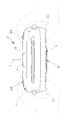
- FIG. 3 is a longitudinal sectional view taken along line III-III in FIG. 2. It is sectional drawing of a film unit. It is a back side perspective view of a digital camera with a printer. It is a rear view of the digital camera with a printer. It is explanatory drawing at the time of carrying out vertical shooting using the digital camera with a printer. It is explanatory drawing at the time of carrying out horizontal shooting using the digital camera with a printer. It is a top view of a digital camera with a printer. It is a front view of the digital camera with a printer of 2nd Embodiment.
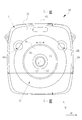
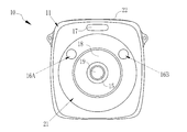
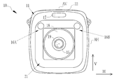
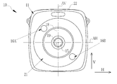
- a digital camera with a printer 10 includes a camera body 11, an imaging unit 12, and a printer unit 13 (see FIG. 3). On the front surface of the camera body 11, an imaging window 15, two release switches 16A and 16B, a flash 17, and an operation ring 18 are provided.
- the camera body 11 has a square shape when viewed from the front.
- the vertical dimension L1 in the vertical direction V (first direction) of the camera body 11 is a square in which the horizontal dimension L2 in the horizontal direction (second direction) orthogonal to the vertical direction V coincides with the vertical dimension. This includes the case where L1 and the horizontal dimension L2 substantially match.
- the film unit 23 as a recording medium used in the digital camera with printer 10 is also substantially square.
- the imaging window 15 is arranged at the front center of the camera body 11.
- the imaging window 15 exposes the imaging optical system 19 (see FIG. 3) constituting the imaging unit 12.
- the optical axis L of the imaging optical system 19 is orthogonal to the vertical direction V and the horizontal direction H.
- the imaging optical system 19 is located at the center in the vertical direction V and the horizontal direction H of the camera body 11.
- the imaging unit 12 is provided with an imaging optical system 19 and a solid-state imaging device 20 (see FIG. 3).
- the solid-state imaging device 20 is, for example, a CMOS (Complementary Metal Oxide Semiconductor) type image sensor, and has a light receiving surface constituted by a plurality of pixels (not shown) arranged in a two-dimensional matrix. Each pixel includes a photoelectric conversion element and photoelectrically converts a subject image formed on the light receiving surface by the imaging optical system 19 to generate an imaging signal.
- CMOS Complementary Metal Oxide Semiconductor
- the solid-state imaging device 20 includes a signal processing circuit (all not shown) such as a noise removal circuit, an auto gain controller, and an A / D conversion circuit.
- the noise removal circuit performs noise removal processing on the imaging signal.
- the auto gain controller amplifies the level of the imaging signal to an optimum value.
- the A / D conversion circuit converts the imaging signal into a digital signal and outputs it from the solid-state imaging device 20 to a built-in memory (not shown).
- the output signal of the solid-state imaging device 20 is image data (so-called RAW data) having one color signal for each pixel.
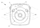
- a grip portion 21 is formed in the camera body 11 at a position that is line symmetric with respect to the vertical axis AV and line symmetric with respect to the horizontal axis AH.
- the grip portion 21 has an annular (ring shape) concave shape that is concave from the surrounding surface.
- the imaging optical system 19 is located at the center of the annular grip portion 21.
- the grip part 21 is formed so that the cross-sectional shape cut
- the line symmetric position includes a case where the line is substantially line symmetric.
- the release switches 16A and 16B are arranged at positions that are line-symmetric with respect to the vertical axis AV. Specifically, the release switches 16A and 16B are arranged at positions that are equidistant from the vertical axis AV. When at least one of the release switches 16A and 16B is pressed, a solid-state imaging device 20 described later is driven to capture a subject image.
- the release switches 16A and 16B are partially arranged on the grip portion 21.
- the release switches 16A and 16B arranged in the grip portion 21 are formed in a curved surface shape that is concave along the concave shape.
- the flash 17 is arranged in a position that coincides with the imaging optical system 19 in the horizontal direction H, that is, on the vertical axis AV.
- the term “matching” here includes the case where they are arranged at substantially matching positions.
- the flash 17 automatically irradiates the subject with illumination light when the exposure value is a predetermined value or less.
- the operation ring 18 is a ring-shaped operation member located between the grip portion 21 and the imaging optical system 19 and is attached to be rotatable around the optical axis L.
- the operation ring 18 is an operation member that is operated when the digital camera with a printer 10 is turned on or off.
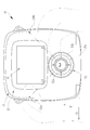
- a film discharge port 22 is provided at one end of the camera body 11 in the vertical direction V, that is, the upper surface. As will be described in detail later, the film unit 23 on which image printing has been completed is discharged from the film discharge port 22.
- a loading lid 24 is provided on the back side of the camera body 11.
- the loading lid 24 is attached via a hinge portion 24 a provided at the lower end of the camera body 11.
- the loading lid 24 has an open position (a position indicated by a two-dot chain line) for opening the film pack loading chamber 25 provided in the camera body 11, and a closed position (a position indicated by a solid line) for covering the film pack loading chamber 25. It is supported so that it can rotate freely.
- a film pack 26 is loaded into the film pack loading chamber 25.
- the film pack 26 includes a box-shaped case 26a and a lid 26b that covers the opening of the case 26a.
- a plurality of film units 23 are stored with the exposure surface 23a facing left in the drawing.
- a film delivery port 27 for sending the lowermost film unit 23 out of the film pack 26 is formed on the end surface of the case 26a facing the film discharge port 22.
- the film delivery port 27 is closed from the outside by a flexible light-shielding seal (not shown).
- a pair of openings 28a and 28b are formed in the lid 26b at predetermined intervals.
- a support piece 29, a film unit pressing plate 30, and the like are provided on the inner surface of the lid 26b.
- the openings 28a and 28b serve as inlets into which the pressing members 32a and 32b provided on the inner surface of the loading lid 24 enter when the loading lid 24 is closed.
- the support piece 29 supports the central portion of the film unit 23 from behind.
- the film unit pressing plate 30 is pressed by the pressing members 32a and 32b when the loading lid 24 is closed, and is curved so as to protrude toward the bottom surface of the case 26a. As a result, the lowermost film unit 23 is pressed against the bottom surface of the case 26a.
- the film unit 23 as a recording medium is a so-called mono-sheet type film. As shown in FIG. 4, the film unit 23 includes a mask sheet 33, a photosensitive sheet 34, a cover sheet 35, a developer pod 36, and a trap unit 37.
- the mask sheet 33 is formed of a thin plastic sheet and has a screen opening 33a.
- the photosensitive sheet 34 is provided with a photosensitive layer, a diffuse reflection layer, an image receiving layer, and the like.
- the cover sheet 35 has an exposure surface 23a that faces an exposure head 41 described later.
- the developer pod 36 is formed in a substantially bag shape, and a developer 38 is contained therein.
- the developer pod 36 is stuck on the end of the photosensitive sheet 34 on the side of the film delivery port 27 and is wrapped by the end of the mask sheet 33.
- the trap portion 37 is stuck on the end portion of the photosensitive sheet 34 opposite to the film delivery port 27 side, and is similarly wrapped by the end portion of the mask sheet 33.
- the photosensitive layer of the film unit 23 is irradiated with printing light to expose the photosensitive layer.
- the developer pod 36 is cleaved, and the developer 38 is poured into the gap 39 between the photosensitive sheet 34 and the cover sheet 35 and developed.
- a latent image is formed photochemically on the photosensitive layer, and this latent image is inverted by the diffuse reflection layer and transferred to the image receiving layer.
- a positive image appears on the positive image observation surface 40 of the photosensitive sheet 34 exposed from the screen opening 33a.
- the lowermost film unit 23 is moved out of the film pack 26 from the film delivery port 27 by a claw claw (not shown) inserted into a claw opening (not shown) on the bottom surface of the case 26a. Sent out.
- the film unit 23 (position indicated by a two-dot chain line) sent out of the film pack 26 is subjected to exposure processing and development processing by the printer unit 13 provided between the film delivery port 27 and the film discharge port 22.
- the printer unit 13 includes an exposure head 41 and a developer developing unit 42 which are arranged in order from the film delivery port 27 toward the film discharge port 22.
- the exposure head 41 includes, for example, a light source, a liquid crystal shutter, a lens, and the like, and is disposed at a position facing the film unit conveyance path. Specifically, the exposure head 41 is positioned between the flash 17 and the imaging unit 12 in the vertical direction V. Thereby, the camera body 11 can be thinned. Further, the film unit conveyance path through which the film unit 23 is conveyed by the developing solution developing unit 42 is located between the imaging unit 12 and a rear display unit 51 described later. Thereby, the camera body 11 can be downsized.
- the exposure head 41 irradiates the exposure surface 23a of the film unit 23 with linear print light parallel to the main scanning direction (film unit width direction). As a result, a line image having a gradation corresponding to the image data is exposed on the photosensitive layer of the film unit 23.
- the developer developing unit 42 includes transport rollers 43 and 44 and developing rollers 45 and 46.
- the conveying rollers 43 and 44 and the developing rollers 45 and 46 are rotationally driven by a motor (not shown).
- the conveying roller 44 is pressed to the conveying roller 43 side by a spring 47 as a pressing mechanism
- the developing roller 46 is pressed to the developing roller 45 side by a spring 48 as a pressing mechanism.
- the conveying rollers 43 and 44 convey the film units 23 toward the developing rollers 45 and 46 with both sides of the film unit 23 sent out from the film pack 26 interposed therebetween.
- the exposure position P at which the exposure head 41 exposes the printing light to the film unit 23 is located between the film delivery port 27 of the film pack 26 and the transport rollers 43 and 44. Thereby, the camera body 11 can be thinned.
- the developing rollers 45 and 46 nip the developer pod 36 while sandwiching the film unit 23 delivered from the transport rollers 43 and 44 over the entire width and transporting the film unit 23 toward the film discharge port 22.
- the liquid 38 is developed in the gap 39.
- the film unit 23 that has undergone development processing by the developing rollers 45 and 46 is conveyed to the film discharge port 22 and discharged out of the camera body 11.
- a rear display unit 51 and an operation unit 52 are provided on the outer surface of the loading lid 24, that is, on the rear surface of the camera body 11.
- the rear display unit 51 is configured by, for example, an LCD (Liquid Crystal Display) panel. Image data for one frame output from the solid-state imaging device 20 is sequentially input to the rear display unit 51 and displayed as a through image.
- the image data output from the solid-state image sensor 20 is subjected to matrix calculation, demosaic processing, ⁇ correction, luminance conversion, and color difference conversion by an image processing unit (not shown).
- image processing unit not shown
- compression processing is performed.
- the image processing and compressed image data are recorded in a built-in memory (not shown) such as a flash memory provided in the camera body 11.
- a pair of finger hooks 53A and 53B projecting from the back surface of the camera body 11 are provided on the outer surface of the loading lid 24 .
- the finger hooks 53A and 53B are formed in a triangular convex shape that protrudes rearward from the camera body 11 continuously from both side surfaces of the camera body 11.
- the operation unit 52 is provided with a plurality of switches for performing various operations of the digital camera with printer 10 in addition to the menu switch 52A and the print switch 52B described above.
- the display unit 51 and the operation unit 52 are located between the finger hooks 53A and 53B in the horizontal direction H. More specifically, the operation unit 52 is arranged at a position where the distances L3 and L4 from the center of the operation unit 52 to the vertices of the finger hooks 53A and 53B are equal.
- FIG. 7A, 7B and 8. When the operation of the operation ring 18 is turned to turn on the power of the digital camera 10 with a printer, power is supplied to each part.
- the imaging mode is set and the solid-state imaging device 20 of the imaging unit 12 is driven.
- the solid-state imaging device 20 continuously captures subject images, and the images are displayed on the rear display unit 51. The photographer frames the subject while looking at the rear display unit 51.
- the photographer shoots according to the framing by vertical shooting with the camera body 11 in the vertical direction (see FIG. 7A) or horizontal shooting with the camera body in the horizontal direction (see FIG. 7B). Since the camera body 11 of the digital camera with printer 10 is formed with the grip portion 21, as shown in FIGS. 7A and 7B, the photographer's right hand and left hand can be used for both vertical shooting and horizontal shooting. The camera body 11 can be securely gripped. For this reason, the camera body 11 is easy to hold and the feeling of holding is improved.
- the camera body 11 is square, the photographer can hold the camera body 11 with the same holding method and the same force in both vertical shooting and horizontal shooting. The ease of holding and the feeling of holding are further improved.
- the grip portion 21 is formed in a ring shape, the camera body 11 can be reliably held even when the camera body 11 is held at an angle such as an intermediate position between vertical shooting and horizontal shooting.
- the image data output from the solid-state image sensor 20 is recorded in the built-in memory.
- the photographer switches the print switch of the operation unit 52.
- the button 52B By pressing the button 52B, the printing process by the printer unit 13 is started.
- the film unit 23 discharged out of the film pack 26 from the film delivery port 27 is nipped and conveyed by the conveying rollers 43 and 44. Then, exposure by the exposure head 41 is performed during the conveyance.
- the exposure head 41 exposes an image (latent image) for one screen onto the photosensitive layer of the film unit 23 based on the image data recorded in the built-in memory. Subsequently, the film unit 23 is conveyed toward the developing rollers 45 and 46 and is nipped and conveyed by the developing rollers 45 and 46. As a result, the developer 38 is developed in the gap 39 (see FIG. 4) as described above.
- the film unit 23 that has undergone development processing is conveyed to the film discharge port 22 and discharged out of the camera body 11. Then, after a predetermined time has elapsed, a positive image appears on the positive image observation surface 40 of the discharged film unit 23.
- the photographer can recognize the positions of the release switches 16A and 16B only with the sense of a fingertip. , Operability is improved. Furthermore, since the release switches 16A and 16B are arranged at positions that are line-symmetric with respect to the vertical axis AV, it is easy for the photographer to perform a pressing operation in both vertical shooting and horizontal shooting.
- the camera body 11 is provided with a pair of finger hooks 53A and 53B protruding from the back surface, as shown in FIG. 8, the photographer holds the camera body 11 with his / her thumbs on the finger hooks 53A and 53B. It is easy to do. Furthermore, since the operation unit 52 is located between the finger hooks 53A and 53B, various operations of the digital camera with printer 10 can be easily performed while holding the camera body 11.
- part of the release switches 16A and 16B is arranged on the grip part 21, but in the second embodiment, as shown in FIG. It is arranged in.
- the release switches 16A and 16B are formed in a curved surface shape that is concave along the concave shape.
- the photographer can recognize the positions of the release switches 16A and 16B only with the sense of the fingertip, and the operability is improved.
- the grip part 21 is an annular
- the imaging optical system 19 is located at the center of the annular grip portion 21. That is, as in the first embodiment, the grip portion 21 is formed at a position that is line symmetric with respect to the vertical axis AV and line symmetric with respect to the horizontal axis AH.
- all of the release switches 16A and 16B are arranged in the grip portion 21, but a part of the release switches 16A and 16B is arranged in the grip portion 21 as in the first embodiment. May be.
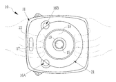
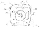
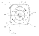
- the grip part 21 is one ring-shaped concave shape, but in 3rd Embodiment, as shown in FIG. 11, the grip part 21 has several concave shape or convex shape. It is. Specifically, the grip portion 21 is composed of four concave shapes 21A to 21D. The concave shapes 21A and 21B are in positions symmetrical with respect to the horizontal axis AH, and the concave shapes 21C and 21D are They are formed at positions that are line-symmetric with respect to the vertical axis AV. Further, as in the first embodiment, part of the release switches 16A and 16B are arranged in the grip part 21, but as in the second embodiment, all the release switches 16A and 16B are in the grip part 21. It may be arranged.
- the release switches 16A and 16B are arranged at positions that are line-symmetric with respect to the vertical axis AV.
- the fifth embodiment as shown in FIG. It is arranged at a position that is 180 degrees rotationally symmetric about the center, specifically, a position that is 180 degrees rotationally symmetric about the optical axis L.
- all of the release switches 16A and 16B are arranged in the grip part 21, but a part of the release switches 16A and 16B is arranged in the grip part 21 as in the first embodiment. May be.
- the camera body 11 is provided with two release switches 16A and 16B.
- the release switches 16A to 16D are arranged at positions that are line-symmetric with respect to the vertical axis AV and line-symmetric with respect to the horizontal axis AH.
- all of the release switches 16A to 16D are arranged in the grip part 21, but a part of the release switches 16A to 16D is arranged in the grip part 21 as in the first embodiment. May be.
- the grip portion 21 has a concave shape that is concave from the surrounding surface, but is not limited thereto, and may be formed in a convex shape that is convex from the peripheral surface. Good.
- the release switch is preferably formed in a curved shape that is convex along the convex shape of the grip portion 21.
- the first direction is the vertical direction V and the second direction is the horizontal direction H.
- the first direction may be the horizontal direction H and the second direction may be the vertical direction V.
- a monosheet type instant film is used as the recording medium, and a film pack containing the instant film is used as the recording medium pack.
- the recording medium is a heat sensitive medium.
- a heat-sensitive recording paper, a plain paper, a special paper (such as a surface-coated paper), and an OHP sheet can be used.
- thermal recording paper thermal recording is performed by a thermal head.
- plain paper or the like is used as a recording medium, recording is performed by ink jet, heat melting, thermal transfer, or the like.
Landscapes
- Physics & Mathematics (AREA)
- General Physics & Mathematics (AREA)
- Engineering & Computer Science (AREA)
- Multimedia (AREA)
- Signal Processing (AREA)
- Microelectronics & Electronic Packaging (AREA)
- Cameras Adapted For Combination With Other Photographic Or Optical Apparatuses (AREA)
- Studio Devices (AREA)
- Camera Bodies And Camera Details Or Accessories (AREA)
- Stroboscope Apparatuses (AREA)
- Cameras In General (AREA)
Priority Applications (3)
| Application Number | Priority Date | Filing Date | Title |
|---|---|---|---|
| CN201780056613.9A CN109716231B (zh) | 2016-09-16 | 2017-09-13 | 带打印机的数码相机 |
| EP17850941.0A EP3514619B1 (en) | 2016-09-16 | 2017-09-13 | Printer-equipped digital camera |
| US16/354,531 US10642129B2 (en) | 2016-09-16 | 2019-03-15 | Digital camera including printer |
Applications Claiming Priority (2)
| Application Number | Priority Date | Filing Date | Title |
|---|---|---|---|
| JP2016181503A JP6568029B2 (ja) | 2016-09-16 | 2016-09-16 | プリンタ付きデジタルカメラ |
| JP2016-181503 | 2016-09-16 |
Related Child Applications (1)
| Application Number | Title | Priority Date | Filing Date |
|---|---|---|---|
| US16/354,531 Continuation US10642129B2 (en) | 2016-09-16 | 2019-03-15 | Digital camera including printer |
Publications (1)
| Publication Number | Publication Date |
|---|---|
| WO2018052040A1 true WO2018052040A1 (ja) | 2018-03-22 |
Family
ID=61619570
Family Applications (1)
| Application Number | Title | Priority Date | Filing Date |
|---|---|---|---|
| PCT/JP2017/033125 Ceased WO2018052040A1 (ja) | 2016-09-16 | 2017-09-13 | プリンタ付きデジタルカメラ |
Country Status (5)
| Country | Link |
|---|---|
| US (1) | US10642129B2 (enExample) |
| EP (1) | EP3514619B1 (enExample) |
| JP (1) | JP6568029B2 (enExample) |
| CN (1) | CN109716231B (enExample) |
| WO (1) | WO2018052040A1 (enExample) |
Families Citing this family (7)
| Publication number | Priority date | Publication date | Assignee | Title |
|---|---|---|---|---|
| DE102018100728A1 (de) * | 2018-01-15 | 2019-07-18 | Xarpotech Ug (Haftungsbeschränkt) | Organische Photorezeptoren |
| JP1706220S (enExample) * | 2021-03-17 | 2022-01-28 | ||
| JP1711074S (enExample) * | 2021-06-21 | 2022-03-29 | ||
| JP1719323S (ja) * | 2021-09-16 | 2022-07-08 | インスタントカメラ | |
| JP1719324S (ja) * | 2021-09-16 | 2022-07-08 | インスタントカメラ | |
| JP1719325S (ja) * | 2021-09-16 | 2022-07-08 | インスタントカメラ | |
| USD1077890S1 (en) * | 2025-01-06 | 2025-06-03 | Shenzhen SiXing Digital Technology Co., Ltd. | Children's camera |
Citations (11)
| Publication number | Priority date | Publication date | Assignee | Title |
|---|---|---|---|---|
| JPH1010626A (ja) * | 1996-06-24 | 1998-01-16 | Canon Inc | カメラ |
| JPH114372A (ja) * | 1997-06-11 | 1999-01-06 | Sanyo Electric Co Ltd | 画像印刷装置及びカメラ |
| JPH11317897A (ja) * | 1998-05-07 | 1999-11-16 | Casio Comput Co Ltd | プリンタ付きカメラ装置 |
| JP2002040534A (ja) | 2000-07-27 | 2002-02-06 | Nikon Corp | カメラ |
| JP2002296659A (ja) | 2000-10-02 | 2002-10-09 | Fuji Photo Film Co Ltd | カメラ |
| JP2003134372A (ja) * | 2001-10-23 | 2003-05-09 | Fuji Photo Film Co Ltd | カメラ |
| JP2003330084A (ja) * | 2002-05-09 | 2003-11-19 | Fuji Photo Film Co Ltd | カメラ |
| JP2004340991A (ja) * | 2003-05-13 | 2004-12-02 | Fuji Photo Film Co Ltd | カメラ |
| JP2007329657A (ja) * | 2006-06-07 | 2007-12-20 | Canon Inc | 撮像装置 |
| JP2014126848A (ja) * | 2012-12-27 | 2014-07-07 | Canon Inc | 撮像装置 |
| JP2015084075A (ja) * | 2013-08-19 | 2015-04-30 | ソニー株式会社 | 撮像装置 |
Family Cites Families (19)
| Publication number | Priority date | Publication date | Assignee | Title |
|---|---|---|---|---|
| US3530778A (en) * | 1968-04-01 | 1970-09-29 | Polaroid Corp | Photographic camera |
| US4181414A (en) * | 1976-03-12 | 1980-01-01 | Canon Kabushiki Kaisha | Self developing camera with film feedout control |
| JPS63150939U (enExample) * | 1987-03-25 | 1988-10-04 | ||
| US5218390A (en) * | 1991-04-15 | 1993-06-08 | Eastman Kodak Company | Compact camera with integral body grip |
| JPH11249233A (ja) * | 1998-02-27 | 1999-09-17 | Fuji Photo Film Co Ltd | プリンタ付き電子カメラ |
| AUPQ056099A0 (en) * | 1999-05-25 | 1999-06-17 | Silverbrook Research Pty Ltd | A method and apparatus (pprint01) |
| JP3999449B2 (ja) * | 2000-07-27 | 2007-10-31 | 富士フイルム株式会社 | フイルム押さえ装置 |
| US6301438B1 (en) * | 2000-09-13 | 2001-10-09 | Polaroid Corporation | Film advancement assembly for a self-developing camera |
| US6504999B2 (en) * | 2000-10-02 | 2003-01-07 | Fuji Photo Film Co., Ltd. | Camera with printer |
| JP2002137451A (ja) * | 2000-11-07 | 2002-05-14 | Fuji Photo Film Co Ltd | 光ヘッド装置 |
| JP2002330373A (ja) * | 2001-05-07 | 2002-11-15 | Canon Inc | カートリッジロック装置、撮像装置及びカートリッジロック方法 |
| JP4515665B2 (ja) * | 2001-07-24 | 2010-08-04 | ローム株式会社 | プリント機能付きカメラ |
| JP2004212831A (ja) * | 2003-01-08 | 2004-07-29 | Fuji Photo Film Co Ltd | インスタントカメラおよび記録装置 |
| JP4339218B2 (ja) * | 2004-09-24 | 2009-10-07 | 富士フイルム株式会社 | 画像記録装置 |
| CN2786655Y (zh) * | 2005-02-22 | 2006-06-07 | 赵永生 | “612”宽幅120照相机 |
| JP5541430B1 (ja) | 2013-08-19 | 2014-07-09 | ソニー株式会社 | 撮像ユニット、装着装置 |
| JP6296894B2 (ja) * | 2014-05-14 | 2018-03-20 | キヤノン株式会社 | 電子機器 |
| EP3168682B1 (en) * | 2015-11-16 | 2017-12-27 | Axis AB | A lens arrangement and a monitoring camera comprising the lens arrangement |
| WO2018147069A1 (ja) * | 2017-02-10 | 2018-08-16 | 富士フイルム株式会社 | インスタントフィルムパック及びそれを用いる装置類 |
-
2016
- 2016-09-16 JP JP2016181503A patent/JP6568029B2/ja active Active
-
2017
- 2017-09-13 EP EP17850941.0A patent/EP3514619B1/en active Active
- 2017-09-13 WO PCT/JP2017/033125 patent/WO2018052040A1/ja not_active Ceased
- 2017-09-13 CN CN201780056613.9A patent/CN109716231B/zh active Active
-
2019
- 2019-03-15 US US16/354,531 patent/US10642129B2/en active Active
Patent Citations (11)
| Publication number | Priority date | Publication date | Assignee | Title |
|---|---|---|---|---|
| JPH1010626A (ja) * | 1996-06-24 | 1998-01-16 | Canon Inc | カメラ |
| JPH114372A (ja) * | 1997-06-11 | 1999-01-06 | Sanyo Electric Co Ltd | 画像印刷装置及びカメラ |
| JPH11317897A (ja) * | 1998-05-07 | 1999-11-16 | Casio Comput Co Ltd | プリンタ付きカメラ装置 |
| JP2002040534A (ja) | 2000-07-27 | 2002-02-06 | Nikon Corp | カメラ |
| JP2002296659A (ja) | 2000-10-02 | 2002-10-09 | Fuji Photo Film Co Ltd | カメラ |
| JP2003134372A (ja) * | 2001-10-23 | 2003-05-09 | Fuji Photo Film Co Ltd | カメラ |
| JP2003330084A (ja) * | 2002-05-09 | 2003-11-19 | Fuji Photo Film Co Ltd | カメラ |
| JP2004340991A (ja) * | 2003-05-13 | 2004-12-02 | Fuji Photo Film Co Ltd | カメラ |
| JP2007329657A (ja) * | 2006-06-07 | 2007-12-20 | Canon Inc | 撮像装置 |
| JP2014126848A (ja) * | 2012-12-27 | 2014-07-07 | Canon Inc | 撮像装置 |
| JP2015084075A (ja) * | 2013-08-19 | 2015-04-30 | ソニー株式会社 | 撮像装置 |
Non-Patent Citations (1)
| Title |
|---|
| See also references of EP3514619A4 |
Also Published As
| Publication number | Publication date |
|---|---|
| JP2018045178A (ja) | 2018-03-22 |
| CN109716231A (zh) | 2019-05-03 |
| US10642129B2 (en) | 2020-05-05 |
| EP3514619A4 (en) | 2019-07-24 |
| US20190212635A1 (en) | 2019-07-11 |
| EP3514619B1 (en) | 2023-08-09 |
| JP6568029B2 (ja) | 2019-08-28 |
| EP3514619A1 (en) | 2019-07-24 |
| CN109716231B (zh) | 2021-08-17 |
Similar Documents
| Publication | Publication Date | Title |
|---|---|---|
| JP6568029B2 (ja) | プリンタ付きデジタルカメラ | |
| JP3862132B2 (ja) | 電子スチルカメラ | |
| CN108234803B (zh) | 打印机及带有打印机的数码相机以及打印机的信息显示方法 | |
| US11520215B2 (en) | Printer and digital camera with printer | |
| CN112689795B (zh) | 带打印机的照相机及其显示控制方法 | |
| US11709413B2 (en) | Printer device and camera with printer | |
| US11736631B2 (en) | Printer-equipped digital camera and displaying control method thereof | |
| JP2002120407A (ja) | 光プリンタ | |
| US11463593B2 (en) | Printer-equipped camera | |
| CN117099042A (zh) | 打印机装置及带打印机的数码相机 | |
| JP2000209469A (ja) | 電子スチルカメラ | |
| JP2003043572A (ja) | プリンタ内蔵デジタルカメラ | |
| JP2004078081A (ja) | カメラ | |
| JP2002296659A (ja) | カメラ | |
| JP3781329B2 (ja) | デジタルプリントシステム | |
| JP2005159571A (ja) | フィルム式カメラ用デジタルユニット | |
| JP2007124006A (ja) | 撮像ユニット、及び撮像装置 | |
| JP2007130899A (ja) | カメラシステム | |
| JP2002072369A (ja) | プリンタ | |
| JPH1146344A (ja) | 画像記録装置および撮影装置 | |
| JP2001318452A (ja) | インスタントプリンタ及びプリント方法 | |
| JP2007111905A (ja) | 撮像ユニット、携帯型プリンタ、及びプリントシステム | |
| JP2002014416A (ja) | プリンタ付き電子スチルカメラ | |
| JP2015184500A (ja) | 撮像装置 |
Legal Events
| Date | Code | Title | Description |
|---|---|---|---|
| 121 | Ep: the epo has been informed by wipo that ep was designated in this application |
Ref document number: 17850941 Country of ref document: EP Kind code of ref document: A1 |
|
| NENP | Non-entry into the national phase |
Ref country code: DE |
|
| ENP | Entry into the national phase |
Ref document number: 2017850941 Country of ref document: EP Effective date: 20190416 |