WO2018047701A1 - シフト装置 - Google Patents
シフト装置 Download PDFInfo
- Publication number
- WO2018047701A1 WO2018047701A1 PCT/JP2017/031252 JP2017031252W WO2018047701A1 WO 2018047701 A1 WO2018047701 A1 WO 2018047701A1 JP 2017031252 W JP2017031252 W JP 2017031252W WO 2018047701 A1 WO2018047701 A1 WO 2018047701A1
- Authority
- WO
- WIPO (PCT)
- Prior art keywords
- shift
- lever
- lock bar
- groove
- moved
- Prior art date
- Legal status (The legal status is an assumption and is not a legal conclusion. Google has not performed a legal analysis and makes no representation as to the accuracy of the status listed.)
- Ceased
Links
Images


Classifications
-
- F—MECHANICAL ENGINEERING; LIGHTING; HEATING; WEAPONS; BLASTING
- F16—ENGINEERING ELEMENTS AND UNITS; GENERAL MEASURES FOR PRODUCING AND MAINTAINING EFFECTIVE FUNCTIONING OF MACHINES OR INSTALLATIONS; THERMAL INSULATION IN GENERAL
- F16H—GEARING
- F16H59/00—Control inputs to control units of change-speed- or reversing-gearings for conveying rotary motion
- F16H59/02—Selector apparatus
- F16H59/08—Range selector apparatus
-
- F—MECHANICAL ENGINEERING; LIGHTING; HEATING; WEAPONS; BLASTING
- F16—ENGINEERING ELEMENTS AND UNITS; GENERAL MEASURES FOR PRODUCING AND MAINTAINING EFFECTIVE FUNCTIONING OF MACHINES OR INSTALLATIONS; THERMAL INSULATION IN GENERAL
- F16H—GEARING
- F16H59/00—Control inputs to control units of change-speed- or reversing-gearings for conveying rotary motion
- F16H59/02—Selector apparatus
- F16H59/08—Range selector apparatus
- F16H59/10—Range selector apparatus comprising levers
-
- B—PERFORMING OPERATIONS; TRANSPORTING
- B60—VEHICLES IN GENERAL
- B60K—ARRANGEMENT OR MOUNTING OF PROPULSION UNITS OR OF TRANSMISSIONS IN VEHICLES; ARRANGEMENT OR MOUNTING OF PLURAL DIVERSE PRIME-MOVERS IN VEHICLES; AUXILIARY DRIVES FOR VEHICLES; INSTRUMENTATION OR DASHBOARDS FOR VEHICLES; ARRANGEMENTS IN CONNECTION WITH COOLING, AIR INTAKE, GAS EXHAUST OR FUEL SUPPLY OF PROPULSION UNITS IN VEHICLES
- B60K20/00—Arrangement or mounting of change-speed gearing control devices in vehicles
- B60K20/02—Arrangement or mounting of change-speed gearing control devices in vehicles of initiating means
-
- F—MECHANICAL ENGINEERING; LIGHTING; HEATING; WEAPONS; BLASTING
- F16—ENGINEERING ELEMENTS AND UNITS; GENERAL MEASURES FOR PRODUCING AND MAINTAINING EFFECTIVE FUNCTIONING OF MACHINES OR INSTALLATIONS; THERMAL INSULATION IN GENERAL
- F16H—GEARING
- F16H59/00—Control inputs to control units of change-speed- or reversing-gearings for conveying rotary motion
- F16H59/02—Selector apparatus
- F16H59/08—Range selector apparatus
- F16H59/10—Range selector apparatus comprising levers
- F16H59/105—Range selector apparatus comprising levers consisting of electrical switches or sensors
-
- F—MECHANICAL ENGINEERING; LIGHTING; HEATING; WEAPONS; BLASTING
- F16—ENGINEERING ELEMENTS AND UNITS; GENERAL MEASURES FOR PRODUCING AND MAINTAINING EFFECTIVE FUNCTIONING OF MACHINES OR INSTALLATIONS; THERMAL INSULATION IN GENERAL
- F16H—GEARING
- F16H61/00—Control functions within control units of change-speed- or reversing-gearings for conveying rotary motion ; Control of exclusively fluid gearing, friction gearing, gearings with endless flexible members or other particular types of gearing
- F16H61/22—Locking of the control input devices
-
- G—PHYSICS
- G05—CONTROLLING; REGULATING
- G05G—CONTROL DEVICES OR SYSTEMS INSOFAR AS CHARACTERISED BY MECHANICAL FEATURES ONLY
- G05G1/00—Controlling members, e.g. knobs or handles; Assemblies or arrangements thereof; Indicating position of controlling members
- G05G1/04—Controlling members for hand actuation by pivoting movement, e.g. levers
-
- B—PERFORMING OPERATIONS; TRANSPORTING
- B60—VEHICLES IN GENERAL
- B60K—ARRANGEMENT OR MOUNTING OF PROPULSION UNITS OR OF TRANSMISSIONS IN VEHICLES; ARRANGEMENT OR MOUNTING OF PLURAL DIVERSE PRIME-MOVERS IN VEHICLES; AUXILIARY DRIVES FOR VEHICLES; INSTRUMENTATION OR DASHBOARDS FOR VEHICLES; ARRANGEMENTS IN CONNECTION WITH COOLING, AIR INTAKE, GAS EXHAUST OR FUEL SUPPLY OF PROPULSION UNITS IN VEHICLES
- B60K20/00—Arrangement or mounting of change-speed gearing control devices in vehicles
- B60K20/02—Arrangement or mounting of change-speed gearing control devices in vehicles of initiating means
- B60K20/04—Arrangement or mounting of change-speed gearing control devices in vehicles of initiating means floor mounted
-
- F—MECHANICAL ENGINEERING; LIGHTING; HEATING; WEAPONS; BLASTING
- F16—ENGINEERING ELEMENTS AND UNITS; GENERAL MEASURES FOR PRODUCING AND MAINTAINING EFFECTIVE FUNCTIONING OF MACHINES OR INSTALLATIONS; THERMAL INSULATION IN GENERAL
- F16H—GEARING
- F16H59/00—Control inputs to control units of change-speed- or reversing-gearings for conveying rotary motion
- F16H59/02—Selector apparatus
- F16H2059/0221—Selector apparatus for selecting modes, e.g. sport, normal, economy
-
- F—MECHANICAL ENGINEERING; LIGHTING; HEATING; WEAPONS; BLASTING
- F16—ENGINEERING ELEMENTS AND UNITS; GENERAL MEASURES FOR PRODUCING AND MAINTAINING EFFECTIVE FUNCTIONING OF MACHINES OR INSTALLATIONS; THERMAL INSULATION IN GENERAL
- F16H—GEARING
- F16H59/00—Control inputs to control units of change-speed- or reversing-gearings for conveying rotary motion
- F16H59/02—Selector apparatus
- F16H59/08—Range selector apparatus
- F16H2059/081—Range selector apparatus using knops or discs for rotary range selection
-
- F—MECHANICAL ENGINEERING; LIGHTING; HEATING; WEAPONS; BLASTING
- F16—ENGINEERING ELEMENTS AND UNITS; GENERAL MEASURES FOR PRODUCING AND MAINTAINING EFFECTIVE FUNCTIONING OF MACHINES OR INSTALLATIONS; THERMAL INSULATION IN GENERAL
- F16H—GEARING
- F16H61/00—Control functions within control units of change-speed- or reversing-gearings for conveying rotary motion ; Control of exclusively fluid gearing, friction gearing, gearings with endless flexible members or other particular types of gearing
- F16H61/24—Providing feel, e.g. to enable selection
- F16H2061/243—Cams or detent arrays for guiding and providing feel
-
- F—MECHANICAL ENGINEERING; LIGHTING; HEATING; WEAPONS; BLASTING
- F16—ENGINEERING ELEMENTS AND UNITS; GENERAL MEASURES FOR PRODUCING AND MAINTAINING EFFECTIVE FUNCTIONING OF MACHINES OR INSTALLATIONS; THERMAL INSULATION IN GENERAL
- F16H—GEARING
- F16H61/00—Control functions within control units of change-speed- or reversing-gearings for conveying rotary motion ; Control of exclusively fluid gearing, friction gearing, gearings with endless flexible members or other particular types of gearing
- F16H61/24—Providing feel, e.g. to enable selection
Definitions
- the present invention relates to a shift device in which a shift body is moved and a shift position of the shift body is changed.
- the restriction link is disposed at the restriction position, the change of the shift position of the shift lever is restricted, the button is operated, and the solenoid is driven.
- the restriction link is rotated from the restriction position to the permission position, and the change of the shift position of the shift lever is permitted.
- the present invention has an object to obtain a shift device capable of appropriately changing the restriction and permission for changing the shift position of the shift body in consideration of the above facts.
- the shift device includes a shift body that is moved and the shift position is changed, and the shift body that is disposed at the restriction position is restricted from changing the shift position of the shift body and is moved from the restriction position to the permitted position.
- a restricting portion that is allowed to change the shift position of the shift body, an operation portion that is made operable, and a rotational position is changed by operating the operating portion, so that the restricting portion is allowed to move from the restricted position.
- a rotating part to which the restricting part is moved as the rotational position is changed.
- the shift device includes a shift body that is moved and the shift position is changed, and the shift body that is disposed at the restriction position is restricted from changing the shift position of the shift body and is moved from the restriction position to the permitted position.
- a change of the shift position of the shift body is permitted, and a restriction part whose restriction position is set to a fixed position, and an operation part that is operated to move the restriction part from the restriction position to the permission position; Is provided.
- the shift device includes a shift body that is moved to change the shift position, and the shift body that is disposed at the restriction position is restricted from changing the shift position of the shift body, and is moved from the restriction position to the permitted position. And a control unit that is allowed to change the shift position of the shift body, an operation unit that can be operated, and driven by operating the operation unit to move the control unit from the control position to the permission position.
- a motor that is allowed to change the shift position of the shift body, an operation unit that can be operated, and driven by operating the operation unit to move the control unit from the control position to the permission position.
- the shift body is moved and the shift position of the shift body is changed.
- the restricting portion is arranged at the restricting position, the change of the shift position of the shift body is restricted, and the operating portion is operated to change the rotation position of the rotating portion, so that the restricting portion is moved from the restricting position.
- the shift position of the shift body is allowed to be changed by being moved to the permission position.
- the restricting part is moved. For this reason, the precision of the rotation position of the rotation part for the restriction part to be arranged at at least one of the restriction position and the permission position can be lowered, and the restriction and permission for changing the shift position of the shift body can be changed appropriately.
- the shift body is moved and the shift position of the shift body is changed.
- the restricting portion is arranged at the restricting position, and the change of the shift position of the shift body is restricted. By operating the operation portion, the restricting portion is moved from the restricting position to the permission position, and Changing the shift position is allowed.
- the restriction position of the restriction part is set to a fixed position. For this reason, the movement stroke between the restriction
- the shift body is moved and the shift position of the shift body is changed.
- the restricting portion is arranged at the restricting position, and the change of the shift position of the shift body is restricted. By operating the operation portion, the restricting portion is moved from the restricting position to the permission position, and Changing the shift position is allowed.
- the motor is driven to move the regulating unit from the regulated position to the permitted position. For this reason, even when the movement resistance of the restricting portion is large, the restricting portion can be moved from the restricting position to the permission position, and the restriction and permission for changing the shift position of the shift body can be appropriately changed.
- FIG. 1 shows a perspective view of a shift lever device 10 as a shift device according to an embodiment of the present invention when viewed from the front diagonal left.
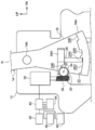
- FIG. 2 shows the main part of the shift lever device 10. It is shown in the side view seen from the right.
- the front of the shift lever device 10 is indicated by an arrow FR
- the right side of the shift lever device 10 is indicated by an arrow RH
- the upper side of the shift lever device 10 is indicated by an arrow UP.
- the shift lever device 10 is a so-called straight type.
- the shift lever device 10 is a floor type and is installed on the floor (vehicle body side) of the passenger compartment in the vehicle width direction of the driver's seat (not shown) of the vehicle (automobile).
- the front, right and upper sides of the vehicle are directed to the front, right and upper sides of the vehicle, respectively.
- the shift lever device 10 is provided with a resin-made substantially rectangular box-shaped plate 12 (housing) as a support, and the plate 12 is fixed to the floor of the passenger compartment.
- the shift lever device 10 is installed on the floor of the passenger compartment.
- a substantially long rod-shaped lever 14 as a shift body is disposed in the plate 12.
- a cylindrical support shaft 14A is provided at an intermediate portion in the vertical direction of the lever 14, and the lever 14 is supported on the support shaft 14A so as to be rotatable (movable) in the front-rear direction within a predetermined range above the plate 12.
- the lever 14 extends upward from the plate 12, and the upper portion of the lever 14 is curved in the longitudinal direction.
- a knob 16 as a grip portion is integrally provided at the upper end portion (tip portion) of the lever 14, and the lever 14 is rotated in a state where the knob 16 is gripped by a vehicle occupant (especially a driver). Has been made possible. As a result, the lever 14 shifts from the front side toward the rear side as a shift position “P” position (parking position), “R” position (reverse position), “N” position (neutral position), and “D” position. It can be rotated to (drive position).
- the knob 16 is provided with a button (switch, not shown) as an operation unit, and the button can be operated (pressed) by an occupant.
- a shift detection mechanism 44 (see FIG. 2) is provided in the plate 12, and when the lever 14 is disposed at the “P” position, the lever 14 is shifted from the “P” position. The detection mechanism 44 detects.
- An operation detection mechanism 46 (see FIG. 2) is electrically connected to the button of the knob 16, and when the button is operated, the operation detection mechanism 46 detects that the button has been operated.
- a substantially fan-shaped rotating plate 18 is provided below the lever 14, and the lower surface of the rotating plate 18 is curved along the rotating circumferential direction of the lever 14.
- a projecting portion 18A is integrally provided at the lower end portion of the rotating plate 18, and the projecting portion 18A projects to the right and extends along the rotating circumferential direction of the lever 14.
- a detent groove 20 having a predetermined shape as an engaging portion is formed on the upper surface of the protrusion 18A, and the detent groove 20 is disposed in the entire extending direction of the protrusion 18A.
- a P-groove 20P is formed at the front end portion of the detent groove 20, and the rear surface of the P-groove 20P is disposed substantially perpendicular to the rotational circumferential direction of the lever 14.
- An R-groove 20R is formed in the front-rear direction intermediate portion of the detent groove 20, and the R-groove 20R is disposed so that the front surface is substantially perpendicular to the rotation circumferential direction of the lever 14, and the rear surface is directed toward the rear side. It is inclined in the direction toward the upper side.
- An N-groove 20N is formed in the detent groove 20 on the rear side of the R-groove 20R, and the front surface of the N-groove 20N is disposed substantially perpendicular to the rotational circumferential direction of the lever 14.
- a D groove 20D is formed on the rear side of the N groove 20N, and the D groove 20D communicates with the rear side of the N groove 20N.
- the upper surface of the detent groove 20 (the upper surface between the P groove 20P and the R groove 20R and the upper surface between the R groove 20R and the N groove 20N) has the same curved surface along the rotation circumferential direction of the lever 14.
- the lower surfaces of the detent grooves 20 (the lower surfaces of the P groove 20P, the R groove 20R, the N groove 20N, and the D groove 20D) are the same curved surface along the rotational circumferential direction of the lever 14.
- a substantially flat support plate 22 as a support member is fixed in the plate 12, and the support plate 22 is arranged vertically in the left-right direction.
- the support plate 22 is disposed on the upper side of the protruding portion 18 ⁇ / b> A of the lever 14, and the protruding portion 18 ⁇ / b> A protrudes on the right side of the support plate 22.
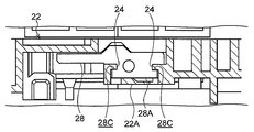
- the support plate 22 is provided with a substantially rectangular parallelepiped box-like support frame 22 ⁇ / b> A (see FIG. 5), and the left wall of the support frame 22 ⁇ / b> A is formed by the support plate 22.
- the support frame 22A protrudes to the right side, and the entire lower surface of the support frame 22A and the left side portion of the rear surface are open.
- a guide section 24 having a rectangular cross section is integrally provided at the center in the left-right direction of the front wall of the support frame 22A and at the left end of the rear wall of the support frame 22A.
- the pair of guide sections 24 are respectively arranged in the vertical direction. While being stretched, they are opposed in the front-rear direction.
- the lower end of the support plate 22 is integrally provided with a restricting protrusion 26, and the restricting protrusion 26 protrudes to the right.
- a restriction groove 26A having a rectangular cross section is formed in the restriction protrusion 26. The restriction groove 26A penetrates the restriction protrusion 26 in the vertical direction and is opened to the right.
- a substantially T-shaped plate-like lock bar 28 On the right side of the support plate 22 is provided a substantially T-shaped plate-like lock bar 28 as a restricting portion, and a substantially rectangular parallelepiped protrusion 28 ⁇ / b> A (see FIG. 5) on the front portion of the upper portion of the lock bar 28.
- the protrusion 28 ⁇ / b> A protrudes to the right, and the front portion (including the protrusion 28 ⁇ / b> A) of the upper portion of the lock bar 28 is inserted into the support frame 22 ⁇ / b> A of the support plate 22.
- a guide groove 28C having a rectangular cross section is formed on the front surface and the rear surface of the protrusion 28A, and the pair of guide grooves 28C are extended in the vertical direction to penetrate the protrusion 28A and protrude in the front-rear direction. It is opposed across the part 28A.
- the guide groove 28C is fitted with the guide portion 24 of the support frame 22A. This restricts the movement of the lock bar 28 (projection portion 28A) in the front-rear direction and the left-right direction, and the guide groove 28C The lock bar 28 is moved in the vertical direction by being guided by the guide unit 24 and moved in the vertical direction.
- the lower part of the lock bar 28 is inserted into the restriction groove 26A of the restriction projection 26 of the support plate 22 so as to be movable in the vertical direction, and the lower part of the lock bar 28 is fitted in the restriction groove 26A in the front-rear direction, Movement in the direction is restricted.
- a concave portion 28B having a substantially rectangular cross section is formed in the rear portion of the upper portion of the lock bar 28. The concave portion 28B is open to both sides in the left-right direction, the lower side, and the rear side.
- Biasing means (not shown) is spanned between the support plate 22 (which may be the support frame 22A) and the lock bar 28, and the lock bar 28 is urged downward by the biasing means. Yes.
- the lock bar 28 is moved to the lower restriction position by the urging force of the urging means.
- the lower end portions of the lock bars 28 are inserted into the P groove 20P, the R groove 20R, the N groove 20N, and the D groove 20D of the detent groove 20 of the lever 14, respectively.
- the lock bar 28 is movable to the upper permission position against the urging force of the urging means.
- the lock bar 28 is disposed at the permission position and the lower end is disposed above the detent groove 20. (See FIG. 4).
- a restriction detection mechanism 48 (see FIG. 2) is provided, and the restriction detection mechanism 48 detects the vertical position of the lock bar 28.
- a substantially flat cam 30 as a rotating part is disposed below the upper surface of the recess 28B of the lock bar 28, and a rotating shaft 32 is penetrated through the cam 30 so as to be integrally rotatable.
- the rotary shaft 32 is spanned between the support plate 22 and the right wall of the plate 12 and is arranged in parallel in the left-right direction.
- the cam 30 is centered on the rotary shaft 32 and is in the regulating direction A in FIG. And it is made rotatable in the permission direction B.
- the rotational diameter dimension of the cam 30 is gradually increased toward the regulation direction A, and the cam 30 is arranged at the rotational position on the regulation direction A side.
- the rotating shaft 32 is coaxially penetrated by a gear 34 (worm wheel) on the right side of the cam 30, and the gear 34 can rotate integrally with the rotating shaft 32.
- a gear 34 worm wheel
- a motor 36 as a driving mechanism is disposed on the rear side and the upper side of the gear 34, and the motor 36 is fixed to the right wall of the plate 12.
- An output shaft of the motor 36 extends downward, and a worm 38 is coaxially fixed to the output shaft of the motor 36.
- the gear 34 is meshed with the worm 38, the motor 36 is driven, and the worm 38 is rotated integrally with the output shaft of the motor 36, so that the gear 34 is decelerated and rotated.
- the rotating shaft 32 and the cam 30 are rotated integrally.
- the motor 36 is electrically connected to the control device 40, and the motor 36 is driven in one direction and the other direction under the control of the control device 40.
- a brake 42 of the vehicle is electrically connected to the control device 40, and the vehicle is braked when the brake 42 is operated by an occupant.
- the shift detection mechanism 44, the operation detection mechanism 46, the restriction detection mechanism 48, and a notification mechanism are electrically connected to the control device 40.
- the lock bar 28 is moved by the biasing force of the biasing means.
- the lower end portions of the lock bars 28 are inserted into the P-groove 20P, R-groove 20R, N-groove 20N and D-groove 20D of the detent groove 20 of the lever 14 (projecting portion 18A of the rotating plate 18), respectively.
- the knob 16 is operated with the brake 42 being operated.
- the button when the operation detecting mechanism 46 detects that the button has been operated, the motor 36 is driven in one direction under the control of the control device 40, and the output shaft of the motor 36, By rotating the worm 38, the gear 34, and the rotating shaft 32, the cam 30 is rotated in the permission direction B, and the lock bar 28 is moved to the permission position against the biasing force of the biasing means. Is disposed on the upper side of the P groove 20P.
- the button of the knob 16 is operated (the button When the operation detecting mechanism 46 detects that the motor 36 has been operated), the motor 36 is driven in one direction under the control of the control device 40, and the output shaft of the motor 36, the worm 38, the gear 34, and the rotating shaft 32. , The cam 30 is rotated in the permission direction B, the lock bar 28 is moved to the permission position against the urging force of the urging means, and the lower end portion of the lock bar 28 is located above the R groove 20R. Placed in.
- the lock bar 28 is urged by the urging means by the rear surface of the R groove 20R.
- the N groove 20N reaches the lock bar 28 after being moved upward against the above, the lock bar 28 is moved downward by the urging force of the urging means, and the lower end of the lock bar 28 is N It is inserted into the groove 20N.
- the button of the knob 16 is operated (the button When the operation detecting mechanism 46 detects that the motor 36 has been operated), the motor 36 is driven in one direction under the control of the control device 40, and the output shaft of the motor 36, the worm 38, the gear 34, and the rotating shaft 32. , The cam 30 is rotated in the permission direction B, the lock bar 28 is disposed at the permission position against the urging force of the urging means, and the lower end of the lock bar 28 is located above the N groove 20N. Placed in.
- the rotational diameter dimension of the cam 30 is gradually increased toward the regulation direction A, and the lock bar 28 is moved in the vertical direction as the rotational position of the cam 30 is changed. For this reason, the amount of movement of the lock bar 28 in the vertical direction with respect to the amount of change of the rotational position of the cam 30 by driving the motor 36 can be reduced, and the cam 30 for disposing the lock bar 28 at the restriction position and the permission position.
- the accuracy of the rotational position can be lowered, the accuracy of the rotational position of the output shaft of the motor 36 for the lock bar 28 being arranged at the restriction position and the permission position can be lowered, and the shift position of the lever 14 is changed by driving the motor 36.
- the regulation and permission can be changed appropriately.
- the lower surface of the detent groove 20 (the lower surfaces of the P groove 20P, the R groove 20R, the N groove 20N, and the D groove 20D) has the same curved surface along the rotation circumferential direction of the lever 14, and the lower end of the lock bar 28
- the restriction position of the lock bar 28 which is the vertical position of the lock bar 28 with respect to the support plate 22
- the control of the control device 40 that arranges the lock bar 28 at the restriction position and the permission position by driving the motor 36 can be facilitated.
- the control and control of the shift position of the lever 14 can be appropriately changed under the control of the control device 40.
- the motor 36 is driven in one direction to move the lock bar 28 from the restricted position to the permitted position, the moving force of the lock bar 28 from the restricted position to the permitted position can be increased. Therefore, for example, a rotational load is input from the occupant to the lever 14, and the side surface of the detent groove 20 (the rear surface of the P groove 20 ⁇ / b> P, the front surface of the R groove 20 ⁇ / b> R or the front surface of the N groove 20 ⁇ / b> N) and the lower end of the lock bar 28.
- the restriction detection mechanism 48 detects that the lock bar 28 has reached the permission position and performs control.
- the drive of the motor 36 is stopped by the control of the device 40. For this reason, it can suppress that the lock bar 28 contact
- the motor 36 is driven, and the lock bar 28 is moved to the restriction position and the permission position. Therefore, it is not necessary to mechanically connect the button of the knob 16 to the lock bar 28 via the lever 14 (including the inside of the knob 16). Accordingly, the lever 14 (including the knob 16) can be downsized and modified (for example, the upper portion of the lever 14 can be bent in the longitudinal direction), and an additional mechanism (for example, an indicator) is installed on the knob 16, for example.
- the degree of freedom in designing the lever 14 (including the knob 16) can be improved.
- the shift detection mechanism 44 indicates that the lever 14 is disposed at the “P” position (the lever 14 is disposed at the “P” position).
- the button of the knob 16 is shut down (for example, a longer operation than the above case where the lock bar 28 is moved to the permitted position) (operation detection that the button has been shut down).
- the mechanism 46 detects
- the motor 36 is shut down (the power is turned off) under the control of the control device 40. For this reason, even if the button of the knob 16 is operated in a state where the brake 42 is operated, the rotation operation from the “P” position of the lever 14 to the rear side is not permitted.
- the button of the knob 16 is in a standby operation (for example, a longer operation than in the above case in which the lock bar 28 is moved to the permitted position), the button is in the standby operation.
- the operation detection mechanism 46 detects this
- the motor 36 is put into a standby state (waiting for a return operation) under the control of the control device 40.
- the control device 40 controls the notification mechanism to notify the passenger that the motor 36 has been set to the standby state (for example, a button return operation is required).
- a display mechanism (such as a vehicle indicator or meter) serving as a notification mechanism displays that the motor 36 has been placed in a standby state, or a light emitting mechanism (such as a vehicle ambient light) serving as a notification mechanism emits light in a predetermined color.
- a display mechanism such as a vehicle indicator or meter
- a light emitting mechanism such as a vehicle ambient light
- the operation detection mechanism 46 detects that the button has been returned.
- the motor 36 is returned from the shutdown state under the control of the control device 40 (the power is turned on). Therefore, when the button of the knob 16 is operated while the brake 42 is operated, the operation of rotating the lever 14 from the “P” position to the rear side is permitted as described above.
- the button return operation is input in advance to the control device 40 by the passenger.
- the lever 14 is provided with the detent groove 20, and the lock bar 28 (including the motor 36 and the like) is provided on the vehicle body side (the plate 12 and the support plate 22).
- the lever 14 may be provided with the lock bar 28 (including the motor 36 and the like), and the detent groove 20 may be provided on the vehicle body side (at least one of the plate 12 and the support plate 22).
- the shift lever device 10 is a floor type and is installed on the floor of the passenger compartment.
- the shift lever device 10 may be installed on a column cover or an instrument panel in the passenger compartment.
- Shift lever device (shift device) 14 Lever (shift body) 28 Lock bar (Regulator) 30 Cam (Rotating part) 36 motor
Landscapes
- Engineering & Computer Science (AREA)
- General Engineering & Computer Science (AREA)
- Mechanical Engineering (AREA)
- Physics & Mathematics (AREA)
- General Physics & Mathematics (AREA)
- Automation & Control Theory (AREA)
- Chemical & Material Sciences (AREA)
- Combustion & Propulsion (AREA)
- Transportation (AREA)
- Arrangement Or Mounting Of Control Devices For Change-Speed Gearing (AREA)
Abstract
シフトレバー装置では、ロックバーが規制位置に配置されて、レバーのシフト位置の変更が規制されており、モータが駆動されて、カムが回転されることで、ロックバーが許可位置に移動されて、レバーのシフト位置の変更が許可される。ここで、カムの回転位置が変更されるに従い、ロックバーが移動される。このため、ロックバーが規制位置及び許可位置に配置されるためのカムの回転位置の精度を低くでき、モータの駆動によりレバーのシフト位置の変更の規制と許可とを適切に変更できる。
Description
本発明は、シフト体が移動されてシフト体のシフト位置が変更されるシフト装置に関する。
特開2013-86550号公報に記載のシフトレバー装置では、規制リンクが規制位置に配置されて、シフトレバーのシフト位置の変更が規制されており、ボタンが操作されて、ソレノイドが駆動されることで、規制リンクが規制位置から許可位置に回動されて、シフトレバーのシフト位置の変更が許可される。
ここで、このシフトレバー装置では、シフトレバーのシフト位置の変更の規制と許可とを適切に変更できるのが好ましい。
本発明は、上記事実を考慮し、シフト体のシフト位置の変更の規制と許可とを適切に変更できるシフト装置を得ることが目的である。
本発明の第1態様のシフト装置は、移動されてシフト位置が変更されるシフト体と、規制位置に配置されて前記シフト体のシフト位置の変更が規制され、規制位置から許可位置に移動されて前記シフト体のシフト位置の変更が許可される規制部と、操作可能にされる操作部と、前記操作部が操作されることで回転位置が変更されて前記規制部が規制位置から許可位置に移動されると共に、回転位置が変更されるに従い前記規制部が移動される回転部と、を備える。
本発明の第2態様のシフト装置は、移動されてシフト位置が変更されるシフト体と、規制位置に配置されて前記シフト体のシフト位置の変更が規制され、規制位置から許可位置に移動されて前記シフト体のシフト位置の変更が許可されると共に、規制位置が一定の位置にされる規制部と、操作されることで前記規制部が規制位置から許可位置に移動される操作部と、を備える。
本発明の第3態様のシフト装置は、移動されてシフト位置が変更されるシフト体と、規制位置に配置されて前記シフト体のシフト位置の変更が規制され、規制位置から許可位置に移動されて前記シフト体のシフト位置の変更が許可される規制部と、操作可能にされる操作部と、前記操作部が操作されることで駆動されて前記規制部を規制位置から許可位置に移動させるモータと、を備える。
本発明の第1態様のシフト装置では、シフト体が移動されて、シフト体のシフト位置が変更される。さらに、規制部が規制位置に配置されて、シフト体のシフト位置の変更が規制されており、操作部が操作されて、回転部の回転位置が変更されることで、規制部が規制位置から許可位置に移動されて、シフト体のシフト位置の変更が許可される。
ここで、回転部の回転位置が変更されるに従い、規制部が移動される。このため、規制部が規制位置及び許可位置の少なくとも一方に配置されるための回転部の回転位置の精度を低くでき、シフト体のシフト位置の変更の規制と許可とを適切に変更できる。
本発明の第2態様のシフト装置では、シフト体が移動されて、シフト体のシフト位置が変更される。さらに、規制部が規制位置に配置されて、シフト体のシフト位置の変更が規制されており、操作部が操作されることで、規制部が規制位置から許可位置に移動されて、シフト体のシフト位置の変更が許可される。
ここで、規制部の規制位置が一定の位置にされる。このため、規制部の規制位置と許可位置との間での移動ストロークを低減でき、シフト体のシフト位置の変更の規制と許可とを適切に変更できる。
本発明の第3態様のシフト装置では、シフト体が移動されて、シフト体のシフト位置が変更される。さらに、規制部が規制位置に配置されて、シフト体のシフト位置の変更が規制されており、操作部が操作されることで、規制部が規制位置から許可位置に移動されて、シフト体のシフト位置の変更が許可される。
ここで、操作部が操作されることで、モータが、駆動されて、規制部を規制位置から許可位置に移動させる。このため、規制部の移動抵抗が大きい場合でも、規制部を規制位置から許可位置に移動させることができ、シフト体のシフト位置の変更の規制と許可とを適切に変更できる。
図1には、本発明の実施形態に係るシフト装置としてのシフトレバー装置10が前斜め左方から見た斜視図にて示されており、図2には、シフトレバー装置10の主要部が右方から見た側面図にて示されている。なお、図面では、シフトレバー装置10の前方を矢印FRで示し、シフトレバー装置10の右方を矢印RHで示し、シフトレバー装置10の上方を矢印UPで示す。
本実施形態に係るシフトレバー装置10は、所謂ストレート式のものにされている。シフトレバー装置10は、フロア式のものにされて、車両(自動車)の運転席(図示省略)の車幅方向内側における車室の床部(車体側)に設置されており、シフトレバー装置10の前方、右方及び上方は、それぞれ車両の前方、右方及び上方に向けられている。
図1及び図2に示す如く、シフトレバー装置10には、支持体としての樹脂製で略直方体形箱状のプレート12(ハウジング)が設けられており、プレート12が車室の床部に固定されて、シフトレバー装置10が車室の床部に設置されている。
プレート12内には、シフト体としての略長尺棒状のレバー14が配置されている。レバー14の上下方向中間部には、円柱状の支持軸14Aが設けられており、レバー14は、支持軸14Aにおいて、プレート12の上部に所定範囲で前後方向に回動(移動)可能に支持されている。レバー14は、プレート12から上側に延出されており、レバー14の上側部分は、長手方向において湾曲されている。
レバー14の上端部(先端部)には、把持部としてのノブ16が一体に設けられており、レバー14は、車両の乗員(特に運転手)によってノブ16が把持された状態で回動操作可能にされている。これにより、レバー14が、前側から後側に向けて、シフト位置としての「P」位置(パーキング位置)、「R」位置(リバース位置)、「N」位置(ニュートラル位置)及び「D」位置(ドライブ位置)に回動可能にされている。
ノブ16には、操作部としてのボタン(スイッチ、図示省略)が設けられており、ボタンは、乗員によって操作(押圧操作)可能にされている。
プレート12内には、シフト検出機構44(図2参照)が設けられており、レバー14が「P」位置に配置される際には、レバー14が「P」位置に配置されることをシフト検出機構44が検出する。ノブ16のボタンには、操作検出機構46(図2参照)が電気的に接続されており、ボタンが操作された際には、ボタンが操作されたことを操作検出機構46が検出する。
レバー14の下部には、略扇形板状の回動板18が設けられており、回動板18の下面は、レバー14の回動周方向に沿って湾曲されている。回動板18の下端部には、突出部18Aが一体に設けられており、突出部18Aは、右側に突出されると共に、レバー14の回動周方向に沿って延伸されている。
突出部18Aの上面には、係止部としての所定形状のディテント溝20が形成されており、ディテント溝20は、突出部18Aの延伸方向全体に配置されている。ディテント溝20の前端部には、P溝20Pが形成されており、P溝20Pの後面は、レバー14の回動周方向に略垂直に配置されている。ディテント溝20の前後方向中間部には、R溝20Rが形成されており、R溝20Rは、前面がレバー14の回動周方向に略垂直に配置されると共に、後面が後側へ向かうに従い上側へ向かう方向に傾斜されている。ディテント溝20には、R溝20Rの後側において、N溝20Nが形成されており、N溝20Nの前面は、レバー14の回動周方向に略垂直に配置されている。ディテント溝20には、N溝20Nの後側において、D溝20Dが形成されており、D溝20Dは、N溝20Nの後側に連通されている。また、ディテント溝20の上面(P溝20PとR溝20Rとの間及びR溝20RとN溝20Nとの間の上面)は、レバー14の回動周方向に沿う同一の湾曲面にされており、ディテント溝20の下面(P溝20P、R溝20R、N溝20N及びD溝20Dの下面)は、レバー14の回動周方向に沿う同一の湾曲面にされている。
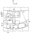
図3に示す如く、プレート12内には、支持部材としての略平板状の支持板22が固定されており、支持板22は、左右方向に垂直に配置されている。支持板22は、レバー14の突出部18Aの上側に配置されており、突出部18Aは、支持板22の右側に突出されている。支持板22には、略直方体形箱状の支持枠22A(図5参照)が一体に設けられており、支持枠22Aの左壁は、支持板22によって形成されている。支持枠22Aは、右側に突出されており、支持枠22Aの下面全体及び後面の左側部分は、開放されている。支持枠22Aの前壁の左右方向中央、及び、支持枠22Aの後壁の左端には、断面矩形状の案内部24が一体に設けられており、一対の案内部24は、それぞれ上下方向に延伸されると共に、前後方向において対向されている。
支持板22の下端部には、規制突起26が一体に設けられており、規制突起26は、右側に突出されている。規制突起26には、断面矩形状の規制溝26Aが形成されており、規制溝26Aは、規制突起26を上下方向に貫通されると共に、右側に開放されている。
支持板22の右側には、規制部としての略T字形板状のロックバー28が設けられており、ロックバー28の上部の前側部分には、略直方体状の突起部28A(図5参照)が一体に設けられている。突起部28Aは、右側に突出されており、ロックバー28の上部の前側部分(突起部28Aを含む)は、支持板22の支持枠22A内に挿入されている。突起部28Aの前面及び後面には、断面矩形状の案内溝28Cが形成されており、一対の案内溝28Cは、それぞれ上下方向に延伸されて突起部28Aを貫通されると共に、前後方向において突起部28Aを挟んで対向されている。案内溝28Cには、支持枠22Aの案内部24が嵌合されており、これにより、ロックバー28(突起部28A)の前後方向及び左右方向への移動が規制されると共に、案内溝28Cが案内部24に案内されて上下方向に移動されることで、ロックバー28が上下方向に移動される。ロックバー28の下部は、支持板22の規制突起26の規制溝26Aに上下方向に移動可能に挿入されており、ロックバー28の下部は、規制溝26Aに前後方向において嵌合されて、前後方向への移動を規制されている。ロックバー28の上部の後側部分には、断面略矩形状の凹部28Bが形成されており、凹部28Bは、左右方向両側、下側及び後側に開放されている。
支持板22(支持枠22Aでもよい)とロックバー28との間には、付勢手段(図示省略)が掛渡されており、ロックバー28は、付勢手段によって下側に付勢されている。このため、レバー14が「P」位置、「R」位置、「N」位置及び「D」位置に配置される際には、付勢手段の付勢力によってロックバー28が下側の規制位置に配置されて、それぞれロックバー28の下端部がレバー14のディテント溝20のP溝20P、R溝20R、N溝20N及びD溝20Dに挿入される。ロックバー28は、付勢手段の付勢力に抗して上側の許可位置に移動可能にされており、ロックバー28は、許可位置に配置されて、下端部がディテント溝20の上側に配置される(図4参照)。
プレート12内には、規制検出機構48(図2参照)が設けられており、規制検出機構48は、ロックバー28の上下方向位置を検出する。
ロックバー28の凹部28B上面の下側には、回転部としての略平板状のカム30が配置されており、カム30には、回転軸32が一体回転可能に貫通されている。回転軸32は、支持板22とプレート12の右壁との間に掛渡されて、左右方向に平行に配置されており、カム30は、回転軸32を中心として、図3の規制方向A及び許可方向Bに回転可能にされている。カム30の回転径寸法は、規制方向Aへ向かうに従い徐々に大きくされており、カム30は、規制方向A側の回転位置に配置されている。
図2に示す如く、回転軸32は、カム30の右側において、ギア34(ウォームホイール)に同軸上に貫通されており、ギア34は、回転軸32と一体回転可能にされている。
プレート12内には、ギア34の後側かつ上側において、駆動機構としてのモータ36が配置されており、モータ36は、プレート12の右壁に固定されている。モータ36の出力軸は、下方に延出されており、モータ36の出力軸には、ウォーム38が同軸上に固定されている。ウォーム38には、ギア34が噛合されており、モータ36が駆動されて、モータ36の出力軸と一体にウォーム38が回転されることで、ギア34が減速されて回転されて、ギア34と一体に回転軸32及びカム30が回転される。
モータ36は、制御装置40に電気的に接続されており、モータ36は、制御装置40の制御により、一方向及び他方向に駆動される。制御装置40には、車両のブレーキ42が電気的に接続されており、乗員によってブレーキ42が操作されることで、車両が制動される。また、制御装置40には、上記シフト検出機構44、操作検出機構46、規制検出機構48及び報知機構(図示省略)が電気的に接続されている。
次に、本実施形態の作用を説明する。
以上の構成のシフトレバー装置10では、レバー14が「P」位置、「R」位置、「N」位置及び「D」位置に配置される際に、付勢手段の付勢力によってロックバー28が規制位置に配置されて、それぞれロックバー28の下端部がレバー14(回動板18の突出部18A)のディテント溝20のP溝20P、R溝20R、N溝20N及びD溝20Dに挿入される。
レバー14が「P」位置に配置される場合(レバー14が「P」位置に配置されることをシフト検出機構44が検出する場合)に、ブレーキ42が操作された状態で、ノブ16のボタンが操作されない際(ボタンが操作されたことを操作検出機構46が検出しない際)には、ロックバー28の下端部がP溝20Pに挿入された状態が維持される。このため、レバー14が「P」位置から後側に回動操作されて、回動板18が前側に回動される際には、P溝20Pの後面がロックバー28の下端部に当接されて、回動板18の前側への回動がロックバー28によって係止されることで、レバー14の「P」位置から後側への回動操作が規制(ロック)される。
一方、レバー14が「P」位置に配置される場合(レバー14が「P」位置に配置されることをシフト検出機構44が検出する場合)に、ブレーキ42が操作された状態で、ノブ16のボタンが操作された際(ボタンが操作されたことを操作検出機構46が検出した際)には、制御装置40の制御により、モータ36が一方向に駆動されて、モータ36の出力軸、ウォーム38、ギア34及び回転軸32が回転されることで、カム30が許可方向Bに回転されて、ロックバー28が付勢手段の付勢力に抗して許可位置に移動され、ロックバー28の下端部がP溝20Pの上側に配置される。このため、レバー14が「P」位置から後側に回動操作されて、回動板18が前側に回動される際には、P溝20Pの後面がロックバー28の下端部に当接されずに、回動板18の前側への回動がロックバー28によって係止されないことで、レバー14の「P」位置から後側への回動操作が許可される。
ノブ16のボタンの操作が解除された際(ボタンが操作されたことを操作検出機構46が検出した状態からボタンが操作されたことを操作検出機構46が検出しない状態になった際)には、制御装置40の制御により、モータ36が他方向に駆動されて、モータ36の出力軸、ウォーム38、ギア34及び回転軸32が回転されることで、カム30が規制方向Aに回転されて、ロックバー28が付勢手段の付勢力によって下側に移動される。このため、レバー14が「P」位置、「R」位置、「N」位置及び「D」位置に配置される際には、ロックバー28が規制位置に配置されて、それぞれロックバー28の下端部がP溝20P、R溝20R、N溝20N及びD溝20Dに挿入される。
レバー14が「R」位置に配置される場合(レバー14が「P」位置に配置されることをシフト検出機構44が検出しない場合)に、ノブ16のボタンが操作されない際(ボタンが操作されたことを操作検出機構46が検出しない際)には、ロックバー28の下端部がR溝20Rに挿入された状態が維持される。このため、レバー14が「R」位置から前側に回動操作されて、回動板18が後側に回動される際には、R溝20Rの前面がロックバー28の下端部に当接されて、回動板18の後側への回動がロックバー28によって係止されることで、レバー14の「R」位置から前側への回動操作が規制される。
一方、レバー14が「R」位置に配置される場合(レバー14が「P」位置に配置されることをシフト検出機構44が検出しない場合)に、ノブ16のボタンが操作された際(ボタンが操作されたことを操作検出機構46が検出した際)には、制御装置40の制御により、モータ36が一方向に駆動されて、モータ36の出力軸、ウォーム38、ギア34及び回転軸32が回転されることで、カム30が許可方向Bに回転されて、ロックバー28が付勢手段の付勢力に抗して許可位置に移動され、ロックバー28の下端部がR溝20Rの上側に配置される。このため、レバー14が「R」位置から前側に回動操作されて、回動板18が後側に回動される際には、R溝20Rの前面がロックバー28の下端部に当接されずに、回動板18の後側への回動がロックバー28によって係止されないことで、レバー14の「R」位置から前側への回動操作が許可される。
また、レバー14が「R」位置から後側に回動操作されて、回動板18が前側に回動される際には、R溝20Rの後面によってロックバー28が付勢手段の付勢力に抗して上側に移動された後に、N溝20Nがロックバー28に到達することで、ロックバー28が付勢手段の付勢力によって下側に移動されて、ロックバー28の下端部がN溝20Nに挿入される。
レバー14が「N」位置に配置される場合(レバー14が「P」位置に配置されることをシフト検出機構44が検出しない場合)に、ノブ16のボタンが操作されない際(ボタンが操作されたことを操作検出機構46が検出しない際)には、ロックバー28の下端部がN溝20Nに挿入された状態が維持される。このため、レバー14が「N」位置から前側に回動操作されて、回動板18が後側に回動される際には、N溝20Nの前面がロックバー28の下端部に当接されて、回動板18の後側への回動がロックバー28によって係止されることで、レバー14の「N」位置から前側への回動操作が規制される。
一方、レバー14が「N」位置に配置される場合(レバー14が「P」位置に配置されることをシフト検出機構44が検出しない場合)に、ノブ16のボタンが操作された際(ボタンが操作されたことを操作検出機構46が検出した際)には、制御装置40の制御により、モータ36が一方向に駆動されて、モータ36の出力軸、ウォーム38、ギア34及び回転軸32が回転されることで、カム30が許可方向Bに回転されて、ロックバー28が付勢手段の付勢力に抗して許可位置に配置され、ロックバー28の下端部がN溝20Nの上側に配置される。このため、レバー14が「N」位置から前側に回動操作されて、回動板18が後側に回動される際には、N溝20Nの前面がロックバー28の下端部に当接されずに、回動板18の後側への回動がロックバー28によって係止されないことで、レバー14の「N」位置から前側への回動操作が許可される。
また、レバー14が「N」位置から後側に回動操作されて、回動板18が前側に回動される際には、ロックバー28が上下方向に移動されない状態で、ディテント溝20のN溝20NからD溝20Dの部分がロックバー28の下端部を通過することで、レバー14の「N」位置から後側への回動操作が許可される。
さらに、レバー14が「D」位置から前側に回動操作されて、回動板18が後側に回動される際には、ロックバー28が上下方向に移動されない状態で、ディテント溝20のD溝20DからN溝20Nの部分がロックバー28の下端部を通過することで、レバー14の「D」位置から前側への回動操作が許可される。
ここで、カム30の回転径寸法が規制方向Aへ向かうに従い徐々に大きくされており、カム30の回転位置が変更されるに従い、ロックバー28が上下方向に移動される。このため、モータ36の駆動によるカム30の回転位置の変更量に対するロックバー28の上下方向への移動量を小さくできて、ロックバー28が規制位置及び許可位置に配置されるためのカム30の回転位置の精度を低くでき、ロックバー28が規制位置及び許可位置に配置されるためのモータ36の出力軸の回転位置の精度を低くできて、モータ36の駆動によりレバー14のシフト位置の変更の規制と許可とを適切に変更できる。
さらに、カム30が回転されることで、ロックバー28が上下方向に移動される。このため、ロックバー28を上下方向に移動させるための部品点数を削減できて、コストを低減できると共に、小型化できる。
また、ディテント溝20の下面(P溝20P、R溝20R、N溝20N及びD溝20Dの下面)がレバー14の回動周方向に沿う同一の湾曲面にされており、ロックバー28の下端部がディテント溝20の下面に当接された際におけるロックバー28の支持板22に対する上下方向位置であるロックバー28の規制位置が一定の位置にされる。このため、ロックバー28の規制位置と許可位置との間での移動ストロークを低減でき、モータ36の駆動によりロックバー28を規制位置及び許可位置に配置する制御装置40の制御を容易にできて、制御装置40の制御によりレバー14のシフト位置の変更の規制と許可とを適切に変更できる。
さらに、モータ36が、一方向に駆動されて、ロックバー28を規制位置から許可位置に移動させるため、ロックバー28の規制位置から許可位置への移動力を大きくできる。このため、例えば乗員からレバー14に回動荷重が入力されて、ディテント溝20の側面(P溝20Pの後面、R溝20Rの前面又はN溝20Nの前面)とロックバー28の下端部との接触圧力が大きくされることで、ディテント溝20の側面とロックバー28の下端部との摩擦力が大きくされて、ロックバー28の移動抵抗が大きい場合でも、ロックバー28を規制位置から許可位置に移動させることができ、レバー14のシフト位置の変更の規制と許可とを適切に変更できる。
また、モータ36が一方向に駆動されて、ロックバー28が規制位置から許可位置に移動される際には、ロックバー28が許可位置に到達したことを規制検出機構48が検出して、制御装置40の制御によりモータ36の駆動が停止される。このため、ロックバー28が支持板22の支持枠22Aの上壁に当接することを抑制でき、ロックバー28が支持枠22Aの上壁に当接することによる当接音の発生を抑制できる。
さらに、モータ36が駆動されて、ロックバー28が規制位置と許可位置とに移動される。このため、ノブ16のボタンをレバー14内(ノブ16内を含む)を介してロックバー28に機械的に連絡する必要がない。これにより、レバー14(ノブ16を含む)を小型化及び異形化できる(例えばレバー14の上側部分を長手方向において湾曲させること等ができる)と共に、例えばノブ16に付加機構(例えばインジケータ)を設置でき、レバー14(ノブ16を含む)のデザインの自由度を向上できる。
また、例えば車両が長時間放置される場合(車両の駐車時等)において、レバー14が「P」位置に配置される状態(レバー14が「P」位置に配置されることをシフト検出機構44が検出する状態)で、ノブ16のボタンがシャットダウン操作(例えばロックバー28が許可位置に移動される上記の場合よりも長時間の操作)された際(ボタンがシャットダウン操作されたことを操作検出機構46が検出した際)には、制御装置40の制御により、モータ36がシャットダウンされる(電源をオフにされる)。このため、ブレーキ42が操作された状態でノブ16のボタンが操作されても、レバー14の「P」位置から後側への回動操作が許可されない。
さらに、モータ36がシャットダウンされた状態で、ノブ16のボタンが待機操作(例えばロックバー28が許可位置に移動される上記の場合よりも長時間の操作)された際(ボタンが待機操作されたことを操作検出機構46が検出した際)には、制御装置40の制御により、モータ36が待機状態(復帰操作待ち状態)にされる。また、モータ36が待機状態にされた際には、制御装置40の制御により、報知機構が乗員にモータ36が待機状態にされたこと(例えばボタンの復帰操作が必要なこと)を報知する。例えば、モータ36が待機状態にされたことを報知機構としての表示機構(車両のインジケータやメータ等)が表示し、又は、報知機構としての発光機構(車両のアンビエントライト等)が所定色で発光する。
そして、モータ36が待機状態にされた状態で、ノブ16のボタンが復帰操作(例えば所定パターンでの複数回の間欠操作)された際(ボタンが復帰操作されたことを操作検出機構46が検出した際)には、制御装置40の制御により、モータ36がシャットダウン状態から復帰される(電源をオンにされる)。このため、ブレーキ42が操作された状態でノブ16のボタンが操作されることで、上述の如くレバー14の「P」位置から後側への回動操作が許可される。また、ボタンの復帰操作は、乗員によって制御装置40に予め入力されている。
以上のように、モータ36がシャットダウンされることで、レバー14の「P」位置からの回動操作が許可されない。これにより、車両が盗難されることを効果的に抑制でき、車両のセキュリティ性を向上できる。
なお、本実施形態では、レバー14にディテント溝20を設けると共に、車体側(プレート12及び支持板22)にロックバー28(モータ36等を含む)を設けた。しかしながら、レバー14にロックバー28(モータ36等を含む)を設けると共に、車体側(プレート12及び支持板22の少なくとも一方)にディテント溝20を設けてもよい。
また、本実施形態では、シフトレバー装置10をフロア式のものにして車室の床部に設置した。しかしながら、シフトレバー装置10を車室のコラムカバーやインストルメントパネルに設置してもよい。
2016年9月12日に出願された日本国特許出願2016-178006号の開示は、その全体が参照により本明細書に取込まれる。
10 シフトレバー装置(シフト装置)
14 レバー(シフト体)
28 ロックバー(規制部)
30 カム(回転部)
36 モータ
14 レバー(シフト体)
28 ロックバー(規制部)
30 カム(回転部)
36 モータ
Claims (6)
- 移動されてシフト位置が変更されるシフト体と、
規制位置に配置されて前記シフト体のシフト位置の変更が規制され、規制位置から許可位置に移動されて前記シフト体のシフト位置の変更が許可される規制部と、
操作可能にされる操作部と、
前記操作部が操作されることで回転位置が変更されて前記規制部が規制位置から許可位置に移動されると共に、回転位置が変更されるに従い前記規制部が移動される回転部と、
を備えるシフト装置。 - 前記回転部の回転径寸法が前記回転部の回転周方向において変更される請求項1記載のシフト装置。
- 移動されてシフト位置が変更されるシフト体と、
規制位置に配置されて前記シフト体のシフト位置の変更が規制され、規制位置から許可位置に移動されて前記シフト体のシフト位置の変更が許可されると共に、規制位置が一定の位置にされる規制部と、
操作されることで前記規制部が規制位置から許可位置に移動される操作部と、
を備えるシフト装置。 - 前記規制部を規制位置に係止する面が前記シフト体の移動方向に沿って配置される係止部を備える請求項3記載のシフト装置。
- 移動されてシフト位置が変更されるシフト体と、
規制位置に配置されて前記シフト体のシフト位置の変更が規制され、規制位置から許可位置に移動されて前記シフト体のシフト位置の変更が許可される規制部と、
操作可能にされる操作部と、
前記操作部が操作されることで駆動されて前記規制部を規制位置から許可位置に移動させるモータと、
を備えるシフト装置。 - 前記規制部が許可位置に移動されたことが検出されて前記モータの駆動が停止される請求項5記載のシフト装置。
Priority Applications (4)
| Application Number | Priority Date | Filing Date | Title |
|---|---|---|---|
| DE112017004578.9T DE112017004578T5 (de) | 2016-09-12 | 2017-08-30 | Schaltvorrichtung |
| CN201780054052.9A CN109661319B (zh) | 2016-09-12 | 2017-08-30 | 换挡装置 |
| JP2018538377A JP6785865B2 (ja) | 2016-09-12 | 2017-08-30 | シフト装置 |
| US16/330,591 US11746891B2 (en) | 2016-09-12 | 2017-08-30 | Shift device |
Applications Claiming Priority (2)
| Application Number | Priority Date | Filing Date | Title |
|---|---|---|---|
| JP2016178006 | 2016-09-12 | ||
| JP2016-178006 | 2016-09-12 |
Publications (1)
| Publication Number | Publication Date |
|---|---|
| WO2018047701A1 true WO2018047701A1 (ja) | 2018-03-15 |
Family
ID=61561505
Family Applications (1)
| Application Number | Title | Priority Date | Filing Date |
|---|---|---|---|
| PCT/JP2017/031252 Ceased WO2018047701A1 (ja) | 2016-09-12 | 2017-08-30 | シフト装置 |
Country Status (5)
| Country | Link |
|---|---|
| US (1) | US11746891B2 (ja) |
| JP (1) | JP6785865B2 (ja) |
| CN (1) | CN109661319B (ja) |
| DE (1) | DE112017004578T5 (ja) |
| WO (1) | WO2018047701A1 (ja) |
Cited By (3)
| Publication number | Priority date | Publication date | Assignee | Title |
|---|---|---|---|---|
| KR20200034341A (ko) * | 2018-09-21 | 2020-03-31 | 에스엘 주식회사 | 차량용 변속 장치 |
| KR20200079951A (ko) * | 2018-12-26 | 2020-07-06 | 에스엘 주식회사 | 차량용 변속 장치 |
| US20220325791A1 (en) * | 2021-04-08 | 2022-10-13 | Kuster North America, Inc. | Gear seeking polystable shifter |
Families Citing this family (4)
| Publication number | Priority date | Publication date | Assignee | Title |
|---|---|---|---|---|
| KR102289765B1 (ko) * | 2017-03-30 | 2021-08-13 | 에스엘 주식회사 | 변속 장치 및 시스템 |
| JP7088485B2 (ja) * | 2018-01-05 | 2022-06-21 | 株式会社東海理化電機製作所 | シフト装置 |
| US11635139B2 (en) | 2021-03-29 | 2023-04-25 | Kuster North America, Inc. | Plunger lock mechanism such as for restricting shifter motion |
| US11603926B2 (en) * | 2021-04-08 | 2023-03-14 | Kuster North America, Inc. | Gear seeking polystable shifter |
Citations (3)
| Publication number | Priority date | Publication date | Assignee | Title |
|---|---|---|---|---|
| US20040229726A1 (en) * | 2003-05-15 | 2004-11-18 | Wilde Scott D. | Shifter with gear position indicator |
| JP2008023078A (ja) * | 2006-07-21 | 2008-02-07 | Matsushita Electric Works Ltd | 引出しロック機構付キャビネット |
| JP2011110990A (ja) * | 2009-11-25 | 2011-06-09 | Tokai Rika Co Ltd | シフト操作規制装置 |
Family Cites Families (23)
| Publication number | Priority date | Publication date | Assignee | Title |
|---|---|---|---|---|
| DE4406598C2 (de) * | 1994-03-01 | 1996-10-31 | Daimler Benz Ag | Schalteinrichtung für ein selbsttätig schaltendes Wechselgetriebe mit einer mechanischen Sperre für den Rückwärtsgang in einem Kraftfahrzeug |
| US5662001A (en) * | 1996-04-08 | 1997-09-02 | Dura Automotive Services | Manual shifter and ignition interlock |
| DE102007024030B4 (de) * | 2007-05-22 | 2011-01-05 | Zf Friedrichshafen Ag | Betätigungseinrichtung mit Sperrvorrichtung |
| US7832302B2 (en) * | 2008-02-29 | 2010-11-16 | Dura Global Technologies, Llc | Shift-by-wire shifter with default to park |
| JP5142285B2 (ja) * | 2008-03-27 | 2013-02-13 | 現代自動車株式会社 | 自動変速機付き車両の変速レバーロック装置 |
| US8196491B2 (en) * | 2008-04-30 | 2012-06-12 | Allison Transmission, Inc. | Shift selector apparatus |
| JP5823243B2 (ja) | 2011-10-13 | 2015-11-25 | 株式会社東海理化電機製作所 | シフト装置 |
| JP5823244B2 (ja) * | 2011-10-13 | 2015-11-25 | 株式会社東海理化電機製作所 | シフト装置 |
| EP2815287B1 (en) * | 2012-02-16 | 2021-05-05 | Kostal of America | Rotary selector switch and related systems and methods |
| JP6278594B2 (ja) * | 2012-12-07 | 2018-02-14 | 株式会社東海理化電機製作所 | シフト装置 |
| KR101438307B1 (ko) * | 2013-02-27 | 2014-09-15 | 대성전기공업 주식회사 | 차량용 변속 레인지 스위치 장치 |
| JP6013970B2 (ja) * | 2013-05-21 | 2016-10-25 | 株式会社東海理化電機製作所 | シフト操作装置 |
| KR20140141248A (ko) * | 2013-05-31 | 2014-12-10 | 에스엘 주식회사 | 변속기의 초기 모드 복귀 장치 |
| DE102013224494A1 (de) * | 2013-11-29 | 2015-06-03 | Zf Friedrichshafen Ag | Vorrichtung und Verfahren zum Einstellen einer Bewegung eines Bedienelements für ein Automatikgetriebe eines Fahrzeugs sowie Schaltvorrichtung zum Schalten eines Automatikgetriebes eines Fahrzeugs |
| JP6239446B2 (ja) * | 2014-06-13 | 2017-11-29 | 株式会社東海理化電機製作所 | シフト装置 |
| DE102015012769A1 (de) * | 2014-10-29 | 2016-05-04 | U-Shin Ltd. | Schaltvorrichtung |
| JP6379014B2 (ja) * | 2014-11-13 | 2018-08-22 | 株式会社東海理化電機製作所 | シフト装置 |
| JP6407745B2 (ja) * | 2015-02-05 | 2018-10-17 | 株式会社東海理化電機製作所 | シフト装置 |
| JP6495704B2 (ja) | 2015-03-20 | 2019-04-03 | トクデン株式会社 | 誘導加熱システム |
| EP3073155B1 (en) * | 2015-03-23 | 2017-06-14 | FCA Italy S.p.A. | A device for inhibiting selection of one or more operative positions of a selector of an automatically operated gearbox, for example a parking position |
| KR101637949B1 (ko) * | 2015-04-30 | 2016-07-08 | 경창산업주식회사 | 차량용 변속제어 레버 장치 |
| WO2017004126A1 (en) * | 2015-06-30 | 2017-01-05 | Dura Operating Llc | Vehicle shift lever assembly |
| JP6419978B2 (ja) * | 2015-09-24 | 2018-11-07 | コングスベルグ オートモーティヴ アクチボラゲット | 車両のトランスミッションのためのギアシフトアセンブリ |
-
2017
- 2017-08-30 CN CN201780054052.9A patent/CN109661319B/zh active Active
- 2017-08-30 US US16/330,591 patent/US11746891B2/en active Active
- 2017-08-30 WO PCT/JP2017/031252 patent/WO2018047701A1/ja not_active Ceased
- 2017-08-30 DE DE112017004578.9T patent/DE112017004578T5/de not_active Withdrawn
- 2017-08-30 JP JP2018538377A patent/JP6785865B2/ja active Active
Patent Citations (3)
| Publication number | Priority date | Publication date | Assignee | Title |
|---|---|---|---|---|
| US20040229726A1 (en) * | 2003-05-15 | 2004-11-18 | Wilde Scott D. | Shifter with gear position indicator |
| JP2008023078A (ja) * | 2006-07-21 | 2008-02-07 | Matsushita Electric Works Ltd | 引出しロック機構付キャビネット |
| JP2011110990A (ja) * | 2009-11-25 | 2011-06-09 | Tokai Rika Co Ltd | シフト操作規制装置 |
Cited By (6)
| Publication number | Priority date | Publication date | Assignee | Title |
|---|---|---|---|---|
| KR20200034341A (ko) * | 2018-09-21 | 2020-03-31 | 에스엘 주식회사 | 차량용 변속 장치 |
| KR102611276B1 (ko) * | 2018-09-21 | 2023-12-07 | 에스엘 주식회사 | 차량용 변속 장치 |
| KR20200079951A (ko) * | 2018-12-26 | 2020-07-06 | 에스엘 주식회사 | 차량용 변속 장치 |
| KR102584378B1 (ko) * | 2018-12-26 | 2023-10-04 | 에스엘 주식회사 | 차량용 변속 장치 |
| US20220325791A1 (en) * | 2021-04-08 | 2022-10-13 | Kuster North America, Inc. | Gear seeking polystable shifter |
| US11906044B2 (en) * | 2021-04-08 | 2024-02-20 | Kuster North America, Inc. | Gear seeking polystable shifter |
Also Published As
| Publication number | Publication date |
|---|---|
| CN109661319B (zh) | 2022-08-16 |
| CN109661319A (zh) | 2019-04-19 |
| JP6785865B2 (ja) | 2020-11-18 |
| US20200149626A1 (en) | 2020-05-14 |
| JPWO2018047701A1 (ja) | 2019-06-24 |
| DE112017004578T5 (de) | 2019-06-06 |
| US11746891B2 (en) | 2023-09-05 |
Similar Documents
| Publication | Publication Date | Title |
|---|---|---|
| JP6785865B2 (ja) | シフト装置 | |
| JP6594708B2 (ja) | シフト装置 | |
| JP5813731B2 (ja) | シフト装置 | |
| JP6379014B2 (ja) | シフト装置 | |
| JP7409601B2 (ja) | シフト装置 | |
| JP6683585B2 (ja) | シフト装置 | |
| WO2017122642A1 (ja) | シフト装置 | |
| US11306816B2 (en) | Shift device | |
| JP6199271B2 (ja) | シフト装置 | |
| JP2019119352A (ja) | シフト装置 | |
| WO2016084619A1 (ja) | シフト装置 | |
| JP2019043409A (ja) | シフト装置 | |
| JP7215665B2 (ja) | シフト装置 | |
| JP6129661B2 (ja) | シフト装置 | |
| JP2019064329A (ja) | シフト装置 | |
| JP6689682B2 (ja) | シフト装置 | |
| JP6199165B2 (ja) | シフト装置 | |
| JP6689739B2 (ja) | シフト装置 | |
| JP2017114170A (ja) | シフト装置 | |
| JP2017218095A (ja) | シフト装置 | |
| JP6239446B2 (ja) | シフト装置 | |
| WO2019059007A1 (ja) | 車両のシフト装置 | |
| WO2018163762A1 (ja) | シフト装置 | |
| JP2018058462A (ja) | シフト装置 | |
| JP2018167836A (ja) | シフト装置 |
Legal Events
| Date | Code | Title | Description |
|---|---|---|---|
| 121 | Ep: the epo has been informed by wipo that ep was designated in this application |
Ref document number: 17848641 Country of ref document: EP Kind code of ref document: A1 |
|
| ENP | Entry into the national phase |
Ref document number: 2018538377 Country of ref document: JP Kind code of ref document: A |
|
| 122 | Ep: pct application non-entry in european phase |
Ref document number: 17848641 Country of ref document: EP Kind code of ref document: A1 |