WO2018037686A1 - 超純水製造装置 - Google Patents
超純水製造装置 Download PDFInfo
- Publication number
- WO2018037686A1 WO2018037686A1 PCT/JP2017/022615 JP2017022615W WO2018037686A1 WO 2018037686 A1 WO2018037686 A1 WO 2018037686A1 JP 2017022615 W JP2017022615 W JP 2017022615W WO 2018037686 A1 WO2018037686 A1 WO 2018037686A1
- Authority
- WO
- WIPO (PCT)
- Prior art keywords
- membrane
- membrane module
- ultrafiltration membrane
- ultrapure water
- ultrafiltration
- Prior art date
- Legal status (The legal status is an assumption and is not a legal conclusion. Google has not performed a legal analysis and makes no representation as to the accuracy of the status listed.)
- Ceased
Links
Images

Classifications
-
- B—PERFORMING OPERATIONS; TRANSPORTING
- B01—PHYSICAL OR CHEMICAL PROCESSES OR APPARATUS IN GENERAL
- B01D—SEPARATION
- B01D61/00—Processes of separation using semi-permeable membranes, e.g. dialysis, osmosis or ultrafiltration; Apparatus, accessories or auxiliary operations specially adapted therefor
- B01D61/14—Ultrafiltration; Microfiltration
- B01D61/145—Ultrafiltration
- B01D61/146—Ultrafiltration comprising multiple ultrafiltration steps
-
- B—PERFORMING OPERATIONS; TRANSPORTING
- B01—PHYSICAL OR CHEMICAL PROCESSES OR APPARATUS IN GENERAL
- B01D—SEPARATION
- B01D61/00—Processes of separation using semi-permeable membranes, e.g. dialysis, osmosis or ultrafiltration; Apparatus, accessories or auxiliary operations specially adapted therefor
- B01D61/14—Ultrafiltration; Microfiltration
- B01D61/18—Apparatus therefor
-
- B—PERFORMING OPERATIONS; TRANSPORTING
- B01—PHYSICAL OR CHEMICAL PROCESSES OR APPARATUS IN GENERAL
- B01D—SEPARATION
- B01D61/00—Processes of separation using semi-permeable membranes, e.g. dialysis, osmosis or ultrafiltration; Apparatus, accessories or auxiliary operations specially adapted therefor
- B01D61/58—Multistep processes
-
- B—PERFORMING OPERATIONS; TRANSPORTING
- B01—PHYSICAL OR CHEMICAL PROCESSES OR APPARATUS IN GENERAL
- B01D—SEPARATION
- B01D63/00—Apparatus in general for separation processes using semi-permeable membranes
- B01D63/02—Hollow fibre modules
-
- B—PERFORMING OPERATIONS; TRANSPORTING
- B01—PHYSICAL OR CHEMICAL PROCESSES OR APPARATUS IN GENERAL
- B01D—SEPARATION
- B01D69/00—Semi-permeable membranes for separation processes or apparatus characterised by their form, structure or properties; Manufacturing processes specially adapted therefor
- B01D69/08—Hollow fibre membranes
-
- C—CHEMISTRY; METALLURGY
- C02—TREATMENT OF WATER, WASTE WATER, SEWAGE, OR SLUDGE
- C02F—TREATMENT OF WATER, WASTE WATER, SEWAGE, OR SLUDGE
- C02F1/00—Treatment of water, waste water, or sewage
- C02F1/44—Treatment of water, waste water, or sewage by dialysis, osmosis or reverse osmosis
- C02F1/444—Treatment of water, waste water, or sewage by dialysis, osmosis or reverse osmosis by ultrafiltration or microfiltration
-
- B—PERFORMING OPERATIONS; TRANSPORTING
- B01—PHYSICAL OR CHEMICAL PROCESSES OR APPARATUS IN GENERAL
- B01D—SEPARATION
- B01D2315/00—Details relating to the membrane module operation
- B01D2315/08—Fully permeating type; Dead-end filtration
-
- B—PERFORMING OPERATIONS; TRANSPORTING
- B01—PHYSICAL OR CHEMICAL PROCESSES OR APPARATUS IN GENERAL
- B01D—SEPARATION
- B01D2317/00—Membrane module arrangements within a plant or an apparatus
- B01D2317/02—Elements in series
-
- B—PERFORMING OPERATIONS; TRANSPORTING
- B01—PHYSICAL OR CHEMICAL PROCESSES OR APPARATUS IN GENERAL
- B01D—SEPARATION
- B01D2317/00—Membrane module arrangements within a plant or an apparatus
- B01D2317/02—Elements in series
- B01D2317/025—Permeate series
-
- B—PERFORMING OPERATIONS; TRANSPORTING
- B01—PHYSICAL OR CHEMICAL PROCESSES OR APPARATUS IN GENERAL
- B01D—SEPARATION
- B01D2317/00—Membrane module arrangements within a plant or an apparatus
- B01D2317/04—Elements in parallel
-
- B—PERFORMING OPERATIONS; TRANSPORTING
- B01—PHYSICAL OR CHEMICAL PROCESSES OR APPARATUS IN GENERAL
- B01D—SEPARATION
- B01D2317/00—Membrane module arrangements within a plant or an apparatus
- B01D2317/08—Use of membrane modules of different kinds
-
- C—CHEMISTRY; METALLURGY
- C02—TREATMENT OF WATER, WASTE WATER, SEWAGE, OR SLUDGE
- C02F—TREATMENT OF WATER, WASTE WATER, SEWAGE, OR SLUDGE
- C02F1/00—Treatment of water, waste water, or sewage
- C02F1/30—Treatment of water, waste water, or sewage by irradiation
- C02F1/32—Treatment of water, waste water, or sewage by irradiation with ultraviolet light
-
- C—CHEMISTRY; METALLURGY
- C02—TREATMENT OF WATER, WASTE WATER, SEWAGE, OR SLUDGE
- C02F—TREATMENT OF WATER, WASTE WATER, SEWAGE, OR SLUDGE
- C02F1/00—Treatment of water, waste water, or sewage
- C02F1/42—Treatment of water, waste water, or sewage by ion-exchange
-
- C—CHEMISTRY; METALLURGY
- C02—TREATMENT OF WATER, WASTE WATER, SEWAGE, OR SLUDGE
- C02F—TREATMENT OF WATER, WASTE WATER, SEWAGE, OR SLUDGE
- C02F1/00—Treatment of water, waste water, or sewage
- C02F1/42—Treatment of water, waste water, or sewage by ion-exchange
- C02F2001/427—Treatment of water, waste water, or sewage by ion-exchange using mixed beds
-
- C—CHEMISTRY; METALLURGY
- C02—TREATMENT OF WATER, WASTE WATER, SEWAGE, OR SLUDGE
- C02F—TREATMENT OF WATER, WASTE WATER, SEWAGE, OR SLUDGE
- C02F2103/00—Nature of the water, waste water, sewage or sludge to be treated
- C02F2103/02—Non-contaminated water, e.g. for industrial water supply
- C02F2103/04—Non-contaminated water, e.g. for industrial water supply for obtaining ultra-pure water
-
- C—CHEMISTRY; METALLURGY
- C02—TREATMENT OF WATER, WASTE WATER, SEWAGE, OR SLUDGE
- C02F—TREATMENT OF WATER, WASTE WATER, SEWAGE, OR SLUDGE
- C02F2201/00—Apparatus for treatment of water, waste water or sewage
- C02F2201/002—Construction details of the apparatus
- C02F2201/006—Cartridges
-
- C—CHEMISTRY; METALLURGY
- C02—TREATMENT OF WATER, WASTE WATER, SEWAGE, OR SLUDGE
- C02F—TREATMENT OF WATER, WASTE WATER, SEWAGE, OR SLUDGE
- C02F2209/00—Controlling or monitoring parameters in water treatment
- C02F2209/40—Liquid flow rate
-
- C—CHEMISTRY; METALLURGY
- C02—TREATMENT OF WATER, WASTE WATER, SEWAGE, OR SLUDGE
- C02F—TREATMENT OF WATER, WASTE WATER, SEWAGE, OR SLUDGE
- C02F2301/00—General aspects of water treatment
- C02F2301/08—Multistage treatments, e.g. repetition of the same process step under different conditions
Definitions
- the present invention relates to an ultrapure water production apparatus.
- ultrapure water from which impurities are highly removed is used for various purposes such as a cleaning process.
- Ultrapure water is generally produced by sequentially treating raw water (river water, groundwater, industrial water, etc.) with a pretreatment system, a primary pure water system, and a secondary pure water system (subsystem).
- a membrane separation device such as an ultrafiltration membrane device is provided at the last stage in order to remove fine particles contained in ultrapure water. Since the fine particles contained in ultrapure water cause a direct decrease in device yield, the size (particle diameter) and number (concentration) are strictly controlled. Therefore, in order to reduce the number of fine particles in ultrapure water, a configuration in which a plurality of membrane separation devices are connected in series has been proposed (see, for example, Patent Documents 1 to 4).
- JP 2004-283710 A JP 2003-190951 A JP-A-10-216721 JP-A-4-338221
- an object of the present invention is to provide an ultrapure water production apparatus for producing ultrapure water in which the number of fine particles is sufficiently reduced.
- the ultrapure water production apparatus of the present invention includes an ultrafiltration membrane apparatus.
- the ultrafiltration membrane device has a plurality of ultrafiltration membranes connected in series, and the plurality of ultrafiltration membranes are a first ultrafiltration membrane and a plurality of ultrafiltration membranes.
- the second ultrafiltration membrane which is located on the most downstream side and has different filtration performance from the first ultrafiltration membrane, is included.
- the ultrafiltration membrane device has a plurality of ultrafiltration membrane modules connected in series, and the plurality of ultrafiltration membrane modules includes a first ultrafiltration membrane module and a plurality of ultrafiltration membrane modules. It includes a second ultrafiltration membrane module which is located on the most downstream side of the outer filtration membrane module and has a filtration performance different from that of the first ultrafiltration membrane module.
- the ultrapure water manufacturing apparatus which manufactures the ultrapure water in which the number of fine particles was fully reduced can be provided.
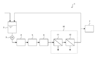
- FIG. 1 is a schematic configuration diagram of an ultrapure water production apparatus according to an embodiment of the present invention.
- the structure of the illustrated ultrapure water production apparatus is merely an example, and does not limit the present invention.
- the ultrapure water production apparatus 1 includes a primary pure water tank 2, a pump 3, a heat exchanger 4, an ultraviolet oxidizer 5, a non-regenerative mixed bed ion exchanger (cartridge polisher) 6, an ultrafiltration unit. (UF) membrane device 10. These constitute a secondary pure water system (sub-system), and produce primary ultra pure water by sequentially treating primary pure water produced by the primary pure water system (not shown), and use the ultra pure water. The point 7 is supplied.
- the treated water (primary pure water) stored in the primary pure water tank 2 is sent out by the pump 3 and supplied to the heat exchanger 4.
- the water to be treated passes through the heat exchanger 4 and is adjusted in temperature, and then supplied to the ultraviolet oxidizer 5, where the total organic carbon (TOC) in the water to be treated is decomposed by irradiation with ultraviolet rays.
- TOC total organic carbon
- metal or the like in the water to be treated is removed by ion exchange in the cartridge polisher 6, and fine particles in the water to be treated are removed in the UF membrane device 10.
- a part of the ultrapure water obtained in this way is supplied to the use point 7 and the rest is returned to the primary pure water tank 2.
- Primary pure water is supplied to the primary pure water tank 2 from a primary pure water system (not shown) as needed.
- the pump 3 As the primary pure water tank 2, the pump 3, the heat exchanger 4, the ultraviolet oxidizer 5, and the cartridge polisher 6, those generally used in the sub-system of the ultrapure water production apparatus can be used. Therefore, description of these detailed structures is abbreviate
- the UF membrane device 10 has two UF membrane modules 11 and 12 connected in series.
- Each of the UF membrane modules 11 and 12 is filled with a bundle of many hollow fiber UF membranes (hereinafter also simply referred to as “hollow fiber membranes”) in a cylindrical casing.
- This is an external pressure type hollow fiber membrane module that supplies permeated water from the inside.
- each UF membrane module 11 and 12 supplies the to-be-processed water parallel to the membrane surface of a hollow fiber membrane as a filtration method, and discharges a part of to-be-processed water which does not permeate
- the first UF membrane module 11 and the second UF membrane module 12 are filled with UF membranes having different filtration performances.
- the UF membrane (second UF membrane) filled in the second UF membrane module 12 is more permeable flux than the UF membrane (first UF membrane) filled in the first UF membrane module 11. It is a membrane that has a large (permeation area per unit membrane and permeate flow rate per unit pressure) and is easy to pass water.
- the UF membrane filled in the second UF membrane module 12 is a loose membrane having a higher molecular weight cut-off than the UF membrane filled in the first UF membrane module. In the second UF membrane module 12, the effects of the larger permeation flux of the UF membrane and the larger fractional molecular weight will be described later.
- the first UF membrane module 11 an appropriate one can be appropriately selected according to the size (particle size) of the fine particles to be removed, and the configuration is not particularly limited.
- those filled with a UF membrane having a molecular weight cut-off of 4000 to 6000 are preferably used, thereby removing fine particles having a particle size of 10 nm or more (hereinafter referred to as “target fine particles”). It becomes possible.
- the material of the UF membrane to be filled is not particularly limited. However, as will be described later, a material with less elution from the membrane itself is preferable, and polysulfone is preferable.
- Examples of the first UF membrane module 11 include UF membrane modules manufactured by Asahi Kasei Corporation (product number: OLT-6036H) and Nitto Denko Corporation (product number: NTU-3306-K6R). All of these are filled with a polysulfone hollow fiber membrane having a molecular weight cut-off of 6000.
- the recovery rate of the first UF membrane module 11 is preferably as high as possible, but is preferably set to be about 95% in consideration of the deposition of fine particles on the membrane surface.
- the second UF membrane module 12 only needs to be filled with a UF membrane having a larger permeation flux or a higher molecular weight cut off than the UF membrane filled in the first UF membrane module 11.
- a UF membrane having a molecular weight cut off of 100,000 to 400,000 can be used, and the material thereof is preferably polysulfone as in the first UF membrane module 11.
- the second UF membrane module 12 include a UF membrane module manufactured by Asahi Kasei Corporation (product number: FGT-6016H). This is filled with a polysulfone hollow fiber membrane having a molecular weight cut off of 100,000.
- the second UF membrane module 12 is filled with a UF membrane having a fractional molecular weight of 6000.
- the above-mentioned UF membrane module manufactured by Asahi Kasei Corporation or Nitto Denko Corporation can be used.
- the second UF membrane module 12 treated water (permeated water) of the first UF membrane module 11 from which fine particles have been sufficiently removed is supplied as treated water, and therefore the first UF membrane module 11.
- the processing load is small, and there is less concern about clogging due to the accumulation of fine particles on the film surface. Therefore, the recovery rate of the second UF membrane module 12 is preferably as high as possible, and may be 95% or more, for example.
- the pore size of the UF membrane is not completely uniform and has a width before and after the pore size corresponding to the molecular weight cut off, so that the particle size of the fine particles that can be removed by the UF membrane also has a width.
- the rejection rate is not necessarily 100%. Therefore, when a plurality of UF membrane modules are connected in series, better treated water quality (number of fine particles) can be obtained compared to the case of a single UF membrane module even if they are filled with UF membranes having the same filtration performance. Expected to be.
- the two UF membrane modules 11 and 12 are not filled with the UF membrane having the same filtration performance, but the second UF membrane module 12 on the downstream side A UF membrane having a filtration performance different from that of one UF membrane, for example, a UF membrane having a larger permeation flux or fractional molecular weight is packed.
- fine particles generated from the UF membrane module itself located at the most downstream side among the plurality of UF membrane modules connected in series module-derived fine particles
- the present inventors manufactured ultrapure water using the ultrapure water manufacturing apparatus shown in FIG. 1, and measured the quality of the treated water. Specifically, the number (concentration) of target fine particles (fine particles having a particle diameter of 10 nm or more) contained in the treated water (permeated water) of each UF membrane module of the UF membrane device was measured.
- both UF membrane modules filled with a polysulfone UF membrane having a molecular weight cut off of 6000 are used.
- Two types of UF membrane modules were prepared. The permeation flow rate of each UF membrane module was 15 m 3 / h.
- the number of fine particles in the permeated water was calculated by the direct microscopic method (SEM method) shown below. That is, the permeated water of each UF membrane module is passed through a particulate trapping device having a filtration membrane to capture the particulates, and the number and particle size of the particulates captured on the filtration membrane are determined using a scanning electron microscope (SEM). The number (concentration) of the target fine particles was calculated.
- SEM method direct microscopic method
- Table 1 shows the measurement results of the number of fine particles in the permeated water for two types of UF membrane modules.
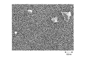
- FIG. 2 shows an example of an SEM photograph of fine particles contained in the permeated water of the second UF membrane module.
- the permeated water of the second UF membrane module contains fine particles having a particle size of 100 nm or more, which is considerably larger than the size corresponding to the molecular weight cut off of the UF membrane of each UF membrane module. It was. Since most of the target fine particles (for example, 100 to 1000 particles / ml) contained in the water to be treated are removed by the first UF membrane module, the particle size in the permeated water of the second UF membrane module is 100 nm or more. It is unlikely that the fine particles were originally contained in the water to be treated, and it is highly likely that the fine particles were generated from the UF membrane module itself.
- the desired treated water quality specifically, the number of fine particles having a particle diameter of 10 nm or more when evaluated by the direct microscopic method described above is less than 10 / ml, preferably less than 5 / ml,
- the module-derived fine particles contained in the treated water it is necessary to reduce the fine particles generated from the UF membrane module located on the most downstream side among the plurality of UF membrane modules connected in series.
- the particle removal performance of the last-stage UF membrane module only needs to be such that large particles of 100 nm or more generated from the preceding UF membrane module can be removed.
- the second UF membrane module 12 on the downstream side has a permeation flux higher than that of the UF membrane filled in the first UF membrane module 11 on the upstream side. It is packed with a large UF membrane, particularly with a high molecular weight cut-off. Since the second UF membrane module 12 can pass water at a larger flow rate than the first UF membrane module 11, fine particles generated from the second UF membrane module 12 itself can be easily removed from the system during cleaning. Can be discharged. Therefore, the thing derived from a module among the fine particles contained in ultrapure water can be reduced.
- the number of fine particles in ultrapure water can be sufficiently reduced, and a desired treated water quality can be obtained.
- the possibility of water flow at a larger flow rate with respect to the second UF membrane module 12 is advantageous in that the cost can be reduced by shortening the cleaning process. That is, since the adhesion of fine particles is unavoidable during the manufacture of the UF membrane module, at least when the apparatus is started up, cleaning with a large amount of ultrapure water (or pure water) is required until the desired treated water quality is obtained.
- the second UF membrane module 12 of the present embodiment fine particles generated from the second UF membrane module 12 can be easily discharged out of the system by improving the cleaning effect described above. The time and cost for this cleaning can be greatly reduced.
- the second UF membrane module 12 is washed in advance with a large flow rate, and the generation of fine particles derived from the module is reduced as much as possible, and then the flow rate is smaller (for example, the same flow rate as the first UF membrane module 11 flows).
- the flow rate is smaller (for example, the same flow rate as the first UF membrane module 11 flows).
- FIG. 3 by connecting a plurality of first UF membrane modules 11 in parallel and connecting them in series to a second UF membrane module 12, a plurality of first UF membrane modules 11 The permeated water may be supplied to the second UF membrane module 12.
- the second UF membrane module 12 may be an internal pressure type UF membrane module from the viewpoint of suppressing the occurrence of such problems.
- the second UF membrane module 12 is less likely to be clogged even if the recovery rate is set high, so a dead-end method that filters the entire amount of water to be treated is adopted as a filtration method. May be.
- each UF membrane module is filled with UF membranes having different fractional molecular weights or permeation fluxes, and the permeate flow rate per unit pressure of each UF membrane module is changed, thereby filtering each UF membrane module.
- the method of changing the filtration performance is not limited to this.
- each UF membrane module can be changed by changing the permeate flow rate per unit pressure of each UF membrane module by filling UF membranes with the same fractional molecular weight at different filling rates or changing the thickness and material of the membrane. The filtration performance can be changed.
- the present invention is not limited to this, and three or more UF membrane modules are included.
- the present invention can also be applied when connected in series.
- three UF membrane modules it is conceivable to add one UF membrane module to the two UF membrane modules shown in FIG.
- a UF membrane module filled with a UF membrane having the same filtration performance as that of the first UF membrane module is inserted between the first UF membrane module and the second UF membrane module.
- it can be added upstream of the first UF membrane module.
- a hollow fiber type microfiltration membrane module may be added downstream of the plurality of UF membrane modules.
Landscapes
- Chemical & Material Sciences (AREA)
- Engineering & Computer Science (AREA)
- Water Supply & Treatment (AREA)
- Chemical Kinetics & Catalysis (AREA)
- Life Sciences & Earth Sciences (AREA)
- Hydrology & Water Resources (AREA)
- Environmental & Geological Engineering (AREA)
- Organic Chemistry (AREA)
- Separation Using Semi-Permeable Membranes (AREA)
Abstract
超純水製造装置1は、限外ろ過膜装置10を備えている。限外ろ過膜装置10は、直列に接続された複数の限外ろ過膜11,12を有し、複数の限外ろ過膜11,12は、第1の限外ろ過膜11と、複数の限外ろ過膜11,12のうち最も下流側に位置し、第1の限外ろ過膜11とはろ過性能が異なる第2の限外ろ過膜12とを含んでいる。
Description
本発明は、超純水製造装置に関する。
半導体デバイスや液晶デバイスの製造プロセスでは、洗浄工程など様々な用途に、不純物が高度に除去された超純水が使用されている。超純水は、一般に、原水(河川水、地下水、工業用水など)を、前処理システム、一次純水システム、および二次純水システム(サブシステム)で順次処理することにより製造されている。
多くのサブシステムでは、その最後段に、超純水に含まれる微粒子を除去するために、限外ろ過膜装置などの膜分離装置が設けられている。超純水に含まれる微粒子は、デバイスの歩留まりを低下させる直接の原因となるため、そのサイズ(粒径)および個数(濃度)が厳しく管理されている。そのため、超純水中の微粒子数を低減するために、複数の膜分離装置が直列に接続された構成が提案されている(例えば、特許文献1~4参照)。
近年の半導体デバイスの急速な高集積化・微細化に伴い、管理すべき微粒子のサイズおよび個数の要求はますます高まっている。例えば、国際半導体技術ロードマップ(ITRS)によれば、超純水に含まれる微粒子として、粒径が10nm以上の微粒子を1個/ml以下に管理することが求められている。しかしながら、特許文献1~4に記載の構成では、このような要求を満足し得る処理水質が得られていないのが実情である。
そこで、本発明の目的は、微粒子数が十分に低減された超純水を製造する超純水製造装置を提供することである。
上述した目的を達成するために、本発明の超純水製造装置は、限外ろ過膜装置を備えている。一態様では、限外ろ過膜装置が、直列に接続された複数の限外ろ過膜を有し、複数の限外ろ過膜が、第1の限外ろ過膜と、複数の限外ろ過膜のうち最も下流側に位置し、第1の限外ろ過膜とはろ過性能が異なる第2の限外ろ過膜とを含んでいる。他の態様では、限外ろ過膜装置が、直列に接続された複数の限外ろ過膜モジュールを有し、複数の限外ろ過膜モジュールが、第1の限外ろ過膜モジュールと、複数の限外ろ過膜モジュールのうち最も下流側に位置し、第1の限外ろ過膜モジュールとはろ過性能が異なる第2の限外ろ過膜モジュールとを含んでいる。
以上、本発明によれば、微粒子数が十分に低減された超純水を製造する超純水製造装置を提供することができる。
以下、図面を参照して、本発明の実施の形態について説明する。
図1は、本発明の一実施形態に係る超純水製造装置の概略構成図である。なお、図示した超純水製造装置の構成は、単なる一例であり、本発明を制限するものではない。
超純水製造装置1は、一次純水タンク2と、ポンプ3と、熱交換器4と、紫外線酸化装置5と、非再生型混床式イオン交換装置(カートリッジポリッシャー)6と、限外ろ過(UF)膜装置10とを有している。これらは、二次純水システム(サブシステム)を構成し、一次純水システム(図示せず)で製造された一次純水を順次処理して超純水を製造し、その超純水をユースポイント7に供給するものである。
一次純水タンク2に貯留された被処理水(一次純水)は、ポンプ3により送出され、熱交換器4に供給される。被処理水は、熱交換器4を通過して温度調節された後、紫外線酸化装置5に供給され、そこで、紫外線の照射により、被処理水中の全有機炭素(TOC)が分解される。その後、カートリッジポリッシャー6において、イオン交換処理により被処理水中の金属などが除去され、UF膜装置10において、被処理水中の微粒子が除去される。こうして得られた超純水は、一部がユースポイント7に供給され、残りが一次純水タンク2に返送するようになっている。一次純水タンク2には、必要に応じて、一次純水システム(図示せず)から一次純水が供給される。
一次純水タンク2、ポンプ3、熱交換器4、紫外線酸化装置5、およびカートリッジポリッシャー6としては、超純水製造装置のサブシステムにおいて一般的に用いられているものを使用することができる。そのため、これらの詳細な構成の説明は省略し、以下では、UF膜装置10の詳細な構成について説明する。
UF膜装置10は、直列に接続された2つのUF膜モジュール11,12を有している。各UF膜モジュール11,12は、円筒状のケーシング内に多数の中空糸状のUF膜(以下、単に「中空糸膜」ともいう)が束ねられて充填され、中空糸膜の外側から被処理水を供給して内側から透過水を取り出す外圧型の中空糸膜モジュールである。また、各UF膜モジュール11,12は、ろ過方法として、被処理水を中空糸膜の膜面に平行に供給し、膜を透過しない被処理水の一部を濃縮水として排出するクロスフロー方式を採用したものである。
第1のUF膜モジュール11と第2のUF膜モジュール12には、それぞれろ過性能が異なるUF膜が充填されている。例えば、第2のUF膜モジュール12に充填されたUF膜(第2のUF膜)は、第1のUF膜モジュール11に充填されたUF膜(第1のUF膜)よりも、透過流束(単位膜面積および単位圧力当たりの透過流量)が大きく、水が通りやすい膜である。また、第2のUF膜モジュール12に充填されたUF膜は、第1のUF膜モジュールに充填されたUF膜よりも分画分子量が大きく、ルーズな膜である。第2のUF膜モジュール12において、UF膜の透過流束がより大きいこと、分画分子量がより大きいことによる効果については後述する。
第1のUF膜モジュール11としては、除去対象となる微粒子のサイズ(粒径)に合わせて適切なものを適宜選択することができ、その構成に特に制限はない。本実施形態では、分画分子量が4000~6000のUF膜が充填されたものが好適に用いられ、これにより、粒径が10nm以上の微粒子(以下、「対象微粒子」という)を除去することも可能になる。充填されるUF膜の材料も、特に制限はないが、後述するように、膜自体からの溶出が少ないものが好ましく、ポリスルフォンが好適である。このような第1のUF膜モジュール11としては、例えば、旭化成株式会社製(品番:OLT-6036H)や日東電工株式会社製(品番:NTU-3306-K6R)のUF膜モジュールが挙げられる。これらは、いずれも分画分子量が6000のポリスルフォン製の中空糸膜が充填されたものである。なお、第1のUF膜モジュール11の回収率は、できるだけ高いことが好ましいが、膜面への微粒子の堆積を考慮すると、95%程度となるように設定されていることが好ましい。
一方、第2のUF膜モジュール12についても、第1のUF膜モジュール11に充填されたUF膜よりも透過流束が大きい、あるいは分画分子量が大きいUF膜が充填されていればよく、その構成に特に制限はない。充填されるUF膜として、例えば、分画分子量が100000~400000のUF膜を用いることができ、その材料は、第1のUF膜モジュール11と同様に、ポリスルフォンが好適である。このような第2のUF膜モジュール12としては、例えば、旭化成株式会社製(品番:FGT-6016H)のUF膜モジュールが挙げられる。これは、分画分子量が100000のポリスルフォン製の中空糸膜が充填されたものである。なお、第1のUF膜モジュール11が、分画分子量が4000のUF膜が充填されたものである場合、第2のUF膜モジュール12としては、分画分子量が6000のUF膜が充填された、上述した旭化成株式会社製や日東電工株式会社製のUF膜モジュールを用いることができる。
なお、第2のUF膜モジュール12では、被処理水として、微粒子が十分に除去された第1のUF膜モジュール11の処理水(透過水)が供給されるため、第1のUF膜モジュール11の場合と比べて、処理負荷が小さく、膜面への微粒子の堆積による目詰まりの心配が少ない。そのため、第2のUF膜モジュール12の回収率は、できるだけ高いことが好ましく、例えば95%以上であってもよい。
ところで、UF膜の孔径は完全に均一ではなく、分画分子量に相当する孔径の前後で幅があり、そのため、UF膜で除去できる微粒子の粒径にも幅があることが知られている。例えば、分画分子量に対応する孔径よりも大きい粒径の微粒子であっても、阻止率は必ずしも100%ではない。したがって、複数のUF膜モジュールを直列に接続する場合、それぞれ同じろ過性能のUF膜が充填されていても、単一のUF膜モジュールの場合に比べて、良好な処理水質(微粒子数)が得られることが期待される。
しかしながら、本実施形態では、上述したように、2つのUF膜モジュール11,12にそれぞれ同じろ過性能のUF膜が充填されているのではなく、下流側の第2のUF膜モジュール12に、第1のUF膜とはろ過性能が異なるUF膜、例えば、透過流束あるいは分画分子量がより大きいUF膜が充填されている。これは、所望の処理水質を得るためには、直列に接続された複数のUF膜モジュールのうち最も下流側に位置するUF膜モジュール自体から発生する微粒子(モジュール由来の微粒子)を考慮する必要がある、という知見に基づくものである。以下、この知見を得るに至った実験結果について説明する。
本発明者らは、図1に示す超純水製造装置を用いて、超純水の製造を行い、処理水質を測定した。具体的には、UF膜装置の各UF膜モジュールの処理水(透過水)に含まれる対象微粒子(粒径が10nm以上の微粒子)の個数(濃度)を測定した。
第1および第2のUF膜モジュールとして、いずれも分画分子量が6000のポリスルフォン製のUF膜が充填されたUF膜モジュールを用い、このようなUF膜モジュールとして、A社製とB社製の2種類のUF膜モジュールを用意した。各UF膜モジュールの透過流量は15m3/hとした。
また、透過水中の微粒子数は、以下に示す直接検鏡法(SEM法)で算出した。すなわち、ろ過膜を有する微粒子捕捉装置に各UF膜モジュールの透過水を通水して微粒子を捕捉し、走査型電子顕微鏡(SEM)を用いて、ろ過膜に捕捉した微粒子の数や粒径を観察し、対象微粒子の個数(濃度)を算出した。
表1に、2種類のUF膜モジュールに対する透過水中の微粒子数の測定結果を示す。

表1から明らかなように、第2のUF膜モジュールの透過水中の対象微粒子数が、A社製とB社製の場合の両方で、第1のUF膜モジュールのそれとそれほど大きな差はないことが確認された。これは、上述した原理から期待されるほど良好な処理水質が得られていないことを示している。
これに関し、図2に、第2のUF膜モジュールの透過水に含まれる微粒子のSEM写真の一例を示す。
図2から、第2のUF膜モジュールの透過水には、各UF膜モジュールのUF膜の分画分子量に対応するサイズよりもかなり大きい、粒径が100nm以上の微粒子が含まれることが確認された。被処理水に含まれる対象微粒子(例えば、100~1000個/ml)は、そのほとんどが第1のUF膜モジュールで除去されることから、第2のUF膜モジュールの透過水中の粒径100nm以上の微粒子は、被処理水に元々含まれていたものであるとは考えにくく、UF膜モジュール自体から発生したものである可能性が高いと考えられる。実際のところ、エネルギー分散型X線分析装置(EDX)を用いて第1のUF膜モジュールの透過水に含まれる一部の微粒子について組成分析を行ったところ、粒径が100nm以上の微粒子の多くが、UF膜(ポリスルフォン)の構成元素である炭素や硫黄を含む有機化合物であることが確認されている。なお、第1のUF膜モジュールから発生していると考えられる微粒子は、第2のUF膜モジュールで除去されていると考えられる。
以上を踏まえると、所望の処理水質、具体的には、上述した直接検鏡法で評価したときに粒径が10nm以上の微粒子数が10個/ml未満、好ましくは5個/ml未満、さらに好ましくは1個/ml未満の処理水(超純水)を得るためには、処理水に含まれる微粒子のうちモジュール由来のものを低減することが必要である。そのためには、直列に接続された複数のUF膜モジュールのうち最も下流側に位置するUF膜モジュールから発生する微粒子を低減することが必要である。なお、この最後段のUF膜モジュールの除粒子性能としては、それより前段のUF膜モジュールから発生する100nm以上の大きな微粒子を除去できる程度であればよい。
このような観点から、本実施形態では、上述したように、下流側の第2のUF膜モジュール12に、上流側の第1のUF膜モジュール11に充填されたUF膜よりも透過流束が大きい、特に分画分子量が大きいUF膜が充填されている。第2のUF膜モジュール12は、第1のUF膜モジュール11よりも大きな流量での通水が可能になるため、洗浄時に第2のUF膜モジュール12自体から発生する微粒子を容易に系外に排出することができる。したがって、超純水に含まれる微粒子のうちモジュール由来のものを低減することができる。
さらに、第2のUF膜モジュール12に対してより大きな流量での通水が可能になることは、単位圧力当たりの透過流量の増加にもつながる。このため、上述した洗浄効果の向上によって微粒子の絶対的な個数を低減できるだけでなく、透過流量の増加による希釈効果によって透過水(超純水)中の微粒子の相対的な個数、すなわち微粒子濃度を低減することも可能になる。
こうして、本実施形態では、超純水中の微粒子数を十分に低減することができ、所望の処理水質を得ることができる。
一方で、第2のUF膜モジュール12に対してより大きな流量での通水が可能になることは、洗浄工程の短縮によるコストダウンが見込める点でも有利である。すなわち、UF膜モジュール製造時に微粒子の付着が避けられないため、少なくとも装置立ち上げ時には、所望の処理水質になるまで大量の超純水(または純水)による洗浄が必要になる。しかしながら、本実施形態の第2のUF膜モジュール12によれば、上述した洗浄効果の向上によって、第2のUF膜モジュール12から発生する微粒子を容易に系外に排出することが可能になるため、この洗浄にかかる時間およびコストを大幅に削減することができる。
なお、実際の運転方法(第2のUF膜モジュール12への被処理水の供給方法)としては、いくつかの方法が考えられる。例えば、第2のUF膜モジュール12を予め大流量で洗浄し、モジュール由来の微粒子の発生を極力低減した後、より小さい流量で(例えば、第1のUF膜モジュール11と同程度の流量が流れるように)定常運転を行うようになっていてよい。あるいは、図3に示すように、第1のUF膜モジュール11を並列に複数接続し、それらを第2のUF膜モジュール12に直列に接続することで、複数の第1のUF膜モジュール11からの透過水が第2のUF膜モジュール12に供給されるようになっていてもよい。
外圧型のUF膜モジュールにおいて大流量で長時間の通水を行う場合、水流の衝撃による(中空糸膜の)糸切れの発生やろ過安定性の低下などの不具合が生じるおそれがある。そのため、第2のUF膜モジュール12は、このような不具合の発生を抑制するという観点からは、内圧型のUF膜モジュールであってもよい。また、第2のUF膜モジュール12では、上述したように、回収率を高く設定しても、目詰まりの心配が少ないため、ろ過方法として、被処理水の全量をろ過するデッドエンド方式が採用されていてもよい。
上述した実施形態では、各UF膜モジュールにそれぞれ分画分子量あるいは透過流束の異なるUF膜を充填して、各UF膜モジュールの単位圧力当たりの透過流量を変えることで、各UF膜モジュールのろ過性能を変えているが、ろ過性能を変える方法はこれに限定されるものではない。例えば、同じ分画分子量のUF膜をそれぞれ異なる充填率で充填したり、膜の厚さや材質を変えたりして、各UF膜モジュールの単位圧力当たりの透過流量を変えることで、各UF膜モジュールのろ過性能を変えることもできる。
また、上述した実施形態では、2つのUF膜モジュールが直列に接続されている場合を例に挙げて説明したが、本発明はこれに限定されるものではなく、3つ以上のUF膜モジュールが直列に接続されている場合にも適用可能である。例えば、3つのUF膜モジュールを用いる場合、図1に示す2つのUF膜モジュールに1つのUF膜モジュールを追加することが考えられる。その場合、第2のUF膜モジュールと同じ、第1のUF膜とはろ過性能の異なるUF膜が充填されたUF膜モジュールを、第1のUF膜モジュールと第2のUF膜モジュールとの間か、第1のUF膜モジュールの上流側に追加することができる。被処理水に含まれる微粒子をより効率的に除去するという観点からは、第2のUF膜モジュールと同じUF膜モジュールを、第1のUF膜モジュールの上流側に追加することが好ましい。さらに、複数のUF膜モジュールの下流側に、中空糸型の精密ろ過膜モジュールが追加されていてもよい。
1 超純水製造装置
2 一次純水タンク
3 ポンプ
4 熱交換器
5 紫外線酸化装置
6 非再生型混床式イオン交換装置(カートリッジポリッシャー)
7 ユースポイント
10 UF膜装置
11 第1のUF膜モジュール
12 第2のUF膜モジュール
2 一次純水タンク
3 ポンプ
4 熱交換器
5 紫外線酸化装置
6 非再生型混床式イオン交換装置(カートリッジポリッシャー)
7 ユースポイント
10 UF膜装置
11 第1のUF膜モジュール
12 第2のUF膜モジュール
Claims (9)
- 限外ろ過膜装置を備えた超純水製造装置であって、
前記限外ろ過膜装置が、直列に接続された複数の限外ろ過膜を有し、
前記複数の限外ろ過膜が、第1の限外ろ過膜と、前記複数の限外ろ過膜のうち最も下流側に位置し、前記第1の限外ろ過膜とはろ過性能が異なる第2の限外ろ過膜とを含む、
超純水製造装置。 - 前記第2の限外ろ過膜の透過流束が、前記第1の限外ろ過膜の透過流束よりも大きい、請求項1に記載の超純水製造装置。
- 前記第2の限外ろ過膜の分画分子量が、前記第1の限外ろ過膜の分画分子量よりも大きい、請求項1または2に記載の超純水製造装置。
- 前記複数の限外ろ過膜が、それぞれ中空糸膜である、請求項1から3のいずれか1項に記載の超純水製造装置。
- 限外ろ過膜装置を備えた超純水製造装置であって、
前記限外ろ過膜装置が、直列に接続された複数の限外ろ過膜モジュールを有し、
前記複数の限外ろ過膜モジュールが、第1の限外ろ過膜モジュールと、前記複数の限外ろ過膜モジュールのうち最も下流側に位置し、前記第1の限外ろ過膜モジュールとはろ過性能が異なる第2の限外ろ過膜モジュールとを含む、
超純水製造装置。 - 前記第2の限外ろ過膜モジュールの単位圧力当たりの透過流量が、前記第1の限外ろ過膜モジュールの単位圧力当たりの透過流量よりも大きい、請求項5に記載の超純水製造装置。
- 前記複数の限外ろ過膜モジュールが、それぞれ中空糸膜モジュールである、請求項5または6に記載の超純水製造装置。
- 前記第2の限外ろ過膜モジュールが、内圧型の中空糸膜モジュールである、請求項7に記載の超純水製造装置。
- 前記第2の限外ろ過膜モジュールが、デッドエンド方式の中空糸膜モジュールである、請求項7に記載の超純水製造装置。
Priority Applications (4)
| Application Number | Priority Date | Filing Date | Title |
|---|---|---|---|
| SG11201901281TA SG11201901281TA (en) | 2016-08-24 | 2017-06-20 | Ultrapure water production apparatus |
| CN201780047472.4A CN109562964B (zh) | 2016-08-24 | 2017-06-20 | 超纯水生产设备 |
| KR1020187031976A KR102119838B1 (ko) | 2016-08-24 | 2017-06-20 | 초순수 제조장치 |
| US16/327,226 US20190217250A1 (en) | 2016-08-24 | 2017-06-20 | Ultrapure water production apparatus |
Applications Claiming Priority (2)
| Application Number | Priority Date | Filing Date | Title |
|---|---|---|---|
| JP2016163519A JP6670206B2 (ja) | 2016-08-24 | 2016-08-24 | 超純水製造装置 |
| JP2016-163519 | 2016-08-24 |
Publications (1)
| Publication Number | Publication Date |
|---|---|
| WO2018037686A1 true WO2018037686A1 (ja) | 2018-03-01 |
Family
ID=61245574
Family Applications (1)
| Application Number | Title | Priority Date | Filing Date |
|---|---|---|---|
| PCT/JP2017/022615 Ceased WO2018037686A1 (ja) | 2016-08-24 | 2017-06-20 | 超純水製造装置 |
Country Status (7)
| Country | Link |
|---|---|
| US (1) | US20190217250A1 (ja) |
| JP (1) | JP6670206B2 (ja) |
| KR (1) | KR102119838B1 (ja) |
| CN (1) | CN109562964B (ja) |
| SG (1) | SG11201901281TA (ja) |
| TW (1) | TWI771310B (ja) |
| WO (1) | WO2018037686A1 (ja) |
Cited By (1)
| Publication number | Priority date | Publication date | Assignee | Title |
|---|---|---|---|---|
| WO2019188963A1 (ja) * | 2018-03-27 | 2019-10-03 | 野村マイクロ・サイエンス株式会社 | 超純水製造システム及び超純水製造システムの運転方法 |
Families Citing this family (8)
| Publication number | Priority date | Publication date | Assignee | Title |
|---|---|---|---|---|
| JP7108622B2 (ja) | 2017-02-13 | 2022-07-28 | メルク パテント ゲゼルシャフト ミット ベシュレンクテル ハフツング | 超純水を製造するための方法 |
| CN110248896A (zh) * | 2017-02-13 | 2019-09-17 | 默克专利股份公司 | 用于生产超纯水的方法 |
| ES2978452T3 (es) | 2017-02-13 | 2024-09-12 | Merck Patent Gmbh | Un método para producir agua ultrapura |
| CN111072107A (zh) * | 2019-11-27 | 2020-04-28 | 天津膜天膜科技股份有限公司 | 生活饮用水给水处理工艺 |
| JP7501075B2 (ja) * | 2020-04-24 | 2024-06-18 | ニプロ株式会社 | 排液の前処理方法および前処理システム |
| KR102630445B1 (ko) | 2021-02-26 | 2024-01-29 | 대경대학교 산학협력단 | 막걸리 제조 방법 |
| KR20240171465A (ko) | 2023-05-30 | 2024-12-09 | 한국수자원공사 | 물속에 함유된 우레아를 제거하는 방법 및 장치 |
| KR20250129186A (ko) | 2024-02-22 | 2025-08-29 | 한국수자원공사 | 수처리 장치 및 이를 이용한 수처리 방법 |
Citations (6)
| Publication number | Priority date | Publication date | Assignee | Title |
|---|---|---|---|---|
| JPS59183807A (ja) * | 1983-04-04 | 1984-10-19 | Asahi Chem Ind Co Ltd | 膜ろ過方法 |
| JPS61200811A (ja) * | 1985-03-01 | 1986-09-05 | Kurita Water Ind Ltd | 膜分離装置 |
| JPH06319959A (ja) * | 1993-05-07 | 1994-11-22 | Japan Organo Co Ltd | 両端集水中空糸モジュール取付け配管 |
| JPH11179164A (ja) * | 1997-12-19 | 1999-07-06 | Nitto Denko Corp | 膜モジュ−ル |
| WO2015050125A1 (ja) * | 2013-10-04 | 2015-04-09 | 栗田工業株式会社 | 超純水製造装置 |
| JP2016064342A (ja) * | 2014-09-24 | 2016-04-28 | オルガノ株式会社 | 超純水製造装置 |
Family Cites Families (15)
| Publication number | Priority date | Publication date | Assignee | Title |
|---|---|---|---|---|
| US4420425A (en) * | 1982-08-02 | 1983-12-13 | The Texas A&M University System | Method for processing protein from nonbinding oilseed by ultrafiltration and solubilization |
| JP3059238B2 (ja) | 1991-05-13 | 2000-07-04 | 日東電工株式会社 | 超純水製造ラインの運転方法及び分離膜モジュ−ル |
| JPH1099855A (ja) * | 1996-08-05 | 1998-04-21 | Sony Corp | 限外濾過機能を備える超純水供給プラント、および超純水の供給方法 |
| JPH10216721A (ja) | 1997-02-07 | 1998-08-18 | Kurita Water Ind Ltd | 超純水製造装置 |
| JP3906684B2 (ja) | 2001-12-25 | 2007-04-18 | 栗田工業株式会社 | 超純水供給装置 |
| JP2004283710A (ja) | 2003-03-20 | 2004-10-14 | Kurita Water Ind Ltd | 純水製造装置 |
| JP2007152265A (ja) * | 2005-12-07 | 2007-06-21 | Toray Ind Inc | 淡水製造装置の運転方法および淡水製造装置 |
| JP2009006279A (ja) * | 2007-06-28 | 2009-01-15 | Nitto Denko Corp | 複合半透膜及びその製造方法 |
| CN201578998U (zh) * | 2009-12-29 | 2010-09-15 | 无锡市双净净化设备有限公司 | 超滤膜的双支串联安装系统 |
| SG190026A1 (en) * | 2010-10-29 | 2013-06-28 | Toray Industries | Fresh water generation method and fresh water generation device |
| JP2012200696A (ja) * | 2011-03-28 | 2012-10-22 | Panasonic Corp | 脱塩方法および脱塩装置 |
| CN202016912U (zh) * | 2011-05-13 | 2011-10-26 | 丹阳市正大油脂有限公司 | 超滤膜系统 |
| JP5871652B2 (ja) * | 2012-02-23 | 2016-03-01 | オルガノ株式会社 | アルコール中の溶存酸素除去方法、アルコール供給装置並びに洗浄液供給装置 |
| JP6144574B2 (ja) * | 2013-08-23 | 2017-06-07 | 日立造船株式会社 | 海水淡水化システムおよび海水淡水化方法 |
| JP2016155052A (ja) * | 2015-02-23 | 2016-09-01 | 栗田工業株式会社 | 水中微粒子の除去装置及び超純水製造・供給システム |
-
2016
- 2016-08-24 JP JP2016163519A patent/JP6670206B2/ja active Active
-
2017
- 2017-06-20 KR KR1020187031976A patent/KR102119838B1/ko active Active
- 2017-06-20 CN CN201780047472.4A patent/CN109562964B/zh active Active
- 2017-06-20 US US16/327,226 patent/US20190217250A1/en not_active Abandoned
- 2017-06-20 WO PCT/JP2017/022615 patent/WO2018037686A1/ja not_active Ceased
- 2017-06-20 SG SG11201901281TA patent/SG11201901281TA/en unknown
- 2017-08-01 TW TW106125795A patent/TWI771310B/zh active
Patent Citations (6)
| Publication number | Priority date | Publication date | Assignee | Title |
|---|---|---|---|---|
| JPS59183807A (ja) * | 1983-04-04 | 1984-10-19 | Asahi Chem Ind Co Ltd | 膜ろ過方法 |
| JPS61200811A (ja) * | 1985-03-01 | 1986-09-05 | Kurita Water Ind Ltd | 膜分離装置 |
| JPH06319959A (ja) * | 1993-05-07 | 1994-11-22 | Japan Organo Co Ltd | 両端集水中空糸モジュール取付け配管 |
| JPH11179164A (ja) * | 1997-12-19 | 1999-07-06 | Nitto Denko Corp | 膜モジュ−ル |
| WO2015050125A1 (ja) * | 2013-10-04 | 2015-04-09 | 栗田工業株式会社 | 超純水製造装置 |
| JP2016064342A (ja) * | 2014-09-24 | 2016-04-28 | オルガノ株式会社 | 超純水製造装置 |
Cited By (1)
| Publication number | Priority date | Publication date | Assignee | Title |
|---|---|---|---|---|
| WO2019188963A1 (ja) * | 2018-03-27 | 2019-10-03 | 野村マイクロ・サイエンス株式会社 | 超純水製造システム及び超純水製造システムの運転方法 |
Also Published As
| Publication number | Publication date |
|---|---|
| CN109562964A (zh) | 2019-04-02 |
| KR102119838B1 (ko) | 2020-06-05 |
| JP6670206B2 (ja) | 2020-03-18 |
| TWI771310B (zh) | 2022-07-21 |
| KR20180125595A (ko) | 2018-11-23 |
| US20190217250A1 (en) | 2019-07-18 |
| SG11201901281TA (en) | 2019-03-28 |
| CN109562964B (zh) | 2021-11-05 |
| JP2018030087A (ja) | 2018-03-01 |
| TW201806662A (zh) | 2018-03-01 |
Similar Documents
| Publication | Publication Date | Title |
|---|---|---|
| JP6670206B2 (ja) | 超純水製造装置 | |
| JP6304259B2 (ja) | 超純水製造装置 | |
| JP7642336B2 (ja) | 精製システム、精製方法、膜分離装置、及び溶剤の製造方法 | |
| JP6690197B2 (ja) | 有機物を含む廃水の処理方法及び処理システム | |
| CN105142762A (zh) | 包含多级净化的渗透驱动膜系统的改进 | |
| US20130333299A1 (en) | Abrasive recovery method and abrasive recovery device | |
| JP6469400B2 (ja) | 超純水製造装置 | |
| TWI883225B (zh) | 超純水製造裝置 | |
| KR20200138181A (ko) | 초순수 제조 시스템 및 초순수 제조 방법 | |
| JP6417734B2 (ja) | 超純水製造方法 | |
| JP6728857B2 (ja) | 逆浸透膜装置およびその運転方法 | |
| CN112108001B (zh) | 一种反渗透系统及其浓缩含锂盐水的方法 | |
| WO2019188964A1 (ja) | 超純水製造システム及び超純水製造方法 | |
| JP2004108864A (ja) | Sdi測定方法、sdi測定装置、及び逆浸透膜を用いた造水方法 | |
| JP2008080255A (ja) | 純水製造装置 | |
| KR102803657B1 (ko) | 반도체 처리용 초순수 제조 방법 | |
| JP7660749B1 (ja) | 超純水製造方法、超純水製造装置及び超純水製造システム | |
| JP2013237130A (ja) | クーラントを回収する方法 | |
| WO2016103397A1 (ja) | Cmpスラリー再生方法および再生装置 | |
| JP6433737B2 (ja) | 限外ろ過膜の調製方法 | |
| JP2005118734A (ja) | 超純水製造装置 | |
| JPS59127611A (ja) | 濾過方法 |
Legal Events
| Date | Code | Title | Description |
|---|---|---|---|
| ENP | Entry into the national phase |
Ref document number: 20187031976 Country of ref document: KR Kind code of ref document: A |
|
| 121 | Ep: the epo has been informed by wipo that ep was designated in this application |
Ref document number: 17843174 Country of ref document: EP Kind code of ref document: A1 |
|
| NENP | Non-entry into the national phase |
Ref country code: DE |
|
| 122 | Ep: pct application non-entry in european phase |
Ref document number: 17843174 Country of ref document: EP Kind code of ref document: A1 |