WO2018025534A1 - エンドキャップ - Google Patents
エンドキャップ Download PDFInfo
- Publication number
- WO2018025534A1 WO2018025534A1 PCT/JP2017/023402 JP2017023402W WO2018025534A1 WO 2018025534 A1 WO2018025534 A1 WO 2018025534A1 JP 2017023402 W JP2017023402 W JP 2017023402W WO 2018025534 A1 WO2018025534 A1 WO 2018025534A1
- Authority
- WO
- WIPO (PCT)
- Prior art keywords
- end cap
- rail body
- brazing material
- material ring
- insertion portion
- Prior art date
- Legal status (The legal status is an assumption and is not a legal conclusion. Google has not performed a legal analysis and makes no representation as to the accuracy of the status listed.)
- Ceased
Links
Images


Classifications
-
- F—MECHANICAL ENGINEERING; LIGHTING; HEATING; WEAPONS; BLASTING
- F02—COMBUSTION ENGINES; HOT-GAS OR COMBUSTION-PRODUCT ENGINE PLANTS
- F02M—SUPPLYING COMBUSTION ENGINES IN GENERAL WITH COMBUSTIBLE MIXTURES OR CONSTITUENTS THEREOF
- F02M55/00—Fuel-injection apparatus characterised by their fuel conduits or their venting means; Arrangements of conduits between fuel tank and pump F02M37/00
- F02M55/004—Joints; Sealings
- F02M55/005—Joints; Sealings for high pressure conduits, e.g. connected to pump outlet or to injector inlet
-
- F—MECHANICAL ENGINEERING; LIGHTING; HEATING; WEAPONS; BLASTING
- F02—COMBUSTION ENGINES; HOT-GAS OR COMBUSTION-PRODUCT ENGINE PLANTS
- F02M—SUPPLYING COMBUSTION ENGINES IN GENERAL WITH COMBUSTIBLE MIXTURES OR CONSTITUENTS THEREOF
- F02M55/00—Fuel-injection apparatus characterised by their fuel conduits or their venting means; Arrangements of conduits between fuel tank and pump F02M37/00
- F02M55/02—Conduits between injection pumps and injectors, e.g. conduits between pump and common-rail or conduits between common-rail and injectors
- F02M55/025—Common rails
-
- F—MECHANICAL ENGINEERING; LIGHTING; HEATING; WEAPONS; BLASTING
- F02—COMBUSTION ENGINES; HOT-GAS OR COMBUSTION-PRODUCT ENGINE PLANTS
- F02M—SUPPLYING COMBUSTION ENGINES IN GENERAL WITH COMBUSTIBLE MIXTURES OR CONSTITUENTS THEREOF
- F02M69/00—Low-pressure fuel-injection apparatus ; Apparatus with both continuous and intermittent injection; Apparatus injecting different types of fuel
- F02M69/46—Details, component parts or accessories not provided for in, or of interest apart from, the apparatus covered by groups F02M69/02 - F02M69/44
- F02M69/462—Arrangement of fuel conduits, e.g. with valves for maintaining pressure in the pipes after the engine being shut-down
- F02M69/465—Arrangement of fuel conduits, e.g. with valves for maintaining pressure in the pipes after the engine being shut-down of fuel rails
-
- F—MECHANICAL ENGINEERING; LIGHTING; HEATING; WEAPONS; BLASTING
- F02—COMBUSTION ENGINES; HOT-GAS OR COMBUSTION-PRODUCT ENGINE PLANTS
- F02M—SUPPLYING COMBUSTION ENGINES IN GENERAL WITH COMBUSTIBLE MIXTURES OR CONSTITUENTS THEREOF
- F02M2200/00—Details of fuel-injection apparatus, not otherwise provided for
- F02M2200/80—Fuel injection apparatus manufacture, repair or assembly
- F02M2200/8084—Fuel injection apparatus manufacture, repair or assembly involving welding or soldering
-
- F—MECHANICAL ENGINEERING; LIGHTING; HEATING; WEAPONS; BLASTING
- F02—COMBUSTION ENGINES; HOT-GAS OR COMBUSTION-PRODUCT ENGINE PLANTS
- F02M—SUPPLYING COMBUSTION ENGINES IN GENERAL WITH COMBUSTIBLE MIXTURES OR CONSTITUENTS THEREOF
- F02M55/00—Fuel-injection apparatus characterised by their fuel conduits or their venting means; Arrangements of conduits between fuel tank and pump F02M37/00
- F02M55/02—Conduits between injection pumps and injectors, e.g. conduits between pump and common-rail or conduits between common-rail and injectors
-
- F—MECHANICAL ENGINEERING; LIGHTING; HEATING; WEAPONS; BLASTING
- F16—ENGINEERING ELEMENTS AND UNITS; GENERAL MEASURES FOR PRODUCING AND MAINTAINING EFFECTIVE FUNCTIONING OF MACHINES OR INSTALLATIONS; THERMAL INSULATION IN GENERAL
- F16L—PIPES; JOINTS OR FITTINGS FOR PIPES; SUPPORTS FOR PIPES, CABLES OR PROTECTIVE TUBING; MEANS FOR THERMAL INSULATION IN GENERAL
- F16L55/00—Devices or appurtenances for use in, or in connection with, pipes or pipe systems
- F16L55/10—Means for stopping flow in pipes or hoses
- F16L55/115—Caps
Definitions
- the present invention relates to an end cap that is fixedly disposed by brazing at the end of a fuel rail for a gasoline direct injection engine.
- the step is provided by cutting the inner surface of the end of the rail body as described above, the thickness of the rail body at the cutting location becomes thin, so the cut step becomes the starting point for stress concentration. For this reason, there is a risk of leakage due to breakage during internal pressure loading. Therefore, in order to make it difficult for damage to occur when an internal pressure is applied, the rail body must be formed thick, resulting in high costs. In addition, since a face is generated when the rail body is cut, the face may be a foreign object, and the face may be damaged by the face. Further, when cutting oil is used for the cutting process, an extra process such as degreasing and cleaning is added, so that the manufacturing becomes complicated.
- the present invention is intended to solve the above-described problems, and when brazing and fixing with a brazing material ring is performed by inserting and arranging an insertion portion of an end cap at the end of the rail body, the brazing material is made.
- An object of the present invention is to obtain a ring that can be securely brazed by properly arranging the ring and that the rail body is less likely to be damaged when an internal pressure is applied.
- an engaging concave groove that can engage with the brazing material ring is provided on the outer periphery of the insertion portion to the rail body.
- the brazing material ring is separated from the end cap by disposing the brazing material ring in the engaging groove, by providing the insertion groove of the end cap with the engaging groove having a pair of side surfaces and a bottom surface. It will be difficult. Therefore, when the end cap insertion part is inserted and arranged in the rail body, the brazing material ring is held in the rail body in a state where the brazing material ring is held in an appropriate position without being displaced or detached from the end cap. The end cap and the rail body can be securely brazed.
- the engaging groove may be a U-shaped cross section having a bottom surface and both side surfaces so that the brazing material ring can be easily held.
- a taper-shaped tapered wall surface with a small diameter on the tip surface side may be provided between the tip surface and the outer peripheral surface of the insertion portion.
- the outer periphery of the base end may be provided so as to protrude outward from the rail body and be provided with a contact rod that can contact the end surface of the rail body.
- the present invention includes an engagement groove formed of a pair of side surfaces and a bottom surface in the insertion portion of the end cap, and when the brazing material ring is disposed in the engagement groove, the brazing material ring However, it becomes difficult to remove from the end cap. Therefore, when the end cap insertion part is inserted and arranged in the rail body, the brazing material ring is held in the rail body in a state where the brazing material ring is held in an appropriate position without being displaced or detached from the end cap. The end cap and the rail body can be brazed easily and reliably.
- FIG. 2 is a partially enlarged sectional view of FIG. Sectional drawing which shows another different Example.
- Embodiment 1 which is the first invention of the present application will be described below with reference to FIG.
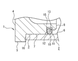
- (1) is an end cap, and the tip side is an insertion part (3) to the rail body (2). Further, a contact flange (5) is provided on the outer periphery of the base end (4) of the end cap (1).
- the outer diameter of the insertion portion (3) is formed to be approximately the same as the inner diameter of the rail body (2), and when the insertion portion (3) is inserted and arranged in the rail body (2), the rail body (2) It arrange
- an engaging groove (10) is provided on the distal end side of the insertion part (3) of the end cap (1).
- the engaging groove (10) is composed of a pair of side surfaces (11), (12) and a bottom surface (13) and has a U-shaped cross section.
- a tapered wall surface (14) having a tapered shape with a small diameter on the distal end surface (8) side is provided between the distal end surface (8) and the outer peripheral surface (7) of the insertion portion (3).
- the engagement groove (10) is formed by providing the engagement groove (10) including the pair of side surfaces (11), (12) and the bottom surface (13) in the insertion portion (3) of the end cap (1).
- the brazing material ring (15) is difficult to be detached from the end cap (1). Therefore, when the insertion part (3) of the end cap (1) is inserted and arranged in the rail body (2), the brazing ring (15) is not displaced and is not detached from the end cap (1). It is possible to place the brazing material ring (15) in the rail body (2) while maintaining the correct position, and the end cap (1) and the rail body (2) can be brazed easily and reliably. be able to.
- the stress concentration as in the case where the step portion for placing the brazing material ring (15) on the rail body (2) is formed by cutting. There is no possibility of causing damage when internal pressure is applied. Further, since the cross-sectional shape of the engaging groove (10) is U-shaped, the brazing material ring (15) can be held in the engaging groove (10) in a state in which it is difficult to disengage.
- a brazing material ring (15) is disposed in the engaging groove (10) of the end cap (1) formed as described above.
- the tapered wall surface (14) having a small diameter on the distal end surface (8) side is provided at the distal end of the insertion portion (3) as described above, the brazing material is made along the tapered wall surface (14). Since the ring (15) can be smoothly inserted into the engaging groove (10) from the tip of the inserting part (3) through the outer periphery of the inserting part (3), the brazing into the engaging groove (10) The work of inserting the material ring (15) can be facilitated.
- the insertion portion (3) of the end cap (1) formed as described above is inserted and arranged in the rail body (2) so as to be provided on the outer periphery of the base end (4) of the end cap (1) as shown in FIG.
- the contact flange (5) comes into contact with the end surface (16) of the rail body (2).
- the engaging groove (10) is provided only at one location of the end cap (1).
- the engaging groove (10) is provided only at one location of the end cap (1).
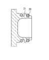
- not only this but also one as shown in FIG. It is also possible to provide two engagement grooves (20) and (21) in the end cap (1).
- the contact flange (5) is provided on the base end (4) side of the end cap (1).
- the present invention is not limited to this in other different embodiments, but as shown in FIG. 4 (a). It is also possible to integrally form the male screw part (22) on the base end (4) side, or to integrally form the female screw part (23) on the base end (4) side as shown in FIG. 4 (b).
Landscapes
- Engineering & Computer Science (AREA)
- Chemical & Material Sciences (AREA)
- Combustion & Propulsion (AREA)
- Mechanical Engineering (AREA)
- General Engineering & Computer Science (AREA)
- Fuel-Injection Apparatus (AREA)
- Pressure Vessels And Lids Thereof (AREA)
Priority Applications (6)
| Application Number | Priority Date | Filing Date | Title |
|---|---|---|---|
| KR1020197005941A KR20190029743A (ko) | 2016-08-05 | 2017-06-26 | 엔드 캡 |
| US16/319,825 US10808663B2 (en) | 2016-08-05 | 2017-06-26 | End cap |
| EP17836641.5A EP3477092B1 (en) | 2016-08-05 | 2017-06-26 | End cap |
| KR1020207036550A KR102296324B1 (ko) | 2016-08-05 | 2017-06-26 | 엔드 캡 |
| MX2019001491A MX2019001491A (es) | 2016-08-05 | 2017-06-26 | Tapa de extremo. |
| CN201780047697.XA CN109642530B (zh) | 2016-08-05 | 2017-06-26 | 端盖 |
Applications Claiming Priority (2)
| Application Number | Priority Date | Filing Date | Title |
|---|---|---|---|
| JP2016-154971 | 2016-08-05 | ||
| JP2016154971A JP6850089B2 (ja) | 2016-08-05 | 2016-08-05 | エンドキャップ |
Publications (1)
| Publication Number | Publication Date |
|---|---|
| WO2018025534A1 true WO2018025534A1 (ja) | 2018-02-08 |
Family
ID=61073646
Family Applications (1)
| Application Number | Title | Priority Date | Filing Date |
|---|---|---|---|
| PCT/JP2017/023402 Ceased WO2018025534A1 (ja) | 2016-08-05 | 2017-06-26 | エンドキャップ |
Country Status (7)
| Country | Link |
|---|---|
| US (1) | US10808663B2 (https=) |
| EP (1) | EP3477092B1 (https=) |
| JP (1) | JP6850089B2 (https=) |
| KR (2) | KR20190029743A (https=) |
| CN (1) | CN109642530B (https=) |
| MX (1) | MX2019001491A (https=) |
| WO (1) | WO2018025534A1 (https=) |
Families Citing this family (6)
| Publication number | Priority date | Publication date | Assignee | Title |
|---|---|---|---|---|
| JP6788431B2 (ja) * | 2016-08-25 | 2020-11-25 | 臼井国際産業株式会社 | エンドキャップ |
| DE102018110342B4 (de) * | 2018-04-30 | 2022-09-01 | Benteler Automobiltechnik Gmbh | Verfahren zur Herstellung eines Kraftstoffverteilers |
| CN111425691B (zh) * | 2020-04-20 | 2021-12-14 | 神华国能集团有限公司 | 管路密封装置及管路系统 |
| US20220307454A1 (en) * | 2021-03-26 | 2022-09-29 | Robert Bosch Gmbh | Fitting for a Fluid Delivery System |
| CN217977611U (zh) * | 2022-06-01 | 2022-12-06 | 浙江盾安禾田金属有限公司 | 截止阀及空调系统 |
| CN114893271B (zh) * | 2022-06-07 | 2024-04-19 | 湖州通源机械零部件有限公司 | 一种插入式挺柱焊接结构的生产工艺 |
Citations (5)
| Publication number | Priority date | Publication date | Assignee | Title |
|---|---|---|---|---|
| JPS5865970A (ja) * | 1981-10-15 | 1983-04-19 | Yamaha Motor Co Ltd | 燃料噴射装置におけるデリバリパイプ |
| JPH09144624A (ja) * | 1995-11-20 | 1997-06-03 | Toyoda Gosei Co Ltd | 燃料圧力脈動減衰装置 |
| US20150007796A1 (en) * | 2012-02-02 | 2015-01-08 | Benteler Automobiltechnik Gmbh | Fuel distributor bar |
| JP2016020678A (ja) * | 2014-07-16 | 2016-02-04 | 臼井国際産業株式会社 | ガソリン直噴エンジン用燃料レールの端末シール構造 |
| JP2016037928A (ja) | 2014-08-08 | 2016-03-22 | 臼井国際産業株式会社 | ガソリン直噴エンジン用燃料レールの端末シール構造 |
Family Cites Families (12)
| Publication number | Priority date | Publication date | Assignee | Title |
|---|---|---|---|---|
| US3675685A (en) * | 1970-09-08 | 1972-07-11 | Amvit | Pipe stopper for bell and spigot type of tile |
| JPS5652994Y2 (https=) * | 1973-04-23 | 1981-12-10 | ||
| US4269230A (en) * | 1979-02-26 | 1981-05-26 | Genova, Inc. | Closure member |
| US4342419A (en) * | 1980-10-31 | 1982-08-03 | Beckman Instruments, Inc. | Safety cover for centrifuge bucket |
| US4344460A (en) * | 1980-11-28 | 1982-08-17 | Advance Valve Installations | Apparatus for plugging a pressure piping system |
| US4750525A (en) * | 1985-04-15 | 1988-06-14 | Vaughan Daniel J | End closure for flexible plastic tubes |
| US5605241A (en) * | 1995-01-13 | 1997-02-25 | Imperioli; Rosemarie V. | Hydraulically controlled container discharge lid to prevent spillage |
| US5806566A (en) * | 1997-07-18 | 1998-09-15 | Taylor; James R. | Storm drainage conduit plug and sealing band therefor |
| US20070040375A1 (en) * | 2005-08-17 | 2007-02-22 | Fierst Raymond V | Locating appliance for a non-metallic piping member |
| JP2011144768A (ja) * | 2010-01-15 | 2011-07-28 | Maruyasu Industries Co Ltd | 直噴エンジン用高圧燃料デリバリパイプ及びその製造方法 |
| US8413689B1 (en) * | 2011-12-16 | 2013-04-09 | James R. Taylor | Storm drainage conduit plug with a sealing band |
| KR20160069534A (ko) * | 2014-12-08 | 2016-06-17 | 주식회사 현대케피코 | 고강도 조립 구조를 갖는 연료레일 |
-
2016
- 2016-08-05 JP JP2016154971A patent/JP6850089B2/ja active Active
-
2017
- 2017-06-26 KR KR1020197005941A patent/KR20190029743A/ko not_active Ceased
- 2017-06-26 CN CN201780047697.XA patent/CN109642530B/zh active Active
- 2017-06-26 MX MX2019001491A patent/MX2019001491A/es unknown
- 2017-06-26 WO PCT/JP2017/023402 patent/WO2018025534A1/ja not_active Ceased
- 2017-06-26 KR KR1020207036550A patent/KR102296324B1/ko active Active
- 2017-06-26 EP EP17836641.5A patent/EP3477092B1/en active Active
- 2017-06-26 US US16/319,825 patent/US10808663B2/en active Active
Patent Citations (5)
| Publication number | Priority date | Publication date | Assignee | Title |
|---|---|---|---|---|
| JPS5865970A (ja) * | 1981-10-15 | 1983-04-19 | Yamaha Motor Co Ltd | 燃料噴射装置におけるデリバリパイプ |
| JPH09144624A (ja) * | 1995-11-20 | 1997-06-03 | Toyoda Gosei Co Ltd | 燃料圧力脈動減衰装置 |
| US20150007796A1 (en) * | 2012-02-02 | 2015-01-08 | Benteler Automobiltechnik Gmbh | Fuel distributor bar |
| JP2016020678A (ja) * | 2014-07-16 | 2016-02-04 | 臼井国際産業株式会社 | ガソリン直噴エンジン用燃料レールの端末シール構造 |
| JP2016037928A (ja) | 2014-08-08 | 2016-03-22 | 臼井国際産業株式会社 | ガソリン直噴エンジン用燃料レールの端末シール構造 |
Non-Patent Citations (1)
| Title |
|---|
| See also references of EP3477092A4 |
Also Published As
| Publication number | Publication date |
|---|---|
| US20190264643A1 (en) | 2019-08-29 |
| JP2018021539A (ja) | 2018-02-08 |
| US10808663B2 (en) | 2020-10-20 |
| EP3477092A4 (en) | 2020-02-26 |
| JP6850089B2 (ja) | 2021-03-31 |
| CN109642530B (zh) | 2021-04-27 |
| CN109642530A (zh) | 2019-04-16 |
| EP3477092C0 (en) | 2024-07-31 |
| EP3477092A1 (en) | 2019-05-01 |
| MX2019001491A (es) | 2019-05-15 |
| KR20190029743A (ko) | 2019-03-20 |
| KR102296324B1 (ko) | 2021-09-01 |
| KR20200145841A (ko) | 2020-12-30 |
| EP3477092B1 (en) | 2024-07-31 |
Similar Documents
| Publication | Publication Date | Title |
|---|---|---|
| WO2018025534A1 (ja) | エンドキャップ | |
| US8696210B2 (en) | Two-piece retainer and two-piece roller bearing | |
| JP5485843B2 (ja) | グロープラグ及びその製造方法 | |
| JP2018051690A (ja) | リングケース | |
| US20170021482A1 (en) | Seal removal tool | |
| EP2570710B1 (fr) | Embout surmoulé de raccordement d'une canalisation à un élément d'un circuit de transport de fluide | |
| EP2669578B1 (en) | Glow plug | |
| EP2799705A1 (en) | Fuel Injector Assembly and Sleeve Insert | |
| JP5151612B2 (ja) | 光学用キャップ部品 | |
| JP2012136961A (ja) | デリバリパイプ及びその製造方法 | |
| JP7465628B2 (ja) | ガソリン直噴レール | |
| EP3483422B1 (en) | End cap | |
| WO2020121871A1 (ja) | 管継手及び管継手用芯材 | |
| JP2014057984A (ja) | シリンダブロックの製造方法 | |
| JP2015121246A (ja) | 管継手 | |
| KR20130136579A (ko) | 글로 플러그 | |
| US20170173660A1 (en) | Metal component sturcture and metal component swaging method | |
| JP6639016B2 (ja) | フィラーパイプの入口部の構造 | |
| JP2015221624A (ja) | フィラーカバー | |
| JP6528580B2 (ja) | エンドキャップ及びそれを備えた直動案内装置 | |
| JP6383576B2 (ja) | 黒鉛構造体 | |
| KR20130127939A (ko) | 연료 분사 노즐 | |
| WO2019008887A1 (ja) | インジェクターホルダ | |
| JPH0550163A (ja) | 嵌合部材の軸部材への固定方法および塑性加工工具 | |
| JPH1095358A (ja) | 合成樹脂製リザーバタンクのパイプ部構造 |
Legal Events
| Date | Code | Title | Description |
|---|---|---|---|
| 121 | Ep: the epo has been informed by wipo that ep was designated in this application |
Ref document number: 17836641 Country of ref document: EP Kind code of ref document: A1 |
|
| NENP | Non-entry into the national phase |
Ref country code: DE |
|
| ENP | Entry into the national phase |
Ref document number: 2017836641 Country of ref document: EP Effective date: 20190123 |
|
| ENP | Entry into the national phase |
Ref document number: 20197005941 Country of ref document: KR Kind code of ref document: A |