WO2018020615A1 - 電力変換装置 - Google Patents
電力変換装置 Download PDFInfo
- Publication number
- WO2018020615A1 WO2018020615A1 PCT/JP2016/072039 JP2016072039W WO2018020615A1 WO 2018020615 A1 WO2018020615 A1 WO 2018020615A1 JP 2016072039 W JP2016072039 W JP 2016072039W WO 2018020615 A1 WO2018020615 A1 WO 2018020615A1
- Authority
- WO
- WIPO (PCT)
- Prior art keywords
- unit
- power conversion
- space
- housing
- conversion device
- Prior art date
Links
Images


Classifications
-
- H—ELECTRICITY
- H05—ELECTRIC TECHNIQUES NOT OTHERWISE PROVIDED FOR
- H05K—PRINTED CIRCUITS; CASINGS OR CONSTRUCTIONAL DETAILS OF ELECTRIC APPARATUS; MANUFACTURE OF ASSEMBLAGES OF ELECTRICAL COMPONENTS
- H05K7/00—Constructional details common to different types of electric apparatus
- H05K7/20—Modifications to facilitate cooling, ventilating, or heating
- H05K7/2089—Modifications to facilitate cooling, ventilating, or heating for power electronics, e.g. for inverters for controlling motor
- H05K7/20909—Forced ventilation, e.g. on heat dissipaters coupled to components
- H05K7/20918—Forced ventilation, e.g. on heat dissipaters coupled to components the components being isolated from air flow, e.g. hollow heat sinks, wind tunnels or funnels
-
- H—ELECTRICITY
- H02—GENERATION; CONVERSION OR DISTRIBUTION OF ELECTRIC POWER
- H02M—APPARATUS FOR CONVERSION BETWEEN AC AND AC, BETWEEN AC AND DC, OR BETWEEN DC AND DC, AND FOR USE WITH MAINS OR SIMILAR POWER SUPPLY SYSTEMS; CONVERSION OF DC OR AC INPUT POWER INTO SURGE OUTPUT POWER; CONTROL OR REGULATION THEREOF
- H02M3/00—Conversion of dc power input into dc power output
- H02M3/02—Conversion of dc power input into dc power output without intermediate conversion into ac
- H02M3/04—Conversion of dc power input into dc power output without intermediate conversion into ac by static converters
- H02M3/10—Conversion of dc power input into dc power output without intermediate conversion into ac by static converters using discharge tubes with control electrode or semiconductor devices with control electrode
- H02M3/145—Conversion of dc power input into dc power output without intermediate conversion into ac by static converters using discharge tubes with control electrode or semiconductor devices with control electrode using devices of a triode or transistor type requiring continuous application of a control signal
- H02M3/155—Conversion of dc power input into dc power output without intermediate conversion into ac by static converters using discharge tubes with control electrode or semiconductor devices with control electrode using devices of a triode or transistor type requiring continuous application of a control signal using semiconductor devices only
-
- H—ELECTRICITY
- H02—GENERATION; CONVERSION OR DISTRIBUTION OF ELECTRIC POWER
- H02M—APPARATUS FOR CONVERSION BETWEEN AC AND AC, BETWEEN AC AND DC, OR BETWEEN DC AND DC, AND FOR USE WITH MAINS OR SIMILAR POWER SUPPLY SYSTEMS; CONVERSION OF DC OR AC INPUT POWER INTO SURGE OUTPUT POWER; CONTROL OR REGULATION THEREOF
- H02M7/00—Conversion of ac power input into dc power output; Conversion of dc power input into ac power output
- H02M7/003—Constructional details, e.g. physical layout, assembly, wiring or busbar connections
-
- H—ELECTRICITY
- H02—GENERATION; CONVERSION OR DISTRIBUTION OF ELECTRIC POWER
- H02M—APPARATUS FOR CONVERSION BETWEEN AC AND AC, BETWEEN AC AND DC, OR BETWEEN DC AND DC, AND FOR USE WITH MAINS OR SIMILAR POWER SUPPLY SYSTEMS; CONVERSION OF DC OR AC INPUT POWER INTO SURGE OUTPUT POWER; CONTROL OR REGULATION THEREOF
- H02M7/00—Conversion of ac power input into dc power output; Conversion of dc power input into ac power output
- H02M7/42—Conversion of dc power input into ac power output without possibility of reversal
- H02M7/44—Conversion of dc power input into ac power output without possibility of reversal by static converters
- H02M7/48—Conversion of dc power input into ac power output without possibility of reversal by static converters using discharge tubes with control electrode or semiconductor devices with control electrode
-
- H—ELECTRICITY
- H05—ELECTRIC TECHNIQUES NOT OTHERWISE PROVIDED FOR
- H05K—PRINTED CIRCUITS; CASINGS OR CONSTRUCTIONAL DETAILS OF ELECTRIC APPARATUS; MANUFACTURE OF ASSEMBLAGES OF ELECTRICAL COMPONENTS
- H05K7/00—Constructional details common to different types of electric apparatus
- H05K7/20—Modifications to facilitate cooling, ventilating, or heating
- H05K7/2039—Modifications to facilitate cooling, ventilating, or heating characterised by the heat transfer by conduction from the heat generating element to a dissipating body
- H05K7/20409—Outer radiating structures on heat dissipating housings, e.g. fins integrated with the housing
-
- H—ELECTRICITY
- H05—ELECTRIC TECHNIQUES NOT OTHERWISE PROVIDED FOR
- H05K—PRINTED CIRCUITS; CASINGS OR CONSTRUCTIONAL DETAILS OF ELECTRIC APPARATUS; MANUFACTURE OF ASSEMBLAGES OF ELECTRICAL COMPONENTS
- H05K7/00—Constructional details common to different types of electric apparatus
- H05K7/20—Modifications to facilitate cooling, ventilating, or heating
- H05K7/2089—Modifications to facilitate cooling, ventilating, or heating for power electronics, e.g. for inverters for controlling motor
- H05K7/20909—Forced ventilation, e.g. on heat dissipaters coupled to components
-
- B—PERFORMING OPERATIONS; TRANSPORTING
- B60—VEHICLES IN GENERAL
- B60L—PROPULSION OF ELECTRICALLY-PROPELLED VEHICLES; SUPPLYING ELECTRIC POWER FOR AUXILIARY EQUIPMENT OF ELECTRICALLY-PROPELLED VEHICLES; ELECTRODYNAMIC BRAKE SYSTEMS FOR VEHICLES IN GENERAL; MAGNETIC SUSPENSION OR LEVITATION FOR VEHICLES; MONITORING OPERATING VARIABLES OF ELECTRICALLY-PROPELLED VEHICLES; ELECTRIC SAFETY DEVICES FOR ELECTRICALLY-PROPELLED VEHICLES
- B60L2200/00—Type of vehicles
- B60L2200/26—Rail vehicles
-
- B—PERFORMING OPERATIONS; TRANSPORTING
- B60—VEHICLES IN GENERAL
- B60L—PROPULSION OF ELECTRICALLY-PROPELLED VEHICLES; SUPPLYING ELECTRIC POWER FOR AUXILIARY EQUIPMENT OF ELECTRICALLY-PROPELLED VEHICLES; ELECTRODYNAMIC BRAKE SYSTEMS FOR VEHICLES IN GENERAL; MAGNETIC SUSPENSION OR LEVITATION FOR VEHICLES; MONITORING OPERATING VARIABLES OF ELECTRICALLY-PROPELLED VEHICLES; ELECTRIC SAFETY DEVICES FOR ELECTRICALLY-PROPELLED VEHICLES
- B60L2210/00—Converter types
- B60L2210/40—DC to AC converters
- B60L2210/42—Voltage source inverters
Definitions
- This invention relates to a power converter.
- An electric power conversion device that converts electric power acquired from an overhead line and supplies it to an electric motor or in-vehicle equipment is mounted on the roof or under the floor of an electric railway vehicle.
- the power conversion device includes a power conversion unit that converts input power by a switching operation of a semiconductor element and outputs desired AC power. Since the semiconductor element generates heat when performing a switching operation, a fin or a sword-shaped heat sink that dissipates heat transmitted from the semiconductor element is formed. In order to increase the cooling efficiency, the heat sink is provided at a position where it comes into contact with outside air.
- the semiconductor elements that make up the power conversion unit and the electronic components that make up the output control unit that outputs control signals to the power conversion unit are installed inside a housing that does not come into contact with the outside air in order to prevent failure due to dust and moisture. It is done.
- the installation location of each part which comprises a power converter device is determined according to the necessity for cooling, and the necessity for dust prevention and waterproofing.
- the storage box of the forced air-cooled vehicle equipment storage device described as the prior art has a semiconductor room, a blower room, and a wind tunnel into which outside air does not flow.
- An air inlet is formed in the side wall of the blower chamber, and a cross-flow fan provided in the blower chamber sucks outside air and discharges air toward the wind tunnel.
- a cooling fin on which a semiconductor element is mounted is provided in the wind tunnel, and the cooling fin is cooled by the air from the cross-flow fan, thereby suppressing the temperature rise of the semiconductor element.
- a semiconductor room In the forced air-cooled vehicle equipment storage device, a semiconductor room, a blower room, and a wind tunnel are provided, and the fan is housed in a casing. There is a problem of complexity.
- the present invention has been made in view of the above circumstances, and an object thereof is to simplify the structure of a power conversion device while maintaining cooling performance.
- a power conversion device of the present invention includes a power conversion unit that converts and outputs input power, a reactor connected to the input side of the power conversion unit, and an electronic component included in the power conversion unit.
- a power conversion device including a control unit to be controlled, including a first unit, a second unit, and a third unit.
- the first unit is divided into a sealed portion where the outside air does not flow and an open portion where the outside air flows, by the partition wall inside the first unit.
- the first unit has a heat sink exposed in the open portion that houses the electronic component in the sealed portion and dissipates heat transferred from the electronic component.
- the second unit is adjacent to the first unit, and the interior of the housing is divided into a first space and a second space by a partition having an opening.
- the second unit blows air from the second space toward the first space, and houses a blower having an impeller in which at least a part is exposed to the second space from the opening in the first space.
- the third unit is adjacent to the second unit and houses the reactor.
- a first ventilation port is formed at a portion where the housing of the first unit that forms the opening and the housing of the second unit that forms the second space are in contact with each other.
- An inflow port through which outside air flows into the housing of the first unit forming the open portion is formed.
- a second ventilation port is formed at a portion where the housing of the second unit and the housing of the third unit that form the first space are in contact with each other.
- An outlet for discharging the air flowing in from the second ventilation port is formed in the housing of the third unit.
- the first unit having the sealed portion and the open portion in which the electronic components included in the power conversion unit are accommodated, the second unit in which the blower is accommodated, and the third in which the reactor is accommodated.
- casing of the power converter device which concerns on embodiment of this invention The perspective view of the housing
- casing of the 3rd unit which concerns on embodiment The figure which shows the example of mounting to the electric railway vehicle of the power converter device which concerns on embodiment
- the perspective view of the electronic component contained in the power conversion part which concerns on embodiment The perspective view of the air blower concerning an embodiment Sectional drawing of the power converter concerning an embodiment Sectional drawing of the power converter concerning an embodiment Sectional drawing of the power converter concerning an embodiment
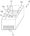
- FIG. 1 is a perspective view of a casing of a power converter according to an embodiment of the present invention.
- the power conversion device 1 is configured by combining units to be described later. By securing a flow path of air passing between the units, each part of the power conversion device 1 can be cooled.
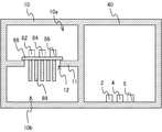
- the power conversion device 1 includes a first unit 10, a second unit 20, a third unit 30, and a fourth unit 40 of the same size.
- the fourth unit 40 is adjacent to the second unit 20 and the third unit 30, respectively. That is, in the example of FIG.
- the adjacent direction of the first unit 10 and the second unit 20 is orthogonal to the adjacent direction of the second unit 20 and the third unit 30, and the fourth unit 40 is Adjacent to one unit 10 and third unit 30.
- an opening that enables attachment and removal of electronic components that constitute the power conversion device 1 and a lid that closes the opening are provided.
- the first unit 10 is divided into a sealed portion 10a where the outside air does not flow and an open portion 10b where the outside air flows, by the partition wall 11 inside the housing.
- An electronic component included in the power conversion unit, which will be described later, is accommodated in the sealing portion 10a, and the first unit 10 has a heat sink exposed to the open portion 10b that dissipates heat transmitted from the electronic component. Since the opening 12 formed in the partition wall 11 is closed by a substrate provided with the electronic component, which will be described later, outside air does not flow into the sealed portion 10a that is a space in which the electronic component is accommodated. In the example of FIG. 1, two openings 12 are formed in the partition wall 11, but the number of openings 12 is arbitrary.
- the first ventilation port 14 is formed at a portion where the housing of the first unit 10 that forms the opening 10b and the housing of the second unit 20 that forms the second space described later are in contact.
- An inflow port 13 through which outside air flows into the housing of the first unit 10 that forms the opening 10b is formed.
- the inside of the housing is divided into a first space 20 a and a second space 20 b by a partition wall 21, and an opening 22 is formed in the partition wall 21.
- the first ventilation port 14 is formed at a portion where the housing of the first unit 10 that forms the open portion 10b and the housing of the second unit 20 that forms the second space 20b are in contact with each other. Is done.
- a second ventilation port 23 is formed at a portion where the housing of the second unit 20 and the housing of the third unit 30 that form the first space 20a are in contact with each other.
- the second unit 20 accommodates a blower that blows air from the second space 20b to the first space 20a, which will be described later.
- the second ventilation port 23 and the outlet 31 for discharging the air flowing in from the second ventilation port 23 are formed.
- the third unit 30 accommodates a reactor described later. Due to the operation of the blower housed in the second unit 20, the outside air that has flowed into the opening 10 b from the inlet 13 flows into the second space 20 b through the first ventilation port 14. The air that has flowed into the second space 20 b flows into the first space 20 a through the opening 22, flows into the third unit 30 through the second ventilation port 23, and the power conversion device 1 from the outlet 31. Is discharged outside.
- the outside air does not flow into the fourth unit 40.
- the fourth unit 40 accommodates electronic components that are required to be waterproof and dustproof.
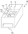
- FIGS. 2 and 3 are perspective views of the casing of the first unit according to the embodiment.
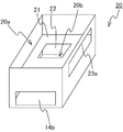
- FIG. 4 is a perspective view of the housing of the second unit according to the embodiment.
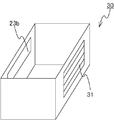
- FIG. 5 is a perspective view of the housing of the third unit according to the embodiment.
- the opening portion 10 b is formed, and the outflow port 14 a is formed in a part of the casing of the first unit 10 that is in contact with the second unit 20.
- An inlet 13 facing the outlet 14 a is formed in the housing of the first unit 10.
- An inflow port 14 b that forms the second space 20 b and faces the outflow port 14 a is formed in a part of the housing of the second unit 20 that is in contact with the first unit 10.
- the outflow port 14 a of the first unit 10 and the inflow port 14 b of the second unit 20 constitute a first ventilation port 14.
- An outlet 23 a is formed in a part of the housing of the second unit 20 that forms the first space 20 a and is in contact with the third unit 30.
- An inflow port 23 b that faces the outflow port 23 a is formed in a part of the housing of the third unit 30 that is in contact with the second unit 20.
- a second ventilation port 23 is formed by the outlet 23 a of the second unit 20 and the inlet 23 b of the third unit 30.
- An outlet 31 that faces the inlet 23 b is formed in the housing of the third unit 30.
- the inlet 13 and the first vent 14 are opposed to each other, and the second vent 23 and the outlet 31 are opposed to each other.
- the inlet 13, the first vent 14, and the second vent are opposed to each other.
- the position where the ventilation port 23 and the outflow port 31 are provided is not limited to the above example.
- the inlet 13, the first vent 14, and the second air can be placed at arbitrary positions so that outside air flows in from the first unit 10, passes through the second unit 20, and is discharged from the third unit 30. Ventilation port 23 and outflow port 31 can be provided.
- FIG. 6 is a diagram illustrating an example in which the power conversion device according to the embodiment is mounted on an electric railway vehicle.
- the power conversion device 1 converts the power acquired from the overhead line 101 via the current collector 102 and is connected to the output side.
- the electric motor 103 that drives the electric railway vehicle and the load device that is an air conditioner or a lighting device Power is supplied to 104.
- the power acquired from the overhead line 101 is input to the power conversion units 70 and 80 via the switch 2 and the input reactor 3.
- the power conversion unit 70 is an inverter circuit having a capacitor 71 and switching elements 72, 73, 74, 75, 76, 77.
- the power conversion unit 80 is an inverter circuit having a capacitor 81 and switching elements 82, 83, 84, 85, 86 and 87.
- Each switching element in FIG. 6 is an IGBT (Insulated Gate Bipolar Transistor), but any semiconductor element can be used.
- the configurations of the power conversion unit 70 and the power conversion unit 80 are not limited to the example of FIG.
- the power converter 80 may be a DC-DC converter (Direct-Current-to-Direct-Current Converter).
- the reactor 3 is manufactured by winding a copper or aluminum conductor in a coil shape. During the operation of the reactor 3, a large loss occurs due to the resistance of the conductor, so that it is necessary to forcibly cool it.
- the control unit 4 controls on / off switching of the switch 2 and switching of the switching elements 72, 73, 74, 75, 76, 77, 82, 83, 84, 85, 86, 87.
- the smoothing circuit 5 smoothes the pulse waveform output from the power conversion unit 80.
- the smoothing circuit 5 provides a sine wave alternating current.
- the blower 6 is driven by the output of the power converter 80 smoothed by the smoothing circuit 5.
- the output of the power converter 80 smoothed by the smoothing circuit 5 is supplied to the load device 104.
- the switch 2, the control unit 4, and the smoothing circuit 5 generate less heat than the electronic components included in the reactor 3 and the power conversion units 70 and 80. About switch 2, control part 4, and smoothing circuit 5, it is necessary to prevent failure by
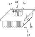
- FIG. 7 is a perspective view of an electronic component included in the power conversion unit according to the embodiment.
- Electronic components included in the power conversion units 70 and 80 are provided on the substrate 88, and a heat sink is formed on the surface of the substrate 88 opposite to the surface on which the electronic components are provided.
- the switching elements 82, 83, and 84 included in the power conversion unit 80 are shown.
- the switching elements 82, 83, and 84 are provided on the substrate 88.
- fins 89 are provided as heat sinks on the surface opposite to the surface on which the switching elements 82, 83, and 84 are provided. It is formed.
- FIG. 8 is a perspective view of the blower according to the embodiment.
- the blower 6 includes a base 61 in which an opening is formed, a support portion 62 fixed to the base 61, a blower motor 63 supported by the support portion 62, and an impeller 64 rotated by the blower motor 63.
- the impeller 64 is not stored in the casing and is exposed.
- the blower 6 is a centrifugal blower, but any blower can be used.
- each part of the power conversion device 1 in the housing of the power conversion device 1 shown in FIG. 1 will be described.
- the electronic components included in the power conversion units 70 and 80 that need to be forcibly cooled are accommodated in the first unit 10, and the blower 6 is accommodated in the second unit 20, and the reactor that needs to be forcibly cooled. 3 is accommodated in the third unit 30, and the switch 2, the control unit 4, and the smoothing circuit 5 are accommodated in the fourth unit 40.
- the connection conductor that connects each part of the power conversion device 1 accommodated in a different unit may be led out of the unit, or a hole through which the connection conductor is inserted may be provided in a partition between the units.
- FIG. 9, FIG. 10, and FIG. 11 are cross-sectional views of the power converter according to the embodiment.
- 9 is a cross-sectional view taken along line AA in FIG. 1
- FIG. 10 is a cross-sectional view taken along line BB in FIG. 1
- FIG. 11 is a cross-sectional view taken along line CC in FIG. FIG.
- the substrate 88 shown in FIG. 7 is provided in the sealed portion 10a, the opening 12 is closed by the substrate 88, and the fin 89 is exposed from the opening 12 to the open portion 10b. Since the opening 12 is blocked by the substrate 88, the outside air does not flow into the sealed portion 10a. On the other hand, outside air flows into the opening 10b from the inflow port 13.
- the blower 6 blows air from the second space 20b toward the first space 20a, and at least a part of the impeller 64 is exposed to the second space 20b from the opening 22.
- the rotation center axis of the impeller 64 is orthogonal to the partition wall 21.
- the direction in which the reactor 3 is accommodated is arbitrary, but when the second ventilation port 23 and the outlet 31 face each other, the central axis of the reactor 3 coincides with the direction from the second ventilation port 23 toward the outlet 31.
- the reactor 3 is attached to a frame (not shown) with a bolt, and the frame is fixed inside the housing of the third unit 30.
- the air flow is indicated by white arrows.
- the outside air that has flowed into the open portion 10b from the inflow port 13 passes between the fins 89, and flows into the second space 20b through the first ventilation port 14.
- the center of the impeller 64 becomes negative pressure, so the air in the second space 20b is sucked into the impeller 64 through the opening 22, and the first It is discharged into the space 20a.
- the air discharged into the first space 20 a flows into the third unit 30 through the second ventilation port 23.
- the air flowing into the third unit 30 passes through the reactor 3 and is discharged from the outlet 31 to the outside of the power conversion device 1.
- the power conversion device 1 Since the power conversion device 1 has an air flow path from the inflow port 13 to the outflow port 31 through the first ventilation port 14, the opening 22, and the second ventilation port 23, the power conversion unit 70, It is possible to cool the electronic components and the reactor 3 included in 80. Since the power conversion device 1 does not have the exhaust duct and the casing of the blower 6, the structure is simple.
- the structure of the power conversion device 1 can be simplified.
- the electronic components included in the power conversion device 1 can be provided at appropriate positions according to the necessity for cooling and the necessity for dustproofing and waterproofing.
- the electronic components can be attached to each unit from the upper surface of the power conversion device 1, so that assembly is easy.
- the first unit 10 having the sealed portion 10a and the open portion 10b in which the electronic components are accommodated, and the second unit 20 in which the blower 6 is accommodated.
- the third unit 30 in which the reactor 3 is accommodated, and the flow of air from the inlet 13 to the outlet 31 through the first ventilation port 14, the opening 22, and the second ventilation port 23.
- the power conversion device 1 includes one unit, but the power conversion device 1 includes at least one first unit 10, at least one second unit 20, and at least one unit. What is necessary is just to provide the 3rd unit 30, and how to combine a unit is arbitrary.
- the size of each unit is the same, but the size of each unit may be different depending on the electronic component to be accommodated.
- the power conversion device 1 may include a plurality of first units 10 or may increase the size of the first unit 10 compared to other units.
- the power conversion device 1 is installed on the roof of the electric railway vehicle, but can be installed under the floor of the electric railway vehicle with the vertical direction reversed.
Landscapes
- Engineering & Computer Science (AREA)
- Microelectronics & Electronic Packaging (AREA)
- Power Engineering (AREA)
- Physics & Mathematics (AREA)
- Thermal Sciences (AREA)
- Inverter Devices (AREA)
- Cooling Or The Like Of Electrical Apparatus (AREA)
- Dc-Dc Converters (AREA)
Abstract
第1のユニット(10)の密閉部(10a)には、電力変換部に含まれる電子部品が収容され、第1のユニット(10)は、該電子部品から伝達された熱を放熱する開放部(10b)に露出したヒートシンクを有する。第2のユニット(20)の第1の空間(20a)には送風機が収容され、送風機の羽根車の少なくとも一部は開口(22)から第2の空間(20b)に露出する。第3のユニット(30)には、リアクトルが収容される。外気は、流入口(13)から流入し、電力変換装置(1)の内部に流入し、開放部(10b)、第1の通風口(14)、第2の空間(20b)、開口(22)、第1の空間(20a)、第2の通風口(23)、および第3のユニット(30)を通って、流出口(31)から電力変換装置(1)の外部に排出される。
Description
この発明は、電力変換装置に関する。
電気鉄道車両の屋根上または床下には、架線から取得した電力を変換して電動機または車載機器に供給する電力変換装置が搭載される。電力変換装置は、半導体素子のスイッチング動作によって入力電力を変換して所望の交流電力を出力する電力変換部を有する。半導体素子はスイッチング動作を行う際に発熱するため、半導体素子から伝達された熱を放熱するフィンまたは剣山状のヒートシンクが形成される。冷却効率を高めるため、ヒートシンクは、外気に触れる位置に設けられる。一方、電力変換部を構成する半導体素子および電力変換部に制御信号を出力する出力制御部を構成する電子部品は、粉塵および水分による故障を防止するため、外気に触れない筐体の内部に設けられる。このように、電力変換装置を構成する各部品の設置場所は、冷却の必要性ならびに防塵および防水の必要性に応じて決定される。
特許文献1において、従来技術として記載されている強制空冷型車両用機器収納装置の収納箱は、外気が流入しない半導体室、送風機室、および風洞を有する。送風機室の側壁に空気入口が形成され、送風機室に設けられた横流ファンが外気を吸い込み、風洞に向かって空気を排出する。風洞には、半導体素子が装着された冷却フィンが設けられており、横流ファンからの空気で冷却フィンが冷却されることで、半導体素子の温度上昇が抑制される。
上記強制空冷型車両用機器収納装置では、半導体室、送風機室、および風洞がそれぞれ設けられ、またファンはケーシングに収納されているため、装置の大型化、構成部材数の増加、および組み立て作業の複雑化という課題がある。
本発明は上述の事情に鑑みてなされたものであり、冷却性能を維持しながら、電力変換装置の構造を簡易化することが目的である。
上記目的を達成するために、本発明の電力変換装置は、入力電力を変換して出力する電力変換部、電力変換部の入力側に接続されるリアクトル、および電力変換部に含まれる電子部品を制御する制御部を備える電力変換装置であって、第1のユニット、第2のユニット、および第3のユニットを備える。第1のユニットは、筐体の内部が隔壁によって、外気が流入しない密閉部と外気が流入する開放部に分けられる。第1のユニットは、密閉部に電子部品を収容し、電子部品から伝達された熱を放熱する、開放部に露出したヒートシンクを有する。第2のユニットは第1のユニットに隣接し、筐体の内部が開口を有する隔壁によって第1の空間と第2の空間に分けられる。第2のユニットは、第2の空間から第1の空間に向かって送風し、少なくとも一部が開口から第2の空間に露出する羽根車を有する送風機を第1の空間に収容する。第3のユニットは、第2のユニットに隣接し、リアクトルを収容する。開放部を形成する第1のユニットの筐体と、第2の空間を形成する第2のユニットの筐体とが接する部分に第1の通風口が形成される。開放部を形成する第1のユニットの筐体に外気が流入する流入口が形成される。第1の空間を形成する第2のユニットの筐体と第3のユニットの筐体とが接する部分に第2の通風口が形成される。第3のユニットの筐体に第2の通風口から流入した空気を排出する流出口が形成される。
本発明によれば、電力変換部に含まれる電子部品が収容される密閉部と開放部とを有する第1のユニット、送風機が収容される第2のユニット、およびリアクトルが収容される第3のユニットを設け、第1のユニットの流入口から、第2のユニットを通って、第3のユニットの流出口に至る空気の流路を設けることで、冷却性能を維持しながら、電力変換装置の構造を簡易化することが可能である。
以下、本発明の実施の形態について図面を参照して詳細に説明する。なお図中、同一または同等の部分には同一の符号を付す。
図1は、本発明の実施の形態に係る電力変換装置の筐体の斜視図である。図1においては、電力変換装置1の上面の記載を省略した。電力変換装置1は、後述する各ユニットを組み合わせて構成される。ユニット間を通る空気の流路を確保することで、電力変換装置1の各部を冷却することが可能である。図1の例では、電力変換装置1は、同じ大きさの、第1のユニット10、第2のユニット20、第3のユニット30および第4のユニット40で構成され、第1のユニット10および第4のユニット40はそれぞれ、第2のユニット20および第3のユニット30と隣接する。すなわち、図1の例では、第1のユニット10および第2のユニット20の隣接方向と、第2のユニット20および第3のユニット30の隣接方向とは直交し、第4のユニット40は第1のユニット10および第3のユニット30に隣接する。図1において図示されていない電力変換装置1の上面には、電力変換装置1を構成する電子部品の取り付けおよび取り外しを可能にする開口部および開口部を塞ぐ蓋が設けられる。
第1のユニット10は、筐体の内部が隔壁11によって、外気が流入しない密閉部10aと外気が流入する開放部10bに分けられる。密閉部10aには、後述する、電力変換部に含まれる電子部品が収容され、第1のユニット10は、該電子部品から伝達された熱を放熱する開放部10bに露出したヒートシンクを有する。隔壁11に形成される開口12は、後述する、該電子部品が設けられた基板によって塞がれるため、該電子部品が収容される空間である密閉部10aには、外気が流入しない。図1の例では、隔壁11に2つの開口12が形成されているが、開口12の数は任意である。開放部10bを形成する第1のユニット10の筐体と、後述する第2の空間を形成する第2のユニット20の筐体とが接する部分に第1の通風口14が形成される。開放部10bを形成する第1のユニット10の筐体に外気が流入する流入口13が形成される。
第2のユニット20は、筐体の内部が隔壁21によって第1の空間20aと第2の空間20bに分けられ、隔壁21には開口22が形成される。上述のように、開放部10bを形成する第1のユニット10の筐体と、第2の空間20bを形成する第2のユニット20の筐体とが接する部分に第1の通風口14が形成される。第1の空間20aを形成する第2のユニット20の筐体と第3のユニット30の筐体とが接する部分に第2の通風口23が形成される。第2のユニット20には、後述する、第2の空間20bから第1の空間20aに向かって送風する送風機が収容される。
第3のユニット30の筐体に第2の通風口23と第2の通風口23から流入した空気を排出する流出口31が形成される。第3のユニット30には、後述するリアクトルが、収容される。第2のユニット20に収容される送風機の動作によって、流入口13から開放部10bに流入した外気は、第1の通風口14を通って第2の空間20bに流入する。第2の空間20bに流入した空気は開口22を通って第1の空間20aに流入し、第2の通風口23を通って第3のユニット30に流入し、流出口31から電力変換装置1の外部に排出される。
第4のユニット40の内部には、外気が流入しない。第4のユニット40には、防水性および防塵性が求められる電子部品が収容される。
図2および図3は、実施の形態に係る第1のユニットの筐体の斜視図である。図4は、実施の形態に係る第2のユニットの筐体の斜視図である。図5は、実施の形態に係る第3のユニットの筐体の斜視図である。図2から図5の例では、開放部10bを形成し、第2のユニット20に接する第1のユニット10の筐体の一部に流出口14aが形成される。第1のユニット10の筐体に流出口14aと対向する流入口13が形成される。第2の空間20bを形成し、第1のユニット10に接する第2のユニット20の筐体の一部に流出口14aと対向する流入口14bが形成される。第1のユニット10の流出口14aおよび第2のユニット20の流入口14bとで、第1の通風口14が構成される。第1の空間20aを形成し、第3のユニット30に接する第2のユニット20の筐体の一部に流出口23aが形成される。第2のユニット20に接する第3のユニット30の筐体の一部に流出口23aと対向する流入口23bが形成される。第2のユニット20の流出口23aと第3のユニット30の流入口23bとで、第2の通風口23が形成される。第3のユニット30の筐体に流入口23bと対向する流出口31が形成される。上述の例では、流入口13と第1の通風口14とが対向し、第2の通風口23と流出口31とが対向するが、流入口13、第1の通風口14、第2の通風口23および流出口31を設ける位置は、上述の例に限られない。外気が第1のユニット10から流入し、第2のユニット20を通って、第3のユニット30から排出されるように、任意の位置に流入口13、第1の通風口14、第2の通風口23および流出口31を設けることができる。
図6は、実施の形態に係る電力変換装置の電気鉄道車両への搭載例を示す図である。電力変換装置1は、集電装置102を介して架線101から取得した電力を変換して、出力側に接続される、電気鉄道車両を駆動する電動機103および、空調装置または照明装置である負荷装置104に電力を供給する。架線101から取得された電力は、スイッチ2および入力リアクトル3を介して電力変換部70,80に入力される。電力変換部70は、コンデンサ71およびスイッチング素子72,73,74,75,76,77を有するインバータ回路である。電力変換部80は、コンデンサ81およびスイッチング素子82,83,84,85,86,87を有するインバータ回路である。図6の各スイッチング素子は、IGBT(Insulated Gate Bipolar Transistor:絶縁ゲートバイポーラトランジスタ)であるが、任意の半導体素子を用いることができる。電力変換部70および電力変換部80の構成は、図6の例に限られない。負荷装置104に直流電力を供給する場合には、電力変換部80はDC-DC変換器(Direct-Current-to-Direct-Current Converter)であってもよい。
リアクトル3は、銅またはアルミの導体をコイル状に巻き回して製造される。リアクトル3の動作中は、導体の抵抗により大きな損失が発生するため、強制的に冷却する必要がある。制御部4は、スイッチ2のオンオフの切り替え、およびスイッチング素子72,73,74,75,76,77,82,83,84,85,86,87の切り替えを制御する。平滑回路5は、電力変換部80が出力するパルス波形を平滑化する。平滑回路5によって、正弦波交流が得られる。送風機6は、平滑回路5によって平滑化された電力変換部80の出力によって駆動される。負荷装置104には、平滑回路5によって平滑化された電力変換部80の出力が供給される。スイッチ2、制御部4、および平滑回路5は、リアクトル3および電力変換部70,80に含まれる電子部品と比べると、発熱量が小さい。スイッチ2,制御部4、および平滑回路5については、粉塵および水分による故障を防止する必要がある。
電力変換部70,80に含まれる電子部品は発熱するため、外気によって強制的に冷却する必要がある。図7は、実施の形態に係る電力変換部に含まれる電子部品の斜視図である。電力変換部70,80に含まれる電子部品は基板88に設けられ、基板88の面の内、該電子部品が設けられる面と反対側の面にヒートシンクが形成される。図7では、電力変換部80に含まれるスイッチング素子82,83,84を示した。図7の例では、スイッチング素子82,83,84が基板88に設けられ、基板88の面の内、スイッチング素子82,83,84が設けられる面と反対側の面にヒートシンクとして、フィン89が形成される。
図8は、実施の形態に係る送風機の斜視図である。送風機6は、開口が形成されているベース61、ベース61に固定された支持部62、支持部62によって支持される送風機用電動機63、および送風機用電動機63によって回転させられる羽根車64で構成される。羽根車64はケーシングに格納されておらず、露出している。図8の例では、送風機6は遠心送風機であるが、任意の送風機を用いることができる。
電力変換装置1の各部の、図1に示す電力変換装置1の筐体内への設置について説明する。強制的に冷却する必要がある電力変換部70,80に含まれる電子部品は第1のユニット10に収容され、送風機6は第2のユニット20に収容され、強制的に冷却する必要があるリアクトル3は第3のユニット30に収容され、スイッチ2、制御部4、および平滑回路5は第4のユニット40に収容される。異なるユニットに収容される電力変換装置1の各部を接続する接続導体はユニットの外部に引き通されてもよいし、ユニット間の隔壁に接続導体を挿通する孔を設けてもよい。
図9、図10、および図11は、実施の形態に係る電力変換装置の断面図である。図9は、図1におけるA-A線での断面図であり、図10は、図1におけるB-B線での断面図であり、図11は、図1におけるC-C線での断面図である。図7に示す基板88は、密閉部10aに設けられ、基板88によって開口12が塞がれ、フィン89は開口12から開放部10bに露出する。開口12は、基板88に塞がれているため、密閉部10aには外気が流入しない。一方、開放部10bには、流入口13から外気が流入する。
図8に示す送風機6は、第1の空間20aに収容される。送風機6は、第2の空間20bから第1の空間20aに向かって送風し、羽根車64の少なくとも一部は、開口22から第2の空間20bに露出する。図8に示す遠心送風機の場合は、羽根車64の回転中心軸は隔壁21に直交する。リアクトル3を収容する方向は任意であるが、第2の通風口23と流出口31とが対向する場合に、リアクトル3の中心軸を第2の通風口23から流出口31へ向かう方向に一致させるように、リアクトル3を第3のユニット30に収容することで、より効率よくリアクトル3を冷却することが可能である。リアクトル3は、図示しないフレームにボルトで取り付けられ、該フレームが第3のユニット30の筐体の内部に固定される。
図9および図11において、空気の流れを白抜きの矢印で示す。流入口13から開放部10bに流入した外気はフィン89の間を通り、第1の通風口14を通って第2の空間20bに流入する。送風機用電動機63の動作によって羽根車64が回転すると、羽根車64の中心が負圧になるため、第2の空間20bの空気は、開口22を通って羽根車64に吸い込まれ、第1の空間20aに排出される。第1の空間20aに排出された空気は、第2の通風口23を通って、第3のユニット30に流入する。第3のユニット30に流入した空気は、リアクトル3を通って、流出口31から電力変換装置1の外部に排出される。電力変換装置1は、流入口13から、第1の通風口14、開口22、および第2の通風口23を通って、流出口31に至る空気の流路を有するため、電力変換部70,80に含まれる電子部品およびリアクトル3を冷却することが可能である。電力変換装置1は、排気用ダクトおよび送風機6のケーシングを有さないため、構造が簡易である。
第1のユニット10、第2のユニット20、第3のユニット30、および第4のユニット40を組み合わせて電力変換装置1を構成することで、電力変換装置1の構造を簡易化することが可能であり、電力変換装置1に含まれる電子部品を、冷却の必要性ならびに防塵および防水の必要性に応じて適切な位置に設けることが可能である。
また図1の例のように、隔壁11,21を水平に配置した場合には、電力変換装置1の上面から各ユニットに電子部品を取り付けることができるため、組み立てが容易である。
以上説明したとおり、実施の形態に係る電力変換装置1によれば、電子部品が収容される密閉部10aと開放部10bを有する第1のユニット10、送風機6が収容される第2のユニット20、およびリアクトル3が収容される第3のユニット30を設け、流入口13から、第1の通風口14、開口22、および第2の通風口23を通って、流出口31に至る空気の流路を設けることで、冷却性能を維持しながら、電力変換装置1の構造を簡易化することが可能である。
本発明は、上述の実施の形態に限られない。図1の例では、電力変換装置1は、各ユニットを1つずつ備えているが、電力変換装置1は少なくとも1つの第1のユニット10、少なくとも1つの第2のユニット20、および少なくとも1つの第3のユニット30を備えていればよく、ユニットの組み合わせ方は任意である。図1の例では各ユニットの大きさは同じであるが、各ユニットの大きさは収容される電子部品に応じて異なる大きさとしてもよい。電力変換部の数が多い場合には、電力変換装置1は、第1のユニット10を複数備えてもよいし、第1のユニット10の大きさを他のユニットに比べて大きくしてもよい。図1の例では、電力変換装置1は、電気鉄道車両の屋根上に設置されるが、鉛直方向の向きを逆にして、電気鉄道車両の床下に設置することも可能である。
本発明は、本発明の広義の精神と範囲を逸脱することなく、様々な実施の形態及び変形が可能とされるものである。また、上述した実施の形態は、この発明を説明するためのものであり、本発明の範囲を限定するものではない。すなわち、本発明の範囲は、実施の形態ではなく、特許請求の範囲によって示される。そして、特許請求の範囲内及びそれと同等の発明の意義の範囲内で施される様々な変形が、この発明の範囲内とみなされる。
1 電力変換装置、2 スイッチ、3 リアクトル、4 制御部、5 平滑回路、6 送風機、10 第1のユニット、10a 密閉部、10b 開放部、11,21 隔壁、12,22 開口、13 流入口、14 第1の通風口、14a,23a 流出口、14b,23b 流入口、20 第2のユニット、20a 第1の空間、20b 第2の空間、23 第2の通風口、30 第3のユニット、31 流出口、40 第4のユニット、61 ベース、62 支持部、63 送風機用電動機、64 羽根車、70,80 電力変換部、71,81 コンデンサ、72,73,74,75,76,77,82,83,84,85,86,87 スイッチング素子、88 基板、89 フィン、101 架線、102 集電装置、103 電動機、104 負荷装置。
Claims (5)
- 入力電力を変換して出力する電力変換部、前記電力変換部の入力側に接続されるリアクトル、および前記電力変換部に含まれる電子部品を制御する制御部を備える電力変換装置であって、
筐体の内部が隔壁によって、外気が流入しない密閉部と外気が流入する開放部に分けられ、前記密閉部に前記電子部品を収容し、前記電子部品から伝達された熱を放熱する前記開放部に露出したヒートシンクを有する第1のユニットと、
前記第1のユニットに隣接し、筐体の内部が開口を有する隔壁によって第1の空間と第2の空間に分けられ、前記第2の空間から前記第1の空間に向かって送風し、少なくとも一部が前記開口から前記第2の空間に露出する羽根車を有する送風機を前記第1の空間に収容する第2のユニットと、
前記第2のユニットに隣接し、前記リアクトルを収容する第3のユニットと、
を備え、
前記開放部を形成する前記第1のユニットの筐体と、前記第2の空間を形成する前記第2のユニットの筐体とが接する部分に第1の通風口が形成され、前記開放部を形成する前記第1のユニットの筐体に外気が流入する流入口が形成され、前記第1の空間を形成する前記第2のユニットの筐体と前記第3のユニットの筐体とが接する部分に第2の通風口が形成され、前記第3のユニットの筐体に前記第2の通風口から流入した空気を排出する流出口が形成される、
電力変換装置。 - 前記制御部を収容し、外気が内部に流入しない第4のユニットをさらに備える請求項1に記載の電力変換装置。
- 前記電力変換部の入力側に接続され、前記第4のユニットに収容されるスイッチと、
前記電力変換部の出力側に接続され、前記第4のユニットに収容される平滑回路と、
をさらに備え、
前記送風機は前記平滑回路によって平滑化された前記電力変換部の出力によって駆動される、
請求項2に記載の電力変換装置。 - 前記第1のユニットの前記隔壁および前記第2のユニットの前記隔壁は水平であり、
前記第1のユニットの鉛直方向の上部が前記密閉部であって、前記第1のユニットの鉛直方向の下部が前記開放部であり、
前記第2のユニットの鉛直方向の上部の空間が前記第1の空間であって、前記第2のユニットの鉛直方向の下部が前記第2の空間であり、
前記電力変換装置は、車両の屋根上に設置される、
請求項1に記載の電力変換装置。 - 前記制御部を収容し、外気が内部に流入しない第4のユニットをさらに備え、
前記第1のユニットおよび前記第2のユニットの隣接方向と、前記第2のユニットおよび前記第3のユニットの隣接方向とは直交し、
前記第4のユニットは前記第1のユニットおよび前記第3のユニットに隣接する、
請求項4に記載の電力変換装置。
Priority Applications (4)
| Application Number | Priority Date | Filing Date | Title |
|---|---|---|---|
| EP16910518.6A EP3493388B1 (en) | 2016-07-27 | 2016-07-27 | Power conversion device |
| JP2018530263A JP6433631B2 (ja) | 2016-07-27 | 2016-07-27 | 電力変換装置 |
| US16/315,256 US10945355B2 (en) | 2016-07-27 | 2016-07-27 | Power conversion device |
| PCT/JP2016/072039 WO2018020615A1 (ja) | 2016-07-27 | 2016-07-27 | 電力変換装置 |
Applications Claiming Priority (1)
| Application Number | Priority Date | Filing Date | Title |
|---|---|---|---|
| PCT/JP2016/072039 WO2018020615A1 (ja) | 2016-07-27 | 2016-07-27 | 電力変換装置 |
Publications (1)
| Publication Number | Publication Date |
|---|---|
| WO2018020615A1 true WO2018020615A1 (ja) | 2018-02-01 |
Family
ID=61017531
Family Applications (1)
| Application Number | Title | Priority Date | Filing Date |
|---|---|---|---|
| PCT/JP2016/072039 WO2018020615A1 (ja) | 2016-07-27 | 2016-07-27 | 電力変換装置 |
Country Status (4)
| Country | Link |
|---|---|
| US (1) | US10945355B2 (ja) |
| EP (1) | EP3493388B1 (ja) |
| JP (1) | JP6433631B2 (ja) |
| WO (1) | WO2018020615A1 (ja) |
Cited By (5)
| Publication number | Priority date | Publication date | Assignee | Title |
|---|---|---|---|---|
| WO2020126547A1 (en) * | 2018-12-18 | 2020-06-25 | Bombardier Transportation Gmbhbombardier Transportation Gmbh | An arrangement for cooling power semiconductor devices of a converter |
| WO2020126548A1 (en) * | 2018-12-18 | 2020-06-25 | Bombardier Transportation Gmbh | An arrangement for cooling power semiconductor devices of a converter |
| US20210267099A1 (en) * | 2020-02-21 | 2021-08-26 | North American Electric, Inc. | Vortex cooling tunnel in variable frequency drive |
| WO2022190325A1 (ja) * | 2021-03-11 | 2022-09-15 | 三菱電機株式会社 | 冷却装置および車載機器 |
| WO2022239069A1 (ja) * | 2021-05-10 | 2022-11-17 | 三菱電機株式会社 | コンデンサユニットおよび電子機器 |
Families Citing this family (1)
| Publication number | Priority date | Publication date | Assignee | Title |
|---|---|---|---|---|
| US11690195B2 (en) | 2020-09-11 | 2023-06-27 | Abb Schweiz Ag | Power semiconductor cooling system |
Citations (4)
| Publication number | Priority date | Publication date | Assignee | Title |
|---|---|---|---|---|
| JP2001258263A (ja) * | 2000-03-10 | 2001-09-21 | Toshiba Corp | 鉄道車両用電力変換装置 |
| JP2007097366A (ja) * | 2005-09-30 | 2007-04-12 | Sawafuji Electric Co Ltd | インバータ |
| JP2009106116A (ja) * | 2007-10-24 | 2009-05-14 | Fuji Electric Systems Co Ltd | 電力変換装置の日照熱冷却方法 |
| JP2011188671A (ja) * | 2010-03-10 | 2011-09-22 | Daihen Corp | 電源装置 |
Family Cites Families (26)
| Publication number | Priority date | Publication date | Assignee | Title |
|---|---|---|---|---|
| JPS6076461A (ja) | 1983-09-30 | 1985-04-30 | 株式会社東芝 | 車両用機器収納装置 |
| JPS61115767A (ja) | 1984-11-12 | 1986-06-03 | 財団法人鉄道総合技術研究所 | ボデイマウント式の電車の主回路用電気機器の冷却装置 |
| KR920005988B1 (ko) * | 1988-08-31 | 1992-07-25 | 가부시기가이샤 히다찌세이사꾸쇼 | 인버터장치 |
| JPH02249755A (ja) | 1989-03-24 | 1990-10-05 | Hitachi Ltd | 鉄道車両用制御装置 |
| JPH04266089A (ja) | 1991-02-21 | 1992-09-22 | Fuji Electric Co Ltd | 車両の床下に搭載する半導体変換装置体 |
| JPH0752790A (ja) | 1993-08-18 | 1995-02-28 | Mitsubishi Electric Corp | 走行風エネルギー変換装置 |
| JP3096553B2 (ja) * | 1994-02-17 | 2000-10-10 | リンナイ株式会社 | 送風ファンの駆動装置 |
| JPH09246767A (ja) * | 1996-03-05 | 1997-09-19 | Hitachi Ltd | 電気車用電力変換装置 |
| US6285251B1 (en) * | 1998-04-02 | 2001-09-04 | Ericsson Inc. | Amplification systems and methods using fixed and modulated power supply voltages and buck-boost control |
| JP2001332883A (ja) | 2000-05-22 | 2001-11-30 | Mitsubishi Electric Corp | 冷媒レス車載用冷却装置 |
| JP2003079164A (ja) * | 2001-08-31 | 2003-03-14 | Toshiba Transport Eng Inc | 電力変換装置 |
| JP2003341507A (ja) | 2002-05-30 | 2003-12-03 | Toshiba Corp | 電気車用電力変換装置 |
| JP2006029702A (ja) * | 2004-07-16 | 2006-02-02 | Daikin Ind Ltd | 空気調和機 |
| JP4742989B2 (ja) * | 2006-05-26 | 2011-08-10 | 株式会社日立製作所 | モータ駆動用半導体装置とそれを有するモータ及びモータ駆動装置並びに空調機 |
| US8724320B2 (en) * | 2010-08-19 | 2014-05-13 | Nidec Corporation | Fan system and electronic device |
| JP2013154689A (ja) | 2012-01-27 | 2013-08-15 | Toshiba Corp | 鉄道車両用機器 |
| TWI563905B (en) * | 2013-02-18 | 2016-12-21 | Sunonwealth Electr Mach Ind Co | Hand-held electronic device |
| JP2015050257A (ja) | 2013-08-30 | 2015-03-16 | 株式会社東芝 | 車両用電力変換装置及び鉄道車両 |
| JPWO2015186208A1 (ja) * | 2014-06-04 | 2017-04-20 | 東芝三菱電機産業システム株式会社 | 電力用装置 |
| WO2015191912A1 (en) * | 2014-06-12 | 2015-12-17 | Hollywood Trucks, LLC | Solar-thermal powered recreational vehicle |
| DE102014221143B4 (de) | 2014-10-17 | 2016-09-29 | Mahle International Gmbh | Fahrzeugkühlanlage und zugehöriges Betriebsverfahren |
| WO2017002519A1 (ja) * | 2015-06-30 | 2017-01-05 | 日立工機株式会社 | 充電装置 |
| WO2017141422A1 (ja) * | 2016-02-19 | 2017-08-24 | 三菱電機株式会社 | 電力変換装置 |
| JP6479268B2 (ja) * | 2016-06-01 | 2019-03-06 | 三菱電機株式会社 | 電力変換装置 |
| US10819272B2 (en) * | 2016-06-01 | 2020-10-27 | Solarsalt., Co. Ltd | Roof rack assembly and hood light-blocking fabric assembly that are capable of photovoltaic generation |
| CN109699196B (zh) * | 2016-12-26 | 2021-04-20 | 株式会社日立产机系统 | 电力转换装置和电力转换装置系统 |
-
2016
- 2016-07-27 US US16/315,256 patent/US10945355B2/en active Active
- 2016-07-27 JP JP2018530263A patent/JP6433631B2/ja active Active
- 2016-07-27 WO PCT/JP2016/072039 patent/WO2018020615A1/ja active Application Filing
- 2016-07-27 EP EP16910518.6A patent/EP3493388B1/en active Active
Patent Citations (4)
| Publication number | Priority date | Publication date | Assignee | Title |
|---|---|---|---|---|
| JP2001258263A (ja) * | 2000-03-10 | 2001-09-21 | Toshiba Corp | 鉄道車両用電力変換装置 |
| JP2007097366A (ja) * | 2005-09-30 | 2007-04-12 | Sawafuji Electric Co Ltd | インバータ |
| JP2009106116A (ja) * | 2007-10-24 | 2009-05-14 | Fuji Electric Systems Co Ltd | 電力変換装置の日照熱冷却方法 |
| JP2011188671A (ja) * | 2010-03-10 | 2011-09-22 | Daihen Corp | 電源装置 |
Non-Patent Citations (1)
| Title |
|---|
| See also references of EP3493388A4 * |
Cited By (11)
| Publication number | Priority date | Publication date | Assignee | Title |
|---|---|---|---|---|
| WO2020126547A1 (en) * | 2018-12-18 | 2020-06-25 | Bombardier Transportation Gmbhbombardier Transportation Gmbh | An arrangement for cooling power semiconductor devices of a converter |
| WO2020126548A1 (en) * | 2018-12-18 | 2020-06-25 | Bombardier Transportation Gmbh | An arrangement for cooling power semiconductor devices of a converter |
| CN113228838A (zh) * | 2018-12-18 | 2021-08-06 | 勃姆巴迪尔运输有限公司 | 用于冷却变流器的功率半导体器件的装置 |
| US11937412B2 (en) | 2018-12-18 | 2024-03-19 | Bombardier Transportation Gmbh | Arrangement for cooling power semiconductor devices of a converter |
| CN113228838B (zh) * | 2018-12-18 | 2024-05-24 | 勃姆巴迪尔运输有限公司 | 用于冷却变流器的功率半导体器件的装置 |
| US20210267099A1 (en) * | 2020-02-21 | 2021-08-26 | North American Electric, Inc. | Vortex cooling tunnel in variable frequency drive |
| WO2022190325A1 (ja) * | 2021-03-11 | 2022-09-15 | 三菱電機株式会社 | 冷却装置および車載機器 |
| JPWO2022190325A1 (ja) * | 2021-03-11 | 2022-09-15 | ||
| JP7418657B2 (ja) | 2021-03-11 | 2024-01-19 | 三菱電機株式会社 | 冷却装置および車載機器 |
| WO2022239069A1 (ja) * | 2021-05-10 | 2022-11-17 | 三菱電機株式会社 | コンデンサユニットおよび電子機器 |
| JPWO2022239069A1 (ja) * | 2021-05-10 | 2022-11-17 |
Also Published As
| Publication number | Publication date |
|---|---|
| US20190166729A1 (en) | 2019-05-30 |
| JP6433631B2 (ja) | 2018-12-05 |
| US10945355B2 (en) | 2021-03-09 |
| JPWO2018020615A1 (ja) | 2018-12-20 |
| EP3493388B1 (en) | 2022-01-12 |
| EP3493388A1 (en) | 2019-06-05 |
| EP3493388A4 (en) | 2019-07-24 |
Similar Documents
| Publication | Publication Date | Title |
|---|---|---|
| JP6433631B2 (ja) | 電力変換装置 | |
| JP6479268B2 (ja) | 電力変換装置 | |
| KR100997012B1 (ko) | 전력 변환 장치 | |
| US10076061B2 (en) | Motor controller and fan system comprising the same | |
| JP4715531B2 (ja) | 空気調和機用電源箱および空気調和機 | |
| US9545037B2 (en) | Systems and methods for cooling electric drives | |
| JP5980537B2 (ja) | 最適な構造を備えた可変速駆動装置 | |
| MX2013013061A (es) | Motor. | |
| JP2006054215A (ja) | 電子機器の放熱構造 | |
| KR102064247B1 (ko) | 인버터 및 이의 제어방법 | |
| JP4639648B2 (ja) | インバータ装置 | |
| EP2835537A2 (en) | Fan | |
| JP2012137229A (ja) | 空気調和機の室外機 | |
| EP3900500B1 (en) | An arrangement for cooling power semiconductor devices of a converter | |
| JP6074346B2 (ja) | 配電盤装置 | |
| EP2505928B1 (en) | Indoor equipment of air-conditioner | |
| JP6972179B2 (ja) | 室外機及び空気調和機 | |
| JP2007250700A (ja) | 半導体装置 | |
| JP2009100638A (ja) | インバータ装置および空気調和機の室外機 | |
| US11540427B2 (en) | Converter having a separate interior | |
| CN107588478B (zh) | 一种便于散热的空调器 | |
| US11391473B2 (en) | Outdoor unit and air conditioner | |
| JP6575914B2 (ja) | 電力変換装置 | |
| CN220254332U (zh) | 一种逆变器及电气设备 | |
| JP2004271168A (ja) | 空気調和機の室外機 |
Legal Events
| Date | Code | Title | Description |
|---|---|---|---|
| WWE | Wipo information: entry into national phase |
Ref document number: 2018530263 Country of ref document: JP |
|
| 121 | Ep: the epo has been informed by wipo that ep was designated in this application |
Ref document number: 16910518 Country of ref document: EP Kind code of ref document: A1 |
|
| NENP | Non-entry into the national phase |
Ref country code: DE |
|
| ENP | Entry into the national phase |
Ref document number: 2016910518 Country of ref document: EP Effective date: 20190227 |