WO2018003948A1 - エンドミル本体及びラジアスエンドミル - Google Patents
エンドミル本体及びラジアスエンドミル Download PDFInfo
- Publication number
- WO2018003948A1 WO2018003948A1 PCT/JP2017/024039 JP2017024039W WO2018003948A1 WO 2018003948 A1 WO2018003948 A1 WO 2018003948A1 JP 2017024039 W JP2017024039 W JP 2017024039W WO 2018003948 A1 WO2018003948 A1 WO 2018003948A1
- Authority
- WO
- WIPO (PCT)
- Prior art keywords
- end mill
- blade
- corner
- point
- rake face
- Prior art date
Links
Images


Classifications
-
- B—PERFORMING OPERATIONS; TRANSPORTING
- B23—MACHINE TOOLS; METAL-WORKING NOT OTHERWISE PROVIDED FOR
- B23C—MILLING
- B23C5/00—Milling-cutters
- B23C5/02—Milling-cutters characterised by the shape of the cutter
- B23C5/10—Shank-type cutters, i.e. with an integral shaft
-
- B—PERFORMING OPERATIONS; TRANSPORTING
- B23—MACHINE TOOLS; METAL-WORKING NOT OTHERWISE PROVIDED FOR
- B23C—MILLING
- B23C5/00—Milling-cutters
- B23C5/16—Milling-cutters characterised by physical features other than shape
-
- B—PERFORMING OPERATIONS; TRANSPORTING
- B23—MACHINE TOOLS; METAL-WORKING NOT OTHERWISE PROVIDED FOR
- B23C—MILLING
- B23C2210/00—Details of milling cutters
- B23C2210/02—Connections between the shanks and detachable cutting heads
-
- B—PERFORMING OPERATIONS; TRANSPORTING
- B23—MACHINE TOOLS; METAL-WORKING NOT OTHERWISE PROVIDED FOR
- B23C—MILLING
- B23C2210/00—Details of milling cutters
- B23C2210/04—Angles
- B23C2210/0407—Cutting angles
- B23C2210/0421—Cutting angles negative
- B23C2210/0435—Cutting angles negative radial rake angle
-
- B—PERFORMING OPERATIONS; TRANSPORTING
- B23—MACHINE TOOLS; METAL-WORKING NOT OTHERWISE PROVIDED FOR
- B23C—MILLING
- B23C2210/00—Details of milling cutters
- B23C2210/04—Angles
- B23C2210/0407—Cutting angles
- B23C2210/0442—Cutting angles positive
- B23C2210/045—Cutting angles positive axial rake angle
-
- B—PERFORMING OPERATIONS; TRANSPORTING
- B23—MACHINE TOOLS; METAL-WORKING NOT OTHERWISE PROVIDED FOR
- B23C—MILLING
- B23C2210/00—Details of milling cutters
- B23C2210/04—Angles
- B23C2210/0485—Helix angles
-
- B—PERFORMING OPERATIONS; TRANSPORTING
- B23—MACHINE TOOLS; METAL-WORKING NOT OTHERWISE PROVIDED FOR
- B23C—MILLING
- B23C2210/00—Details of milling cutters
- B23C2210/08—Side or top views of the cutting edge
- B23C2210/082—Details of the corner region between axial and radial cutting edges
-
- B—PERFORMING OPERATIONS; TRANSPORTING
- B23—MACHINE TOOLS; METAL-WORKING NOT OTHERWISE PROVIDED FOR
- B23C—MILLING
- B23C2210/00—Details of milling cutters
- B23C2210/08—Side or top views of the cutting edge
- B23C2210/084—Curved cutting edges
-
- B—PERFORMING OPERATIONS; TRANSPORTING
- B23—MACHINE TOOLS; METAL-WORKING NOT OTHERWISE PROVIDED FOR
- B23C—MILLING
- B23C2210/00—Details of milling cutters
- B23C2210/54—Configuration of the cutting part
-
- B—PERFORMING OPERATIONS; TRANSPORTING
- B23—MACHINE TOOLS; METAL-WORKING NOT OTHERWISE PROVIDED FOR
- B23C—MILLING
- B23C2226/00—Materials of tools or workpieces not comprising a metal
- B23C2226/18—Ceramic
-
- B—PERFORMING OPERATIONS; TRANSPORTING
- B23—MACHINE TOOLS; METAL-WORKING NOT OTHERWISE PROVIDED FOR
- B23C—MILLING
- B23C2226/00—Materials of tools or workpieces not comprising a metal
- B23C2226/73—Silicon nitride
-
- B—PERFORMING OPERATIONS; TRANSPORTING
- B23—MACHINE TOOLS; METAL-WORKING NOT OTHERWISE PROVIDED FOR
- B23C—MILLING
- B23C2240/00—Details of connections of tools or workpieces
- B23C2240/32—Connections using screw threads
Definitions
- the present disclosure relates to an end mill main body and a radius end mill in which a corner R blade projecting in an arc shape is formed on an outer peripheral portion of a tip portion of the end mill main body.
- a radius end mill made of cemented carbide in which a corner R blade projecting in an arc shape toward the outside is formed between a bottom blade and an outer peripheral blade is known.
- a ceramic radius end mill made of a material such as silicon nitride has been developed.
- Patent Document 1 proposes a technique for preventing a corner R blade from being damaged by providing a corner R rake face (corner R gushed) and providing a starting point of the corner R rake face on the bottom edge. Has been.
- the end mill main body in one aspect of the present disclosure relates to a ceramic end mill main body that constitutes a tip end side of a radius end mill rotated around an axis.
- This end mill main body is formed on the outer periphery of the end mill body on the outer periphery of the chip discharge groove and the outer peripheral ridge line of the chip discharge groove formed so as to be twisted backward in the rotation direction from the front end side toward the rear end side.
- the intersection point between the corner R blade and the bottom blade is A point
- the intersection point between the corner R blade and the outer peripheral blade is B point
- the intersection point of the A straight line passing through point A parallel to the axis and the B straight line passing through point B perpendicular to the axis is defined as point C.
- the area surrounded by the A straight line, the B straight line, and the corner R blade was divided by the C straight line passing through the C point and the midpoint of the straight line from the A point to the B point
- the region was divided by the C straight line.
- a region on the A point side is a region A
- a region on the B point side is a region B.
- the corner R rake face does not exist in the region A, includes the point B, and is formed at least in the region B.
- the corner R rake face (that is, the corner R gash) is not formed in the area A on the bottom blade side but includes the point B and is formed at least in the area B.
- the cutting edge at the outer edge portion (that is, the outer peripheral edge) of the corner R rake face is formed not at the area A but at the outer edge of the area B among the corner R blades extending from the point A to the point B.
- the outer peripheral blade side reaches from the point B or B point to a part of the outer peripheral blade. Therefore, there is an effect that the corner R blade is not easily damaged during the cutting process.
- the cutting edge at the outer peripheral edge of the corner R rake face has a first end (starting point) on the bottom cutting edge side and a second end (end point) on the outer peripheral cutting edge side.
- a 1st end part exists in the position away from A point which is an intersection of a bottom blade and a corner R blade, and a 2nd end part exists in an outer peripheral blade side from B point or B point. Therefore, at the time of cutting, it is difficult to apply a large cutting load to the first end portion of the outer peripheral end of the corner R rake face. Therefore, there is an advantage that the corner R blade is hardly damaged.
- the corner R rake face does not exist in the region A, includes the point B, and is formed at least in the region B”, as described above, the corner R rake face is formed.
- the corner R rake face may be smoothly connected to the outer peripheral blade. Further, in the present end mill body, as described above, the corner R rake face is formed between the bottom edge rake face and the chip discharge groove (so-called blade groove) so as to reach the corner R edge. Accordingly, the bottom edge rake face reaches not only the portion corresponding to the bottom edge but also the end of the corner R rake face in the area A and further in the area B on the bottom edge side.
- the end rake formed by the bottom blade may be -5 ° to -10 °, and the axial rake formed by the bottom blade rake face may be positive.
- welding is likely to occur on the cutting edge on the bottom edge side. I know.
- the end mill main body if the axial rake formed by the rake face of the bottom blade is positive, the occurrence of welding can be suppressed, but the tip of the cutting edge tends to be broken compared to, for example, cemented carbide.
- the end rake formed by the bottom blade is negative, such as ⁇ 5 ° to ⁇ 10 °, so that the occurrence of chipping at the tip of the cutting blade can be suppressed.
- the end mill main body has a remarkable effect that it can suppress the occurrence of welding and comprehensively suppress the occurrence of cutting edge defects.
- the “end rake” refers to a straight line (LE) extending from the center of the shaft to the outer peripheral edge of the bottom blade when viewed from the tip side along the axis, as shown in FIG. This is the angle ( ⁇ E) to be made.
- the end rake formed by the bottom blade being negative (that is, minus ( ⁇ )) indicates that the bottom blade is inclined backward with respect to the straight line (LE) in the rotational direction (K).
- the axial rake ( ⁇ A) formed by the bottom edge rake face is positive, as shown in FIG. 4 to be described later, the front end side (outer peripheral end) in the axial direction of the bottom edge rake face relative to the rear end side. In other words, it is formed so as to be positioned in front of the rotation direction.
- the axial rake formed by the bottom edge rake face may be + 1 ° to + 5 °. According to the study by the present inventors, it is found that when the axial rake formed by the rake face of the bottom blade is + 1 ° to + 5 °, the bottom blade and the corner R blade are less damaged and are suitable. ing.
- the end mill main body in another aspect of the present disclosure relates to a ceramic end mill main body that constitutes a tip end side of a radius end mill rotated around an axis.
- This end mill main body is formed on the outer periphery of the end mill body on the outer periphery of the chip discharge groove and the outer peripheral ridge line of the chip discharge groove formed so as to be twisted backward in the rotation direction from the front end side toward the rear end side.
- the end mill body has an end rake formed by the bottom blade of ⁇ 5 ° to ⁇ 10 °, and an axial rake formed by the rake face of the bottom blade is positive.
- This end mill main body has the same effects as the end mill main body shown in the column (2).
- the axial rake formed by the bottom edge rake face may be + 1 ° to + 5 °.
- the above-mentioned end mill main body has the same effects as the end mill main body shown in the column (3).
- the above-described end mill main body may have a corner R rake face provided so as to be in contact with the corner R edge between the bottom edge rake face and the chip discharge groove.
- cutting edge such as bottom edge and corner R blade is less than that which does not have corner R rake face provided to contact the corner R edge between the bottom edge rake face and the chip discharge groove.
- the above-mentioned end mill main body may be provided with a main body side connection portion that is detachably connected to a shank portion fixed to the rotating shaft of the machine tool on the rear end side of the end mill main body.
- the end mill main body and the shank portion can be detachably connected using the main body side connecting portion.
- the shank portion is a member constituting the rear end side of the radius end mill, and is a rod-like member that is fixed to the rotating shaft of the machine tool and rotates together with the end mill body as the rotating shaft rotates.
- a radius end mill includes an end mill body that processes a workpiece on a front end side, and a radius that includes a shank portion that is fixed to a rotating shaft of a machine tool on a rear end side.
- the end mill body described in any one of the above (1) to (6) may be provided as the end mill body.
- This radius end mill has various effects due to the end mill main body described above because the tip end side to be processed is constituted by the end mill main body described above. (9)
- the radius end mill described above is made of ceramic, and the end mill main body and the shank portion may be integrally formed.
- this radius end mill has a ceramic end mill body on the front end side and a ceramic portion on the rear end side thereof (for example, a ceramic shank portion fixed to the rotating shaft of the machine tool) integrally formed. Ceramic parts.
- the above-described radius end mill has an end mill main body and a shank portion detachably connected, and the end mill main body is detachably connected to the shank portion at the rear end side thereof. You may provide the connection part.
- the term “made of ceramic” means that the sintered body is composed of a material mainly composed of ceramic, that is, a material containing more than 50% by volume of ceramic (preferably 90% by volume or more). ing.
- the radius end mill 1 is a substantially cylindrical cutting tool configured using a ceramic such as silicon nitride.
- the workpiece is fed in a predetermined direction perpendicular to the axis O direction while being rotated in the rotation direction (K direction) of the axis O by a machine tool (not shown).
- K direction rotation direction
- a workpiece (not shown) that is an object is cut.
- the radius end mill 1 is provided with a substantially cylindrical end mill body (that is, a head portion) 3 having an axis O as a center at the tip end side thereof. Further, the radius end mill 1 is provided with a shank portion 5 on the rear end side of the end mill main body 3 (upward in FIG. 1) for mounting on the spindle of the machine tool. The end mill body 3 is provided with a cutting edge portion 7 for cutting a workpiece on the distal end side.
- a plurality of chips for example, four lines are discharged from the front end side (downward in FIG. 1) toward the rear end side so as to be twisted rearward in the rotational direction of the axis O.
- Grooves so-called blade grooves: flutes 9 are formed at equal intervals in the circumferential direction.
- the outer peripheral edge 13 is provided on the outer peripheral side ridge line of the wall surface 9 a facing the rotation direction of the chip discharge grooves 9. That is, the outer peripheral blade 13 is provided at a ridge line portion that is a boundary portion between the wall surface 9 a and the outer peripheral surface (that is, the outer peripheral flank 11) of the cutting edge portion 7 that continues to the rear side in the rotation direction. Similar to the chip discharge groove 9, the outer peripheral blade 13 is formed to be twisted to the rear side in the rotation direction of the axis O from the front end side toward the rear end side.
- An outer peripheral edge scooping surface 15 is formed along the outer peripheral edge 13 on the wall surface 9a.
- a gash 17 is formed at the tip portion of the cutting edge portion 7 so that the opening portion on the tip side of each chip discharge groove 9 is cut into a groove shape on the axis O side. That is, the gasche 17 is formed so as to reach the chip discharge groove 9 from the tip portion of the end mill body 3.
- the wall surface facing the rotation direction of the gasche 17 is a bottom blade rake surface 19, and a bottom blade 21 is formed on the tip side ridge line so as to extend in the radial direction from the vicinity of the axis O. That is, the bottom blade 21 is formed at the tip portion of the end mill body 3.
- a corner R rake face (that is, a corner R gouache) 27 is provided as a wall face that is cut out so as to be in contact with and faces the rotation direction.
- corner R rake face 27 When the corner R rake face 27 is formed, it is bent smoothly by scraping the bottom edge rake face 19 and the chip discharge groove 9 (so-called ridge line portion) toward the outer peripheral end side. And can be formed to reach the outer peripheral end.
- the ridgeline 25 which the edge part of the bottom blade scoop surface 19 and the edge part of the chip discharge groove
- the axis O is included.
- the A straight line (LA) passing through point A and perpendicular to the axis O is perpendicular to the axis O.
- An intersection point with a B straight line (LB) passing through the point B is defined as a point C. Furthermore, when the area surrounded by the A straight line, the B straight line, and the corner R blade 23 is divided by a C straight line (LC) passing through the C point and the midpoint of the straight line (L1) from the A point to the B point.
- the region on the A point side divided by the C straight line is defined as region A (RA), and the region on the B point side is defined as region B (RB).
- the corner R rake face 27 does not exist in the region A, includes the point B, and is formed at least in the region B.
- the outer peripheral edge cutting edge 28 of the corner R rake face 27 in the region B is shifted from the first end 27 a on the bottom edge 21 side of the outer peripheral edge of the corner R rake face 27 to the It is formed so as to reach the two end portions 27b.
- the second end portion 27b coincides with the B point.
- the shape of the corner R blade 23 in the plane including the axis O and the point B for example, a part (arc) of a circle having a radius of 1.5 mm can be adopted, but other than that, it is convex outward.
- a smoothly curved arc shape can be adopted.
- the corner R rake face 27 is formed not as a region A on the bottom blade 21 side but as a continuous and smooth surface so as to include the point B and to exist at least in the region B.
- the outer edge portion of the corner R rake face 27 (that is, the cutting edge 28 which is the outer peripheral end) is formed on the outer edge of the region B instead of the region A of the corner R blade 23.
- the second end portion 27b of the cutting edge 28 on the outer peripheral blade 13 side reaches the point B.
- the cutting edge 28 at the outer peripheral end of the corner R rake face 27 is located away from the point A that is the intersection of the bottom blade 21 and the corner R blade 23 (specifically, the first end portion 27a that is a position in the region B). ), And the end point reaches point B.
- the corner R rake face 27 is formed so as to cut out the outer peripheral side between the bottom edge rake face 19 and the chip discharge groove 9. Therefore, the bottom blade rake face 19 reaches the end of the region A and the corner R rake face 27 on the bottom blade 21 side.
- FIG. 4 shows positive (+) and negative ( ⁇ ) of the axial rake ( ⁇ A).
- the axial rake ( ⁇ A) is an angle formed by the front end side (outer peripheral end) of the bottom edge rake face 19 in the axial direction with respect to the axis O. Specifically, the axial rake ( ⁇ A) formed by the bottom edge rake face 19 is in the range of + 1 ° to + 5 °.
- the end lake ( ⁇ E) formed by the bottom blade 21 is ⁇ 5 ° to ⁇ 10 ° in the negative ( ⁇ ) range.
- positive (+) and negative ( ⁇ ) of end rake ( ⁇ E) are shown.
- the end rake ( ⁇ E) is an angle formed between the straight line (LE) from the axial center (OC) to the outer peripheral end 21a of the bottom blade 21 and the bottom blade 21 when viewed from the tip side along the axis O. ( ⁇ E). [1-3. effect] Next, the effect of the first embodiment will be described.
- the corner R rake face 27 is formed not in the region A on the bottom blade 21 side but in the region B on the outer peripheral blade 13 side and includes the point B. .
- the cutting edge 28 at the outer edge portion of the corner R rake face 27 is formed not at the area A but at the outer edge of the area B in the corner R blade 23, and the cutting edge 28 reaches the point B. Therefore, there is an effect that the corner R blade 23 is not easily damaged during the cutting process.
- the corner R rake face 27 is in the region B away from the point A, which is the intersection of the bottom edge 21 and the corner R edge 23, with the first end 27a of the cutting edge 28 at the outer peripheral end thereof.
- the two end portions 27b coincide with the B point. Therefore, when cutting, a large cutting load is not easily applied to the first end portion 27a of the corner R rake face 27, so that there is an advantage that the corner R blade 23 is not easily damaged.
- the axial rake ( ⁇ A) formed by the bottom edge rake face 19 is positive (specifically, + 1 ° to + 5 °), it is possible to suppress the occurrence of welding, thereby Generation
- the axial rake ( ⁇ A) formed by the bottom edge rake face 19 positive chip evacuation is improved, biting of chips can be suppressed, and chipping of bottom edges and corner R blades can be prevented. Generation can be suppressed.
- the ceramic radius end mill 1 if the axial rake ( ⁇ A) formed by the bottom edge rake face 19 is positive, the generation of welding can be suppressed, but the cutting edge compared to, for example, cemented carbide.
- the end rake ( ⁇ E) formed by the bottom blade 21 is negative, such as ⁇ 5 ° to ⁇ 10 °. The occurrence of deficiency can be suppressed.
- each sample having an end rake of, for example, -7 ° within a range of -5 ° to -10 °, and an axial rake of + 1 °, + 5 °. was made.
- a cutting speed 600 m / min
- a feed amount 0.03 mm / t
- a cutting ap 0.5 mm
- ae 5 mm.
- the radius end mill 1, the end mill body 3, the chip discharge groove 9, the outer peripheral blade 13, the gash 17, the bottom blade rake surface 19, the bottom blade 21, the corner R blade 23, and the corner R rake surface 27 of the first embodiment are respectively This corresponds to an example of a radius end mill, an end mill main body, a chip discharge groove, an outer peripheral edge, a gash, a bottom edge rake face, a bottom edge, a corner R edge, and a corner R rake face of the present disclosure.
- the second embodiment will be described, but the description of the same contents as the first embodiment will be omitted or simplified. In addition, about the structure similar to 1st Embodiment, it demonstrates using the same number.
- the radius end mill 31 of the second embodiment has substantially the same configuration as the cutting edge portion 7 of the first embodiment.
- the axis line A straight line (LA) passing through point A parallel to the axis O and B straight through the point B perpendicular to the axis O (LB) when viewed from a direction perpendicular to the plane including O and passing through the point B ) Is the point C.
- the corner R rake face 27 does not exist in the region A, includes the point B, and is formed at least in the region B. Moreover, the second end portion 27b of the cutting edge 28 at the outer peripheral end of the corner R rake face 27 is formed on the outer peripheral blade 13 side beyond the B point, not the B point.
- the portion in the region B can also be called a part of the corner R blade 23, and reaches the second end portion 27 b beyond the point B. It can also be said that this part is a part of the outer peripheral blade 13.
- a corner R rake face 27 having a shape different from that of the first embodiment is provided between the bottom edge rake face 19 and the chip discharge groove 9. That is, the outer peripheral edge 28 of the corner R rake face 27 is formed so as to reach a part of the outer peripheral edge 13 from the point B (upward in FIG. 6).
- an exchangeable head portion 45 including an end mill main body 43 and a shank portion 47 are detachably and integrally connected. This is a head exchangeable cutting tool.
- the end mill main body 43 is made of ceramic, for example, using silicon nitride or the like, as in the first embodiment, and includes a cutting edge portion 7 on the tip side (lower side in FIG. 7).
- a main body side connection portion 49 made of, for example, steel (for example, alloy steel) is integrally fixed to the rear end side of the end mill main body 43.
- the main body side connection portion 49 includes a substantially disc-shaped base portion 51 and a connection convex portion 53 protruding from the rear end side of the base portion 51 along the axis O toward the rear end side.
- a male screw 53 a is formed on the distal end side of the outer peripheral surface of the connection convex portion 53.
- a projecting portion 55 of a prism (for example, a quadrangular prism) projecting toward the rear end along the axis O is formed on the rear end side of the end mill main body 43.
- a fitting concave portion 57 that is a prismatic (for example, quadrangular prism) -like space into which the protruding portion 55 is fitted is formed on the distal end side of the base portion 51.
- the projecting portion 55 of the end mill main body 43 is fitted into the fitting concave portion 57 of the base portion 51 and joined by a brazing material, so that the end mill main body 43 and the base portion 51 (and hence the main body side connection portion 49) are fixed integrally. Has been.
- a configuration in which the end mill main body 43 and the main body side connection portion 49 are integrated is referred to as a replaceable head portion 45.
- the shank portion 47 is a rod-shaped member made of, for example, steel, and a shank side connection portion 59 that is a recess into which the connection projection 53 is screwed is formed on the tip side thereof.
- a female screw 59 a that is screwed with the male screw 53 a of the connection convex portion 53 is formed on the inner peripheral surface of the shank side connection portion 59.
- Two parallel locking surfaces 61 are formed on the outer peripheral surface of the base portion 51 of the main body side connection portion 49. Therefore, when the end mill main body 43 (and hence the replaceable head portion 45) and the shank portion 47 are connected together, the connection convex portion 53 of the main body side connection portion 49 may be screwed into the shank side connection portion 59. When screwing, the replaceable head portion 45 is firmly fixed to the shank portion 47 by sandwiching the two locking surfaces 61 of the base portion 51 with a tool such as a wrench and turning the tool in the screwing direction. be able to.
- the third embodiment has the same effects as the first embodiment. Further, when the tip end side of the end mill main body 43 is worn or damaged by processing by the radius end mill 41, only the replaceable head portion 45 can be removed from the shank portion 47 and replaced.
- the formation range of the corner R rake face is not limited to the above embodiment, and can be freely set within the scope of the present disclosure.
- silicon nitride, sialon, alumina, zirconia, etc. are mentioned.
- a function of one component in each of the above embodiments may be shared by a plurality of components, or a function of a plurality of components may be exhibited by one component. Moreover, you may abbreviate
- at least a part of the configuration of each of the above embodiments may be added to or replaced with the configuration of another embodiment.
- all the aspects included in the technical idea specified from the wording described in the claims are embodiments of the present disclosure.
Abstract
セラミック製のエンドミル本体では、コーナRすくい面は、底刃側にある領域Aではなく、B点を含むとともに少なくとも領域Bを含むように形成されている。言い換えると、コーナRすくい面の外縁部分の切れ刃の第1端部は、コーナR刃のうち、領域Bの外縁に形成されており、切れ刃の第2端部は少なくともB点にまで至っている。そのため、切削加工の際にコーナR刃に欠損が生じにくいという効果がある。つまり、コーナRすくい面は、底刃とコーナR刃との交点であるA点から離れた第1端部を起点として第2端部がB点に到るように形成されているので、切削加工の際には、コーナRすくい面の起点には大きな切削負荷がかかりにくい。従って、コーナR刃が欠損しにくい。
Description
本国際出願は、2016年6月30日に日本国特許庁に出願された日本国特許出願第2016-130440号に基づく優先権を主張するものであり、日本国特許出願第2016-130440号の全内容を参照により本国際出願に援用する。
本開示は、エンドミル本体の先端部の外周部分に円弧状に張り出すコーナR刃が形成されたエンドミル本体及びラジアスエンドミルに関するものである。
従来、底刃と外周刃との間に外側に向かって円弧状に張り出すコーナR刃が形成された超硬合金製のラジアスエンドミルが知られている。また、近年では、例えば窒化珪素等の材料からなるセラミック製のラジアスエンドミルが開発されている。
このようなセラミック製のラジアスエンドミルを用いて、例えばインコネル(登録商標)のような耐熱合金の切削加工を行う場合には、底刃からコーナR刃の底刃寄りに(特に底刃とコーナR刃との交点に)大きな切削負荷がかかるので、コーナR刃に欠損等の損傷が生じることがあった。
この対策として、特許文献1には、コーナRすくい面(コーナRギャッシュ)を設けるとともに、底刃にコーナRすくい面の起点を設けることで、コーナR刃の欠損を防止しようとする技術が提案されている。
しかしながら、上述した技術でも、切削加工の際には底刃に大きな切削負荷がかかるので、底刃に設けたコーナRすくい面の起点から欠損が発生する場合があり、一層の改善が望まれている。
本開示の一側面においては、切削加工の際にコーナR刃等に欠損等の損傷が生じにくいエンドミル本体及びラジアスエンドミルを提供することが望ましい。
(1)本開示の一つの局面におけるエンドミル本体は、軸線回りに回転されるラジアスエンドミルの先端側を構成する、セラミック製のエンドミル本体に関するものである。
このエンドミル本体は、エンドミル本体の先端部外周に、先端側から後端側に向かうに従って回転方向の後方に捻れるように形成された切屑排出溝と、切屑排出溝の外周側稜線に形成された外周刃と、エンドミル本体の先端部から切屑排出溝に到るギャッシュと、ギャッシュに形成された底刃すくい面と、エンドミル本体の先端部に形成された底刃と、底刃から外周刃にわたって、外側に凸となるように円弧状に設けられたコーナR刃と、底刃すくい面と切屑排出溝との間にコーナR刃に接するように設けられたコーナRすくい面と、を有している。
このエンドミル本体は、エンドミル本体の先端部外周に、先端側から後端側に向かうに従って回転方向の後方に捻れるように形成された切屑排出溝と、切屑排出溝の外周側稜線に形成された外周刃と、エンドミル本体の先端部から切屑排出溝に到るギャッシュと、ギャッシュに形成された底刃すくい面と、エンドミル本体の先端部に形成された底刃と、底刃から外周刃にわたって、外側に凸となるように円弧状に設けられたコーナR刃と、底刃すくい面と切屑排出溝との間にコーナR刃に接するように設けられたコーナRすくい面と、を有している。
さらに、コーナR刃と底刃との交点をA点とし、コーナR刃と外周刃との交点をB点としたときに、軸線を含むとともにB点を通る平面に対して垂直となる方向から見た場合に、軸線に平行でA点を通るA直線と軸線に垂直でB点を通るB直線との交点をC点とする。さらに、A直線とB直線とコーナR刃とで囲まれた領域を、C点とA点からB点までの直線の中点とを通るC直線で分割したときに、C直線で分割されたA点側の領域を領域A、B点側の領域を領域Bとする。この場合に、コーナRすくい面は、領域Aには存在せず、B点を含むとともに少なくとも領域Bに形成されている。
このように、本エンドミル本体では、コーナRすくい面(即ちコーナRギャッシュ)は、底刃側にある領域Aではなく、B点を含むとともに少なくとも領域Bに形成されている。言い換えると、コーナRすくい面の外縁部分(即ち外周端)にある切れ刃は、A点からB点に到るコーナR刃のうち、領域Aではなく領域Bの外縁に形成されており、その外周刃側は、B点又はB点から外周刃の一部にまで至っている。そのため、切削加工の際にコーナR刃に欠損が生じにくいという効果がある。
つまり、コーナRすくい面の外周端の切れ刃は、底刃側に第1端部(起点)を備えるとともに外周刃側に第2端部(終点)を備えている。そして、第1端部は、底刃とコーナR刃との交点であるA点から離れた位置にあり、第2端部は、B点又はB点より外周刃側にある。そのため、切削加工の際には、コーナRすくい面の外周端の第1端部には大きな切削負荷がかかりにくい。従って、コーナR刃が欠損しにくいという利点がある。
ここで、前記「コーナRすくい面は、領域Aには存在せず、B点を含むとともに少なくとも領域Bに形成されている」とは、上述のように、コーナRすくい面が形成されている範囲が、(領域Aではなく)領域Bに存在するとともに、コーナRすくい面の外周端の第2端部が、B点又はB点より外周刃側にあることを意味している。
なお、コーナRすくい面を外周刃と滑らかにつながるようにしてもよい。
また、本エンドミル本体では、上述したように、底刃すくい面と切屑排出溝(いわゆる刃溝)との間にて、コーナR刃に達するようにコーナRすくい面が形成されている。従って、底刃すくい面は底刃に対応する部分だけではなく、領域A、更には領域BにおけるコーナRすくい面の底刃側の端部に達している。
また、本エンドミル本体では、上述したように、底刃すくい面と切屑排出溝(いわゆる刃溝)との間にて、コーナR刃に達するようにコーナRすくい面が形成されている。従って、底刃すくい面は底刃に対応する部分だけではなく、領域A、更には領域BにおけるコーナRすくい面の底刃側の端部に達している。
(2)上述のエンドミル本体では、底刃のなすエンドレ-キが、-5°~-10°であり、底刃すくい面のなすアキシャルレーキが、ポジティブであってもよい。
本発明者等の研究によれば、セラミック製のラジアスエンドミルを用いて、例えば耐熱合金の切削加工を行う場合に、アキシャルレーキをネガティブにすると、底刃側の切れ刃に溶着が発生し易いことが分かっている。そして、溶着が発生すると、溶着部分が脱落することで、切れ刃にチッピングが発生して、欠損に到ることがある。
本発明者等の研究によれば、セラミック製のラジアスエンドミルを用いて、例えば耐熱合金の切削加工を行う場合に、アキシャルレーキをネガティブにすると、底刃側の切れ刃に溶着が発生し易いことが分かっている。そして、溶着が発生すると、溶着部分が脱落することで、切れ刃にチッピングが発生して、欠損に到ることがある。
それに対して、このエンドミル本体では、底刃すくい面のなすアキシャルレーキが、ポジティブ(+)であるので、溶着の発生を抑制でき、それによって、底刃やコーナR刃等の切れ刃の欠損の発生を抑制することができる。また、底刃すくい面のなすアキシャルレーキを、ポジティブとすることにより、切屑排出性が向上し、切屑の噛み込みを抑制でき、底刃やコーナR刃等の切れ刃の欠損の発生を抑制できる。
しかも、セラミック製のエンドミル本体の場合には、底刃すくい面のなすアキシャルレーキをポジティブにすると、溶着の発生を抑制できる反面、例えば超硬合金に比べて切れ刃の先端が欠損し易い傾向にあるが、このエンドミル本体では、底刃のなすエンドレ-キを、-5°~-10°のようなネガティブとしてあるので、切れ刃の先端の欠損の発生を抑制することができる。
つまり、このエンドミル本体では、溶着の発生を抑制するとともに、総合的に切れ刃の欠損の発生を抑制できるという顕著な効果を奏する。
なお、前記「エンドレーキ」とは、後述する図5に示すように、軸線に沿って先端側から見た場合に、軸中心から底刃の外周端に到る直線(LE)と底刃とのなす角度(θE)のことである。ここで、底刃のなすエンドレーキがネガティブ(即ちマイナス(-))とは、回転方向(K)において、底刃が直線(LE)に対して後方に傾いていることを示している。
なお、前記「エンドレーキ」とは、後述する図5に示すように、軸線に沿って先端側から見た場合に、軸中心から底刃の外周端に到る直線(LE)と底刃とのなす角度(θE)のことである。ここで、底刃のなすエンドレーキがネガティブ(即ちマイナス(-))とは、回転方向(K)において、底刃が直線(LE)に対して後方に傾いていることを示している。
また、底刃すくい面のなすアキシャルレーキ(θA)が、ポジティブであるとは、後述する図4に示すように、底刃すくい面の軸線方向における先端側(外周端)が後端側に対して、回転方向の前方に位置するように形成されていることを示している。
(3)上述のエンドミル本体では、底刃すくい面のなすアキシャルレーキが、+1°~+5°であってもよい。
本発明者等の研究によれば、底刃すくい面のなすアキシャルレーキが、+1°~+5°の場合には、底刃やコーナR刃の切れ刃の欠損が少なく、好適であることが分かっている。
本発明者等の研究によれば、底刃すくい面のなすアキシャルレーキが、+1°~+5°の場合には、底刃やコーナR刃の切れ刃の欠損が少なく、好適であることが分かっている。
なお、底刃すくい面のなすアキシャルレーキが、+1°を下回る場合には、溶着が生じ易く、+5°を上回る場合には、切れ刃の先端の欠損が生じ易くなる。
(4)本開示の他の局面におけるエンドミル本体は、軸線回りに回転されるラジアスエンドミルの先端側を構成する、セラミック製のエンドミル本体に関するものである。
(4)本開示の他の局面におけるエンドミル本体は、軸線回りに回転されるラジアスエンドミルの先端側を構成する、セラミック製のエンドミル本体に関するものである。
このエンドミル本体は、エンドミル本体の先端部外周に、先端側から後端側に向かうに従って回転方向の後方に捻れるように形成された切屑排出溝と、切屑排出溝の外周側稜線に形成された外周刃と、エンドミル本体の先端部から切屑排出溝に到るギャッシュと、ギャッシュに形成された底刃すくい面と、エンドミル本体の先端部に形成された底刃と、底刃から外周刃にわたって、外側に凸となるように円弧状に設けられたコーナR刃と、を備えている。
しかも、このエンドミル本体は、底刃のなすエンドレ-キが、-5°~-10°であり、底刃すくい面のなすアキシャルレーキが、ポジティブである。
このエンドミル本体は、前記(2)の欄に示すエンドミル本体と同様な作用効果を奏する。
このエンドミル本体は、前記(2)の欄に示すエンドミル本体と同様な作用効果を奏する。
(5)上述のエンドミル本体では、底刃すくい面のなすアキシャルレーキが、+1°~+5°であってもよい。
この上述のエンドミル本体は、前記(3)の欄に示すエンドミル本体と同様な作用効果を奏する。
この上述のエンドミル本体は、前記(3)の欄に示すエンドミル本体と同様な作用効果を奏する。
(6)上述のエンドミル本体では、底刃すくい面と切屑排出溝との間にコーナR刃に接するように設けられたコーナRすくい面を有していてもよい。
このエンドミル本体では、底刃すくい面と切屑排出溝との間にコーナR刃に接するように設けられたコーナRすくい面を有しないものに比べて、底刃やコーナR刃等の切れ刃の欠損が生じにくいという利点がある。
このエンドミル本体では、底刃すくい面と切屑排出溝との間にコーナR刃に接するように設けられたコーナRすくい面を有しないものに比べて、底刃やコーナR刃等の切れ刃の欠損が生じにくいという利点がある。
(7)上述のエンドミル本体は、エンドミル本体の後端側に、工作機械の回転軸に固定されるシャンク部に対して着脱可能に接続される本体側接続部を備えていてもよい。
このエンドミル本体では、本体側接続部を用いて、エンドミル本体とシャンク部とを着脱可能に接続できる。
このエンドミル本体では、本体側接続部を用いて、エンドミル本体とシャンク部とを着脱可能に接続できる。
なお、シャンク部とは、ラジアスエンドミルの後端側を構成する部材であり、工作機械の回転軸に固定され、回転軸の回転に伴ってエンドミル本体とともに回転する棒状の部材である。
(8)本開示の更に他の局面におけるラジアスエンドミルは、先端側に被加工物の加工を行うエンドミル本体を備えるとともに、後端側に工作機械の回転軸に固定されるシャンク部を備えたラジアスエンドミルであって、エンドミル本体として、前記(1)~(6)のいずれかの欄に記載のエンドミル本体を備えていてもよい。
このラジアスエンドミルは、加工を行う先端側は、上述したエンドミル本体によって構成されているので、上述したエンドミル本体による各種の効果を奏する。
(9)上述したラジアスエンドミルは、セラミック製であり、エンドミル本体とシャンク部とが、一体に構成されていてもよい。
(9)上述したラジアスエンドミルは、セラミック製であり、エンドミル本体とシャンク部とが、一体に構成されていてもよい。
つまり、このラジアスエンドミルは、先端側のセラミック製のエンドミル本体と、それより後端側のセラミック部分(例えば工作機械の回転軸に固定されるセラミック製のシャンク部)とが、一体に構成されたセラミック部品である。
このラジアスエンドミルは、単一のセラミック部品であるので、例えばシャンク部が金属である場合に比べて、非常に軽量であるという利点がある。
(10)上述したラジアスエンドミルは、エンドミル本体とシャンク部とが着脱可能に接続されたものであり、エンドミル本体は、自身の後端側に、シャンク部に対して着脱可能に接続される本体側接続部を備えていてもよい。
(10)上述したラジアスエンドミルは、エンドミル本体とシャンク部とが着脱可能に接続されたものであり、エンドミル本体は、自身の後端側に、シャンク部に対して着脱可能に接続される本体側接続部を備えていてもよい。
従って、例えば加工によってエンドミル本体の先端側が、摩耗や破損した場合には、エンドミル本体のみをシャンク部から取り外して交換することができる。
なお、本開示において、セラミック製とは、セラミックを主成分とする材料、即ち、セラミックが50体積%より多くなる材料(好ましくは90体積%以上)から構成された焼結体であることを示している。
なお、本開示において、セラミック製とは、セラミックを主成分とする材料、即ち、セラミックが50体積%より多くなる材料(好ましくは90体積%以上)から構成された焼結体であることを示している。
1、31、41…ラジアスエンドミル
3、43…エンドミル本体
5、47…シャンク部
9…切屑排出溝
13…外周刃
17…ギャッシュ
19…底刃すくい面
21…底刃
23…コーナR刃
25…稜線部分
27…コーナRすくい面
47…本体側接続部
3、43…エンドミル本体
5、47…シャンク部
9…切屑排出溝
13…外周刃
17…ギャッシュ
19…底刃すくい面
21…底刃
23…コーナR刃
25…稜線部分
27…コーナRすくい面
47…本体側接続部
以下に、本開示のエンドミル本体及びラジアスエンドミルの実施形態について説明する。
[1.第1実施形態]
[1-1.全体構成]
まず、本第1実施形態のラジアスエンドミルの全体構成について説明する。
[1.第1実施形態]
[1-1.全体構成]
まず、本第1実施形態のラジアスエンドミルの全体構成について説明する。
図1に示すように、本第1実施形態のラジアスエンドミル1は、例えば窒化珪素等のセラミックを用いて構成された略円柱形状の切削工具である。
このラジアスエンドミル1で加工を行う場合には、工作機械(図示せず)によって軸線Oの回転方向(K方向)に回転しながら、軸線O方向と垂直の所定方向に送り出されることにより、被加工物であるワーク(図示せず)の切削加工を行う。
このラジアスエンドミル1で加工を行う場合には、工作機械(図示せず)によって軸線Oの回転方向(K方向)に回転しながら、軸線O方向と垂直の所定方向に送り出されることにより、被加工物であるワーク(図示せず)の切削加工を行う。
前記ラジアスエンドミル1は、自身の先端側に、軸線Oを中心とした略円柱形状のエンドミル本体(即ちヘッド部)3を備えている。また、ラジアスエンドミル1は、エンドミル本体3の後端側(図1の上方)に、工作機械の主軸に装着するためのシャンク部5を備えている。なお、エンドミル本体3の先端側には、ワークの切削加工を行う切刃部7を備えている。
前記切刃部7の外周には、その先端側(図1の下方)から後端側に向けて、軸線Oの回転方向の後方側に捩れるような複数条(例えば4条)の切屑排出溝(いわゆる刃溝:フルート)9が、周方向に等間隔に形成されている。
これらの切屑排出溝9の回転方向を向く壁面9aの外周側稜線には、外周刃13が設けられている。つまり、前記壁面9aとその回転方向の後方側に連なる切刃部7の外周面(即ち外周逃げ面11)との境界部分となる稜線部分には、外周刃13が設けられている。この外周刃13は、切屑排出溝9と同様に、先端側から後端側に向けて、軸線Oの回転方向の後方側に捩れるように形成されている。なお、前記壁面9aには、外周刃13に沿って外周刃すくい面15が形成されている。
また、この切刃部7の先端部分には、各切屑排出溝9の先端側の開口部分が、軸線O側に溝形状に削られるようにしてギャッシュ17が形成されている。つまり、ギャッシュ17は、エンドミル本体3の先端部分から切屑排出溝9に到るように形成されている。
このギャッシュ17の回転方向を向く壁面は底刃すくい面19とされており、その先端側稜線には、軸線Oの近傍から径方向に延びるように底刃21が形成されている。つまり、底刃21は、エンドミル本体3の先端部分に形成されている。
さらに、底刃21から外周刃13にわたって、外側に凸となるように円弧状に設けられたコーナR刃23が形成されている。
[1-2.切刃部の各構成]
次に、本第1実施形態の要部となる切刃部7の構成について詳細に説明する。
[1-2.切刃部の各構成]
次に、本第1実施形態の要部となる切刃部7の構成について詳細に説明する。
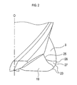
<コーナRすくい面>
図2に拡大して示すように、底刃すくい面19と切屑排出溝9との間には、底刃すくい面19と切屑排出溝9との間の部分の外周側をコーナR刃23に接するように切り欠いて、回転方向に面する壁面として、コーナRすくい面(即ちコーナRギャッシュ)27が設けられている。
図2に拡大して示すように、底刃すくい面19と切屑排出溝9との間には、底刃すくい面19と切屑排出溝9との間の部分の外周側をコーナR刃23に接するように切り欠いて、回転方向に面する壁面として、コーナRすくい面(即ちコーナRギャッシュ)27が設けられている。
なお、このコーナRすくい面27を形成する場合には、底刃すくい面19と切屑排出溝9との間(いわゆる稜線部分)を、外周端側に向かって削り取ることによって、なめからに湾曲して外周端に到るように形成することができる。
なお、稜線部分が切り欠かれていない部分では、底刃すくい面19の端部と切屑排出溝9の端部とが接した稜線25となっている。
詳しくは、図3に示すように、コーナR刃23と底刃21との交点をA点とし、コーナR刃23と外周刃13との交点をB点としたときに、軸線Oを含むとともにB点を通る平面に対して垂直となる方向(図1の紙面に対して垂直の方向)から見た場合に、軸線Oに平行でA点を通るA直線(LA)と軸線Oに垂直でB点を通るB直線(LB)との交点をC点とする。さらに、A直線とB直線とコーナR刃23とで囲まれた領域を、C点とA点からB点までの直線(L1)の中点とを通るC直線(LC)で分割したときに、C直線で分割されたA点側の領域を領域A(RA)、B点側の領域を領域B(RB)とする。この場合に、コーナRすくい面27は、領域Aには存在せず、B点を含むとともに少なくとも領域Bに形成されている。
詳しくは、図3に示すように、コーナR刃23と底刃21との交点をA点とし、コーナR刃23と外周刃13との交点をB点としたときに、軸線Oを含むとともにB点を通る平面に対して垂直となる方向(図1の紙面に対して垂直の方向)から見た場合に、軸線Oに平行でA点を通るA直線(LA)と軸線Oに垂直でB点を通るB直線(LB)との交点をC点とする。さらに、A直線とB直線とコーナR刃23とで囲まれた領域を、C点とA点からB点までの直線(L1)の中点とを通るC直線(LC)で分割したときに、C直線で分割されたA点側の領域を領域A(RA)、B点側の領域を領域B(RB)とする。この場合に、コーナRすくい面27は、領域Aには存在せず、B点を含むとともに少なくとも領域Bに形成されている。
従って、コーナRすくい面27では、その外周端の切れ刃28は、領域B内にあるコーナRすくい面27の外周端の底刃21側の第1端部27aから、外周刃13側の第2端部27bに到るように形成されている。なお、第1実施形態では、第2端部27bはB点に一致している。
なお、前記軸線O及びB点を含む平面におけるコーナR刃23の形状としては、例えば半径1.5mmの円の一部(円弧)を採用できるが、それ以外に、外側に凸となるように滑らかに湾曲した円弧状の形状を採用できる。
つまり、コーナRすくい面27は、底刃21側にある領域Aではなく、B点を含むとともに少なくとも領域Bに存在するように、連続した滑らかな一つの面として形成されている。言い換えると、コーナRすくい面27の外縁部分(即ち外周端である切れ刃28)は、コーナR刃23のうち、領域Aではなく領域Bの外縁に形成されている。また、切れ刃28の外周刃13側の第2端部27bは、B点にまで至っている。
すなわち、コーナRすくい面27の外周端の切れ刃28は、底刃21とコーナR刃23との交点であるA点から離れた位置(詳しくは領域B内の位置である第1端部27a)を起点して、終点がB点に到るように形成されている。
なお、本第1実施形態では、底刃すくい面19と切屑排出溝9との間の外周側を切り欠くようにコーナRすくい面27が形成されている。よって、底刃すくい面19は、領域A及びコーナRすくい面27の底刃21側の端部に達している。
<アキシャルレーキ>
図4に拡大して示すように、本第1実施形態では、底刃すくい面19のなすアキシャルレーキ(θA)が、ポジティブ(+)である。なお、図4に、アキシャルレーキ(θA)のポジティブ(+)とネガティブ(-)を記す。
図4に拡大して示すように、本第1実施形態では、底刃すくい面19のなすアキシャルレーキ(θA)が、ポジティブ(+)である。なお、図4に、アキシャルレーキ(θA)のポジティブ(+)とネガティブ(-)を記す。
なお、アキシャルレーキ(θA)とは、底刃すくい面19の軸線方向における先端側(外周端)が、軸線Oに対してなす角度である。
詳しくは、底刃すくい面19のなすアキシャルレーキ(θA)が、+1°~+5°の範囲である。
詳しくは、底刃すくい面19のなすアキシャルレーキ(θA)が、+1°~+5°の範囲である。
<エンドレーキ>
図5に拡大して示すように、本第1実施形態では、底刃21のなすエンドレ-キ(θE)が、ネガティブ(-)の範囲の-5°~-10°である。なお、図5に、エンドレーキ(θE)のポジティブ(+)とネガティブ(-)を記す。
図5に拡大して示すように、本第1実施形態では、底刃21のなすエンドレ-キ(θE)が、ネガティブ(-)の範囲の-5°~-10°である。なお、図5に、エンドレーキ(θE)のポジティブ(+)とネガティブ(-)を記す。
なお、エンドレーキ(θE)とは、軸線Oに沿って先端側から見た場合に、軸中心(OC)から底刃21の外周端21aに到る直線(LE)と底刃21とのなす角度(θE)のことである。
[1-3.効果]
次に、本第1実施形態の効果について説明する。
[1-3.効果]
次に、本第1実施形態の効果について説明する。
(1)本第1実施形態では、コーナRすくい面27は、底刃21側にある領域Aではなく、外周刃13側にある領域Bに存在するとともにB点を含むように形成されている。言い換えると、コーナRすくい面27の外縁部分の切れ刃28は、コーナR刃23のうち、領域Aではなく領域Bの外縁に形成されており、切れ刃28はB点にまで至っている。そのため、切削加工の際にコーナR刃23に欠損が生じにくいという効果がある。
つまり、コーナRすくい面27は、その外周端の切れ刃28の第1端部27aは、底刃21とコーナR刃23との交点であるA点から離れた領域Bにあり、また、第2端部27bはB点と一致している。従って、切削加工の際には、コーナRすくい面27の第1端部27aには大きな切削負荷がかかりにくいので、コーナR刃23が欠損しにくいという利点がある。
(2)また、本第1実施形態では、底刃すくい面19のなすアキシャルレーキ(θA)が、ポジティブ(詳しくは+1°~+5°)であるので、溶着の発生を抑制でき、それによって、底刃21やコーナR刃23等の切れ刃の欠損の発生を抑制することができる。また、底刃すくい面19のなすアキシャルレーキ(θA)を、ポジティブとすることにより、切屑排出性が向上し、切屑の噛み込みを抑制でき、底刃やコーナR刃等の切れ刃の欠損の発生を抑制できる。
(3)しかも、セラミック製のラジアスエンドミル1の場合には、底刃すくい面19のなすアキシャルレーキ(θA)をポジティブにすると、溶着の発生を抑制できる反面、例えば超硬合金に比べて切れ刃の先端が欠損し易い傾向にあるが、本第1実施形態では、底刃21のなすエンドレ-キ(θE)を、-5°~-10°のようなネガティブとしてあるので、切れ刃の先端の欠損の発生を抑制することができる。
つまり、溶着の発生を抑制するとともに、総合的に切れ刃の欠損の発生を抑制できるという顕著な効果を奏する。
(4)さらに、本第1実施形態のラジアスエンドミル1は、単一のセラミック部品であるので、シャンク部5が金属である場合に比べて、非常に軽量であるという利点がある。
[1-4.実験例]
次に、実験例について説明する。
(4)さらに、本第1実施形態のラジアスエンドミル1は、単一のセラミック部品であるので、シャンク部5が金属である場合に比べて、非常に軽量であるという利点がある。
[1-4.実験例]
次に、実験例について説明する。
実験例1では、前記第1実施形態のラジアスエンドミルの試料として、アキシャルレーキをポジティブ(+1°~+5°の範囲内の例えば+3°)としたときに、エンドレーキを-5°、-10°とした各試料を作製した。
そして、各試料を用いて、被加工物(ALLOY718)に対し、切削速度600m/min、送り量0.03mm/t、切込みap(深さ)=0.5mm、ae(幅)=5mmの条件で、切削加工を行った。その結果、各試料とも、加工距離が49m以下では、溶着がなく、切れ刃の欠損がなかった。
なお、アキシャルレーキをネガティブ(例えば-1°)とした比較例(他の構成は前記各試料と同じ)では、前記加工距離に達する前に切れ刃の欠損が発生した。
また、実験例2では、前記第1実施形態のラジアスエンドミルの試料として、エンドレーキを-5°~-10°の範囲内の例えば-7°とし、アキシャルレーキを+1°、+5°とした各試料を作製した。
また、実験例2では、前記第1実施形態のラジアスエンドミルの試料として、エンドレーキを-5°~-10°の範囲内の例えば-7°とし、アキシャルレーキを+1°、+5°とした各試料を作製した。
そして、被加工物(ALLOY718)に対し、切削速度600m/min、送り量0.03mm/t、切込みap=0.5mm、ae=5mmの条件で、切削加工を行った。その結果、各試料とも、加工距離が49m以下では、溶着がなく、切れ刃の欠損がなかった。
さらに、実験例3では、前記第1実施形態のラジアスエンドミルの試料として、アキシャルレーキを+1°~+5°の範囲外で単にポジティブ(例えば+0.5°)とした試料(他の構成は実験例1と同じ)を作製し、前記実験例1と同様な条件で切削加工を行った。
この場合には、前記実験例1よりは効果は少ないものの、加工距離が42m以下では、切れ刃の欠損が見られなかった。つまり、実験例1の各試料と実験例3の試料とを、前記実験例1の条件で欠損に到るまで加工したところ、実験例1の各試料の方が実験例3の試料より加工距離が長かった。なお、アキシャルレーキをポジティブとする場合の上限としては、例えば+6°が挙げられる。
[1-5.文言の対応関係]
ここで、本第1実施形態と本開示との文言の対応関係について説明する。
[1-5.文言の対応関係]
ここで、本第1実施形態と本開示との文言の対応関係について説明する。
本第1実施形態の、ラジアスエンドミル1、エンドミル本体3、切屑排出溝9、外周刃13、ギャッシュ17、底刃すくい面19、底刃21、コーナR刃23、コーナRすくい面27は、それぞれ、本開示の、ラジアスエンドミル、エンドミル本体、切屑排出溝、外周刃、ギャッシュ、底刃すくい面、底刃、コーナR刃、コーナRすくい面の一例に相当する。
[2.第2実施形態]
次に、第2実施形態について説明するが、第1実施形態と同様な内容については、その説明を省略又は簡略化する。なお、第1実施形態と同様な構成については、同様な番号を用いて説明する。
[2.第2実施形態]
次に、第2実施形態について説明するが、第1実施形態と同様な内容については、その説明を省略又は簡略化する。なお、第1実施形態と同様な構成については、同様な番号を用いて説明する。
図6に示すように、本第2実施形態のラジアスエンドミル31は、第1実施形態の切刃部7とほぼ同様な構成を有している。
具体的には、前記第1実施形態と同様に、コーナR刃23と底刃21との交点をA点とし、コーナR刃23と外周刃13との交点をB点としたときに、軸線Oを含むとともにB点を通る平面に対して垂直となる方向から見た場合に、軸線Oに平行でA点を通るA直線(LA)と軸線Oに垂直でB点を通るB直線(LB)との交点をC点とする。さらに、A直線とB直線とコーナR刃23とで囲まれた領域を、C点とA点からB点までの直線(L1)の中点とを通るC直線(LB)で分割したときに、C直線で分割されたA点側の領域を領域A(RA)、B点側の領域を領域B(RB)とする。
具体的には、前記第1実施形態と同様に、コーナR刃23と底刃21との交点をA点とし、コーナR刃23と外周刃13との交点をB点としたときに、軸線Oを含むとともにB点を通る平面に対して垂直となる方向から見た場合に、軸線Oに平行でA点を通るA直線(LA)と軸線Oに垂直でB点を通るB直線(LB)との交点をC点とする。さらに、A直線とB直線とコーナR刃23とで囲まれた領域を、C点とA点からB点までの直線(L1)の中点とを通るC直線(LB)で分割したときに、C直線で分割されたA点側の領域を領域A(RA)、B点側の領域を領域B(RB)とする。
そして、この場合に、コーナRすくい面27は、領域Aには存在せず、B点を含むとともに少なくとも領域Bに形成されている。しかも、コーナRすくい面27の外周端の切れ刃28の第2端部27bは、B点ではなくB点を超えて外周刃13側に形成されている。
なお、コーナRすくい面27の外周端の切れ刃28のうち、領域Bにある部分は、コーナR刃23の一部ということもでき、また、B点を超えて第2端部27bに到る部分は、外周刃13の一部ということもできる。
特に、本第2実施形態では、底刃すくい面19と切屑排出溝9との間に、第1実施形態とは形状の異なるコーナRすくい面27を有している。
つまり、コーナRすくい面27の外周刃28は、B点から更に外周刃13の一部(図6の上方に)に到るように形成されている。
つまり、コーナRすくい面27の外周刃28は、B点から更に外周刃13の一部(図6の上方に)に到るように形成されている。
本第2実施形態においても、前記第1実施形態と同様な効果を奏する。
[3.第3実施形態]
次に、第3実施形態について説明するが、第1実施形態と同様な内容については、その説明を省略又は簡略化する。なお、第1実施形態と同様な構成については、同様な番号を用いて説明する。
[3.第3実施形態]
次に、第3実施形態について説明するが、第1実施形態と同様な内容については、その説明を省略又は簡略化する。なお、第1実施形態と同様な構成については、同様な番号を用いて説明する。
図7、図8、図9に示すように、本第3実施形態のラジアスエンドミル41は、エンドミル本体43を備えた交換式ヘッド部45とシャンク部47とが、着脱可能に一体に接続されるヘッド交換式切削工具である。
詳しくは、前記エンドミル本体43は、第1実施形態と同様に、例えば窒化珪素等を用いて構成されたセラミック製であり、その先端側(図7の下方)に切刃部7を備えている。また、エンドミル本体43の後端側には、例えば鋼(例えば合金鋼)を用いて構成された本体側接続部49が一体に固定されている。
この本体側接続部49は、略円盤形状の基部51と、基部51の後端側から軸線Oに沿って後端側に突出する接続凸部53とを備えている。なお、接続凸部53の外周面の先端側に雄ねじ53aが形成されている。
また、エンドミル本体43の後端側には、軸線Oに沿って後端側に突出する角柱(例えば四角柱)の突出部55が形成されている。一方、基部51の先端側には、前記突出部55が嵌め込まれる角柱(例えば四角柱)状の空間である嵌合凹部57が形成されている。
そして、エンドミル本体43の突出部55が基部51の嵌合凹部57に嵌め込まれて、ろう材によって接合されることによって、エンドミル本体43と基部51(従って本体側接続部49)とが一体に固定されている。
なお、エンドミル本体43と本体側接続部49とが一体となった構成を、交換式ヘッド部45と称する。
一方、シャンク部47は、例えば鋼を用いて構成された棒状の部材であり、その先端側には、接続凸部53がねじ込まれる凹部であるシャンク側接続部59が構成されている。なお、シャンク側接続部59の内周面には、接続凸部53の雄ねじ53aと螺合する雌ねじ59aが形成されている。
一方、シャンク部47は、例えば鋼を用いて構成された棒状の部材であり、その先端側には、接続凸部53がねじ込まれる凹部であるシャンク側接続部59が構成されている。なお、シャンク側接続部59の内周面には、接続凸部53の雄ねじ53aと螺合する雌ねじ59aが形成されている。
なお、本体側接続部49の基部51の外周面には、互いに平行な2つの係止面61が形成されている。
従って、エンドミル本体43(従って交換式ヘッド部45)とシャンク部47とを一体に接続する場合には、本体側接続部49の接続凸部53をシャンク側接続部59にねじ込めばよい。なお、ねじ込む際には、基部51の2つの係止面61をレンチ等の工具で挟み、その工具をねじ込む方向に回すことによって、シャンク部47に対して交換式ヘッド部45を強固に固定することができる。
従って、エンドミル本体43(従って交換式ヘッド部45)とシャンク部47とを一体に接続する場合には、本体側接続部49の接続凸部53をシャンク側接続部59にねじ込めばよい。なお、ねじ込む際には、基部51の2つの係止面61をレンチ等の工具で挟み、その工具をねじ込む方向に回すことによって、シャンク部47に対して交換式ヘッド部45を強固に固定することができる。
本第3実施形態は、第1実施形態と同様な効果を奏する。
また、ラジアスエンドミル41による加工によって、エンドミル本体43の先端側が、摩耗や破損した場合には、交換式ヘッド部45のみをシャンク部47から取り外して交換することができる。
また、ラジアスエンドミル41による加工によって、エンドミル本体43の先端側が、摩耗や破損した場合には、交換式ヘッド部45のみをシャンク部47から取り外して交換することができる。
なお、本第3実施形態のように、交換式ヘッド部45とシャンク部47とを、着脱可能に接続する構成は、第2実施形態にも適用できる。
[4.他の実施形態]
本開示は前記実施形態になんら限定されるものではなく、本開示を逸脱しない範囲において種々の態様で実施しうることはいうまでもない。
[4.他の実施形態]
本開示は前記実施形態になんら限定されるものではなく、本開示を逸脱しない範囲において種々の態様で実施しうることはいうまでもない。
(1)例えば、コーナRすくい面の形成範囲については、前記実施形態に限定されることなく、本開示の範囲内において、自由に設定することができる。
(2)また、エンドミル本体やラジアスエンドミルの材料のセラミックとしては、窒化珪素、サイアロン、アルミナ、ジルコニアなどが挙げられる。
(2)また、エンドミル本体やラジアスエンドミルの材料のセラミックとしては、窒化珪素、サイアロン、アルミナ、ジルコニアなどが挙げられる。
(3)上記各実施形態における1つの構成要素が有する機能を複数の構成要素に分担させたり、複数の構成要素が有する機能を1つの構成要素に発揮させたりしてもよい。また、上記各実施形態の構成の一部を、省略してもよい。また、上記各実施形態の構成の少なくとも一部を、他の実施形態の構成に対して付加、置換等してもよい。なお、特許請求の範囲に記載の文言から特定される技術思想に含まれるあらゆる態様が本開示の実施形態である。
Claims (10)
- 軸線回りに回転されるラジアスエンドミルの先端側を構成する、セラミック製のエンドミル本体において、
前記エンドミル本体の先端部外周に、先端側から後端側に向かうに従って回転方向の後方に捻れるように形成された切屑排出溝と、
前記切屑排出溝の外周側稜線に形成された外周刃と、
前記エンドミル本体の先端部から前記切屑排出溝に到るギャッシュと、
前記ギャッシュに形成された底刃すくい面と、
前記エンドミル本体の先端部に形成された底刃と、
前記底刃から前記外周刃にわたって、外側に凸となるように円弧状に設けられたコーナR刃と、
前記底刃すくい面と前記切屑排出溝との間に前記コーナR刃に接するように設けられたコーナRすくい面と、
を有し、
前記コーナR刃と前記底刃との交点をA点とし、前記コーナR刃と前記外周刃との交点をB点としたときに、前記軸線を含むとともに前記B点を通る平面に対して垂直となる方向から見た場合に、
前記軸線に平行で前記A点を通るA直線と前記軸線に垂直で前記B点を通るB直線との交点をC点とし、前記A直線と前記B直線と前記コーナR刃とで囲まれた領域を、前記C点と前記A点から前記B点までの直線の中点とを通るC直線で分割したときに、前記C直線で分割された前記A点側の領域を領域A、前記B点側の領域を領域Bとした場合に、
前記コーナRすくい面は、前記領域Aには存在せず、前記B点を含むとともに少なくとも前記領域Bに存在するように形成されている、
エンドミル本体。 - 前記底刃のなすエンドレ-キが、-5°~-10°であり、
前記底刃すくい面のなすアキシャルレーキが、ポジティブである、
請求項1に記載のエンドミル本体。 - 前記底刃すくい面のなすアキシャルレーキが、+1°~+5°である、
請求項2に記載のエンドミル本体。 - 軸線回りに回転されるラジアスエンドミルの先端側を構成する、セラミック製のエンドミル本体において、
前記エンドミル本体の先端部外周に、先端側から後端側に向かうに従って回転方向の後方に捻れるように形成された切屑排出溝と、
前記切屑排出溝の外周側稜線に形成された外周刃と、
前記エンドミル本体の先端部から前記切屑排出溝に到るギャッシュと、
前記ギャッシュに形成された底刃すくい面と、
前記エンドミル本体の先端部に形成された底刃と、
前記底刃から前記外周刃にわたって、外側に凸となるように円弧状に設けられたコーナR刃と、
を有し、
前記底刃のなすエンドレ-キが、-5°~-10°であり、
前記底刃すくい面のなすアキシャルレーキが、ポジティブである、
エンドミル本体。 - 前記底刃すくい面のなすアキシャルレーキが、+1°~+5°である、
請求項4に記載のエンドミル本体。 - 前記底刃すくい面と前記切屑排出溝との間に前記コーナR刃に接するように設けられたコーナRすくい面を有する、
請求項4又は5に記載のエンドミル本体。 - 前記エンドミル本体の後端側に、工作機械の回転軸に固定されるシャンク部に対して着脱可能に接続される本体側接続部を備えた、
請求項1~6のいずれか1項に記載のエンドミル本体。 - 先端側に被加工物の加工を行うエンドミル本体を備えるとともに、後端側に工作機械の回転軸に固定されるシャンク部を備えたラジアスエンドミルであって、
前記エンドミル本体として、前記請求項1~6のいずれか1項に記載のエンドミル本体を備えた、
ラジアスエンドミル。 - 前記ラジアスエンドミルは、セラミック製であり、
前記エンドミル本体と前記シャンク部とが、一体に構成されている、
請求項8に記載のラジアスエンドミル。 - 前記ラジアスエンドミルは、前記エンドミル本体と前記シャンク部とが着脱可能に接続されたものであり、
前記エンドミル本体は、自身の後端側に、前記シャンク部に対して着脱可能に接続される本体側接続部を備えた、
請求項8に記載のラジアスエンドミル。
Priority Applications (4)
| Application Number | Priority Date | Filing Date | Title |
|---|---|---|---|
| CN201780040959.XA CN109414769B (zh) | 2016-06-30 | 2017-06-29 | 端铣刀主体和圆角端铣刀 |
| EP17820302.2A EP3479941A4 (en) | 2016-06-30 | 2017-06-29 | TWO-SIZE CYLINDRICAL STRAWBERRY BODY AND TWO-SIZE CYLINDRICAL STRAWBERRY |
| JP2017559138A JP6483860B2 (ja) | 2016-06-30 | 2017-06-29 | エンドミル本体及びラジアスエンドミル |
| US16/312,447 US11000906B2 (en) | 2016-06-30 | 2017-06-29 | Endmill body and radius end mill |
Applications Claiming Priority (2)
| Application Number | Priority Date | Filing Date | Title |
|---|---|---|---|
| JP2016-130440 | 2016-06-30 | ||
| JP2016130440 | 2016-06-30 |
Publications (1)
| Publication Number | Publication Date |
|---|---|
| WO2018003948A1 true WO2018003948A1 (ja) | 2018-01-04 |
Family
ID=60787301
Family Applications (1)
| Application Number | Title | Priority Date | Filing Date |
|---|---|---|---|
| PCT/JP2017/024039 WO2018003948A1 (ja) | 2016-06-30 | 2017-06-29 | エンドミル本体及びラジアスエンドミル |
Country Status (5)
| Country | Link |
|---|---|
| US (1) | US11000906B2 (ja) |
| EP (1) | EP3479941A4 (ja) |
| JP (1) | JP6483860B2 (ja) |
| CN (1) | CN109414769B (ja) |
| WO (1) | WO2018003948A1 (ja) |
Cited By (1)
| Publication number | Priority date | Publication date | Assignee | Title |
|---|---|---|---|---|
| WO2019188135A1 (ja) * | 2018-03-27 | 2019-10-03 | 日本特殊陶業株式会社 | エンドミル本体及びエンドミル |
Families Citing this family (2)
| Publication number | Priority date | Publication date | Assignee | Title |
|---|---|---|---|---|
| JP6483860B2 (ja) * | 2016-06-30 | 2019-03-13 | 日本特殊陶業株式会社 | エンドミル本体及びラジアスエンドミル |
| CN109794634A (zh) * | 2019-03-05 | 2019-05-24 | 苏州阿诺精密切削技术有限公司 | 一种粗加工整体陶瓷铣刀 |
Citations (9)
| Publication number | Priority date | Publication date | Assignee | Title |
|---|---|---|---|---|
| JPS5731102B2 (ja) | 1974-07-17 | 1982-07-02 | ||
| JPH07241715A (ja) * | 1993-06-25 | 1995-09-19 | Matsuura Kikai Seisakusho:Kk | セラミックスを素材とするエンドミル |
| JPH10249627A (ja) * | 1997-03-11 | 1998-09-22 | Daishowa Seiki Co Ltd | エンドミル |
| JP2003071626A (ja) * | 2001-08-30 | 2003-03-12 | Hitachi Tool Engineering Ltd | ラジアスエンドミル |
| JP2006297495A (ja) * | 2005-04-15 | 2006-11-02 | Dijet Ind Co Ltd | ラジアスエンドミル |
| JP2010201564A (ja) * | 2009-03-03 | 2010-09-16 | Mitsubishi Materials Corp | エンドミル |
| WO2013099954A1 (ja) * | 2011-12-27 | 2013-07-04 | 京セラ株式会社 | ラジアスエンドミル |
| JP2013215858A (ja) * | 2012-04-11 | 2013-10-24 | Dijet Industrial Co Ltd | ラジアスエンドミル |
| JP2014097574A (ja) * | 2014-03-03 | 2014-05-29 | Mitsubishi Materials Corp | ラジアスエンドミル |
Family Cites Families (17)
| Publication number | Priority date | Publication date | Assignee | Title |
|---|---|---|---|---|
| US6846135B2 (en) * | 2002-03-25 | 2005-01-25 | Hitachi Tool Engineering Ltd. | Radius end mill having radius edge enhanced in resistance to chipping and fracture |
| DE10225481A1 (de) * | 2002-06-10 | 2003-12-18 | Sandvik Ab | Fräser mit Wiper-Radius |
| US7306411B2 (en) * | 2002-09-03 | 2007-12-11 | Mitsubishi Materials Corporation | Drill with groove width variation along the drill and double margin with a thinning section at the tip |
| JP4622520B2 (ja) * | 2002-12-26 | 2011-02-02 | 三菱マテリアル株式会社 | ラジアスエンドミル |
| DE20310713U1 (de) * | 2003-07-12 | 2003-09-18 | Fette Gmbh | Stirnfräser |
| CN2626655Y (zh) * | 2003-08-20 | 2004-07-21 | 深圳金洲硬质合金有限公司 | 一种整体铣刀 |
| SE530043C2 (sv) * | 2006-04-20 | 2008-02-12 | Sandvik Intellectual Property | Verktyg för spånavskiljande bearbetning samt del därtill |
| WO2007125613A1 (ja) * | 2006-04-28 | 2007-11-08 | Union Tool Co. | 回転切削工具 |
| FR2926480B1 (fr) * | 2008-01-23 | 2011-08-12 | Snecma | Fraise de surfacage et de detourage pour l'usinage a grande vitesse de pieces en materiau composite |
| JP5731102B2 (ja) | 2009-01-21 | 2015-06-10 | 三菱マテリアル株式会社 | ラジアスエンドミル |
| US9227253B1 (en) * | 2009-03-30 | 2016-01-05 | Steven M. Swift | Rotary cutter for machining materials |
| US8858128B2 (en) * | 2012-11-14 | 2014-10-14 | Iscar, Ltd. | Corner radius end mill |
| US9517515B2 (en) * | 2014-09-15 | 2016-12-13 | Iscar, Ltd. | End mill convex radial relief surface and corner having circular arc profile |
| CN107000080A (zh) * | 2015-02-27 | 2017-08-01 | 三菱综合材料株式会社 | 圆弧头立铣刀、球头立铣刀及立铣刀 |
| EP3272446A4 (en) * | 2015-03-20 | 2018-11-21 | Mitsubishi Hitachi Tool Engineering, Ltd. | Square end mill |
| CA2981151C (en) * | 2015-12-14 | 2019-09-10 | Alp Havacilik Sanayi Ve Ticaret Anonim Sirketi | End-mills made of hard metal and ceramic combined by brazing method |
| JP6483860B2 (ja) * | 2016-06-30 | 2019-03-13 | 日本特殊陶業株式会社 | エンドミル本体及びラジアスエンドミル |
-
2017
- 2017-06-29 JP JP2017559138A patent/JP6483860B2/ja active Active
- 2017-06-29 EP EP17820302.2A patent/EP3479941A4/en active Pending
- 2017-06-29 CN CN201780040959.XA patent/CN109414769B/zh active Active
- 2017-06-29 US US16/312,447 patent/US11000906B2/en active Active
- 2017-06-29 WO PCT/JP2017/024039 patent/WO2018003948A1/ja unknown
Patent Citations (9)
| Publication number | Priority date | Publication date | Assignee | Title |
|---|---|---|---|---|
| JPS5731102B2 (ja) | 1974-07-17 | 1982-07-02 | ||
| JPH07241715A (ja) * | 1993-06-25 | 1995-09-19 | Matsuura Kikai Seisakusho:Kk | セラミックスを素材とするエンドミル |
| JPH10249627A (ja) * | 1997-03-11 | 1998-09-22 | Daishowa Seiki Co Ltd | エンドミル |
| JP2003071626A (ja) * | 2001-08-30 | 2003-03-12 | Hitachi Tool Engineering Ltd | ラジアスエンドミル |
| JP2006297495A (ja) * | 2005-04-15 | 2006-11-02 | Dijet Ind Co Ltd | ラジアスエンドミル |
| JP2010201564A (ja) * | 2009-03-03 | 2010-09-16 | Mitsubishi Materials Corp | エンドミル |
| WO2013099954A1 (ja) * | 2011-12-27 | 2013-07-04 | 京セラ株式会社 | ラジアスエンドミル |
| JP2013215858A (ja) * | 2012-04-11 | 2013-10-24 | Dijet Industrial Co Ltd | ラジアスエンドミル |
| JP2014097574A (ja) * | 2014-03-03 | 2014-05-29 | Mitsubishi Materials Corp | ラジアスエンドミル |
Non-Patent Citations (1)
| Title |
|---|
| See also references of EP3479941A4 * |
Cited By (3)
| Publication number | Priority date | Publication date | Assignee | Title |
|---|---|---|---|---|
| WO2019188135A1 (ja) * | 2018-03-27 | 2019-10-03 | 日本特殊陶業株式会社 | エンドミル本体及びエンドミル |
| JPWO2019188135A1 (ja) * | 2018-03-27 | 2021-02-12 | 日本特殊陶業株式会社 | エンドミル本体及びエンドミル |
| JP7341058B2 (ja) | 2018-03-27 | 2023-09-08 | Ntkカッティングツールズ株式会社 | エンドミル本体及びエンドミル |
Also Published As
| Publication number | Publication date |
|---|---|
| EP3479941A1 (en) | 2019-05-08 |
| JPWO2018003948A1 (ja) | 2018-06-28 |
| JP6483860B2 (ja) | 2019-03-13 |
| US11000906B2 (en) | 2021-05-11 |
| EP3479941A4 (en) | 2020-04-01 |
| CN109414769B (zh) | 2020-12-22 |
| CN109414769A (zh) | 2019-03-01 |
| US20200030895A1 (en) | 2020-01-30 |
Similar Documents
| Publication | Publication Date | Title |
|---|---|---|
| WO2015060392A1 (ja) | ボールエンドミル | |
| JP6483860B2 (ja) | エンドミル本体及びラジアスエンドミル | |
| JP2008093805A (ja) | ドリル | |
| JP5194637B2 (ja) | エンドミル | |
| JP2007030074A (ja) | ラジアスエンドミル及び切削加工方法 | |
| WO2010084805A1 (ja) | ラジアスエンドミル | |
| JP7341058B2 (ja) | エンドミル本体及びエンドミル | |
| CN110418690A (zh) | 具有圆弧轮廓的用于加工铬镍铁合金的陶瓷面铣刀 | |
| KR20080114782A (ko) | 엔드 밀 | |
| JP2003300112A (ja) | スクエアエンドミル | |
| JP2009056534A (ja) | 座ぐり加工用ドリル | |
| WO2015137508A1 (ja) | 切削インサート、工具ボデーおよび切削工具 | |
| JP2005125465A (ja) | エンドミル | |
| JP2006015418A (ja) | 縦送り加工用エンドミル | |
| JP2010201565A (ja) | エンドミル | |
| JPH06335816A (ja) | 極小径エンドミル | |
| JP2009034735A (ja) | 3溝ドリル | |
| JP2007283467A (ja) | 切削インサート及び切削工具 | |
| JP5219671B2 (ja) | 内径加工用切削工具並びにそれを用いた切削方法 | |
| JP5560748B2 (ja) | 刃先交換式溝入れ工具及び周面溝入れ加工方法 | |
| JP2006026839A (ja) | ラジアスエンドミル | |
| JP2002326113A (ja) | バリ取りカッター | |
| JP2005279899A (ja) | エンドミル | |
| JP3307694B2 (ja) | エンドミル | |
| JP2009226533A (ja) | クリスマスカッタ |
Legal Events
| Date | Code | Title | Description |
|---|---|---|---|
| ENP | Entry into the national phase |
Ref document number: 2017559138 Country of ref document: JP Kind code of ref document: A |
|
| 121 | Ep: the epo has been informed by wipo that ep was designated in this application |
Ref document number: 17820302 Country of ref document: EP Kind code of ref document: A1 |
|
| NENP | Non-entry into the national phase |
Ref country code: DE |
|
| ENP | Entry into the national phase |
Ref document number: 2017820302 Country of ref document: EP Effective date: 20190130 |