WO2017217543A1 - アライメント方法及びアライメント装置 - Google Patents
アライメント方法及びアライメント装置 Download PDFInfo
- Publication number
- WO2017217543A1 WO2017217543A1 PCT/JP2017/022373 JP2017022373W WO2017217543A1 WO 2017217543 A1 WO2017217543 A1 WO 2017217543A1 JP 2017022373 W JP2017022373 W JP 2017022373W WO 2017217543 A1 WO2017217543 A1 WO 2017217543A1
- Authority
- WO
- WIPO (PCT)
- Prior art keywords
- substrate
- alignment
- resin material
- curing
- plate
- Prior art date
- Legal status (The legal status is an assumption and is not a legal conclusion. Google has not performed a legal analysis and makes no representation as to the accuracy of the status listed.)
- Ceased
Links
Images






Classifications
-
- B—PERFORMING OPERATIONS; TRANSPORTING
- B32—LAYERED PRODUCTS
- B32B—LAYERED PRODUCTS, i.e. PRODUCTS BUILT-UP OF STRATA OF FLAT OR NON-FLAT, e.g. CELLULAR OR HONEYCOMB, FORM
- B32B38/00—Ancillary operations in connection with laminating processes
- B32B38/18—Handling of layers or the laminate
-
- B—PERFORMING OPERATIONS; TRANSPORTING
- B32—LAYERED PRODUCTS
- B32B—LAYERED PRODUCTS, i.e. PRODUCTS BUILT-UP OF STRATA OF FLAT OR NON-FLAT, e.g. CELLULAR OR HONEYCOMB, FORM
- B32B37/00—Methods or apparatus for laminating, e.g. by curing or by ultrasonic bonding
- B32B37/12—Methods or apparatus for laminating, e.g. by curing or by ultrasonic bonding characterised by using adhesives
-
- B—PERFORMING OPERATIONS; TRANSPORTING
- B32—LAYERED PRODUCTS
- B32B—LAYERED PRODUCTS, i.e. PRODUCTS BUILT-UP OF STRATA OF FLAT OR NON-FLAT, e.g. CELLULAR OR HONEYCOMB, FORM
- B32B41/00—Arrangements for controlling or monitoring lamination processes; Safety arrangements
-
- B—PERFORMING OPERATIONS; TRANSPORTING
- B32—LAYERED PRODUCTS
- B32B—LAYERED PRODUCTS, i.e. PRODUCTS BUILT-UP OF STRATA OF FLAT OR NON-FLAT, e.g. CELLULAR OR HONEYCOMB, FORM
- B32B7/00—Layered products characterised by the relation between layers; Layered products characterised by the relative orientation of features between layers, or by the relative values of a measurable parameter between layers, i.e. products comprising layers having different physical, chemical or physicochemical properties; Layered products characterised by the interconnection of layers
- B32B7/04—Interconnection of layers
- B32B7/12—Interconnection of layers using interposed adhesives or interposed materials with bonding properties
-
- H—ELECTRICITY
- H10—SEMICONDUCTOR DEVICES; ELECTRIC SOLID-STATE DEVICES NOT OTHERWISE PROVIDED FOR
- H10P—GENERIC PROCESSES OR APPARATUS FOR THE MANUFACTURE OR TREATMENT OF DEVICES COVERED BY CLASS H10
- H10P72/00—Handling or holding of wafers, substrates or devices during manufacture or treatment thereof
- H10P72/70—Handling or holding of wafers, substrates or devices during manufacture or treatment thereof for supporting or gripping
Definitions
- the present invention relates to an alignment method and an alignment apparatus.
- designated countries that are permitted to be incorporated by reference, Japanese Patent Application No. 2016-120513 filed in Japan on June 17, 2016, and Japanese Patent Application filed in Japan on June 17, 2016
- the content described in 2016-120514 is incorporated herein by reference and made a part of the description of this specification.
- a technique is known in which a base glass is pressed against a bonding target with an adhesive roller in a state where the bonding target and the base glass are positioned with high accuracy (for example, see Patent Document 1).
- the problem to be solved by the present invention is to provide an alignment method and an alignment apparatus capable of improving the alignment accuracy between the first substrate and the second substrate.
- An alignment method includes a preparation step of preparing an alignment target object in which a first substrate and a second substrate are stacked via an uncured resin material, and the uncured state In a state where a resin material is interposed between the first substrate and the second substrate, the relative position of the second substrate with respect to the first substrate is detected, and based on the detection result, An alignment step of mutually aligning the first substrate and the second substrate, and a curing step of curing the uncured resin material after the alignment step is started, the alignment step comprising:
- the alignment method includes a first alignment step of moving at least one of the first substrate and the second substrate in a planar direction.
- the method further includes a holding step of sandwiching the alignment target object between the first plate and the second plate after the preparation step and before the alignment step,
- the first plate includes holding the first substrate and holding the second substrate on the second plate, and the first alignment step includes the first plate and the second plate. Moving at least one of the plates in the planar direction and moving at least one of the first substrate and the second substrate in the planar direction.
- the curing step at least a part of the uncured resin material is cured, and the first substrate and the second substrate are maintained in a mutually aligned state.
- the whole of the uncured resin material is cured, and the second curing step of fixing the first substrate and the second substrate to each other And may be included.
- the uncured resin material is interposed between the first substrate and the second substrate, and the first substrate and the second substrate are captured by the imaging unit. It may include imaging the second substrate and detecting the relative position.
- the alignment step includes simultaneously imaging the first pattern of the first substrate and the second pattern of the second substrate within the same field of view of the imaging means. May be included.
- the alignment step is performed until the first pattern of the first substrate and the second pattern of the second substrate substantially coincide with each other.
- the curing step is performed when the first pattern of the first substrate and the second pattern of the second substrate substantially coincide with each other. Also good.
- the imaging means may be fixed to the first plate.
- the first plate may have a first opening through which an optical axis of the imaging means passes.
- the imaging means may be fixed to the first plate so as to face the first opening.
- a part of the uncured resin material may be cured and the curing means may be fixed to the first plate.
- the first plate may have a second opening through which energy rays irradiated from the curing means pass.
- the curing means may be fixed to the first plate so as to face the second opening.
- the first substrate may be a transparent substrate capable of transmitting visible light.
- the first alignment step at least one of the first substrate and the second substrate is set so that the relative position corresponds to a predetermined target position in plan view.
- the curing step may be performed when the relative position and the target position correspond to each other in a plan view.
- the alignment step in the state where the uncured resin material is interposed between the first substrate and the second substrate, the second substrate with respect to the first substrate.
- the first substrate and the second substrate are arranged so that the relative position corresponds to the target position by causing the relative shape to correspond to a predetermined target shape in a plan view.
- the curing step may be performed when the relative shape corresponds to the target shape in plan view, including adjusting at least one temperature.
- the second alignment step includes adjusting the temperature of at least one of the first substrate and the second substrate for each of a plurality of temperature control regions partitioned in a plan view. You may go out.
- the alignment object is sandwiched between the first plate and the second plate after the preparation step and before the alignment step, A holding step of holding the first substrate and holding the first substrate on the second plate, and the uncured resin material between the first substrate and the second substrate Adjusting the thickness of the uncured resin material by adjusting the thickness of the uncured resin material by bringing the first plate and the second plate closer to or away from each other with the intervening material interposed therebetween, and the curing step After the adjustment process is started, the uncured resin material may be cured.
- the curing step includes a first curing step of curing at least a part of the uncured resin material and maintaining a state in which the thickness of the uncured resin material is adjusted. And after the first curing step, a second curing step of curing the entire uncured resin material and fixing the first substrate and the second substrate to each other. You may go out.
- the adjusting step estimates the amount of thermal strain generated in the uncured resin material by adjusting the temperature of at least one of the first substrate and the second substrate. And adjusting the thickness of the uncured resin material by moving the first plate and the second plate closer to or away from each other based on the thermal strain amount. .
- the adjustment step may be performed on the uncured resin material based on a pressing force applied to the uncured resin material from the first plate and the second plate. Estimating the amount of elastic deformation that occurs, and adjusting the thickness of the uncured resin material by moving the first plate and the second plate closer to or away from each other based on the amount of elastic deformation And may include.
- the adjusting step is based on estimating a curing shrinkage amount generated in the resin material when the uncured resin material is cured, and based on the curing shrinkage amount, Adjusting the thickness of the uncured resin material by bringing the first plate and the second plate closer to or away from each other.
- An alignment apparatus includes a first plate that holds a first substrate, a second plate that is disposed opposite to the first plate and holds a second substrate, A first moving means for moving at least one of the first plate and the second plate in a planar direction; a curing means for performing a curing process for curing an uncured resin material; and the uncured state Position detecting means for detecting a relative positional relationship between the first substrate and the second substrate in a state where a resin material is interposed between the first substrate and the second substrate; Control means for controlling the first moving means and the curing means, wherein the control means interposes the uncured resin material between the first substrate and the second substrate.
- the alignment apparatus may further include second moving means for moving the first plate and the second plate closer to or away from each other.
- control means cures at least a part of the uncured resin material, and maintains the state in which the first substrate and the second substrate are aligned with each other.
- the curing means may be controlled.
- the position detection means may be configured such that the uncured resin material is interposed between the first substrate and the second substrate, and the first substrate and the first substrate An imaging means for imaging the two substrates may be included.
- the imaging means may simultaneously image the first pattern of the first substrate and the second pattern of the second substrate within the same field of view.
- the imaging means may be configured such that the first substrate and the first substrate until the first pattern of the first substrate substantially matches the second pattern of the second substrate.
- the control unit performs the curing process when the first pattern of the first substrate and the second pattern of the second substrate substantially coincide with each other.
- the curing means may be controlled.
- the imaging means may be fixed to the first plate.
- the first plate may have a first opening through which an optical axis of the imaging means passes.
- the imaging means may be fixed to the first plate so as to face the first opening.
- the curing means may be fixed to the first plate.
- the first plate may have a second opening through which energy rays irradiated from the curing means pass.
- the curing means may be fixed to the first plate so as to face the second opening.
- the first substrate may be a transparent substrate capable of transmitting visible light.
- control means moves at least one of the first substrate and the second substrate in a planar direction, and the relative position corresponds to a predetermined target position in plan view.
- the first moving unit may be controlled as described above, and the curing unit may be controlled to perform the curing process when the relative position corresponds to the target position in plan view.
- the alignment apparatus further includes temperature adjusting means for adjusting a temperature of at least one of the first substrate and the second substrate, and the position detecting means is in the uncured state.
- the control means is configured to detect the first substrate.
- the temperature of at least one of the substrate and the second substrate is adjusted, and the relative shape is made to correspond to a predetermined target shape in plan view so that the relative position corresponds to the target position.
- the adjusting means may be controlled, and the curing means may be controlled to perform the curing process when the relative shape corresponds to the target shape in plan view.
- the temperature adjustment means may adjust the temperature of at least one of the first substrate and the second substrate for each of a plurality of temperature adjustment regions partitioned in a plan view.
- the alignment device detects the thickness of the uncured resin material, and second moving means for bringing the first plate and the second plate closer to or away from each other.
- a thickness detecting means for controlling the second moving means and the curing means based on a detection result of the thickness detecting means, and the control means is configured to control the uncured With the resin material in a state interposed between the first substrate and the second substrate, the first plate and the second plate are moved closer to or away from each other, and the uncured state
- the second moving unit is controlled to adjust the thickness of the resin material, and the curing unit is controlled to perform the curing process after the adjustment of the thickness of the uncured resin material is started.
- control means hardens at least a part of the uncured resin material and maintains the cured state so that the thickness of the uncured resin material is adjusted.
- the means may be controlled.
- the alignment apparatus is configured to adjust the temperature of at least one of the first substrate and the second substrate by the temperature adjusting means, and thereby generate thermal strain in the uncured resin material.
- First estimation means for estimating the amount, wherein the control means causes the first plate and the second plate to approach or separate from each other based on the thermal strain amount, and the uncured state
- the second moving means may be controlled so as to adjust the thickness of the resin material.
- the alignment device includes: a pressure detection unit that detects a pressing force applied to the uncured resin material from the first plate and the second plate; Second estimation means for estimating an elastic deformation amount generated in the uncured resin material based on a detection result, and the control means is configured to determine the first deformation based on the elastic deformation amount.
- the second moving means may be controlled so as to adjust the thickness of the uncured resin material by moving the plate and the second plate closer to or away from each other.
- the alignment apparatus further includes third estimation means for estimating a curing shrinkage amount generated in the resin material when the uncured resin material is cured, and the control means Based on the amount of cure shrinkage, the second plate moves the first plate and the second plate closer to or away from each other and adjusts the thickness of the uncured resin material.
- the means may be controlled.
- the first substrate and the second substrate is moved in the plane direction, and the first substrate and the second substrate are moved. They are aligned with each other. For this reason, the positional displacement due to the overlapping of the first substrate and the second substrate does not occur, and the alignment accuracy between the first substrate and the second substrate can be improved.
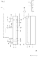
- FIG. 1 is a side view of an alignment apparatus according to an embodiment of the present invention.
- FIG. 2 is a view of the upper plate according to the embodiment of the present invention as viewed from the first holding surface side.
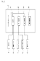
- FIG. 3 is a block diagram showing a control unit according to an embodiment of the present invention.
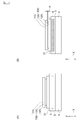
- 4 (A) and 4 (B) are side views for explaining the amount of thermal strain.
- FIG. 5A and FIG. 5B are side views for explaining the amount of elastic deformation.
- 6A and 6B are side views for explaining the curing shrinkage.
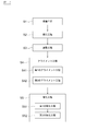
- FIG. 7 is a process diagram showing an alignment method according to an embodiment of the present invention.
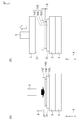
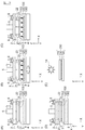
- FIGS. 8A to 8F are side views for explaining (part 1) the alignment method according to the embodiment of the present invention.
- FIGS. 9A to 9E are side views for explaining (part 2) the alignment method according to the embodiment of the present invention.
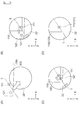
- FIGS. 10A to 10D are partially enlarged plan views for explaining (part 3) the alignment method according to the embodiment of the present invention.
- FIG. 11 is an exploded perspective view showing an alignment object according to an embodiment of the present invention.
- FIG. 12 is a plan view of the alignment target as viewed from the first substrate side.
- FIGS. 13A and 13B are side views for explaining an alignment method according to another embodiment of the present invention.
- FIG. 14 is a plan view showing a lower plate and a temperature control unit according to another embodiment of the present invention.
- FIG. 1 is a side view of an alignment apparatus according to an embodiment of the present invention.
- the alignment apparatus 1 shown in FIG. 1 is an apparatus for mounting the alignment target object 100 and relatively aligning the first substrate 110 and the second substrate 120 included in the alignment target object 100.
- the alignment target object 100 will be described in detail with reference to FIGS. 11 and 12.
- FIG. 11 is an exploded perspective view showing an alignment target object according to an embodiment of the present invention
- FIG. 12 is a plan view showing the alignment target object as viewed from the first substrate side.
- the alignment target object 100 includes a first substrate 110, a second substrate 120 overlaid on the first substrate, and between the first substrate 110 and the second substrate 120. And an uncured resin material 130 interposed between the two.
- “Alignment object 100” in the present embodiment corresponds to an example of “alignment object” in the present invention
- first substrate 110 in the present embodiment corresponds to an example of “first substrate” in the present invention.
- the “second substrate 120” in the present embodiment corresponds to an example of the “second substrate” in the present invention
- the “resin material 130” in the present embodiment corresponds to an example of the “resin material” in the present invention. To do.
- the first substrate 110 is a transparent rectangular substrate that can transmit visible light and ultraviolet rays.
- the first substrate 110 is made of a transparent material. Is done.
- the material constituting the first substrate 110 include polyethylene terephthalate (PET), polyethylene naphthalate (PEN), polyethylene (PE), ethylene-vinyl acetate copolymer (EVA), and polystyrene (PS).
- the first substrate 110 may be formed by stacking a plurality of the above materials, or may be stacked by functional layers.
- the first substrate 110 has a first pattern 111 that is an alignment mark used for alignment between the first substrate 110 and the second substrate 120.
- the first pattern 111 is located diagonally to the first substrate 110 in plan view. Note that the arrangement, shape, and number of the first patterns 111 are not particularly limited to those described above. In the present embodiment, the number of the first patterns 111 is two, but four first patterns 111 may be provided corresponding to each corner of the first substrate 110 in plan view. Good. Alternatively, four first patterns 111 are provided corresponding to each corner of the first substrate 110, and four first patterns 111 are provided corresponding to the centers of the sides of the first substrate 110, One first pattern 111 may be provided at the center of the first substrate 110 (in this case, a total of nine first patterns 111 are provided).
- the second substrate 120 is a rectangular substrate.
- the material constituting the second substrate 120 include polyethylene terephthalate (PET), polyethylene naphthalate (PEN), polyethylene (PE), ethylene-vinyl acetate copolymer (EVA), polystyrene (PS), and ABS resin.
- Vinyl chloride (PVC) polyimide resin (PI), polyetherimide resin (PEI), polycarbonate (PC), polyetheretherketone (PEEK), liquid crystal polymer (LCP), cycloolefin polymer (COP), silicone resin ( SI), resin materials such as acrylic resin (PMMA), phenol resin, and epoxy resin, metal materials such as stainless steel and titanium, inorganic materials such as ceramic material and glass, and the like can be used.
- the resin material may be a material that can transmit visible light, or a material that cannot transmit visible light (opaque).
- the second substrate 120 may be formed by stacking a plurality of the above materials, or may be formed by stacking functional layers.
- the second substrate 120 when the imaging unit 6 is arranged on the side where the second substrate 120 is located with respect to the resin material 130, the second substrate 120 is made of a transparent material.
- the first substrate 110 may use an opaque material.
- the first substrate 110 and the second substrate 120 may use a transparent material or an opaque material. It may be used.
- the second substrate 120 is arranged to overlap the first substrate 110 in plan view.
- the second substrate 120 has a second pattern 121 that is an alignment mark used for alignment between the first substrate 110 and the second substrate 120.
- the second pattern 121 is arranged according to the first pattern 111 and is located at the diagonal of the second substrate 120 in plan view.
- the second pattern 121 is located outside the corresponding first pattern 111 in plan view. Note that the arrangement, shape, and number of the second patterns 121 are not particularly limited.
- the arrangement of the second pattern 121 is set according to the temperature adjustment by the temperature adjustment unit 8.
- the first pattern 111 and the second pattern 121 are formed so as to be imaged by the imaging unit 6 of the alignment apparatus 1 described later.
- the first pattern 111 and the second pattern 121 can be formed using, for example, a known printing method.
- the method for forming the first pattern 111 and the second pattern 121 is not particularly limited to the above.
- the second pattern 121 may be formed by printing, and the first pattern 111 may be configured by a through hole including the second pattern 121.
- the first substrate 110 may not be formed of a transparent material that can transmit visible light.
- the “pattern” in the present embodiment includes a mark printed on the substrate and a through-hole formed in the substrate.
- the thermal expansion coefficient of the first substrate 110 and the thermal expansion coefficient of the second substrate 120 are different from each other. Specifically, when a glass plate is used as the first substrate 110, the thermal expansion coefficient of the material constituting the glass plate is 2 ⁇ 10 ⁇ 6 / ° C., whereas the second substrate is When a stainless steel plate is used, the thermal expansion coefficient of the material constituting the stainless steel plate is 10 ⁇ 10 ⁇ 6 / ° C. The thermal expansion coefficient of the material constituting the second substrate 120 is relatively large with respect to the thermal expansion coefficient of the material constituting the first substrate 110.
- the thermal expansion coefficient of the material constituting the second substrate 120 is relatively larger than the thermal expansion coefficient of the material constituting the first substrate 110, and the second substrate is formed by the temperature adjustment unit 8.
- the second pattern 121 is positioned inside the corresponding first pattern 111 in plan view.
- the resin material 130 is interposed between the first substrate 110 and the second substrate 120.
- the resin material 130 is provided in layers between the first substrate 110 and the second substrate 120.
- Such a resin material 130 is a transparent material that transmits visible light and is made of a material that is fluid in an uncured state.
- the viscosity of the uncured resin material 130 is preferably 10 cP to 150,000 cP, and more preferably 1,000 cP to 10,000 cP.
- a material that is fluid in an uncured state means that the viscosity of the material is within the above-mentioned viscosity range and causes irreversible deformation by an external force.
- a conventionally known material such as an ultraviolet curable adhesive material, a thermosetting adhesive material, or a curable adhesive material such as a two-component curable adhesive material can be used. It is preferable to use a resin material such as an epoxy resin, a silicone resin, or an acrylic resin.
- the alignment object 100 is used to obtain a stacked body 200 (see FIG. 9E) in which the first substrate 110 and the second substrate 120 are stacked.
- the laminated body 200 has an adhesive portion 230 formed by curing the entire resin material 130 between the first substrate 110 and the second substrate 120.
- the bonding portion 230 has a function of fixing the first substrate 110 and the second substrate 120 to each other.
- FIGS. 2 is a view of the upper plate according to the embodiment of the present invention as viewed from the first holding surface side
- FIG. 3 is a block diagram showing the control unit according to the embodiment of the present invention
- FIG. 4B is a side view for explaining the amount of thermal strain
- FIGS. 5A and 5B are side views for explaining the amount of elastic deformation
- FIGS. 6A and 6B. B) is a side view for explaining the amount of cure shrinkage.
- the alignment apparatus 1 includes an upper plate 2, a lower plate 3, a first moving unit 4, a second moving unit 5, an imaging unit 6, a curing unit 7, and a temperature control.
- a unit 8, a control unit 9, a distance sensor 10, a first temperature sensor 11, a second temperature sensor 12, and a pressure sensor 13 are provided.
- the “alignment apparatus 1” in the present embodiment corresponds to an example of the “alignment apparatus” in the present invention
- the “upper plate 2” in the present embodiment corresponds to an example of the “first plate” in the present invention
- the “lower plate 3” in the embodiment corresponds to an example of the “second plate” in the present invention
- the “first moving unit 4” in the present embodiment corresponds to an example of the “first moving unit” in the present invention.
- the “second moving unit 5” in the present embodiment corresponds to an example of the “second moving unit” in the present invention
- the “imaging unit 6” in the present embodiment is the “position detecting unit” in the present invention.
- curing part 7 in this embodiment corresponds to an example of “curing means” in the present invention
- temperature control part 8 in this embodiment corresponds to an example of “temperature adjusting means” in the present invention.
- this implementation “Distance sensor 10" in the state corresponds to an example of the “distance detection means” in the present invention
- the pressure sensor 13 in this embodiment corresponds to an example of the "pressure detecting means” of the present invention.
- the upper plate 2 is a substantially rectangular plate-like member for holding the first substrate 110.
- the upper plate 2 is disposed so as to be substantially parallel to the horizontal plane.
- the main surface facing the lower plate 3 is a first holding surface 21 that can hold the first substrate 110.
- a plurality of suction ports are opened in the first holding surface 21 so that the first substrate 110 can be fixed by suction.
- a suction means (not shown), a vacuum pump connected to a plurality of suction ports can be used.
- the method for fixing the first substrate 110 to the upper plate 2 is not particularly limited to the above.
- a plurality of imaging through holes 22 (in this embodiment, which enables imaging of the first pattern 111 and the second pattern 121 by a plurality of imaging units 6 (two in this embodiment). Two).
- the two imaging through holes 22 are located diagonally of the rectangular upper plate 2.
- the number and arrangement of the imaging through holes 22 are set according to the number and arrangement of the imaging units 6.
- the “imaging through hole 22” in the present embodiment corresponds to an example of the “first opening” in the present invention.
- the imaging unit 6 may be embedded in the upper plate 2, and in this case, the imaging through hole 22 is a surface of the upper plate 2 that faces the lower plate 3 (that is, the first holding of the upper plate 2). It is constituted by a non-penetrating opening formed in the surface 21).
- the upper plate 2 is provided with a plurality of irradiation openings 23 that can irradiate energy rays such as ultraviolet rays that cure the uncured resin material 130 by the curing unit 7.
- the irradiation amount opening 23 opens on the surface of the lower plate 3 facing the upper plate 32 (that is, the second holding surface 31 of the lower plate 3).
- twelve irradiation openings 23 are formed in a matrix.
- the distance between the adjacent irradiation openings 23 depends on the size of the first substrate 110 and the second substrate 120, but is about 50 mm in this embodiment.
- the number of the irradiation openings 23 and the interval between the irradiation openings 23 are not particularly limited.
- the “irradiation opening 23” in the present embodiment corresponds to an example of a “second opening” in the present invention.
- the imaging through-hole 22 may not be provided. Further, as a method of curing the uncured resin material 130, when energy rays such as ultraviolet rays are used, and the upper plate 2 is made of a material that can transmit the energy rays, the irradiation opening 23 is It does not have to be provided.
- the lower plate 3 is a substantially rectangular plate-like member for holding the second substrate 120.
- the lower plate 3 is disposed so as to be substantially parallel to the upper plate 2.
- the parallelism between the first holding surface 21 of the upper plate 2 and the second holding surface 31 of the lower plate 3 to be described later is preferably ⁇ 10 ⁇ m or less.
- the main surface facing the upper plate 2 is a second holding surface 31 on which the second substrate 120 can be placed.
- a plurality of suction ports are opened in the second holding surface 31 so that the second substrate 120 can be sucked and fixed.
- a suction means (not shown), a vacuum pump connected to a plurality of suction ports can be used.
- the method for fixing the second substrate 120 to the lower plate 3 is not particularly limited to the above.
- the first moving unit 4 has a function of relatively moving the upper plate 2 and the lower plate 3 in the plane direction.
- an alignment stage that can move in the X direction, the Y direction, and the ⁇ direction is used.
- a moving mechanism of each axis (X direction, Y direction, and ⁇ direction) constituting the first moving unit 4 a moving mechanism including a ball screw mechanism and a motor can be used.
- a UVW stage may be used as the first moving unit 4.
- the first moving unit 4 of the present embodiment is connected to the lower plate 3.
- the upper plate 2 is fixed in the plane direction.
- the first moving unit 4 is operated and the lower plate 3 is moved in the plane direction, the upper plate 2 and the lower plate 3 can be relatively moved in the plane direction.
- the first moving unit 4 has a function of adjusting the parallelism between the first holding surface 21 of the upper plate 2 and the second holding surface 31 of the lower plate 3.
- the thickness of the uncured resin material 130 can be adjusted with high accuracy by making the distance between the upper plate 2 and the lower plate 3 uniform by the first moving unit 4. it can.
- the first moving unit 4 is not particularly limited to the above.
- the first moving unit may be connected to the upper plate.
- a plurality of first moving parts may be provided and connected to each of the upper plate and the lower plate.
- a control signal for moving the lower plate 3 in the plane direction is input from the control unit 91 to the first moving unit 4.
- the second moving unit 5 is a vertical drive mechanism that moves the upper plate 2 and the lower plate 3 toward or away from each other along the direction in which the upper plate 2 and the lower plate 3 are juxtaposed (the Z direction in the figure).
- a rack and pinion gear mechanism using a motor or the like can be used as the second moving unit 5.
- the second moving unit 5 of the present embodiment is connected to the upper plate 2.
- the lower plate 3 is fixed in the Z direction.
- the second moving unit 5 By operating the second moving unit 5 and moving the upper plate 2 up and down along the Z direction, the upper plate 2 and the lower plate 3 can be separated from or approach each other.
- the plates 2 and 3 In a state where the alignment target object 100 is mounted on the alignment apparatus 1, the plates 2 and 3 can sandwich the alignment target object 100 by bringing the upper plate 2 and the lower plate 3 closer to each other.
- the 2nd moving part 5 will not be specifically limited above as long as the upper plate 2 and the lower plate 3 can approach or separate mutually.
- the second moving unit may be connected to the lower plate.
- a plurality of second moving parts may be provided, and the second moving part may be connected to each of the upper plate and the lower plate.
- the thickness of the uncured resin material 130 can be adjusted by operating the second moving unit 5 and controlling the distance between the upper plate 2 and the lower plate 3.
- a control signal for raising and lowering the upper plate 2 is input from the control unit 91 to the second moving unit 5 based on detection results from various sensors.
- the imaging unit 6 includes a camera that images the first substrate 110 and the second substrate 120 in a state where the alignment object 100 is mounted on the alignment apparatus 1.
- the imaging unit 6 captures images of the first substrate 110 and the second substrate 120 that are overlapped with each other, so that the relative position of the second substrate 120 with respect to the position of the first substrate 110, It also has a function of recognizing (detecting) the relative shape of the second substrate 120 with respect to the shape of the substrate 110.
- the function of detecting the relative positions and shapes of the substrates 110 and 120 may be realized by a wiring substrate or an electronic component separated from the camera. Or the control part 91 mentioned later may have a function which detects the relative position and relative shape of the board
- the means for detecting the relative position and the relative shape of the substrates 110 and 120 is not limited to the camera, and for example, a laser sensor may be used as the position detecting means.
- the plurality of imaging units 6 are arranged to face the plurality of imaging through holes 22 and are fixed to the upper plate 2 via the support member 61.
- the imaging unit 6 simultaneously places the first substrate 110 and the second substrate 120 in the same field of view from a direction substantially perpendicular to the upper plate 2 and the lower plate 3 through the imaging through hole 22. It is possible to image.
- the number of the imaging parts 6 is not specifically limited, It can set arbitrarily.
- the imaging unit 6 can capture the first pattern 111 and the second pattern 121 that appear in the imaging range via the imaging through hole 22.
- the imaging unit 6 outputs a detection result including the imaging result (image data) to the control unit 91.
- the curing unit 7 has a function of performing a curing process for curing the uncured resin material 130 in a state where the alignment target object 100 is mounted on the alignment apparatus 1.
- an ultraviolet curable adhesive material is used as the resin material 130
- an irradiation device capable of irradiating energy rays such as ultraviolet rays is used as the curing portion 7.
- the curing unit 7 is built in the upper plate 2 and fixed to the upper plate 2.
- the curing unit 7 can irradiate the resin material 130 with ultraviolet rays from a direction substantially perpendicular to the upper plate 2 and the lower plate 3 through the irradiation opening 23.
- a control signal for executing a curing process for curing the uncured resin material 130 is input from the control unit 91 to the curing unit 7.
- the installation position of the curing unit 7 is not particularly limited as long as the resin material 130 can be irradiated with ultraviolet rays.
- the imaging unit 6 it may be fixed to the upper surface of the upper plate 2.
- the irradiation opening 23 is a through-hole penetrating the upper plate 2 in the vertical direction.
- the temperature control unit 8 has a function of relatively thermally deforming the first substrate 110 and the second substrate 120 in the planar direction. Further, the temperature adjustment unit 8 has a function of uniformly holding at least one temperature of the first substrate 110 and the second substrate 120 in the planar direction.
- the temperature control unit 8 of the present embodiment is built in the lower plate 3 and adjusts the temperature of the second substrate 120 held by the lower plate 3.
- a heat source that generates or absorbs heat and heats or cools the second substrate 120 to a predetermined temperature is used.
- a cooling device or a heater using cooling water can be used.
- a heat source that cools the second substrate 120 is used as the temperature control unit 8.
- the temperature control unit 8 keeps the temperature of the second substrate 120 uniform in the planar direction by cooling the entire second substrate 120.
- the second substrate 120 is cooled and thermally contracted by the temperature control unit 8, so that the second substrate 120 is thermally deformed relative to the first substrate 110 in the planar direction.
- the relative amount of thermal deformation between the first substrate 110 and the second substrate 120 is the difference in temperature generated between the first substrate 110 and the second substrate 120 or the first substrate 110. This is based on the difference between the thermal expansion coefficient of the material and the thermal expansion coefficient of the material constituting the second substrate 120.
- a control signal for adjusting the temperature of the second substrate 120 is input from the controller 91 to the temperature controller 8.
- the temperature adjustment unit 8 is not particularly limited as long as it can adjust the temperature of at least one of the first substrate 110 and the second substrate 120.
- a temperature control unit may be provided on the upper plate to adjust the temperature of the first substrate held on the upper plate.
- one temperature control unit is provided on the upper plate, and another temperature control unit is provided on the lower plate to adjust the temperature of the first substrate held on the upper plate, and the first temperature control unit held on the lower plate. The temperature of the second substrate may be adjusted.
- the distance sensor 10 has a function of detecting a linear distance along the Z direction.
- the distance sensor 10 can detect the thickness of the uncured resin material 130. Further, when the alignment target object 100 is placed on the lower plate 3 and the upper plate 2 and the alignment target object 100 are separated from each other, the distance sensor 10 is located between the upper plate 2 and the first substrate 110. It is also possible to detect the distance.
- a non-contact type distance sensor such as a laser type, an ultrasonic type or a capacitance type, or a contact type distance sensor such as a contact type is used. The detection result of the distance sensor 10 is output to the control unit 91.
- the first temperature sensor 11 has a function of detecting the result of temperature adjustment by the temperature adjustment unit 8.
- the first temperature sensor 11 is provided on the lower plate 3.
- the second temperature sensor 12 has a function of detecting the temperature around the alignment apparatus 1.
- the second temperature sensor 12 is provided so as not to be affected by temperature adjustment by the temperature adjustment unit 8.
- the detection result of the second temperature sensor 12 is used as a reference for determining how much the temperature has been adjusted by the temperature adjustment unit 8.
- the detection results of the first temperature sensor 11 and the second temperature sensor 12 are output to the first estimation unit 92.
- the pressure sensor 13 has a function of detecting a pressing force applied to the alignment object 100 from the upper plate 2 and the lower plate 3 in a state where the alignment object 100 is sandwiched between the upper plate 2 and the lower plate 3.
- the pressure sensor 13 is provided at a location where a pressing force such as a shaft portion of the second moving unit 5 can be detected.
- the detection result of the pressure sensor 13 is output to the second estimation unit 93.
- the detection results output from the imaging unit 6 and various sensors are a control unit 9 composed of a microcomputer including a CPU, ROM, RAM, A / D converter, input / output interface and the like. Is input.
- the control unit 9 includes first to third estimation units 92, 93, 94 that estimate expansion and contraction occurring in the resin material 130 based on detection results output from various sensors, and detections sent from the distance sensor 10. Based on the result, the detection result sent from the imaging unit 6, and the control signals sent from the first to third estimation units 92, 93, 94, the first moving unit 4, the second moving unit 5, the curing unit 7 and a control unit 91 that controls the operation of the temperature control unit 8.
- control unit 91 in the present embodiment corresponds to an example of the “control unit” in the present invention
- first estimation unit 92 in the present embodiment corresponds to an example of the “first estimation unit” in the present invention
- second estimation unit 93 in the present embodiment corresponds to an example of the “second estimation unit” in the present invention
- third estimation unit 94 in the present embodiment corresponds to the “third estimation unit” in the present invention.
- estimating means corresponds to an example of “estimating means”.
- the control unit 91 controls the operation of the first moving unit 4 as follows. That is, the control unit 91 moves the lower plate 3 in the plane direction based on the detection result of the imaging unit 6, and the relative position of the second substrate 120 with respect to the position of the first substrate 110 is determined in advance in plan view. The first moving unit 4 is controlled so as to correspond to the set target position.
- the position of the first substrate 110 is obtained based on the position of the first pattern 111.
- the position of the second substrate 120 is obtained based on the position of the second pattern 121.
- the relative position of the second substrate 120 with respect to the first substrate 110 is obtained based on the relative position of the second pattern 121 with respect to the first pattern 111.
- the target position is a position set in advance based on the position of the first substrate 110 in order to align the first substrate 110 and the second substrate 120 with each other.
- the relative position of the second substrate 120 with respect to the first substrate 110 is made to correspond to the target position, so that the first substrate 110 and the second substrate 120 are aligned with each other (the first substrate One of the substrate 110 and the second substrate 120 can be aligned with the other of the first substrate 110 and the second substrate 120).
- control unit 9 adjusts the temperature of the second substrate 120 based on the detection result of the imaging unit 6, thermally deforms the second substrate 120, and performs first deformation on the shape of the first substrate 110 in plan view.
- the temperature is adjusted so that the relative position of the second substrate 120 with respect to the position of the first substrate 110 corresponds to the target position in plan view.
- the unit 8 is controlled.
- the shape of the first substrate 110 is obtained based on the position of the first pattern 111.
- the shape of the second substrate 120 is obtained based on the position of the second pattern 121.
- the relative shape of the second substrate 120 with respect to the first substrate 110 is obtained based on the relative position of the second pattern 121 corresponding to the first pattern 111.
- the target shape is a shape set in advance based on the shape of the first substrate 110 in order to align the first substrate 110 and the second substrate 120 more accurately.
- the first estimation unit 92 Based on the detection results sent from the first temperature sensor 11 and the second temperature sensor 12, the first estimation unit 92 generates thermal distortion in the uncured resin material 130 due to temperature adjustment by the temperature adjustment unit 8.
- the quantity A (see FIGS. 4A and 4B) is estimated.
- the thermal strain amount A is based on thermal deformation of the alignment apparatus 1 and the alignment target object 100 that occurs in a range affected by temperature adjustment by the temperature control unit 8 and thermal deformation that occurs in the resin material 130.
- a control signal including the thermal distortion amount A is sent from the first estimation unit 92 to the control unit 91.
- FIG. 4B only the thermal deformation that occurs in the resin material 130 and the thermal deformation that occurs in the lower plate 3 are shown, but in reality, the alignment apparatus 1 and The alignment target object 100 is thermally deformed.
- a part of the configuration of the alignment apparatus 1 is not shown in order to explain the thermal strain amount A in an easily understandable manner.
- the operating state of the temperature control unit 8 is indicated by shading.
- the second estimation unit 93 estimates the amount of elastic deformation B (see FIGS. 5A and 5B) generated in the uncured resin material 130 based on the detection result sent from the pressure sensor 13. It has the function to do.
- a control signal including the elastic deformation amount B is sent from the second estimation unit 93 to the control unit 91.
- the 3rd estimation part 94 is a function which estimates the hardening shrinkage amount C (refer FIG. 6 (A) and FIG. 6 (B)) which arises in the resin material 130, when the resin material 130 of a non-hardened state is hardened.
- the curing shrinkage amount C is based on the composition of the material constituting the resin material 130 and the curing method of the resin material 130.
- a control signal including the curing shrinkage amount C is sent from the third estimation unit 94 to the control unit 91.
- FIG. 6B the state in which the resin material 130 is cured is indicated by shading.
- the control unit 91 controls the operation of the second moving unit 5 as follows. That is, the control unit 91 controls the second moving unit 5 to move the upper plate 2 up and down based on the detection result of the distance sensor 10 and adjust the thickness of the uncured resin material 130.
- the control unit 91 sends the upper plate 2 sent from the distance sensor 10.
- the second moving unit 5 is controlled to move the upper plate 2 up and down while adjusting the position of the upper plate 2 based on the distance between the first plate 110 and the first substrate 110.
- the control unit 91 determines the position of the upper plate 2 based on the thickness of the uncured resin material 130 sent from the distance sensor 10.
- the second moving unit 5 is controlled so as to adjust.
- control unit 91 performs the second movement so as to raise and lower the upper plate 2 while adjusting the position of the upper plate 2 based on the control signal including the thermal strain amount A sent from the first estimation unit 92.
- the unit 5 is controlled.
- temperature adjustment for cooling the second substrate 120 is performed by the temperature adjustment unit 8.
- the control unit 91 adjusts the position of the upper plate 2, and the thermal expansion of the alignment apparatus 1 and the alignment target object 100 and the thermal expansion of the resin material 130 caused by the temperature adjustment of the temperature control unit 8 are caused by the thermal strain amount A.
- the first moving unit 4 is controlled so as to cancel out.
- the control unit 91 moves up and down the upper plate 2 to adjust the thickness of the uncured resin material 130. 2 moving parts 5 are controlled. Specifically, the control unit 91 adjusts the position of the upper plate 2 and controls the second moving unit 5 so that the expansion of the resin material 130 that occurs when the load is unloaded is offset by the elastic deformation amount B.
- the control unit 91 moves the upper plate 2 up and down to adjust the thickness of the uncured resin material 130. 2 moving parts 5 are controlled. Specifically, the control unit 91 adjusts the position of the upper plate 2 and controls the second moving unit 5 so that the shrinkage of the resin material 130 that occurs when the upper plate 2 is cured is offset by the curing shrinkage amount C.
- the control unit 91 of the present embodiment starts adjustment of the thickness of the uncured resin material 130 by the second moving unit 5, and the lower plate 3 (second substrate 120) by the first moving unit 4. ) In the plane direction and adjustment of the temperature of the second substrate 120 by the temperature adjustment unit 8 is started (that is, after the alignment of the first substrate 110 and the second substrate 120 is started), The curing unit 7 is controlled so as to perform a curing process for curing the cured resin material 130.
- control unit 91 first outputs a control signal for performing a curing process for curing at least a part of the uncured resin material 130 to the curing unit 7.
- the alignment target object 100 is the light source 14 (FIG. 9 (E ))
- a curing process for curing all of the uncured resin material 130 is performed in the curing process apparatus.
- FIG. 7 is a process diagram illustrating an alignment method according to an embodiment of the present invention, FIGS. 8A to 8F, FIGS. 9A to 9E, and FIG. 10A.
- FIG. 10D is a side view for explaining the alignment method according to the embodiment of the present invention.
- the alignment method of this embodiment includes a preparation step S1, a holding step S2, an adjustment step S3, an alignment step S4, and a curing step S5.
- the “preparation step S1” in the present embodiment corresponds to an example of the “preparation step” in the present invention
- the “holding step S2” in the present embodiment corresponds to an example of the “holding step” in the present invention.
- the “adjustment step S3” corresponds to an example of the “adjustment step” in the present invention
- the “alignment step S4” in the present embodiment corresponds to an example of the “alignment step” in the present invention
- the “curing step S5” in the present embodiment corresponds to an example of” curing step "in the present invention.
- an alignment object 100 is prepared as shown in FIG.
- the alignment target object 100 in a state where the first substrate 110 and the second substrate 120 are previously stacked on each other via the resin material 130 is used. If mixing of bubbles is suppressed between the first substrate 110 and the second substrate 120 and the thickness of the uncured resin material 130 can be controlled to some extent, the first substrate 110 and the second substrate 120 There is no particular limitation on the method of overlaying.
- an uncured resin material 130 is applied to one of the first substrate 110 and the second substrate 120, and the first substrate 110 and the second substrate 120 are passed through the uncured resin material 130.
- the first substrate 110 and the second substrate 120 may be stacked by bonding and laminating.
- the first substrate 110 and the first pattern 111 and the second pattern 121 are not precisely positioned without first positioning the first pattern 111 and the second pattern 121 corresponding to the first pattern 111.
- Two substrates 120 are stacked.
- the first pattern 111 and the second pattern 121 that correspond to each other have an imaging range of the imaging unit 6 (specifically, the distance between the first pattern 111 and the second pattern 121 is 5 mm or less. It suffices if it is positioned so as to be shown in a lump within the range.
- the prepared alignment object 100 is conveyed to the alignment apparatus 1.
- the alignment object 100 is transported in such a posture that the first substrate 110 is positioned on the upper plate 2 side, and the first substrate 110 is sucked and held on the upper plate 2. .
- the upper plate 2 is lowered along the Z direction by the second moving unit 5.
- the second substrate 120 comes into contact with the lower plate 3
- the second substrate 120 is attracted and held on the lower plate 3.
- the suction holding of the first substrate 110 by the upper plate 2 is released.
- the upper plate 2 is raised by the second moving unit 5 and waited at the standby position.
- the position of the alignment target object 100 and the position of the image pickup unit 6 are captured while the image pickup unit 6 images the alignment target object 100 through the image pickup through hole 22. And adjust.
- the position of the alignment object 100 and the position of the imaging unit 6 are determined by the imaging unit 6 using the imaging through hole 22 for the first pattern 111 and the second pattern 121 corresponding to each other. It is only necessary to adjust to such an extent that imaging is possible.
- the lower plate 3 is adjusted so that the first holding surface 21 of the upper plate 2 and the second holding surface 31 of the lower plate 3 are parallel to each other.
- the first and second patterns 111 and 121 can be imaged collectively. The adjustment operation of the position between the alignment object 100 and the imaging unit 6 in S1 is unnecessary.
- a holding step S2 is performed.
- the holding step S ⁇ b> 2 first, as shown in FIG. 8F, the upper plate 2 is lowered along the Z direction by the second moving unit 5. At this time, the position of the upper plate 2 by the second moving unit 5 is adjusted based on the detection result of the distance sensor 10.
- the alignment object 100 is sandwiched between the upper plate 2 and the lower plate 3.
- the first substrate 110 is sucked and held by the upper plate 2.
- the alignment object 100 is sandwiched between the upper plate 2 and the lower plate 3, and the first substrate 110 is sucked and held on the upper plate 2, and the second substrate 120 is sucked and held on the lower plate.
- the upper plate 2 is lowered while the uncured resin material 130 is interposed between the first substrate 110 and the second substrate 120.
- the thickness of the uncured resin material 130 is adjusted.
- the position of the upper plate 2 is adjusted so that the uncured resin material 130 has a predetermined thickness.
- the resin material 130 interposed between the first substrate 110 and the second substrate 120 is maintained in an uncured state. For this reason, since the resin material 130 has fluidity, the thickness of the resin material 130 can be arbitrarily adjusted.
- the adjustment of the position of the upper plate 2 based on the detection result of the distance sensor 10 is continuously performed until the curing step S5 is executed.
- the position of the upper plate 2 is adjusted based on the elastic deformation amount B estimated by the second estimation unit 93. Further, the position of the upper plate 2 is adjusted based on the curing shrinkage amount C estimated by the third estimation unit 94. The adjustment of the upper plate 2 based on the elastic deformation amount B is continuously performed until the curing step S5 is executed.
- the first substrate 110 and the second substrate 120 are aligned with each other.
- the imaging unit 6 simultaneously images the first substrate 110 and the second substrate 120 through the imaging through hole 22 in the same field of view.
- the resin material 130 interposed between the first substrate 110 and the second substrate 120 is maintained in an uncured state. For this reason, since the resin material 130 has fluidity, the alignment between the first substrate 110 and the second substrate 120 can be executed even with the resin material 130 interposed therebetween.
- This alignment step S4 includes a first alignment step S41 and a second alignment step S42.
- the first alignment step S41 and the second alignment step S42 are executed in parallel.
- the “first alignment step S41” in the present embodiment corresponds to an example of the “first alignment step” in the present invention
- the “second alignment step S42” in the present embodiment is the “second alignment step” in the present invention. It corresponds to an example of “process”.
- the second substrate 120 is moved in the plane direction based on the detection result of the imaging unit 6.
- the second substrate 120 is moved in the planar direction so that the relative position of the second substrate 120 with respect to the first substrate 110 corresponds to the target position in plan view.
- the second pattern 121 provided on the second substrate 120 passes through the two first patterns 111 in plan view.
- the lower plate 3 and the second substrate 120 are moved in the plane direction by the first moving unit 4 so as to be positioned on the imaginary straight line L (see FIG. 12).
- the temperature adjustment unit 8 adjusts the temperature of the second substrate 120 based on the detection result of the imaging unit 6, and the first alignment in the plan view is shown in FIG.
- the relative shape of the second substrate 120 relative to the shape of the substrate 110 corresponds to a predetermined target shape
- the relative position of the second substrate 120 relative to the first substrate 110 corresponds to the target position.
- the second substrate 120 is thermally deformed in the planar direction.
- the second substrate 120 is cooled by the temperature adjustment unit 8 and the second substrate 120 is thermally contracted.
- relative thermal deformation between the first substrate 110 and the second substrate 120 occurs based on the temperature difference generated between the first substrate 110 and the second substrate 120.
- the temperature adjustment of the second substrate 120 by the temperature adjustment unit 8 affects the first substrate 110, and the first substrate 110 and the second substrate 120 are not affected.
- the temperature difference does not sufficiently occur between the first substrate 110 and the second substrate 120, and relative thermal deformation between the first substrate 110 and the second substrate 120 does not occur.
- the thermal expansion coefficient of the first substrate 110 and the thermal expansion coefficient of the second substrate 120 are different. For this reason, since the deformation amount of the first substrate 110 and the deformation amount of the second substrate 120 are different, the first substrate 110 and the second substrate 120 can be relatively thermally deformed.
- the second pattern 121 is positioned outside the first pattern 111 in consideration of cooling and thermal contraction of the second substrate 120 by the temperature control unit 8.
- the first pattern corresponding to the second pattern 121 in plan view is obtained. Move toward 111.
- the position of the upper plate 2 is adjusted based on the thermal strain amount A estimated by the first estimation unit 92.
- the adjustment of the upper plate 2 based on the heat distortion amount A is continuously performed until the curing step S5 is executed.
- the second substrate 120 is moved in the plane direction so that the second pattern 121 is positioned on the virtual straight line L, as shown in FIGS. 10B to 10D. Then, the second substrate 120 is thermally contracted and moved so that the second pattern 121 approaches the corresponding first pattern 111, whereby the second substrate 120 with respect to the position of the first substrate 110 is obtained. The relative position of corresponds exactly to the target position. Thereby, the first pattern 111 and the second pattern 121 overlap in plan view. Whether the first pattern 111 and the second pattern 121 overlap each other is determined by the control unit 91 based on the detection result of the imaging unit 6.
- the thickness of the uncured resin material 130 becomes a predetermined thickness by continuously adjusting the resin material 130 while the alignment step S4 is being performed. The state is maintained.
- the curing step S5 is performed after the alignment step S4 is started. In the present embodiment, when the first pattern 111 and the second pattern 121 are overlapped in plan view, the curing step S5 is not performed.
- a first curing step S51 for curing at least a part of the cured resin material 130 is performed. In the first curing step S51, as shown in FIG. 9C and FIG.
- the curing unit 7 when the first pattern 111 and the second pattern 121 overlap in plan view, the curing unit 7 Then, a part of the resin material 130 is cured by irradiating with ultraviolet rays through the plurality of irradiation openings 23.
- the ultraviolet irradiation by the curing unit 7 is preferably performed within 0.5 seconds from the time when the first pattern 111 and the second pattern 121 overlap in a plan view. Thereby, the state in which the first substrate 110 and the second substrate 120 are aligned with each other is maintained.
- the uncured resin material 130 since the thickness of the uncured resin material 130 is maintained at a predetermined thickness, by performing the first curing step S51, the uncured resin material 130 The state where the thickness is adjusted is maintained.
- a second curing step S ⁇ b> 52 is performed in which the resin material 130 is conveyed to a curing processing apparatus (not shown) including a light source 14 that can be cured, and the resin material 130 is completely cured by the light source 14. Thereby, the 1st board
- the method for curing all of the uncured resin material 130 is not particularly limited to the above.
- the operation state of the temperature control unit 8 is indicated by shading.
- FIG.9 (C) the operation state of the hardening part 7 was displayed by the shading. Further, in FIGS. 9D and 9E, the state in which the resin material 130 is cured is indicated by shading.
- the “first curing step S51” in the present embodiment corresponds to an example of the “first curing step” in the present invention
- the “second curing step S52” in the present embodiment is the “second curing step” in the present invention. It corresponds to an example of “process”.
- the alignment apparatus 1 and the alignment method of the present embodiment have the following effects.
- a method is known in which one substrate is pressed against the other substrate by an adhesive roller in a state where the substrates are positioned with high accuracy, and the substrates are bonded together.
- the adhesive layer There is known a method of curing the substrate and bonding the substrates together.
- the former is referred to as a roller type, and the latter is referred to as an opposed plane type.
- Adopting a roller type as a method of stacking substrates together the two substrates are bonded together while maintaining the posture in which one substrate is inclined with respect to the other substrate, so that it is difficult for air to be caught in the bonding surface of both, Air bubbles are difficult to mix. For this reason, substrates can be favorably bonded together.
- the substrate since one substrate is pressed against the other substrate by the adhesive roller, the substrate may be extended by the pressing pressure of the adhesive roller, and the alignment accuracy between the two substrates may be reduced. Further, the alignment accuracy between the substrates may be lowered due to the influence of the dimensional accuracy of the adhesive roller.
- the substrates can be positioned with relatively high accuracy.
- air is easily caught between the substrates, and bubbles are easily mixed.
- the equipment cost may increase.
- the two substrates are aligned after the two substrates are individually aligned. For this reason, when the substrates are overlapped, there is a problem that the positions of the substrates are shifted and the alignment accuracy is lowered. Further, in the above method, since the two substrates are separately imaged before the substrate is superimposed, an error caused by the movement of the camera, the difference in the focus of the camera, or the like may occur, or the imaging result may be obtained by virtual calculation processing. An error may occur in calculating the current position from Due to these, there is also a problem that the alignment accuracy is lowered.
- the alignment target object 100 in which the first substrate 110 and the second substrate 120 are overlapped is used without positioning with high accuracy, and an uncured resin material is interposed.
- the second substrate 120 is moved in the plane direction, and the first substrate 110 and the second substrate 120 are aligned with each other. For this reason, a positional shift due to the overlap between the first substrate 110 and the second substrate 120 does not occur.
- the respective patterns 111 and 122 of the first and second substrates 110 and 120 are made identical by the imaging unit 6.
- both the patterns 111 and 122 can be continuously imaged from the start of alignment until the resin material 130 is cured, and the positions of the substrates 110 and 120 can be detected continuously. For this reason, generation
- the above-described virtual arithmetic processing is unnecessary, errors caused by the arithmetic processing can be minimized. As a result, the alignment accuracy between the first substrate 110 and the second substrate 120 can be improved.
- the alignment between the first substrate 110 and the second substrate 120 and the fixation between the first substrate 110 and the second substrate 120 are performed by the same alignment apparatus 1. For this reason, after alignment with the 1st board
- the relative position of the second substrate 120 with respect to the position of the first substrate 110 corresponds to a predetermined target position. At least one of the first substrate 110 and the second substrate 120 is moved in the plane direction. For this reason, since the positional deviation between the first substrate 110 and the second substrate 120 can be further suppressed, the alignment accuracy between the first substrate 110 and the second substrate 120 can be further improved.
- the temperature of the second substrate 120 is adjusted so that the relative shape of the second substrate 120 with respect to the shape of the first substrate 110 corresponds to a predetermined target shape in plan view.
- the second substrate 120 is thermally deformed. Therefore, the alignment accuracy between the first substrate 110 and the second substrate 120 can be further improved.
- the thermal expansion coefficient of the material constituting the first substrate 110 and the thermal expansion coefficient of the material constituting the second substrate 120 are made different from each other.
- the temperature adjustment of the second substrate 120 by the temperature control unit 8 affects the first substrate 110 and no temperature difference occurs between the first substrate 110 and the second substrate 120. Since the deformation amount of the first substrate 110 and the deformation amount of the second substrate 120 are different, the first substrate 110 and the second substrate 120 can be relatively thermally deformed. Thereby, the 1st board
- the alignment step S4 includes a first alignment step S41 and a second alignment step S42, and the first alignment step S41 and the second alignment step S42 are executed in parallel. is doing. For this reason, the time until the first substrate 110 and the second substrate 120 are aligned with each other can be shortened.
- the first curing step S51 for curing a part of the resin material 130 is performed before the entire resin material 130 is cured. For this reason, the first substrate 110 and the second substrate 120 can be maintained in a state of being aligned with each other, so that the alignment accuracy between the first substrate 110 and the second substrate 120 is further improved. .
- the imaging unit 6 is fixed to the upper plate 2 via the support member 61. For this reason, the alignment accuracy can be further improved as compared with a structure in which the imaging unit can move relative to the upper plate. Further, when the alignment is started after the movement of the imaging unit 6, it is not necessary to wait for the alignment until the vibration of the imaging unit 6 is settled, and the alignment work time can be shortened.
- the upper plate 2 has an imaging through hole 22 through which the optical axis of the imaging unit 6 passes. For this reason, it is not necessary to constitute the upper plate 2 with a transparent material capable of transmitting visible light, and the degree of freedom in selecting the material constituting the upper plate 2 is increased.
- the hardened portion 7 is embedded in the upper plate 2 and fixed to the upper plate 2. For this reason, the irradiation accuracy of the ultraviolet rays by the curing unit 7 can be improved as compared with a structure in which the curing unit can move relative to the upper plate.
- the upper plate 2 has an irradiation opening 23 through which infrared rays pass. For this reason, it is not necessary to form the upper plate 2 with a transparent material capable of transmitting infrared rays, and the degree of freedom in selecting the material constituting the upper plate 2 is increased.
- the uncured resin material 130 is interposed between the first substrate 110 and the second substrate 120, and the thickness of the resin material 130 is adjusted. Since the resin material 130 has fluidity, the thickness can be adjusted arbitrarily. Then, after the thickness of the uncured resin material 130 is adjusted, the resin material 130 is cured. As described above, the thickness of the resin material 130 interposed between the first substrate 110 and the second substrate 120 can be adjusted with high accuracy.
- the first curing process S51 for curing a part of the resin material 130 is performed before the entire resin material 130 is cured.
- the thickness of the resin material can be adjusted with higher accuracy.
- the position of the upper plate 2 is adjusted by the second moving unit 5 based on the control signals output from the first to third estimating units 92, 93, 94, and the uncured The thickness of the resin material 130 in the state is adjusted.
- the position of the upper plate 2 by the second moving unit 5 is adjusted based on the thermal strain amount A sent from the first estimating unit 92.
- the thickness of the resin material 130 is maintained with high accuracy by offsetting the expansion of the resin material 130 that occurs when the temperature adjustment of the temperature control unit 8 stops working with the estimated thermal strain A. .
- the position of the upper plate 2 by the second moving unit 5 is adjusted based on the elastic deformation amount B sent from the second estimating unit 93.
- the thickness of the resin material 130 is maintained with high accuracy by offsetting the expansion of the resin material 130 generated when the load is unloaded with the estimated elastic deformation amount B.
- the position of the upper plate 2 by the second moving unit 5 is adjusted based on the curing shrinkage amount C sent from the third estimating unit 94.
- the shrinkage of the resin material generated when the resin material 130 is cured is offset by the estimated amount C of cure shrinkage, so that the thickness of the resin material 130 (adhesive portion 230) is maintained with high accuracy.
- FIG. 13A and FIG. 13B are side views for explaining an alignment method according to another embodiment of the present invention.
- symbol is attached
- the alignment method of the present embodiment starts with the temperature control unit 8 operating as shown in FIG. Similar to the preparation step S1 described above, the alignment object 100 is prepared. Then, the alignment object 100 is held on the upper plate 2. Then, as shown in FIG. 13B, the upper plate 2 is lowered by the second moving unit 5, the alignment target unit 100 is pressed against the lower plate 3, and the second substrate 120 is sucked and held on the lower plate 3. Let In this case, the adjustment of the temperature of the second substrate 120 by the temperature adjustment unit 8 starts when the second substrate 120 and the lower plate 3 come into contact with each other. Due to the temperature adjustment by the temperature adjustment unit 8, thermal deformation in the planar direction of the second substrate 120 starts (that is, the second alignment step S42 starts).
- the alignment object 100 is sandwiched between the upper plate 2 and the lower plate 3.
- the first substrate 110 is sucked and held by the upper plate 2. Then, the first alignment step S41 is executed.
- the alignment between the first substrate 110 and the second substrate 120 is performed at the moment when the alignment target object 100 is mounted on the alignment apparatus 1. Can start. Thereby, the time until the first substrate 110 and the second substrate 120 are aligned with each other can be further shortened.
- FIG. 14 is a plan view showing a lower plate and a temperature control unit according to another embodiment of the present invention.
- symbol is attached
- the temperature of the entire second substrate 120 is adjusted by the temperature control unit 8 at a time, but the present invention is not particularly limited to this.
- the temperature of at least one of the first substrate 110 and the second substrate 120 may be adjusted for each of a plurality of regions partitioned in plan view.
- the temperature adjustment unit 8B in this embodiment can be heated or cooled for each of the plurality of regions Z 1 to Z 9 partitioned in plan view. For this reason, the temperature control unit 8B can maintain the in-plane uniformity of the temperature of the second substrate 120 held by the lower plate 3 with high accuracy.
- the first alignment step S41 and the second alignment step S42 may be performed at different timings.
- the second alignment step S42 may be performed after the first alignment step S41.
- the first alignment step S41 may be performed after the second alignment step S42.
- the alignment step S4 includes the first alignment step S41 and the second alignment step S42, but is not particularly limited thereto, and includes only the first alignment step S41. You may go out.
- the curing process (curing step S5) by the curing unit 7 is performed.
- the temperature adjustment unit 8 is built in the lower plate 3 and adjusts the temperature of the second substrate 120, but is not particularly limited thereto, and the first substrate 110 and the resin material are not limited thereto. If the second substrate 120 expands or contracts relative to the first substrate 110 even if the second substrate 120 is heated or cooled via 130, the temperature adjustment unit 8 The temperature of the second substrate 120 may be adjusted via the first substrate 110 and the resin material 130 built in the upper plate 2.
Landscapes
- Casting Or Compression Moulding Of Plastics Or The Like (AREA)
- Liquid Crystal (AREA)
Abstract
Description
文献の参照による組み込みが認められる指定国については、2016年6月17日に日本国に出願された特願2016-120513号、及び、2016年6月17日に日本国に出願された特願2016-120514号に記載された内容を参照により本明細書に組み込み、本明細書の記載の一部とする。
2…上プレート
21…第2の保持面
22…撮像用貫通孔
23…照射用開口
3…下プレート
31…第1の保持面
4…第1の移動部
5…第2の移動部
6…撮像部
61…支持部材
7…硬化部
8…温調部
9…コントロールユニット
91…制御部
92…第1の推定部
93…第2の推定部
94…第3の推定部
10…距離センサ
11…第1の温度センサ
12…第2の温度センサ
13…圧力センサ
14…光源
100…アライメント対象物
110…第1の基板
111…第1のパターン
120…第2の基板
121…第2のパターン
130…樹脂材料
200…積層体
230…接着部
Claims (20)
- 第1の基板及び第2の基板が未硬化の状態の樹脂材料を介して重ねられたアライメント対象物を準備する準備工程と、
前記未硬化の状態の樹脂材料を前記第1の基板及び前記第2の基板の間に介在させた状態で、前記第1の基板に対する前記第2の基板の相対位置を検出して、前記相対位置に基づいて、前記第1の基板及び前記第2の基板を相互にアライメントするアライメント工程と、
前記アライメント工程が開始された後に、前記未硬化の状態の樹脂材料を硬化させる硬化工程と、を備え、
前記アライメント工程は、前記第1の基板及び前記第2の基板の少なくとも一方を平面方向において移動させる第1のアライメント工程を含むアライメント方法。 - 請求項1に記載のアライメント方法であって、
前記準備工程の後であって前記アライメント工程の前に、前記アライメント対象物を第1のプレート及び第2のプレートにより挟む保持工程をさらに備え、
前記保持工程は、前記第1のプレートに前記第1の基板を保持させると共に、前記第2のプレートに前記第2の基板を保持させることを含み、
前記第1のアライメント工程は、前記第1のプレート及び前記第2のプレートの少なくとも一方を平面方向において移動させ、前記第1の基板及び前記第2の基板の少なくとも一方を平面方向において移動させることを含むアライメント方法。 - 請求項1又は2に記載のアライメント方法であって、
前記硬化工程は、
前記未硬化の状態の樹脂材料の少なくとも一部を硬化させ、前記第1の基板及び前記第2の基板が相互にアライメントされた状態を維持する第1の硬化工程と、
前記第1の硬化工程の後に、前記未硬化の状態の樹脂材料の全体を硬化させ、前記第1の基板及び前記第2の基板を相互に固定する第2の硬化工程と、を含むアライメント方法。 - 請求項1~3の何れか1項に記載のアライメント方法であって、
前記アライメント工程は、前記未硬化の状態の樹脂材料を前記第1の基板及び前記第2の基板の間に介在させた状態で、撮像手段により前記第1の基板及び前記第2の基板を撮像して、前記相対位置を検出することを含むアライメント方法。 - 請求項4に記載のアライメント方法であって、
前記アライメント工程は、前記第1の基板の第1のパターンと前記第2の基板の第2のパターンとを、前記撮像手段の同一の視野内で同時に撮像することを含むアライメント方法。 - 請求項4又は5に記載のアライメント方法であって、
前記アライメント工程は、前記第1の基板の第1のパターンと前記第2の基板の第2のパターンとが実質的に一致するまで、前記第1の基板及び前記第2の基板の撮像を継続することを含み、
前記硬化工程は、前記第1の基板の第1のパターンと前記第2の基板の第2のパターンとが実質的に一致した時点で実行されるアライメント方法。 - 請求項4~6の何れか1項に記載のアライメント方法であって、
前記撮像手段は、前記第1のプレートに固定されているアライメント方法。 - 請求項1~7の何れか1項に記載のアライメント方法であって、
前記第1のアライメント工程は、平面視において、前記相対位置が予め定められた目標位置に対応するように、前記第1の基板及び前記第2の基板の少なくとも一方を平面方向において移動させることを含み、
前記硬化工程は、平面視において、前記相対位置と前記目標位置とが対応した場合に実行されるアライメント方法。 - 請求項8に記載のアライメント方法であって、
前記アライメント工程は、前記未硬化の状態の樹脂材料を前記第1の基板及び前記第2の基板の間に介在させた状態で、前記第1の基板に対する前記第2の基板の相対形状を検出して、前記相対形状に基づいて、前記第1の基板及び前記第2の基板の少なくとも一方を平面方向において熱変形させる第2のアライメント工程をさらに含み、
前記第2のアライメント工程は、平面視において、前記相対形状を予め定められた目標形状に対応させることで、前記相対位置が前記目標位置に対応するように、前記第1の基板及び前記第2の基板の少なくとも一方の温度を調整することを含み、
前記硬化工程は、平面視において、前記相対形状と前記目標形状とが対応した場合に実行されるアライメント方法。 - 請求項9に記載のアライメント方法であって、
前記第2のアライメント工程は、平面視において区画された複数の領域毎に前記第1の基板及び前記第2の基板の少なくとも一方の温度を調整することを含むアライメント方法。 - 第1の基板を保持する第1のプレートと、
前記第1のプレートに対向して配置され、第2の基板を保持する第2のプレートと、
前記第1のプレート及び前記第2のプレートの少なくとも一方を平面方向において移動させる第1の移動手段と、
未硬化の状態の樹脂材料を硬化させる硬化処理を行う硬化手段と、
前記未硬化の状態の樹脂材料を前記第1の基板及び前記第2の基板の間に介在させた状態で、前記第1の基板に対する前記第2の基板の相対位置を検出する位置検出手段と、
前記第1の移動手段及び前記硬化手段を制御する制御手段と、を備え、
前記制御手段は、
前記未硬化の状態の樹脂材料を前記第1の基板及び前記第2の基板の間に介在させた状態で、前記相対位置に基づいて、前記第1のプレート及び前記第2のプレートの少なくとも一方を平面方向において移動させ、前記第1の基板及び前記第2の基板を相互にアライメントするように前記第1の移動手段を制御し、
前記第1の基板及び前記第2の基板のアライメントが開始された後に、前記硬化処理を行うように前記硬化手段を制御するアライメント装置。 - 請求項11に記載のアライメント装置であって、
前記アライメント装置は、前記第1のプレート及び前記第2のプレートを相互に接近又は離間させる第2の移動手段をさらに備えるアライメント装置。 - 請求項11又は12に記載のアライメント装置であって、
前記制御手段は、
前記未硬化の状態の樹脂材料の少なくとも一部を硬化させ、前記第1の基板及び前記第2の基板が相互にアライメントされた状態を維持するように前記硬化手段を制御するアライメント装置。 - 請求項11~13の何れか1項に記載のアライメント装置であって、
前記位置検出手段は、前記未硬化の状態の樹脂材料を前記第1の基板及び前記第2の基板の間に介在させた状態で、前記第1の基板及び前記第2の基板を撮像する撮像手段を含むアライメント装置。 - 請求項14に記載のアライメント装置法であって、
前記撮像手段は、前記第1の基板の第1のパターンと前記第2の基板の第2のパターンとを、同一の視野内で同時に撮像するアライメント装置。 - 請求項14又は15に記載のアライメント装置であって、
前記撮像手段は、前記第1の基板の第1のパターンと前記第2の基板の第2のパターンとが実質的に一致するまで、前記第1の基板及び前記第2の基板の撮像を継続し、
前記制御手段は、前記第1の基板の第1のパターンと前記第2の基板の第2のパターンとが実質的に一致した時点で、前記硬化処理を行うように前記硬化手段を制御するアライメント装置。 - 請求項14~16の何れか1項に記載のアライメント装置であって、
前記撮像手段は、前記第1のプレートに固定されているアライメント装置。 - 請求項11~17の何れか1項に記載のアライメント装置であって、
前記制御手段は、
前記第1の基板及び前記第2の基板の少なくとも一方を平面方向において移動させ、平面視において、前記相対位置が予め定められた目標位置に対応するように前記第1の移動手段を制御し、
平面視において、前記相対位置と前記目標位置とが対応した場合に前記硬化処理を行うように前記硬化手段を制御するアライメント装置。 - 請求項18に記載のアライメント装置であって、
前記アライメント装置は、前記第1の基板及び前記第2の基板の少なくとも一方の温度を調整する温調手段をさらに備え、
前記位置検出手段は、前記未硬化の状態の樹脂材料を前記第1の基板及び前記第2の基板の間に介在させた状態で、前記第1の基板に対する前記第2の基板の相対形状を検出し、
前記制御手段は、
前記第1の基板及び前記第2の基板の少なくとも一方の温度を調整し、平面視において、前記相対形状を予め定められた目標形状に対応させることで、前記相対位置が前記目標位置に対応するように前記温調手段を制御し、
平面視において、前記相対形状と前記目標形状とが対応した場合に前記硬化処理を行うように前記硬化手段を制御するアライメント装置。 - 請求項19に記載のアライメント装置であって、
前記温調手段は、平面視において区画された複数の領域毎に前記第1の基板及び前記第2の基板の少なくとも一方の温度を調整するアライメント装置。
Priority Applications (3)
| Application Number | Priority Date | Filing Date | Title |
|---|---|---|---|
| JP2018524045A JP6619880B2 (ja) | 2016-06-17 | 2017-06-16 | アライメント方法及びアライメント装置 |
| CN201780029842.1A CN109153249A (zh) | 2016-06-17 | 2017-06-16 | 校准方法及校准装置 |
| KR1020187030313A KR20180125548A (ko) | 2016-06-17 | 2017-06-16 | 얼라인먼트 방법 및 얼라인먼트 장치 |
Applications Claiming Priority (4)
| Application Number | Priority Date | Filing Date | Title |
|---|---|---|---|
| JP2016120513 | 2016-06-17 | ||
| JP2016-120513 | 2016-06-17 | ||
| JP2016120514A JP6346224B2 (ja) | 2016-06-17 | 2016-06-17 | 樹脂材料の厚みの調整方法及びその調整装置 |
| JP2016-120514 | 2016-06-17 |
Publications (1)
| Publication Number | Publication Date |
|---|---|
| WO2017217543A1 true WO2017217543A1 (ja) | 2017-12-21 |
Family
ID=60663579
Family Applications (1)
| Application Number | Title | Priority Date | Filing Date |
|---|---|---|---|
| PCT/JP2017/022373 Ceased WO2017217543A1 (ja) | 2016-06-17 | 2017-06-16 | アライメント方法及びアライメント装置 |
Country Status (4)
| Country | Link |
|---|---|
| KR (1) | KR20180125548A (ja) |
| CN (1) | CN109153249A (ja) |
| TW (1) | TWI656034B (ja) |
| WO (1) | WO2017217543A1 (ja) |
Cited By (3)
| Publication number | Priority date | Publication date | Assignee | Title |
|---|---|---|---|---|
| JP2021061333A (ja) * | 2019-10-08 | 2021-04-15 | 株式会社ディスコ | 樹脂保護部材形成装置、および、保護部材の形成方法 |
| JP2021077712A (ja) * | 2019-11-06 | 2021-05-20 | 富士電機株式会社 | 半導体素子の製造方法 |
| CN113400662A (zh) * | 2019-09-05 | 2021-09-17 | 深圳市巨力方视觉技术有限公司 | Pcb板上电子元件的贴合方法、装置和存储介质 |
Families Citing this family (4)
| Publication number | Priority date | Publication date | Assignee | Title |
|---|---|---|---|---|
| CN112172302B (zh) * | 2020-09-21 | 2025-01-28 | 苏州领裕电子科技有限公司 | 一种双层膜料对位压合流水线 |
| KR102520642B1 (ko) * | 2020-12-29 | 2023-04-11 | 주식회사 기가레인 | 패턴 정렬 가능한 전사 장치 |
| CN114789595B (zh) * | 2022-03-22 | 2024-03-12 | 捷德(中国)科技有限公司 | 层压机及层压方法 |
| KR20240100660A (ko) * | 2022-12-23 | 2024-07-02 | 주식회사 선익시스템 | 기판의 초기 정렬을 위한 키패턴과 이를 이용한 초기 정렬 방법 |
Citations (4)
| Publication number | Priority date | Publication date | Assignee | Title |
|---|---|---|---|---|
| JPH05160340A (ja) * | 1991-12-06 | 1993-06-25 | Mitsumasa Koyanagi | 三次元lsi積層装置 |
| JP2011216832A (ja) * | 2010-03-18 | 2011-10-27 | Nikon Corp | 基板重ね合わせ装置、基板ホルダ、基板重ね合わせシステム、基板重ね合わせ方法、デバイス製造方法、基板接合装置および基板接合方法 |
| WO2013011970A1 (ja) * | 2011-07-15 | 2013-01-24 | 電気化学工業株式会社 | 透光性硬質基板積層体の製造方法及び透光性硬質基板貼り合わせ装置 |
| JP2016008985A (ja) * | 2014-06-20 | 2016-01-18 | 芝浦メカトロニクス株式会社 | 表示装置用部材の製造装置及び表示装置用部材の製造方法 |
Family Cites Families (1)
| Publication number | Priority date | Publication date | Assignee | Title |
|---|---|---|---|---|
| EP2644372A4 (en) * | 2010-11-22 | 2014-07-30 | Denki Kagaku Kogyo Kk | FLAT PLATE BINDING DEVICE AND METHOD FOR PRODUCING A FLAT PLATTER STACK |
-
2017
- 2017-06-16 KR KR1020187030313A patent/KR20180125548A/ko not_active Ceased
- 2017-06-16 WO PCT/JP2017/022373 patent/WO2017217543A1/ja not_active Ceased
- 2017-06-16 TW TW106120147A patent/TWI656034B/zh not_active IP Right Cessation
- 2017-06-16 CN CN201780029842.1A patent/CN109153249A/zh active Pending
Patent Citations (4)
| Publication number | Priority date | Publication date | Assignee | Title |
|---|---|---|---|---|
| JPH05160340A (ja) * | 1991-12-06 | 1993-06-25 | Mitsumasa Koyanagi | 三次元lsi積層装置 |
| JP2011216832A (ja) * | 2010-03-18 | 2011-10-27 | Nikon Corp | 基板重ね合わせ装置、基板ホルダ、基板重ね合わせシステム、基板重ね合わせ方法、デバイス製造方法、基板接合装置および基板接合方法 |
| WO2013011970A1 (ja) * | 2011-07-15 | 2013-01-24 | 電気化学工業株式会社 | 透光性硬質基板積層体の製造方法及び透光性硬質基板貼り合わせ装置 |
| JP2016008985A (ja) * | 2014-06-20 | 2016-01-18 | 芝浦メカトロニクス株式会社 | 表示装置用部材の製造装置及び表示装置用部材の製造方法 |
Cited By (6)
| Publication number | Priority date | Publication date | Assignee | Title |
|---|---|---|---|---|
| CN113400662A (zh) * | 2019-09-05 | 2021-09-17 | 深圳市巨力方视觉技术有限公司 | Pcb板上电子元件的贴合方法、装置和存储介质 |
| CN113400662B (zh) * | 2019-09-05 | 2022-08-12 | 深圳市巨力方视觉技术有限公司 | Pcb板上电子元件的贴合方法、装置和存储介质 |
| JP2021061333A (ja) * | 2019-10-08 | 2021-04-15 | 株式会社ディスコ | 樹脂保護部材形成装置、および、保護部材の形成方法 |
| JP7323411B2 (ja) | 2019-10-08 | 2023-08-08 | 株式会社ディスコ | 樹脂保護部材形成装置、および、保護部材の形成方法 |
| JP2021077712A (ja) * | 2019-11-06 | 2021-05-20 | 富士電機株式会社 | 半導体素子の製造方法 |
| JP7400360B2 (ja) | 2019-11-06 | 2023-12-19 | 富士電機株式会社 | 半導体素子の製造方法 |
Also Published As
| Publication number | Publication date |
|---|---|
| TW201811569A (zh) | 2018-04-01 |
| CN109153249A (zh) | 2019-01-04 |
| KR20180125548A (ko) | 2018-11-23 |
| TWI656034B (zh) | 2019-04-11 |
Similar Documents
| Publication | Publication Date | Title |
|---|---|---|
| TWI656034B (zh) | Alignment method and alignment device | |
| US8023112B2 (en) | Alignment apparatus and fabrication apparatus for planar member and alignment method and fabrication method for planar member | |
| KR102522358B1 (ko) | 표시 장치의 제조 방법 및 표시 장치의 제조 장치 | |
| JP6346224B2 (ja) | 樹脂材料の厚みの調整方法及びその調整装置 | |
| JP5591277B2 (ja) | 多層板の積層装置および多層板の積層方法 | |
| CN105359253B (zh) | 剥离起点制作装置和剥离起点制作方法 | |
| JP5346116B1 (ja) | ワーク貼合方法及びワーク貼合装置 | |
| CN110082922A (zh) | 基板层叠装置、基板层叠方法及立体图像显示装置 | |
| CN106125352A (zh) | 贴合设备的制造方法及贴合设备的制造装置 | |
| JP2013218198A (ja) | 基板貼り合わせ装置 | |
| JP2017062361A (ja) | 調光フィルム及び調光フィルムの製造方法 | |
| JP6619880B2 (ja) | アライメント方法及びアライメント装置 | |
| US10120216B2 (en) | Apparatus and method for manufacturing display device | |
| JP2003066466A (ja) | 基板重ね合わせ装置、基板の貼り合わせ方法、および液晶セルの製造方法 | |
| TW200940245A (en) | A jig for a bonding apparatus | |
| JP5591893B2 (ja) | 表示装置の製造装置、及び、表示装置の製造方法 | |
| JP2009180911A (ja) | 基板貼合せ方法、基板貼合せ装置、及びこれらの方法または装置を用いて製作したディスプレイ装置 | |
| JP2021160114A (ja) | ラミネート装置 | |
| KR20110076827A (ko) | 기판의 맞붙임 방법 및 장치 | |
| JP4480660B2 (ja) | 基板貼り合わせ装置 | |
| JP4245386B2 (ja) | 基板の貼合わせ装置及び基板の貼合わせ方法 | |
| JP5445039B2 (ja) | 貼り合わせ装置及び貼り合わせ方法、並びに液晶表示パネルの製造方法 | |
| WO2011142219A1 (ja) | 撮像装置 | |
| JP2004087574A (ja) | 位置合わせ装置および撮像手段の位置合わせ方法 | |
| JP2002229043A (ja) | 基板貼り合わせ方法及び装置 |
Legal Events
| Date | Code | Title | Description |
|---|---|---|---|
| WWE | Wipo information: entry into national phase |
Ref document number: 2018524045 Country of ref document: JP |
|
| ENP | Entry into the national phase |
Ref document number: 20187030313 Country of ref document: KR Kind code of ref document: A |
|
| 121 | Ep: the epo has been informed by wipo that ep was designated in this application |
Ref document number: 17813436 Country of ref document: EP Kind code of ref document: A1 |
|
| NENP | Non-entry into the national phase |
Ref country code: DE |
|
| 122 | Ep: pct application non-entry in european phase |
Ref document number: 17813436 Country of ref document: EP Kind code of ref document: A1 |