WO2017217421A1 - お絵描き装置 - Google Patents
お絵描き装置 Download PDFInfo
- Publication number
- WO2017217421A1 WO2017217421A1 PCT/JP2017/021853 JP2017021853W WO2017217421A1 WO 2017217421 A1 WO2017217421 A1 WO 2017217421A1 JP 2017021853 W JP2017021853 W JP 2017021853W WO 2017217421 A1 WO2017217421 A1 WO 2017217421A1
- Authority
- WO
- WIPO (PCT)
- Prior art keywords
- bar
- screen
- erasing
- drawing screen
- erase
- Prior art date
- Legal status (The legal status is an assumption and is not a legal conclusion. Google has not performed a legal analysis and makes no representation as to the accuracy of the status listed.)
- Ceased
Links
Images


Classifications
-
- G—PHYSICS
- G06—COMPUTING OR CALCULATING; COUNTING
- G06F—ELECTRIC DIGITAL DATA PROCESSING
- G06F3/00—Input arrangements for transferring data to be processed into a form capable of being handled by the computer; Output arrangements for transferring data from processing unit to output unit, e.g. interface arrangements
- G06F3/01—Input arrangements or combined input and output arrangements for interaction between user and computer
- G06F3/048—Interaction techniques based on graphical user interfaces [GUI]
- G06F3/0487—Interaction techniques based on graphical user interfaces [GUI] using specific features provided by the input device, e.g. functions controlled by the rotation of a mouse with dual sensing arrangements, or of the nature of the input device, e.g. tap gestures based on pressure sensed by a digitiser
- G06F3/0488—Interaction techniques based on graphical user interfaces [GUI] using specific features provided by the input device, e.g. functions controlled by the rotation of a mouse with dual sensing arrangements, or of the nature of the input device, e.g. tap gestures based on pressure sensed by a digitiser using a touch-screen or digitiser, e.g. input of commands through traced gestures
- G06F3/04886—Interaction techniques based on graphical user interfaces [GUI] using specific features provided by the input device, e.g. functions controlled by the rotation of a mouse with dual sensing arrangements, or of the nature of the input device, e.g. tap gestures based on pressure sensed by a digitiser using a touch-screen or digitiser, e.g. input of commands through traced gestures by partitioning the display area of the touch-screen or the surface of the digitising tablet into independently controllable areas, e.g. virtual keyboards or menus
-
- A—HUMAN NECESSITIES
- A63—SPORTS; GAMES; AMUSEMENTS
- A63H—TOYS, e.g. TOPS, DOLLS, HOOPS OR BUILDING BLOCKS
- A63H33/00—Other toys
-
- A—HUMAN NECESSITIES
- A63—SPORTS; GAMES; AMUSEMENTS
- A63H—TOYS, e.g. TOPS, DOLLS, HOOPS OR BUILDING BLOCKS
- A63H33/00—Other toys
- A63H33/26—Magnetic or electric toys
-
- G—PHYSICS
- G06—COMPUTING OR CALCULATING; COUNTING
- G06F—ELECTRIC DIGITAL DATA PROCESSING
- G06F3/00—Input arrangements for transferring data to be processed into a form capable of being handled by the computer; Output arrangements for transferring data from processing unit to output unit, e.g. interface arrangements
- G06F3/01—Input arrangements or combined input and output arrangements for interaction between user and computer
- G06F3/03—Arrangements for converting the position or the displacement of a member into a coded form
- G06F3/033—Pointing devices displaced or positioned by the user, e.g. mice, trackballs, pens or joysticks; Accessories therefor
- G06F3/0354—Pointing devices displaced or positioned by the user, e.g. mice, trackballs, pens or joysticks; Accessories therefor with detection of 2D relative movements between the device, or an operating part thereof, and a plane or surface, e.g. 2D mice, trackballs, pens or pucks
- G06F3/03548—Sliders, in which the moving part moves in a plane
-
- G—PHYSICS
- G06—COMPUTING OR CALCULATING; COUNTING
- G06F—ELECTRIC DIGITAL DATA PROCESSING
- G06F3/00—Input arrangements for transferring data to be processed into a form capable of being handled by the computer; Output arrangements for transferring data from processing unit to output unit, e.g. interface arrangements
- G06F3/01—Input arrangements or combined input and output arrangements for interaction between user and computer
- G06F3/03—Arrangements for converting the position or the displacement of a member into a coded form
- G06F3/041—Digitisers, e.g. for touch screens or touch pads, characterised by the transducing means
- G06F3/0414—Digitisers, e.g. for touch screens or touch pads, characterised by the transducing means using force sensing means to determine a position
-
- G—PHYSICS
- G06—COMPUTING OR CALCULATING; COUNTING
- G06F—ELECTRIC DIGITAL DATA PROCESSING
- G06F3/00—Input arrangements for transferring data to be processed into a form capable of being handled by the computer; Output arrangements for transferring data from processing unit to output unit, e.g. interface arrangements
- G06F3/01—Input arrangements or combined input and output arrangements for interaction between user and computer
- G06F3/048—Interaction techniques based on graphical user interfaces [GUI]
- G06F3/0487—Interaction techniques based on graphical user interfaces [GUI] using specific features provided by the input device, e.g. functions controlled by the rotation of a mouse with dual sensing arrangements, or of the nature of the input device, e.g. tap gestures based on pressure sensed by a digitiser
- G06F3/0488—Interaction techniques based on graphical user interfaces [GUI] using specific features provided by the input device, e.g. functions controlled by the rotation of a mouse with dual sensing arrangements, or of the nature of the input device, e.g. tap gestures based on pressure sensed by a digitiser using a touch-screen or digitiser, e.g. input of commands through traced gestures
- G06F3/04883—Interaction techniques based on graphical user interfaces [GUI] using specific features provided by the input device, e.g. functions controlled by the rotation of a mouse with dual sensing arrangements, or of the nature of the input device, e.g. tap gestures based on pressure sensed by a digitiser using a touch-screen or digitiser, e.g. input of commands through traced gestures for inputting data by handwriting, e.g. gesture or text
-
- G—PHYSICS
- G06—COMPUTING OR CALCULATING; COUNTING
- G06F—ELECTRIC DIGITAL DATA PROCESSING
- G06F2200/00—Indexing scheme relating to G06F1/04 - G06F1/32
- G06F2200/16—Indexing scheme relating to G06F1/16 - G06F1/18
- G06F2200/163—Indexing scheme relating to constructional details of the computer
- G06F2200/1632—Pen holder integrated in the computer
Definitions
- This disclosure relates to a drawing apparatus.
- Patent Document 1 a drawing apparatus using a liquid crystal screen is known (see, for example, Patent Document 1).
- this conventional technology when a drawing screen made of a liquid crystal screen is directly pressed with a pen or a finger, the pressure position is detected by a piezoelectric element, and a line can be drawn along the locus of the detected position. It has become.
- this prior art when erasing an image on a drawing screen, it is possible to select an eraser function, trace a part to be erased with a pen or the like, or operate an erase button to erase at once.
- Patent Document 1 Although the technique described in Patent Document 1 has an excellent drawing function, the erasing operation requires an operation such as tracing an image as an erasing button operation or an erasing mode on or off the screen. is there. Further, the erasing operation of the drawing screen made of the liquid crystal screen has not been unified so far. Therefore, when the drawing device described in Patent Document 1 is used for the first time, the drawing operation using the touch pen is common, but when erasing the drawing, intuitive operation or common recognition for a long time It is difficult to erase an image by the erasing operation based on it. In particular, in the case of a younger child, there is a case where the erasure operation cannot be understood by a single explanation.
- the present disclosure has been made paying attention to the above-mentioned conventional problems, and aims to provide a drawing apparatus that can perform an erasing operation based on a common recognition that is intuitive or has been used for a long time even for the first use. Yes.
- the drawing device of the present disclosure An apparatus body having a drawing screen composed of a liquid crystal screen; A pressure-sensitive sensor provided on the drawing screen for detecting pressurization on the drawing screen; An erasing bar provided on the apparatus main body so as to be slidable along the drawing screen; An erase bar position sensor for detecting the position of the erase bar; A control unit that executes a drawing process for drawing on the drawing screen along a pressure detection position on the drawing screen; With The control unit is a drawing device that erases an image displayed on the drawing screen according to a moving range of the erasing bar when the erasing bar moves.
- the drawing on the drawing screen can be erased by simply performing an operation of sliding an erasing bar, which is a well-known and simple operation, along the drawing screen. Therefore, it can be erased by performing an erasing operation based on intuitive or ancient common recognition, and is excellent in usability.
- FIG. 3 is a block diagram illustrating a control system of the drawing apparatus according to the first embodiment.
- FIG. 6 is an explanatory diagram of a drawing screen size of the drawing apparatus of the first embodiment, and pixel units and areas when erasing.
- FIG. 3 is an explanatory diagram of a positional relationship between an erase bar position detection port of the drawing apparatus of the first embodiment and an area to be erased on the drawing screen, and shows a positional relationship between the erase bar position detection port and the area of the drawing screen; .
- FIG. 7 is an explanatory diagram of a positional relationship between an erase bar position detection port of the drawing apparatus of the first embodiment and an area to be erased on a drawing screen, and shows an input of the erase bar position detection port according to the position of the erase bar.
- FIG. 4 is a plan view showing a drawing screen in a drawing mode in the drawing apparatus of the first embodiment.
- FIG. 6 is a plan view showing a state where the leftmost region R1 of the drawing screen is erased when erasing in the drawing apparatus of the first embodiment.
- 5B is a plan view showing a state in which a region R2 is further erased from the state of FIG. 5B on the drawing screen.
- FIG. 4 is a plan view showing a drawing screen in a drawing mode in the drawing apparatus of the first embodiment.
- FIG. 6 is a plan view showing a state where the leftmost region R1 of the drawing screen is erased when erasing in the drawing apparatus of the first embodiment.
- 5B is a plan view showing a
- 5B is a plan view showing a state in which a region R3 is further erased from the state of FIG. 5C on the drawing screen.
- 5D is a plan view showing a state in which a region R4 is further erased from the state of FIG. 5D on the drawing screen.
- FIG. 5B is a plan view showing a state in which an area R5 is further erased from the state of FIG. 5E on the drawing screen. It is a top view which shows the state which erase
- FIG. 5B is a plan view showing a state in which the region R7 is further erased from the state of FIG. 5G on the drawing screen.
- FIG. 5B is a plan view showing a state in which an area R9 is further erased from the state of FIG. 5I on the drawing screen.
- FIG. 5B is a plan view showing a state where the drawing screen is further erased from the state of FIG.
- FIG. 1 is a plan view showing the drawing apparatus of the first embodiment.
- the drawing apparatus includes an apparatus main body 10, a drawing screen 20, a touch pen 30, an erasing bar 40, and a switch group 50.
- the apparatus body 10 includes a substantially rectangular drawing screen 20 in the center. Further, an erasing bar 40 is provided on the lower side of the drawing screen 20 and on the front side (arrow FR side) of the drawing screen 20 in the drawing, and the carrying grip 11 for carrying on the upper side of the drawing screen 20 in the drawing. Are integrally formed.
- the drawing screen 20 has a horizontally long substantially rectangular shape as shown in the figure, and is composed of a liquid crystal module (see FIG. 2). Note that the drawing screen 20 is basically used with the lower side positioned in front in the figure, and in FIG. 1, the arrow FR direction is the front direction, the arrow L direction is the left direction, and the arrow R direction is the following. Is referred to as the right direction.
- the erasing bar 40 is provided so as to be slidable in the left-right direction along the slide groove 41 formed in the apparatus main body 10 along the drawing screen 20.
- a holding groove 31 for holding the touch pen 30 is formed in the apparatus main body 10 along the left side of the drawing screen 20.
- An engaging claw 32 is provided at an intermediate portion of the holding groove 31 so that the touch pen 30 can be held in the holding groove 31 in a state where the touch pen 30 is engaged with the engaging claw 32.
- a switch group 50 including a plurality of switches is provided on the right side of the apparatus main body 10 and in the upper portion in the drawing.
- the switch group 50 includes an ON / OFF switch 51 that switches between an apparatus operating state (ON state) that enables drawing on the drawing screen 20 and a non-operating state (OFF state) that cannot be drawn.
- FIG. 2 is a block diagram showing a control system of the drawing apparatus according to the first embodiment.
- the drawing screen 20 is provided with a pressure-sensitive sensor 21 on the upper surface thereof for detecting the pressure applied to the drawing screen 20. ing.
- the display of the drawing screen 20 is controlled by the control unit 22.
- the control unit 22 reads signals from the pressure sensor 21, the switch group 50, and an erasing bar position detection port 42 described later, and executes a drawing process for drawing on the drawing screen 20 and an erasing process for erasing the drawing.
- the drawing control of the control unit 22 at least when the drawing mode is set, a process of drawing a line along the position where the pressure sensor 21 detects pressurization is performed. At that time, the color and thickness of the line can be set according to the setting operation of various setting units included in the switch group 50.
- the image drawn on the drawing screen 20 in the drawing mode is stored in the storage unit 22a and the drawing state is maintained.
- the erasing process by the control unit 22 erases the drawing on the drawing screen 20 in accordance with the sliding of the erasing bar 40 which is the most common erasing operation in the past in the drawing apparatus.
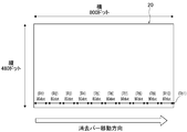
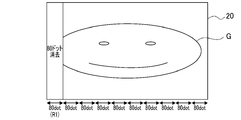
- the erasing operation of the display image on the drawing screen 20 is an operation for moving the erasing bar 40 from the left end to the right end as shown by the arrow in FIG.
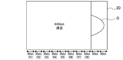
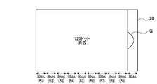
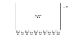
- the drawing screen 20 is spread over the entire vertical region (480 dots) of the region for each of the regions R1 to R10 in units of a predetermined number of pixels in the horizontal direction (80 dots unit in the present embodiment).
- the drawing screen 20 has a width of 800 dots and a height of 480 dots as shown in FIG. 3, but the number of dots on the drawing screen 20 is limited to this. is not.
- the unit of the number of pixels in the regions R1 to R10 to be erased and the number of regions R1 to R10 at the time of the erasing process are not limited to the above 80 dots.
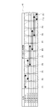
- the erasure bar position detection port 42 is disposed, for example, on the back side of the slide groove 41.
- the six input ports 1 to 6 are connected to the movement direction (left-right direction) of the erasure bar 40. ) Are provided in parallel in a direction orthogonal to.
- the port terminal portions 4a to 4f that are in contact with the terminal portion of the erasing bar 40 correspond to the positions of the regions R1 to R10 having a predetermined number of pixels on the drawing screen 20.
- the left and right directions are arranged differently.
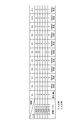
- the contact state between the terminal of the erase bar 40 and each of the port terminal portions 4a to 4f, that is, the input of each of the input ports 1 to 6 is as shown in FIG. 4B. That is, at the position where the erasing bar 40 overlaps the leftmost region R1 of the slide groove 41 (drawing screen 20), only the port terminal portion 4a is in a contact state, and only the input port 1 has an input "1". Is defined as the state P1 of the erase bar position detection port 42. At a position overlapping the area R2 on the right side of the area R1 on the drawing screen 20, the port terminal portions 4a and 4b are in contact with each other, and the input ports 1 and 2 are “1” with input.
- the port terminal portions 4c and 4d are in a contact state, and the input ports 3 and 4 are “1” with input.
- This is defined as a state P6 of the position detection port 42.
- the port terminal portions 4d and 4e are in contact with each other, and the input ports 4 and 5 are “1” with input.
- a state P8 of the position detection port 42 At a position overlapping the region R9 on the right side of the region R9 on the drawing screen 20, only the port terminal portion 4e is in a contact state, and only the input port 5 is “1” with input.
- This state is detected as an erase bar position detection. It is defined as a state P9 of the port 42.
- the port terminal portions 4e and 4f are in contact, and the input ports 5 and 6 are “1” with input. This state is deleted. This is defined as a state P10 of the bar position detection port 42.
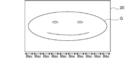
- the erasing bar 40 When erasing the drawing on the drawing screen 20 from the drawing mode shown in FIG. 5A, the erasing bar 40 is slid from the left end (one end) to the right end (the other end) of the slide groove 41 as described above. .
- the control unit 22 displays the drawing screen as shown in FIG. 5B.
- the image in the leftmost region R1 of 20 is deleted including the background.
- the control unit 22 displays the image of the region R1 once erased. , Redisplay and return to the drawing mode.
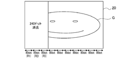
- the control unit 22 displays the drawing screen as shown in FIG. 5C.
- the image of the area (160 dots) including the area R2 is deleted from the 20 areas R1 including the background.
- the storage unit 22a still holds the erased image.
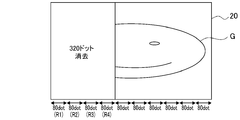
- the control unit 22 performs the regions R1 to R3 (240 dots) of the drawing screen 20 as shown in FIG. 5D. ) Including the background.
- the operation when the erase bar 40 is returned to the left is the same as described above.
- the regions R1 to R8 are sequentially erased in predetermined pixel units (80 dots) as shown in FIGS. 5E, 5F, 5G, 5H, and 5I.
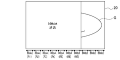
- the control unit 22 leaves the last area R10 (80 dots) on the drawing screen 20 as shown in FIG. Erase.
- the images of the regions R1 to R9 are still held in the storage unit 22a, and when the erase bar 40 is slid leftward, the erased image is displayed again as described above. It is the same.
- the control unit 22 displays the drawing screen 20 as shown in FIG. 5K. Are deleted, and the image information stored in the storage unit 22a is deleted. Therefore, when the erasing bar 40 is moved to the left end of the slide groove 41 (position overlapping the region R1) and the drawing mode is set, all images are erased on the drawing screen 20, and a new drawing is performed. Can do.
- the drawing is stored in the storage unit of the storage unit 22a and erased from the drawing screen 20, By performing a display operation, it is possible to list these images G at a later date, select and redisplay these images G, and then add a drawing.
- the erasing bar arranged at the left end of the slide groove 41 is the same as the erasing operation of a well-known magnet-type drawing apparatus.
- the control unit 22 displays the image (image G) on the drawing screen 20 for each of the regions R1 to R9 having a width of a predetermined pixel unit, as shown in FIGS. 5B to 5J, according to the position of the erasing bar 40.
- Erase When the erasing bar 40 is slid to the right end of the slide groove 41, the images G in all the regions R1 to R10 of the drawing screen 20 are erased as shown in FIG. 5K.
- the image displayed on the drawing screen 20 can be erased by the slide of the well-known erase bar 40, although the drawing screen 20 is a liquid crystal screen. Therefore, even when a small child uses for the first time, the erasing operation can be performed intuitively. Further, in the state before the state P11 in which the erasing bar 40 is moved to the right end of the slide groove 41, the once erased image can be displayed again, which is more convenient than a conventional magnet-type drawing apparatus. .
- the drawing apparatus of the first embodiment is An apparatus main body 10 having a drawing screen 20 composed of a liquid crystal screen; A pressure-sensitive sensor 21 provided on the drawing screen 20 for detecting the pressure applied to the drawing screen 20; An erasing bar 40 provided on the apparatus main body 10 so as to be slidable along the drawing screen 20; An erase bar position detection port 42 as an erase bar position sensor for detecting the position of the erase bar 40; A control unit 22 for executing a drawing process for drawing on the drawing screen 20 along a detection position of the pressure applied to the drawing screen 20; With The control unit 22 is characterized by erasing the image displayed on the drawing screen 20 according to the moving range of the erasing bar 40 when the erasing bar 40 is moved.
- the drawing on the drawing screen 20 can be erased only by performing an operation of sliding the erase bar 40 along the drawing screen 20 which is a conventional common recognition operation and a simple operation. .
- the drawing screen 20 made of a liquid crystal module can be erased by performing an erasing operation based on intuitive or ancient common recognition, and is excellent in usability.
- the drawing apparatus of the first embodiment is When the erasing bar 40 is positioned at one end (left end) of the drawing screen 20, the control unit 22 sets a drawing mode in which drawing can be performed over the entire drawing screen 20, and from the one end (left end) of the erasing bar 40. According to the movement, the image G is erased from one end (left end) of the drawing screen 20. Accordingly, the erasing bar 40 can erase the image G in the entire area of the drawing screen 20 by simply sliding it from one end (left end) to the other end (right end), and performs an operation of tracing and erasing the image as an eraser mode. Compared with, it is excellent in operability.
- the drawing apparatus of Embodiment 1 is The erase bar position detection port 42 as the erase bar position sensor is formed so as to be able to detect an area corresponding to a predetermined pixel unit (80 dots).
- the control unit 22 is characterized by erasing the image G in the area that has passed in accordance with the position of the erasing bar 40. Accordingly, the image G is erased in predetermined pixel units through the erase bar 40, and the position of the erase bar 40 is detected as compared with the case where the erase bar 40 is erased every moment according to the movement of the erase bar 40, and
- the control to erase can be simplified. As a result, the configuration can be simplified and the cost can be reduced.
- the drawing apparatus of Embodiment 1 is
- the control unit 22 includes a storage unit 22a for storing the image G displayed on the drawing screen 20, and before moving to the region R11 of the erasing bar 40, which is an erasing operation for the image G in a predetermined entire area, the erasing bar 40.
- the image G once erased is displayed again by moving in the left direction, which is the movement in the direction opposite to the direction in which the image is erased. Therefore, unlike a conventional magnet-type drawing apparatus, it is possible to cancel erasing in the middle and re-display the image G once erased, which is excellent in usability.
- a new drawing on the drawing screen 20 can be performed by not displaying again, and the switching is an operation based on the movement of the erasure bar 40. It is easy to use compared to what you set.
- the drawing apparatus of Embodiment 1 is
- the erase bar position detection port 42 includes a plurality of ports (input ports 1 to 6) that can come into contact with the terminals of the erase bar 40, and the port terminal portion 4a of each of the input ports 1 to 6 is an area R1 of the drawing screen 20.
- the contact states (P1 to P11) are different from each other. Therefore, the position can be detected with high accuracy by a simple configuration. As a result, the configuration can be simplified and the cost can be reduced.
- the shapes of the apparatus main body and the drawing screen are not limited to the shapes shown in the embodiments. That is, the aspect ratio of the drawing screen, the number of pixels, and the like can be arbitrarily set.
- the erasure bar position sensor is not limited to a structure for detecting based on the lengths of the terminals of the plurality of input ports, as shown in the embodiment. For example, if the erase bar moves along the resistor arranged along the drawing screen and detects the position of the erase bar, such as one that detects the position based on the change in the resistance value, other means can be used. Can do.
- the touch pen is used to input the drawing.
- the present invention is not limited to this, and drawing is performed by pressurizing the drawing screen using something other than the touch pen such as a finger. Also good.
- the position of the erasing bar is arranged on the front side of the drawing screen.
- the position of the erasing bar is not limited to this, and the erasing bar may be provided so as to slide along either the left or right side.
Landscapes
- Engineering & Computer Science (AREA)
- General Engineering & Computer Science (AREA)
- Theoretical Computer Science (AREA)
- Human Computer Interaction (AREA)
- Physics & Mathematics (AREA)
- General Physics & Mathematics (AREA)
- Controls And Circuits For Display Device (AREA)
- Toys (AREA)
Priority Applications (1)
| Application Number | Priority Date | Filing Date | Title |
|---|---|---|---|
| US16/309,032 US10768813B2 (en) | 2016-06-14 | 2017-06-13 | Picture-drawing device |
Applications Claiming Priority (2)
| Application Number | Priority Date | Filing Date | Title |
|---|---|---|---|
| JP2016117921A JP6740020B2 (ja) | 2016-06-14 | 2016-06-14 | お絵描き装置 |
| JP2016-117921 | 2016-06-14 |
Publications (1)
| Publication Number | Publication Date |
|---|---|
| WO2017217421A1 true WO2017217421A1 (ja) | 2017-12-21 |
Family
ID=60664477
Family Applications (1)
| Application Number | Title | Priority Date | Filing Date |
|---|---|---|---|
| PCT/JP2017/021853 Ceased WO2017217421A1 (ja) | 2016-06-14 | 2017-06-13 | お絵描き装置 |
Country Status (3)
| Country | Link |
|---|---|
| US (1) | US10768813B2 (enExample) |
| JP (1) | JP6740020B2 (enExample) |
| WO (1) | WO2017217421A1 (enExample) |
Families Citing this family (6)
| Publication number | Priority date | Publication date | Assignee | Title |
|---|---|---|---|---|
| CN109036122A (zh) * | 2018-08-17 | 2018-12-18 | 张歆 | 一种智能互动虚拟窗 |
| USD930744S1 (en) * | 2019-04-23 | 2021-09-14 | Shenzhen Divoom Technology Co., Ltd. | Children's drawing board |
| DE102020006228A1 (de) * | 2020-10-10 | 2022-04-14 | Hermedia Verlag Gmbh | Löschbares Grafikfeld als Schiefertafelersatzprodukt |
| USD1045875S1 (en) * | 2020-11-27 | 2024-10-08 | Shaogang Cheng | Tablet PC case |
| USD1019724S1 (en) * | 2022-05-24 | 2024-03-26 | Jianhui Li | Protective cover for tablet |
| USD1010659S1 (en) * | 2022-05-24 | 2024-01-09 | Jianhui Li | Protective cover for tablet |
Citations (3)
| Publication number | Priority date | Publication date | Assignee | Title |
|---|---|---|---|---|
| JP3047170U (ja) * | 1997-09-16 | 1998-03-31 | 株式会社タカラ | 幼児用カラーお絵描き玩具 |
| JP2003196024A (ja) * | 2001-12-28 | 2003-07-11 | Tomy Co Ltd | 携帯型お絵描き装置 |
| US20080193909A1 (en) * | 2007-02-12 | 2008-08-14 | Fab/Starpoint | Magnetic drawing apparatus |
Family Cites Families (5)
| Publication number | Priority date | Publication date | Assignee | Title |
|---|---|---|---|---|
| US5401916A (en) * | 1992-09-29 | 1995-03-28 | Ncr Corporation | Method and apparatus for capturing handwritten information and providing visual feedback |
| JP2002229724A (ja) | 2001-02-01 | 2002-08-16 | Jes:Kk | 描画装置 |
| JP3798637B2 (ja) * | 2001-02-21 | 2006-07-19 | インターナショナル・ビジネス・マシーンズ・コーポレーション | タッチパネル式記入媒体装置、その制御方法、及びプログラム |
| WO2005038749A2 (en) * | 2003-10-10 | 2005-04-28 | Leapfrog Enterprises, Inc. | Display apparatus for teaching writing |
| KR102042461B1 (ko) * | 2012-10-31 | 2019-11-08 | 엘지전자 주식회사 | 이동 단말기 및 이동 단말기의 제어 방법 |
-
2016
- 2016-06-14 JP JP2016117921A patent/JP6740020B2/ja not_active Expired - Fee Related
-
2017
- 2017-06-13 US US16/309,032 patent/US10768813B2/en not_active Expired - Fee Related
- 2017-06-13 WO PCT/JP2017/021853 patent/WO2017217421A1/ja not_active Ceased
Patent Citations (3)
| Publication number | Priority date | Publication date | Assignee | Title |
|---|---|---|---|---|
| JP3047170U (ja) * | 1997-09-16 | 1998-03-31 | 株式会社タカラ | 幼児用カラーお絵描き玩具 |
| JP2003196024A (ja) * | 2001-12-28 | 2003-07-11 | Tomy Co Ltd | 携帯型お絵描き装置 |
| US20080193909A1 (en) * | 2007-02-12 | 2008-08-14 | Fab/Starpoint | Magnetic drawing apparatus |
Non-Patent Citations (1)
| Title |
|---|
| E GA UGOKU!? HOZON MO TOKO O DEKIRU!? TAKARA TOMY NO 'SENSEI' (APURI BAN) TTE IMA KOKO MADE SHINKA SHITE IRUNO!?, 15 March 2012 (2012-03-15), Retrieved from the Internet <URL:http://www.tabroid.jp/app/books/2012/03/jp.nas.Sensei.html> [retrieved on 20170821] * |
Also Published As
| Publication number | Publication date |
|---|---|
| US10768813B2 (en) | 2020-09-08 |
| JP6740020B2 (ja) | 2020-08-12 |
| US20190250816A1 (en) | 2019-08-15 |
| JP2017221323A (ja) | 2017-12-21 |
Similar Documents
| Publication | Publication Date | Title |
|---|---|---|
| WO2017217421A1 (ja) | お絵描き装置 | |
| KR101308679B1 (ko) | 터치스크린을 구비한 기기의 특수 기호 입력 장치 및 방법 | |
| JP4686886B2 (ja) | 情報処理装置 | |
| KR102212993B1 (ko) | 묘화 장치 | |
| JP5529616B2 (ja) | 情報処理システム、操作入力装置、情報処理装置、情報処理方法、プログラム及び情報記憶媒体 | |
| US20170010766A1 (en) | Vehicle-mounted information device | |
| US11435870B2 (en) | Input/output controller and input/output control program | |
| JP5265433B2 (ja) | 表示装置、およびプログラム | |
| KR20130005300A (ko) | 정보처리 시스템, 조작입력장치, 정보처리장치, 정보처리방법, 프로그램 및 정보기억매체 | |
| KR20150096826A (ko) | 디스플레이 장치 및 제어 방법 | |
| JP2013012134A (ja) | 手書き入力機能付表示装置 | |
| US20140293349A1 (en) | Image display control apparatus, image display control method, and non-transitory storage medium storing instructions executable by image display control apparatus | |
| JP2021111058A (ja) | 表示装置及び表示制御プログラム | |
| TW200809574A (en) | System, device, method and computer program product for using a mobile camera for controlling a computer | |
| JP4739276B2 (ja) | 表示装置 | |
| US20140258898A1 (en) | User Interface for Drawing with Electronic Devices | |
| US20150015501A1 (en) | Information display apparatus | |
| CN109509240A (zh) | 一种智能设备显示方法、可读存储介质及智能设备 | |
| JP6087602B2 (ja) | 電子黒板 | |
| CN106371644B (zh) | 一种在屏幕上多人同时书写的方法和装置 | |
| JP2013109595A (ja) | 表示システムおよび表示プログラム | |
| JP2004239998A (ja) | ディスプレイ装置 | |
| KR101454534B1 (ko) | 스마트 단말 상의 가상펜을 이용한 드로잉 장치 및 방법 | |
| KR101399662B1 (ko) | 전자칠판의 무한판서 실행 시스템 및 실행 방법 | |
| CN108932054A (zh) | 显示装置、显示方法和非暂时性的记录介质 |
Legal Events
| Date | Code | Title | Description |
|---|---|---|---|
| DPE1 | Request for preliminary examination filed after expiration of 19th month from priority date (pct application filed from 20040101) | ||
| 121 | Ep: the epo has been informed by wipo that ep was designated in this application |
Ref document number: 17813317 Country of ref document: EP Kind code of ref document: A1 |
|
| NENP | Non-entry into the national phase |
Ref country code: DE |
|
| 122 | Ep: pct application non-entry in european phase |
Ref document number: 17813317 Country of ref document: EP Kind code of ref document: A1 |