WO2017217208A1 - コネクタ - Google Patents
コネクタ Download PDFInfo
- Publication number
- WO2017217208A1 WO2017217208A1 PCT/JP2017/019513 JP2017019513W WO2017217208A1 WO 2017217208 A1 WO2017217208 A1 WO 2017217208A1 JP 2017019513 W JP2017019513 W JP 2017019513W WO 2017217208 A1 WO2017217208 A1 WO 2017217208A1
- Authority
- WO
- WIPO (PCT)
- Prior art keywords
- retainer
- housing
- locking position
- terminal
- unit
- Prior art date
Links
Images


Classifications
-
- H—ELECTRICITY
- H01—ELECTRIC ELEMENTS
- H01R—ELECTRICALLY-CONDUCTIVE CONNECTIONS; STRUCTURAL ASSOCIATIONS OF A PLURALITY OF MUTUALLY-INSULATED ELECTRICAL CONNECTING ELEMENTS; COUPLING DEVICES; CURRENT COLLECTORS
- H01R13/00—Details of coupling devices of the kinds covered by groups H01R12/70 or H01R24/00 - H01R33/00
- H01R13/40—Securing contact members in or to a base or case; Insulating of contact members
- H01R13/42—Securing in a demountable manner
-
- H—ELECTRICITY
- H01—ELECTRIC ELEMENTS
- H01R—ELECTRICALLY-CONDUCTIVE CONNECTIONS; STRUCTURAL ASSOCIATIONS OF A PLURALITY OF MUTUALLY-INSULATED ELECTRICAL CONNECTING ELEMENTS; COUPLING DEVICES; CURRENT COLLECTORS
- H01R13/00—Details of coupling devices of the kinds covered by groups H01R12/70 or H01R24/00 - H01R33/00
- H01R13/02—Contact members
- H01R13/20—Pins, blades, or sockets shaped, or provided with separate member, to retain co-operating parts together
-
- H—ELECTRICITY
- H01—ELECTRIC ELEMENTS
- H01R—ELECTRICALLY-CONDUCTIVE CONNECTIONS; STRUCTURAL ASSOCIATIONS OF A PLURALITY OF MUTUALLY-INSULATED ELECTRICAL CONNECTING ELEMENTS; COUPLING DEVICES; CURRENT COLLECTORS
- H01R13/00—Details of coupling devices of the kinds covered by groups H01R12/70 or H01R24/00 - H01R33/00
- H01R13/40—Securing contact members in or to a base or case; Insulating of contact members
- H01R13/42—Securing in a demountable manner
- H01R13/436—Securing a plurality of contact members by one locking piece or operation
- H01R13/4361—Insertion of locking piece perpendicular to direction of contact insertion
- H01R13/4362—Insertion of locking piece perpendicular to direction of contact insertion comprising a temporary and a final locking position
-
- H—ELECTRICITY
- H01—ELECTRIC ELEMENTS
- H01R—ELECTRICALLY-CONDUCTIVE CONNECTIONS; STRUCTURAL ASSOCIATIONS OF A PLURALITY OF MUTUALLY-INSULATED ELECTRICAL CONNECTING ELEMENTS; COUPLING DEVICES; CURRENT COLLECTORS
- H01R13/00—Details of coupling devices of the kinds covered by groups H01R12/70 or H01R24/00 - H01R33/00
- H01R13/46—Bases; Cases
- H01R13/502—Bases; Cases composed of different pieces
- H01R13/506—Bases; Cases composed of different pieces assembled by snap action of the parts
-
- H—ELECTRICITY
- H01—ELECTRIC ELEMENTS
- H01R—ELECTRICALLY-CONDUCTIVE CONNECTIONS; STRUCTURAL ASSOCIATIONS OF A PLURALITY OF MUTUALLY-INSULATED ELECTRICAL CONNECTING ELEMENTS; COUPLING DEVICES; CURRENT COLLECTORS
- H01R13/00—Details of coupling devices of the kinds covered by groups H01R12/70 or H01R24/00 - H01R33/00
- H01R13/46—Bases; Cases
- H01R13/516—Means for holding or embracing insulating body, e.g. casing, hoods
- H01R13/518—Means for holding or embracing insulating body, e.g. casing, hoods for holding or embracing several coupling parts, e.g. frames
-
- H—ELECTRICITY
- H01—ELECTRIC ELEMENTS
- H01R—ELECTRICALLY-CONDUCTIVE CONNECTIONS; STRUCTURAL ASSOCIATIONS OF A PLURALITY OF MUTUALLY-INSULATED ELECTRICAL CONNECTING ELEMENTS; COUPLING DEVICES; CURRENT COLLECTORS
- H01R13/00—Details of coupling devices of the kinds covered by groups H01R12/70 or H01R24/00 - H01R33/00
- H01R13/62—Means for facilitating engagement or disengagement of coupling parts or for holding them in engagement
- H01R13/639—Additional means for holding or locking coupling parts together, after engagement, e.g. separate keylock, retainer strap
-
- H—ELECTRICITY
- H01—ELECTRIC ELEMENTS
- H01R—ELECTRICALLY-CONDUCTIVE CONNECTIONS; STRUCTURAL ASSOCIATIONS OF A PLURALITY OF MUTUALLY-INSULATED ELECTRICAL CONNECTING ELEMENTS; COUPLING DEVICES; CURRENT COLLECTORS
- H01R2201/00—Connectors or connections adapted for particular applications
- H01R2201/26—Connectors or connections adapted for particular applications for vehicles
Definitions
- the present invention relates to a connector.
- Patent Document 1 discloses a connector used for an in-vehicle LAN (local area network).
- a wire harness for in-vehicle LAN is configured by bundling a communication wire that forms a twisted pair wire as a noise countermeasure and a power supply wire for supplying power to a device such as a car navigation system.
- the terminal fittings fixed to these electric wires are inserted into the housing from the rear.
- Patent Document 2 discloses a structure in which a lance that can be elastically bent is formed in the housing and the lance is locked to the terminal fitting.
- a terminal unit is configured by attaching two terminal fittings connected to two communication wires to a terminal holding member having a half structure different from the housing. If the terminal holding member has a halved structure, the terminal fitting can be attached in a direction that intersects the length of the communication wire, eliminating the need to untwist the communication wire and avoiding a reduction in the noise countermeasure function. it can.
- the terminal unit When such a terminal unit is used, as a means for holding the terminal unit against the housing, the terminal unit can be elastically bent with a lance that can be elastically bent, as with the terminal fitting connected to the power supply wire. It is possible to prevent it by action. However, in order to prevent the lance from being pulled out, in addition to a sufficient locking area, a space for bending the lance is required, so that the connector is enlarged in the lance bending direction.
- the present invention has been completed based on the above situation, and aims to reduce the size.
- the present invention A housing; A retainer attached to the housing and displaceable between a temporary locking position and a final locking position; A terminal unit that is attached to the retainer so as to be integrated between the retainer and displaced between a temporary locking position and a final locking position; A terminal holding member constituting the terminal unit; A terminal fitting fixed to an electric wire and attached to the terminal holding member such that a direction in which the electric wire is led out from the terminal holding member intersects with a displacement direction of the retainer; A stopper formed in the housing and facing in a direction opposite to a direction in which the electric wire is led out; When the retainer is in the temporary locking position, the stopper is not locked with the stopper, and the retainer is displaced to the final locking position so that the stopper can be locked. It has a feature in that it has a butting part.
- the terminal unit can be prevented from being pulled out by locking the abutting part to the stopper. Since a lance that can be elastically bent is not used as a means for preventing the terminal unit from being pulled out, it is possible to reduce the size.
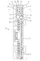
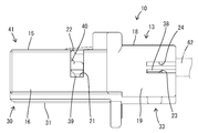
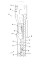
- FIG. 1 The perspective view showing the state which attached the retainer and the terminal unit to the final locking position in the connector of Example 1.
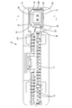
- Retainer perspective view Retainer front view Retainer top view Perspective view of terminal unit Side cross section of terminal unit
- a unit housing portion that houses the terminal unit so as to surround the entire circumference by the housing and the retainer may be formed. According to this configuration, the terminal unit can be protected from foreign matter interference and the like.
- the unit accommodating portion is A housing side cover portion formed in the housing and opened in a displacement direction from the main locking position of the retainer to the temporary locking position;
- the retainer side cover part formed in the retainer so as to be fitted to the housing side cover part and opened in the displacement direction from the temporary locking position of the retainer to the final locking position may be provided. According to this structure, material cost can be reduced compared with the case where a cylindrical part is formed in a housing or a retainer in order to constitute a unit accommodating part.
- the present invention may include an insertion port that is provided in the unit housing portion and allows the terminal unit to be inserted into the unit housing portion. According to this configuration, the terminal unit can be attached to the retainer after the retainer is attached to the housing. Thereby, since the means for holding the terminal unit in the state where the terminal unit is attached to the retainer can be omitted or simplified, the structure of the retainer or the terminal unit can be simplified.
- FIGS. 3, 4, 6, 7, 11, and 13 are defined as the front in the front-rear direction.
- the directions appearing in FIGS. 1 to 10, 12 and 13 are defined as the upper and lower directions as they are.
- the directions appearing in FIGS. 2, 5, 8, and 10 are defined as left and right as they are.
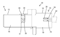
- the connector of the first embodiment includes a synthetic resin housing 10, a synthetic resin retainer 30, and a terminal unit 50.
- the housing 10 as a whole has a flat shape with a large left-right dimension (width dimension) compared to the vertical dimension.
- Most of the left side of the housing 10 is a terminal accommodating portion 11.
- a plurality of terminal accommodating chambers 12 are formed in the terminal accommodating portion 11, and female terminals (not shown) are inserted into the terminal accommodating chambers 12 from the rear of the housing 10.
- Each female terminal is connected to an electric wire (not shown) that is not subjected to noise countermeasures.
- a housing side cover 13 is formed at the right end of the housing 10.
- the housing side cover portion 13 has a function of attaching the retainer 30, a function of accommodating the terminal unit 50, and a function of retaining the terminal unit 50.
- the internal space of the housing side cover 13 is opened downward (moving direction when the retainer 30 is displaced from the final locking position to the temporary locking position), and is also opened both in the front and rear.
- the housing side cover portion 13 includes a left front wall portion 14 that constitutes the right outer surface of the terminal accommodating portion 11, a front upper wall portion 15 that extends horizontally rightward from the upper edge of the right end portion of the terminal accommodating portion 11, and A right front wall 16 extending downward from the right edge of the front upper wall 15.
- the housing side cover portion 13 further includes a left rear wall portion 17 extending rearward from the rear end edge of the left front wall portion 14 and a rear upper wall extending rearward from the rear end edge of the front upper wall portion 15.
- a part 18 and a right rear wall part 19 extending rearward from the rear end edge of the right front wall part 16 are also provided.
- a support rib 20 extending in the front-rear direction is formed at the lower end portion of the inner side surface of the left front wall portion 14.
- a detachment restriction receiving portion 21 facing upward is formed.
- the front upper wall portion 15 is formed with a detection opening 22 in the left-right direction that communicates with the left and right both-side separation restriction receiving portion 21.
- the left rear wall portion 17 and the right rear wall portion 19 are formed with a temporary locking locking hole 23 and a final locking locking hole 24 positioned above the temporary locking locking hole 23.
- a protrusion-like stopper 25 is formed on the inner surface (lower surface) of the front upper wall portion 15 so as to face forward (the direction opposite to the direction in which the electric wires 61 are led out from the terminal holding member 51).
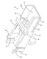
- the retainer 30 includes a horizontal bottom wall portion 31, a left side wall portion 32 ⁇ / b> L that rises upward from the left side edge of the bottom wall portion 31, and a right side that rises upward from the right side edge of the bottom wall portion 31. It is a single part provided with the wall part 32R.
- the bottom wall portion 31, the left side wall portion 32 ⁇ / b> L, and the right side wall portion 32 ⁇ / b> R constitute a retainer side cover portion 33.
- the internal space of the retainer side cover portion 33 is a space for accommodating the terminal unit 50, and the upper side opposite to the housing side cover portion 13 (the movement direction when the retainer 30 is displaced from the temporary lock position to the full lock position) As well as the housing-side cover 13, and is open to both the front and rear.
- a projecting front stop portion 34 facing rearward is formed on the upper surface of the bottom wall portion 31 (inside the retainer side cover portion 33).
- a locking rib 35 extending in the front-rear direction and a locking groove 36 extending in the front-rear direction along the upper edge of the locking rib 35 are formed on the outer surface of the lower end portion of the left side wall portion 32L.
- Each of the rear end portions of the left side wall portion 32L and the right side wall portion 32R is formed in a cantilevered manner upward from its lower end, and is formed with an elastic arm portion 37 that can be elastically displaced in the left-right direction.
- a locking projection 38 is formed on the upper end portion of the outer surface of the elastic arm portion 37.
- a protrusion-shaped detachment restricting portion 39 is formed at the upper end portions of the outer side surfaces of the left side wall portion 32L and the right side wall portion 32R.
- the detachment restricting portion 39 is disposed at a substantially central position in the front-rear direction of the left side wall portion 32L and the right side wall portion 32R.
- the upper end edges of the left side wall part 32L and the right side wall part 32R are connected by a beam part 40 in the left-right direction.
- the beam portion 40 and the separation regulating portion 39 are arranged at the same position in the front-rear direction.
- the retainer 30 is fitted to the housing side cover 13 from below the housing 10 and is selectively attached to the housing 10 at the temporary locking position and the main locking position.
- the retainer side cover portion 33 is accommodated inside the housing side cover portion 13, the left side wall portion 32L overlaps the inner surfaces of the left front wall portion 14 and the left rear wall portion 17, and the right side wall portion 32R is positioned on the right side. It overlaps with the inner surfaces of the front wall portion 16 and the right rear wall portion 19.
- the bottom wall portion 31 closes the lower surface of the internal space of the housing side cover portion 13.
- the housing-side cover 13 and the retainer-side cover 33 constitute a rectangular tube-shaped unit housing 41 having both front and rear surfaces opened.
- the opening at the rear end of the unit accommodating portion 41 serves as an insertion port 42 for accommodating the terminal unit 50 in the unit accommodating portion 41.
- the locking groove 36 is fitted into the support rib 20, and the locking protrusion 38 is locked in the temporary locking locking hole 23 as shown in FIG. Is held in the temporary locking position.
- the detachment restricting portion 39 is locked to the detachment restricting receiving portion 21, whereby the retainer 30 is restricted from detaching downward with respect to the housing 10, and the front-rear direction with respect to the housing 10. Relative displacement is restricted.
- the locking rib 35 is locked so as to be placed on the upper surface of the support rib 20, and as shown in FIGS.
- the retainer 30 is held at the final retaining position.
- the main locking position is a position above the temporary locking position. Therefore, when the retainer 30 is in the temporary locking position, the beam portion 40 is positioned below the detection opening 22, but when the retainer 30 is raised to the main locking position, the beam portion 40 is moved to the detection opening 22. It becomes easy to visually check the presence of the beam portion 40 from the outside of the housing 10.
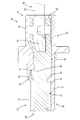
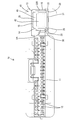
- the terminal unit 50 includes a terminal holding member 51 made of synthetic resin and a pair of terminal fittings 58, and is connected to the front end portion of the twisted pair wire 62. As shown in FIGS. 12 and 13, the terminal unit 50 is elongated in the front-rear direction as a whole, and is inserted into the unit accommodating portion 41 from the rear of the housing 10.
- the terminal holding member 51 is configured by assembling the lower case 52 and the upper case 53 so as to be combined vertically.
- On the lower surface (outer surface) of the lower case 52 an abutting portion 54 facing forward is formed.
- On the upper surface (outer surface) of the upper case 53 a retaining protrusion 55 facing rearward is formed.
- a pair of left and right terminal accommodating spaces 56 are formed inside the terminal holding member 51, and a pair of front and rear terminal retaining portions 57 are formed on the upper surface of each terminal accommodating space 56.
- each terminal accommodating space 56 a terminal fitting 58 is attached.
- the terminal fitting 58 is accommodated in the terminal accommodating space 56 when the lower case 52 and the upper case 53 are combined.
- the terminal fitting 58 is restricted from being detached rearward from the terminal holding member 51 by engaging the pair of front and rear separation restricting protrusions 59 with the terminal retaining portions 57.
- the front end portion of the electric wire 61 is individually connected to the crimping portion 60 at the rear end portion of each terminal fitting 58.
- the electric wire 61 is used as a communication electric wire (signal line), and constitutes a twisted pair wire 62 having a noise reduction function by being twisted spirally.
- a communication electric wire signal line
- two electric wires 61 are collectively surrounded by a sheath 63.
- a front end portion of the sheath 63 is also accommodated in the rear end portion of the terminal accommodating space 56. Therefore, the electric wire 61 (twisted pair wire 62) is led out from the terminal holding member 51 to the rear.
- the direction in which the terminal fitting 58 is attached to the terminal holding member 51 intersects the direction in which the electric wires 61 are led out from the terminal holding member 51 (the length direction of the twisted pair wires 62). It is. Therefore, the dimension for removing the sheath 63 at the front end portion of the twisted pair wire 62 and exposing the electric wire 61 is only a size necessary for crimping the crimping portion 60 of the terminal fitting 58 and the electric wire 61 with a crimping machine (applicator). Good.
- the assembly of the connector is performed according to the following procedure.
- the retainer 30 is attached to the temporary locking position of the housing 10.
- a unit accommodating portion 41 whose rear end opens as an insertion port 42 is formed at the right end portion of the housing 10.
- the terminal unit 50 is inserted into the unit housing portion 41 from the rear of the housing 10.
- the abutting portion 54 of the terminal unit 50 abuts against the front stop portion 34 of the retainer 30, and further insertion operation of the terminal unit 50 is restricted.
- the retaining protrusion 55 is arranged at a position slightly below the stopper 25 and slightly ahead of the stopper 25.
- the terminal unit 50 When the retainer 30 is moved from the temporary locking position to the final locking position, if the terminal unit 50 is displaced rearward from the normal position, the retaining projection 55 contacts the stopper 25 from below. The retainer 30 cannot be moved to the final locking position. Therefore, the terminal unit 50 is not attached to an illegal position with respect to the housing 10 (a position where the terminal fitting 58 is deviated rearward from the normal position). Further, whether or not the retainer 30 has moved to the full locking position can be confirmed by observing whether or not the beam portion 40 of the retainer 30 has advanced into the detection opening 22. When the terminal unit 50 is removed from the housing 10, the terminal unit 50 may be extracted to the rear of the housing 10 by moving the retainer 30 and the terminal unit 50 from the final locking position to the temporary locking position.
- the connector of the present embodiment is attached to the housing 10, the retainer 30 that is attached to the housing 10 and is displaceable between the temporary locking position and the main locking position, and the retainer 30.
- 30 is provided with a terminal unit 50 that is integrated with 30 and is displaced between a temporary locking position and a final locking position.
- the terminal holding member 51 and the terminal fitting 58 constitute a terminal unit 50.
- the terminal fitting 58 is fixed to the front end portion of the electric wire 61, and the terminal holding member 51 is arranged such that the direction (rearward) of the electric wire 61 from the terminal holding member 51 intersects the displacement direction (vertical direction) of the retainer 30. Is attached.
- the stopper 10 is formed in the housing 10 so as to face the direction (front) opposite to the direction in which the electric wires 61 are led out.
- the terminal holding member 51 is not locked with the stopper 25 when the retainer 30 is in the temporary locking position, and the protrusion can be locked to the stopper 25 when the retainer 30 is displaced to the final locking position.
- a contact portion 54 is formed. According to this configuration, when the electric wire 61 is pulled, the abutting portion 54 abuts against the stopper 25, so that the terminal unit 50 is prevented from being detached from the housing 10.
- an elastically bendable lance is not used, so that the connector can be reduced in size (reduced in height). Further, since the abutting portion 54 and the stopper 25 can be shifted from the non-locking state to the locking state without being elastically bent, the reliability of the retaining function is excellent.
- the unit housing portion 41 is formed by the winging and the retainer 30 regardless of the temporary locking position or the final locking position.
- the unit accommodating portion 41 accommodates the terminal unit 50 so as to surround the entire circumference. According to this configuration, if the terminal unit 50 is accommodated in the unit accommodating portion 41, the terminal unit 50 can be protected from foreign matter interference and the like.
- the housing 10 is formed with a housing-side cover portion 13 that is opened in the displacement direction (downward) from the main locking position of the retainer 30 to the temporary locking position.
- a retainer side cover 33 is formed so as to be fitted.
- the retainer side cover portion 33 is opened in the displacement direction from the temporarily locked position of the retainer 30 to the final locked position (that is, the direction opposite to the direction in which the housing side cover portion 13 is opened).
- the unit accommodating portion 41 is formed with an insertion port 42 for allowing the terminal unit 50 to be inserted into the unit accommodating portion 41.
- the present invention is not limited to the embodiments described with reference to the above description and drawings.
- the following embodiments are also included in the technical scope of the present invention.
- (1) when the terminal unit is attached to the retainer, the terminal unit is accommodated in the unit accommodating portion so as to be surrounded over the entire circumference, but the terminal unit is attached to the retainer. Thus, a part of the terminal unit in the circumferential direction may be exposed to the outside.
- both the housing-side cover and the retainer-side cover that constitute the unit housing portion are in a form in which a part in the circumferential direction is opened, but the housing-side cover and the retainer-side cover One or both may be cylindrical.
- the terminal unit is attached to the retainer after the retainer is attached to the housing. However, the terminal unit may be attached to the retainer before the retainer is attached to the housing.
Landscapes
- Connector Housings Or Holding Contact Members (AREA)
- Details Of Connecting Devices For Male And Female Coupling (AREA)
Priority Applications (3)
| Application Number | Priority Date | Filing Date | Title |
|---|---|---|---|
| DE112017003023.4T DE112017003023B4 (de) | 2016-06-15 | 2017-05-25 | Steckverbinder |
| US16/308,888 US10910753B2 (en) | 2016-06-15 | 2017-05-25 | Connector |
| CN201780033531.2A CN109196729B (zh) | 2016-06-15 | 2017-05-25 | 连接器 |
Applications Claiming Priority (2)
| Application Number | Priority Date | Filing Date | Title |
|---|---|---|---|
| JP2016-118636 | 2016-06-15 | ||
| JP2016118636A JP6670446B2 (ja) | 2016-06-15 | 2016-06-15 | コネクタ |
Publications (2)
| Publication Number | Publication Date |
|---|---|
| WO2017217208A1 true WO2017217208A1 (ja) | 2017-12-21 |
| WO2017217208A9 WO2017217208A9 (ja) | 2018-07-26 |
Family
ID=60663607
Family Applications (1)
| Application Number | Title | Priority Date | Filing Date |
|---|---|---|---|
| PCT/JP2017/019513 WO2017217208A1 (ja) | 2016-06-15 | 2017-05-25 | コネクタ |
Country Status (5)
| Country | Link |
|---|---|
| US (1) | US10910753B2 (de) |
| JP (1) | JP6670446B2 (de) |
| CN (1) | CN109196729B (de) |
| DE (1) | DE112017003023B4 (de) |
| WO (1) | WO2017217208A1 (de) |
Families Citing this family (2)
| Publication number | Priority date | Publication date | Assignee | Title |
|---|---|---|---|---|
| JP6988446B2 (ja) * | 2017-12-21 | 2022-01-05 | 株式会社オートネットワーク技術研究所 | コネクタ |
| JP7476752B2 (ja) | 2020-10-02 | 2024-05-01 | 住友電装株式会社 | コネクタ |
Citations (4)
| Publication number | Priority date | Publication date | Assignee | Title |
|---|---|---|---|---|
| JPH04129483U (ja) * | 1991-05-17 | 1992-11-26 | 日本航空電子工業株式会社 | ツイストペア線用コネクタ |
| JPH1064613A (ja) * | 1996-08-19 | 1998-03-06 | Sumitomo Wiring Syst Ltd | コネクタ |
| JP2008153066A (ja) * | 2006-12-18 | 2008-07-03 | Auto Network Gijutsu Kenkyusho:Kk | 分岐コネクタおよび分岐コネクタに接続されるコネクタ |
| JP5598849B2 (ja) * | 2010-08-05 | 2014-10-01 | 古河電気工業株式会社 | コネクタ、コネクタハウジング、およびコネクタの製造方法 |
Family Cites Families (22)
| Publication number | Priority date | Publication date | Assignee | Title |
|---|---|---|---|---|
| JPH0759057B2 (ja) | 1990-09-20 | 1995-06-21 | 三菱電機株式会社 | テレビジョン受信機 |
| US5522740A (en) * | 1994-09-29 | 1996-06-04 | Molex Incorporated | Electrical connector with terminal position assurance device that facilitates fully inserting a terminal |
| CN1187699A (zh) * | 1996-04-24 | 1998-07-15 | 住友电装株式会社 | 连接器 |
| JP3123437B2 (ja) * | 1996-07-31 | 2001-01-09 | 住友電装株式会社 | コネクタ |
| JP3806924B2 (ja) * | 2001-11-22 | 2006-08-09 | 住友電装株式会社 | コネクタ |
| EP1378968B1 (de) * | 2002-07-04 | 2007-11-07 | Sumitomo Wiring Systems, Ltd. | Verbinder |
| JP2004055470A (ja) | 2002-07-23 | 2004-02-19 | Auto Network Gijutsu Kenkyusho:Kk | コネクタ |
| JP2007280850A (ja) * | 2006-04-10 | 2007-10-25 | Sumitomo Wiring Syst Ltd | 端子金具 |
| DE102009052772B4 (de) * | 2008-12-01 | 2014-02-13 | Sumitomo Wiring Systems, Ltd. | Ein Verbinder |
| JP2012079552A (ja) * | 2010-10-01 | 2012-04-19 | Sumitomo Wiring Syst Ltd | コネクタ |
| JP2012216343A (ja) * | 2011-03-31 | 2012-11-08 | Sumitomo Wiring Syst Ltd | コネクタ |
| JP5772468B2 (ja) * | 2011-10-06 | 2015-09-02 | 住友電装株式会社 | コネクタ |
| JP5754412B2 (ja) * | 2012-04-26 | 2015-07-29 | 住友電装株式会社 | コネクタ |
| JP5846083B2 (ja) * | 2012-09-06 | 2016-01-20 | 住友電装株式会社 | コネクタ |
| JP6124134B2 (ja) * | 2013-07-26 | 2017-05-10 | 住友電装株式会社 | コネクタ |
| JP6124133B2 (ja) * | 2013-07-26 | 2017-05-10 | 住友電装株式会社 | コネクタ |
| JP6040911B2 (ja) * | 2013-10-31 | 2016-12-07 | 住友電装株式会社 | コネクタ |
| JP6015628B2 (ja) * | 2013-10-31 | 2016-10-26 | 住友電装株式会社 | コネクタ |
| JP6292468B2 (ja) * | 2014-01-31 | 2018-03-14 | 住友電装株式会社 | コネクタ |
| JP6195165B2 (ja) * | 2014-03-13 | 2017-09-13 | 住友電装株式会社 | コネクタ |
| JP6311396B2 (ja) * | 2014-03-28 | 2018-04-18 | 住友電装株式会社 | コネクタ |
| JP2016025045A (ja) | 2014-07-24 | 2016-02-08 | 矢崎総業株式会社 | コネクタと端子金具の接続構造 |
-
2016
- 2016-06-15 JP JP2016118636A patent/JP6670446B2/ja active Active
-
2017
- 2017-05-25 WO PCT/JP2017/019513 patent/WO2017217208A1/ja active Application Filing
- 2017-05-25 CN CN201780033531.2A patent/CN109196729B/zh active Active
- 2017-05-25 US US16/308,888 patent/US10910753B2/en active Active
- 2017-05-25 DE DE112017003023.4T patent/DE112017003023B4/de active Active
Patent Citations (4)
| Publication number | Priority date | Publication date | Assignee | Title |
|---|---|---|---|---|
| JPH04129483U (ja) * | 1991-05-17 | 1992-11-26 | 日本航空電子工業株式会社 | ツイストペア線用コネクタ |
| JPH1064613A (ja) * | 1996-08-19 | 1998-03-06 | Sumitomo Wiring Syst Ltd | コネクタ |
| JP2008153066A (ja) * | 2006-12-18 | 2008-07-03 | Auto Network Gijutsu Kenkyusho:Kk | 分岐コネクタおよび分岐コネクタに接続されるコネクタ |
| JP5598849B2 (ja) * | 2010-08-05 | 2014-10-01 | 古河電気工業株式会社 | コネクタ、コネクタハウジング、およびコネクタの製造方法 |
Also Published As
| Publication number | Publication date |
|---|---|
| CN109196729A (zh) | 2019-01-11 |
| US20200313334A1 (en) | 2020-10-01 |
| WO2017217208A9 (ja) | 2018-07-26 |
| JP2017224473A (ja) | 2017-12-21 |
| US10910753B2 (en) | 2021-02-02 |
| CN109196729B (zh) | 2020-07-17 |
| DE112017003023T5 (de) | 2019-03-14 |
| DE112017003023B4 (de) | 2024-05-23 |
| JP6670446B2 (ja) | 2020-03-25 |
Similar Documents
| Publication | Publication Date | Title |
|---|---|---|
| EP1764879B1 (de) | Verbinder, Verbinderanordnung und Montageverfahren | |
| JP4949936B2 (ja) | コネクタ | |
| KR101527057B1 (ko) | 전기 콘택 요소와 케이블에 대한 고정을 갖는 플러그 커넥터 하우징 | |
| WO2018163788A1 (ja) | シールド端子及びシールドコネクタ | |
| WO2012086145A1 (en) | Connector housing | |
| JP4958684B2 (ja) | コネクタ | |
| JP6769353B2 (ja) | 端子ユニット及びコネクタ | |
| JP2009541919A (ja) | 電気コネクタ | |
| WO2018168368A1 (ja) | 端子ユニット及びコネクタ | |
| US10971851B2 (en) | Miniaturized connector with a terminal holding member | |
| JP2006324227A (ja) | コネクタ | |
| JP6667107B2 (ja) | コネクタ | |
| KR20130124568A (ko) | 커넥터 | |
| JP6665700B2 (ja) | コネクタ | |
| JP5093088B2 (ja) | 防水コネクタ | |
| EP1662618B1 (de) | Gehäuse eines elektrischen Verbinder, ein elektrischer Verbinder und eine Verbinderanordnung | |
| WO2017217208A1 (ja) | コネクタ | |
| JP2007059153A (ja) | コネクタ | |
| JP4544065B2 (ja) | コネクタ | |
| JP2017073301A (ja) | コネクタ | |
| JP2007026764A (ja) | 防水コネクタ | |
| JP5104639B2 (ja) | コネクタ | |
| JP2005183342A (ja) | コネクタ | |
| CN107453073B (zh) | 具有插入限制器的盒式端子 | |
| JP6175417B2 (ja) | コネクタ |
Legal Events
| Date | Code | Title | Description |
|---|---|---|---|
| 121 | Ep: the epo has been informed by wipo that ep was designated in this application |
Ref document number: 17813110 Country of ref document: EP Kind code of ref document: A1 |
|
| 122 | Ep: pct application non-entry in european phase |
Ref document number: 17813110 Country of ref document: EP Kind code of ref document: A1 |