EP1378968B1 - Verbinder - Google Patents
Verbinder Download PDFInfo
- Publication number
- EP1378968B1 EP1378968B1 EP02019160A EP02019160A EP1378968B1 EP 1378968 B1 EP1378968 B1 EP 1378968B1 EP 02019160 A EP02019160 A EP 02019160A EP 02019160 A EP02019160 A EP 02019160A EP 1378968 B1 EP1378968 B1 EP 1378968B1
- Authority
- EP
- European Patent Office
- Prior art keywords
- locking
- terminal fitting
- locking surface
- locking portion
- female terminal
- Prior art date
- Legal status (The legal status is an assumption and is not a legal conclusion. Google has not performed a legal analysis and makes no representation as to the accuracy of the status listed.)
- Expired - Lifetime
Links
Images


Classifications
-
- H—ELECTRICITY
- H01—ELECTRIC ELEMENTS
- H01R—ELECTRICALLY-CONDUCTIVE CONNECTIONS; STRUCTURAL ASSOCIATIONS OF A PLURALITY OF MUTUALLY-INSULATED ELECTRICAL CONNECTING ELEMENTS; COUPLING DEVICES; CURRENT COLLECTORS
- H01R13/00—Details of coupling devices of the kinds covered by groups H01R12/70 or H01R24/00 - H01R33/00
- H01R13/40—Securing contact members in or to a base or case; Insulating of contact members
- H01R13/42—Securing in a demountable manner
- H01R13/422—Securing in resilient one-piece base or case, e.g. by friction; One-piece base or case formed with resilient locking means
- H01R13/4223—Securing in resilient one-piece base or case, e.g. by friction; One-piece base or case formed with resilient locking means comprising integral flexible contact retaining fingers
-
- H—ELECTRICITY
- H01—ELECTRIC ELEMENTS
- H01R—ELECTRICALLY-CONDUCTIVE CONNECTIONS; STRUCTURAL ASSOCIATIONS OF A PLURALITY OF MUTUALLY-INSULATED ELECTRICAL CONNECTING ELEMENTS; COUPLING DEVICES; CURRENT COLLECTORS
- H01R13/00—Details of coupling devices of the kinds covered by groups H01R12/70 or H01R24/00 - H01R33/00
- H01R13/02—Contact members
- H01R13/10—Sockets for co-operation with pins or blades
- H01R13/11—Resilient sockets
- H01R13/111—Resilient sockets co-operating with pins having a circular transverse section
-
- H—ELECTRICITY
- H01—ELECTRIC ELEMENTS
- H01R—ELECTRICALLY-CONDUCTIVE CONNECTIONS; STRUCTURAL ASSOCIATIONS OF A PLURALITY OF MUTUALLY-INSULATED ELECTRICAL CONNECTING ELEMENTS; COUPLING DEVICES; CURRENT COLLECTORS
- H01R13/00—Details of coupling devices of the kinds covered by groups H01R12/70 or H01R24/00 - H01R33/00
- H01R13/02—Contact members
- H01R13/10—Sockets for co-operation with pins or blades
- H01R13/11—Resilient sockets
- H01R13/114—Resilient sockets co-operating with pins or blades having a square transverse section
-
- H—ELECTRICITY
- H01—ELECTRIC ELEMENTS
- H01R—ELECTRICALLY-CONDUCTIVE CONNECTIONS; STRUCTURAL ASSOCIATIONS OF A PLURALITY OF MUTUALLY-INSULATED ELECTRICAL CONNECTING ELEMENTS; COUPLING DEVICES; CURRENT COLLECTORS
- H01R13/00—Details of coupling devices of the kinds covered by groups H01R12/70 or H01R24/00 - H01R33/00
- H01R13/40—Securing contact members in or to a base or case; Insulating of contact members
- H01R13/42—Securing in a demountable manner
- H01R13/436—Securing a plurality of contact members by one locking piece or operation
- H01R13/4361—Insertion of locking piece perpendicular to direction of contact insertion
- H01R13/4362—Insertion of locking piece perpendicular to direction of contact insertion comprising a temporary and a final locking position
Definitions
- the present invention relates to a connector.
- a connector in which a terminal fitting is locked by a locking portion provided in a connector housing is known from Japanese Unexamined Patent Publication No. 4-115475 .
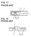
- a cavity 3 into which a terminal fitting 2 is insertable from behind is provided and a locking portion 4 resiliently engageable with the inserted terminal fitting 2 to lock it is provided at the bottom surface of the cavity 3 as shown in FIG. 17.
- This locking portion 4 is comprised of an arm 4a resiliently deformable along vertical direction and a fastening projection 4b projecting from the upper surface of the arm 4a and fittable into a holding hole 2a formed in the bottom wall of the terminal fitting 2 to engage the edge of the hole 2a.
- the locking portion 4 tends to lack strength and may be resiliently deformed with force to be disengaged if an excessive pulling force acts on the terminal fitting 2 in its locked state.
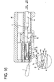
- it can be considered to incline a locking surface 5 of the fastening projection 4b engageable with the terminal fitting 2 at an obtuse angle to a withdrawing direction as shown in FIG. 18. Then, even if a force acts to pull the terminal fitting 2 backward in the locked state, a component of force acts on the locking portion 4 in a direction opposite from the deforming direction by the inclination of the locking surface 5, making it difficult to disengage the locking portion 4. Therefore, a force to lock the terminal fitting 2 can be increased.
- the locking surface 5 is inclined as above, the following problem comes up at the time of detaching the terminal fitting 2. Specifically, the terminal fitting 2 is detached by being withdrawn while forcibly resiliently deforming the locking portion 4 by a disengagement jig. However, since the locking surface 5 is inclined forward toward its upper end (rear end with respect to the deforming direction) and a trace of displacement of the locking surface 5 during the resilient deformation is located more forward than that of FIG. 17, the locking surface 5 is more likely to interfere with the edge of the locking hole 2a when the locking portion 4 is resiliently deformed. Thus, operability has not been satisfactory.
- EP-A-1 073 154 discloses a connector having a slot formed in the housing to accommodate a terminal and a lance disposed in the slot to engage with and latch the terminal inserted into a slot.
- the lance has a tip shape with a chamfer which is formed at an inside corner of the tip.
- EP-A-1 209 766 discloses a connector having terminal housing chamber with a pair of flexible arms supported by both the circumferential wall and the front wall of the connector housing, and an engagement member supported at both sides by the flexible arms.
- the terminal upon insertion through the openings engages with the engagement member, being prevented from being put out.
- the engagement member has a lower oblique surface and a front portion which is an engagement surface substantially intersecting the terminal inserting direction.
- US-B2-6 341 985 discloses a connector unit, wherein the metal terminal is being locked by a lance for prevention of backward withdrawal and wherein there is provided at least one draw jig hole adjacent to the terminal insertion hole, said draw jig hole being provided with a guide support section which can guide a draw jig to move back and forth and bear a reaction force from the lance acting on a draw jig when the lance is disengaged.
- the object of the present invention was completed based on the above problem and an object thereof is to improve a detaching operability of a terminal fitting while in particular allowing to secure a sufficient force to lock the terminal fitting.
- a connector in which, when at least one terminal fitting is at least partly inserted into a respective cavity provided in a connector housing, a locking portion supported at both ends provided in the cavity is at least partly restored to resiliently engage and lock the terminal fitting after being resiliently deformed in a deforming direction intersecting with inserting and withdrawing directions of the terminal fitting, wherein a locking surface of the locking portion engageable with the terminal fitting comprises a deforming-direction front section (or section of the locking surface being arranged at the front or forward side as seen in the deforming direction of the locking portion) and a deforming-direction rear section (or section of the locking surface being arranged at the back or rearward side as seen in the deforming direction of the locking portion), and, whereas an angle of the deforming-direction rear section to the withdrawing direction of the terminal fitting is set smaller than an angle of the deforming-direction front section to the withdrawing direction of the terminal fitting.
- the terminal fitting is or can be pulled backward while the locking portion is forcibly resiliently deformed to be disengaged from the terminal fitting.
- the angle of the deforming-direction rear section to the withdrawing direction is set smaller than the angle of the deforming-direction front section thereto, a trace of displacement of the locking surface during the resilient deformation of the locking portion can be located more backward as compared to a case where the locking surface has the same angle of inclination over the entire length.
- the locking portion is more unlikely to interfere with the terminal fitting when being resiliently deformed, making a detaching operability of the terminal fitting satisfactory.
- the angle of the deforming-direction front section is inclined at an obtuse angle (or angle greater than 90° and smaller than 180°) to the withdrawing direction of the terminal fitting.
- the terminal fitting at least partly inserted into the cavity of the connector housing is so held as not to come out by the resilient engagement of the locking portion.
- the deforming-direction front section of the locking surface of the locking portion is inclined at an obtuse angle to the withdrawing direction of the terminal fitting, even if a force acts to pull the terminal fitting backward in its locked state, a component of force acts on the locking portion in a direction opposite from the deforming direction, making it difficult to disengage the locking portion. Therefore, a force to lock the terminal fitting can be increased.
- a connector in which, when a terminal fitting is inserted into a cavity provided in a connector housing from behind, a locking portion provided in or at the cavity is restored to resiliently engage and lock the terminal fitting after being resiliently deformed in a direction intersecting with inserting and withdrawing directions of the terminal fitting, wherein a locking surface of the locking portion engageable with the terminal fitting comprises a deforming-direction front section (or section of the locking surface being arranged at the front as seen in the deforming direction of the locking portion) and a deforming-direction rear section (or section of the locking surface being arranged at the back as seen in the deforming direction of the locking portion), and an angle of the deforming-direction front section is inclined at an obtuse angle to the withdrawing direction of the terminal fitting, whereas an angle of the deforming-direction rear section to the withdrawing direction is set smaller than the angle of the deforming-direction front section.
- the terminal fitting inserted into the cavity of the connector housing is so held as not to come out by the resilient engagement of the locking portion.
- the deforming-direction front section of the locking surface of the locking portion is inclined at an obtuse angle to the withdrawing direction of the terminal fitting, even if a force acts to pull the terminal fitting backward in its locked state, a component of force acts on the locking portion in a direction opposite from the deforming direction, making it difficult to disengage the locking portion. Therefore, a force to lock the terminal fitting can be increased.
- the terminal fitting is pulled backward while the locking portion is forcibly resiliently deformed to be disengaged from the terminal fitting.
- the angle of the deforming-direction rear section to the withdrawing direction is set smaller than the angle of the deforming-direction front section thereto, a trace of displacement of the locking surface during the resilient deformation of the locking portion can be located more backward as compared to a case where the locking surface has the same angle of inclination over the entire length.
- the locking portion is more unlikely to interfere with the terminal fitting when being resiliently deformed, making a detaching operability of the terminal fitting satisfactory.
- the angle of the deforming-direction rear section is arranged substantially normal to the inserting and withdrawing directions of the terminal fitting.
- the terminal fitting comprises a locking projection projecting therefrom which is engageable with the deforming-direction front section of the locking surface for locking.
- the deforming-direction front section is inclined substantially in the same direction as a locking section of the terminal fitting.
- the locking portion is supported at both ends.
- the locking portion is supported at both ends, a high strength can be maintained even if the thickness is reduced as compared to conventional locking portions supported only at one end and, accordingly, a force to lock the terminal fitting can be enhanced.
- the connector suited to being miniaturized can be provided.
- the connector housing is formed with an opening which is open forward and left upon forming the locking surface of the locking portion, and wherein a section of the locking portion projecting more forward than the locking surface is connected with at least one side surface of the opening.
- the section of the locking portion projecting more forward than the locking surface is connected with the at least one side surface of the opening, this connected section does not hinder the formation of the locking surface, enabling the locking surface to be formed wider.
- the connector is miniaturized, a sufficient locking force can be secured for the terminal fitting.
- the connector suited to being miniaturized can be provided.
- the section of the locking portion projecting more forward than the locking surface is formed with a maneuverable groove which is substantially open forward and is maneuverable by a disengagement jig to forcibly resiliently deform the locking portion.
- the disengagement jig can be inserted into the opening for maneuvering the maneuverable groove.
- jig-introducing groove forks the section of the locking portion projecting more forward than the locking surface.
- FIGS. 1 to 16 One preferred embodiment of the present invention is described with reference to FIGS. 1 to 16.
- a female connector in which one or more female terminal fittings 10 are at least partly inserted in a female connector housing 40 (hereinafter, merely “female housing 40"). While being at least partly accommodated in the female housing 40, the female terminal fittings 10 are electrically connectable with male terminal fittings at least partly accommodated in a mating male housing (neither male terminal fittings nor male housing is shown) to be connected with the female housing 40.
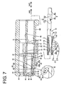
- directions IWD of inserting and withdrawing the female terminal fittings 10 into and from the female housing 40 are referred to as a forward direction and a backward direction, respectvely, and reference is made to FIG. 7 concerning vertical direction.
- the female terminal fitting 10 is formed into a desired shape by, for example, embossing, folding and/or bending a metallic base material stamped or cut out into a specified (predetermined or predeterminable) shape.
- This female terminal fitting 10 is, as shown in FIGS. 4 and 5, roughly constructed such that a main portion 11 substantially in the form of a box having open front and rear ends and a barrel portion 12 to be crimped or bent or folded into connection with an end of a wire W are connected one after the other.
- the barrel portion 12 is comprised of two front and rear pairs of crimping pieces 12a, 12b, wherein the front pair of crimping pieces 12a are or can be crimped or bent or folded into connection with a core Wa of the wire W, and the rear pair of crimping pieces 12b are or can be crimped or bent or folded into connection with an insulated portion Wb of the wire W.
- the main portion 11 is comprised of a ceiling wall 13 extending in forward and backward or longitudinal directions, a pair of side walls 14, 15 extending down from the opposite lateral edges or edge portions of the ceiling wall 13, a bottom wall 16 projecting from the projecting end of the left side wall 14 of FIG. 4 to substantially face the ceiling wall 13, and an outer wall 17 projecting from the projecting end or edge portion of the right side wall 14 of FIG. 4 to be at least partly placed below or outside of the bottom wall 16.
- the front end of the ceiling wall 13 is located at a position retracted backward as compared to those of the other walls 14, 15, 16 and 17, and a resilient contact piece 18 projects from this front end as shown in FIG 7.
- the resilient contact piece 18 preferably is supported only at one end and has a substantially triangular or bent or pointed shape by folding a tongue piece projecting forward from the front end of the ceiling wall 13.
- the resilient contact piece 18 can be resiliently brought into contact with a tab of a mating male terminal fitting at least partly inserted into the main portion 11 from front.
- a receiving portion 19 projects inward from the bottom wall 16 substantially facing or corresponding to the resilient contact piece 18.
- the receiving portion 19 can hold the tab while squeezing it in cooperation with the resilient contact piece 18 (or the tab can be arranged between the receiving portion 19 and the resilient contact piece 18). Further, a portion of the ceiling wall 13 is embossed to project inward, thereby forming an excessive deformation preventing projection or portion 20 for preventing an excessive resilient deformation of the resilient contact piece 18 by being engaged or engageable with the resilient contact piece 18 before the resilient contact piece 18 is resiliently deformed beyond its resiliency limit.
- the outer wall 17 is divided into a front portion 17a and a rear portion 17b by a cut-away portion 21 preferably formed over the substantially entire width substantially substantially at its longitudinal middle portion.
- the lock portion 13 can at least partly enter this cut-away portion 21 and can be engaged with a front cut end surface 21 a of the cut-away portion 21.
- the front cut end surface 21 a of the cut-away portion 21 which surface serves as a locking surface engageable with the locking portion 43 is inclined inwardly or upward to the back preferably over its substantially entire area. In other words, the front cut end surface 21a overhangs or is back-tapered or is undercut.
- This cut-away portion 21 has a length slightly shorter than half the length of the outer wall 17 and extends up to the bottom end of the side wall 15 at the upper side in FIG. 5.
- a bulging piece 22 projecting from the projecting end of the bottom wall 16 is brought or bringable into contact with the bottom end surface (cut end surface of the cut-away portion 21 at the side) of this side wall 15 to hold the bottom wall 16 substantially horizontally.
- a recess 23 is so formed as to be slightly lower than a rear half portion thereof preferably over an substantially entire area except a contact portion of the bulging piece 22 with the side wall 15, thereby increasing a depth of engagement with the locking portion 43.
- the front portion 17a of the outer wall 17 is slightly shorter than the rear portion 17b in forward and backward or longitudinal directions.
- a rear-portion holding piece or portion 24 bent toward the ceiling wall 13 (inward direction) and the stabilizer 25 bent in an opposite direction (outward direction) are provided one after the other at the projecting end of the rear portion 17b of the outer wall 17.
- the rear-portion holding piece 24 holds the rear portion 17b while preventing the rear portion 17b from making loose forward and backward movements (or movements along the longitudinal direction of the terminal fitting 10) by being fitted into a rear-portion holding groove or recess 26 formed in the side wall 14 shown in FIG. 6.
- the stabilizer 25 can guide the insertion of the female terminal fitting 10 by being at least partly inserted along the stabilizer-inserting groove 26 in the cavity 41.
- the front end of the rear-portion holding piece 24 and the front end of the rear portion 17b are substantially aligned with each other, whereas the rear end of the stabilizer 25 and the rear end of the rear portion 17b are substantially aligned with each other.
- a widthwise center portion of the rear end of the rear portion 17b is embossed to project outward, thereby forming a projection 27 preferably having a length substantially equal to that of the stabilizer 25.
- This projection 27 can be brought into contact with the bottom surface of the cavity 41 (upper surface of the projection-inserting groove 47) when the female terminal fitting 10 is inserted into the cavity 41.
- a retainer 52 to be mounted into the female housing 40 is engageable with a stepped portion 28 (rear end surfaces of the bottom wall 16 and the rear portion 17b of the outer wall 17) at the rear bottom end of the main portion 11 including this projection 27.
- the locking projection 29 is, as shown in FIGS. 5 and 6, substantially in the form of a pyramid having a vertex at its front end and is open backward.
- the lokking projection 29 is such that a pyramid portion 29a formed by three or more slanted surfaces and a substantially rectangular or parallelepipedic tube portion 29b preferably substantially having constant width and height and formed by three or more side surfaces are connected one after the other.
- the pyramid portion 29a of the lokking projection 29 is tapered and preferably has its front end slightly rounded, so that the locking projection 29 can be smoothly at least partly inserted along the projection-inserting groove 47 in the process of inserting the female terminal fitting 10 into the cavity 41.
- the rectangular tube portion 29b of the locking projection 29 is formed to overhang backward or to be undercut or back-tapered preferably substantially along the inclination of the front cut end surface 21a of the cut-away portion 21 and projects more backward than the front portion 17a of the outer wall 17.
- This locking projection 29 projects up to the substantially same height as the projection 27, and is at least partly insertable into the projection-inserting groove 47 of the cavity 41 similar to the projection 27.
- the rear edge of the locking projection 29 serving as a locking surface engageable with the locking portion 43 is formed by the front cut end surface 21a of the cut-away portion 21 and is inclined inwardly or upward to the back.
- the rear end surfaces of the portions of the front portion 17a of the outer wall 17 at the opposite sides of the locking projection 29 are also formed by the front cut end surface 21 a of the cut-away portion 21 inclined inwardly or upward to the back or toward the cut-away portion 21 and is engageable with the locking portion 43 (see FIGS. 8 and 12).
- a front-portion holding piece or portion 30 bent toward the ceiling wall 33 is provided at the projecting end or end portion (end to be brought substantially into abutment against the side wall 14) of the front portion 17a of the outer wall 17.
- the front-portion holding piece 10 holds the front portion 17a while preventing the front portion 17a from making loose forward and backward or longitudinal movements by being fitted into a front-portion holding groove or recess 31 formed in the side wall 14 as shown in FIG. 6.
- This front-portion holding piece 30 projects more backward than the front portion 17a of the outer wall 17.
- the cut-away portion 21 extends into the base end of the front-portion holding piece 30, and the cut end surface 21a thereof is inclined inwardly or upward to the back as already described. A side end of the locking portion 43 is engageable with this cut end surface 21a.
- the female housing 40 is molded e.g. of a synthetic resin, and a plurality of cavities 41 into which the female terminal fittings 10 are at least partly insertable preferably from behind are arranged substantially side by side along widthwise direction at one or more, e.g. two stages as shown in FIGS. 1, 2 and 7.
- the female terminal fitting 10 at least partly inserted into the cavity 41 can be resiliently locked by the locking portion 43 (to be described in detail later) provided at a bottom or lateral wall 42 of the cavity 41, and is preferably supported at its front limit position by a front wall 44 of the female housing 40.
- the front wall 44 of the female housing 40 is formed with tab insertion holes 45 for permitting the tabs of the mating male terminal fittings to be at least partly inserted into the cavities 41 preferably from front, and conical or tapered or converging guide surfaces 46 are formed at the front edges of the tab insertion holes 45 preferably over the substantially entire circumference, so that the insertion of the tabs can be smoothly guided.
- the projection-inserting groove 47 along which the locking projection 29 and the projection 27 of the female terminal fitting 10 are at least partly insertable and the stabilizer-inserting groove 48 along which the stabilizer 25 is at least partly insertable are so formed in the bottom wall 42 of the cavity 41 as to have open rear ends or ends towards the inserting side.
- the projection-inserting groove 47 is formed substantially in the widthwise center of the cavity 41, whereas the stabilizer-inserting groove 48 is formed at the right side of the projection-inserting groove 47 in FIG. 2.
- the projection-inserting groove 47 is formed to be substantially continuous with the locking portion 43 as described below, whereas the front end position of the stabilizer-inserting groove 48 is set at a position slightly behind the locking portion 43.
- a jutting or projecting portion 49 gradually jutting or projecting out inwardly (toward the locking portion 43) preferably over the substantially entire width is provided at the front end of the upper surface (surface facing the locking portion 43) of the cavity 41.
- the front end of the female terminal fitting 10 at least partly inserted into the cavity 41 is pushed toward the locking portion 43 by this jutting portion 49 to increase a depth of engagement with the locking portion 43.
- the peripheral edge of the rear end of the cavity 41 is inclined inwardly to the front substantially over the entire circumference except only a part so as to guide the female terminal fitting 10.
- a restricting portion 50 which is an end surface extending in a direction at an angle different from 0° or 180°, preferably substantially normal to the inserting and withdrawing directions IWD of the female terminal fitting 10 is provided at an upper-left position of the peripheral edge of the rear end of the cavity 41 in FIG. 2.
- This restricting portion 50 is brought or bringable into contact with the stabilizer 25 when the female terminal fitting 10 is improperly inserted upside down into the cavity 41, thereby hindering the insertion of the stabilizer 25.
- the substantially front half of the cavity 41 is narrower than the substantially rear half thereof as shown in FIG. 9.
- This retainer mount hole 51 is formed at such a position as to laterally expose longitudinal middle portions (portions slightly behind the locking portions 43) of the respective cavities 41 e.g. to outside below.
- the retainer 52 includes fastening portions 53 arrayed at one or more, e.g. two stages so as to substantially correspond to the respective cavities 41, and is vertically movable between two positions in the female housing 40: a partial locking or first position (see FIG. 7) where the respective fastening portions 53 are retracted laterally, e.g.
- This retainer 52 can be selectively held at the partial locking position and the full locking position by an unillustrated holding means. The retainer 52 is not shown in FIGS. 9 and 13.
- the locking portion 43 is provided at the front part (part before or near or adjacent the retainer mount hole 51) of the bottom wall 42 of the cavity 41 and has an arm 54 supported at both front and rear ends.
- a fastening projection 55 which can at least partly enter the cut-away portion 21 of the female terminal fitting 10 to engage the front cut end surface 21 a at least partly projects into the cavity 41 from the upper surface of the arm 54.
- the locking portion 43 preferably is substantially transversely symmetrical when viewed from front.
- the arm 54 has its opposite bottom ends chamfered or beveled in a laterally long or elongated rectangular front view (see FIG. 1) and has a width substantially equal to that of the cavity 41 (precisely speaking, slightly smaller than the width of the cavity 41) (see FIG. 9).
- the arm 54 is resiliently deformable in a deformation direction DD, preferably substantially along vertical direction (direction DD intersecting with the inserting and withdrawing directions IWD of the female terminal fitting 10) with the front and rear supported portions as supporting points and is in a substantially arch or bridge-like shape in which a longitudinal middle portion thereof is located at a bottommost position (see FIG. 10) during the deformation.
- a deformation permitting space for permitting the resilient deformation of the arm 54 is so provided in the deformation direction DD, e.g. below the arm 54, as to have a specified height.
- a pair of excessive deformation preventing rail portions 56 preferably having a substantially triangular cross section are provided along the longitudinal direction of the locking portion 43. The excessive deformation preventing rail portions 56 can prevent an excessive resilient deformation of the locking portion 43 by substantially engaging the locking portion 43 before the locking portion 43 is resiliently deformed beyond its resiliency limit or damaged.
- a rear portion 54b of the arm 54 is connected with the bottom wall 42 preferably over the substantially entire width and sloped upward toward the front, whereas a front portion 54a thereof is partly connected with the front wall 44 of the female housing 40 and is substantially horizontal.
- the projection-inserting groove 47 formed in the bottom wall 42 is continuously formed in the rear portion 54b, and parts of the rear portion 54b left at the opposite sides of the projection-inserting groove 47 serve as rear supporting portions 57 for supporting the female terminal fitting 10 laterally or from below.
- the fastening projection 55 preferably has a width equal to the entire width of the arm 54 (see FIG. 9), the front end position thereof is substantially aligned with that of the rear portion 54b of the arm 54, and the rear surface thereof is so inclined as to be continuous with the rear portion 54b.
- the projection-inserting groove 47 formed in the rear portion 54b of the arm 54 is continuously formed in this fastening projection 55.
- the fastening projection 55 is recessed in its widthwise middle portion when viewed from front (see FIG. 1).
- the front surface of the fastening projection 55 serves as an upper locking surface 58 (first locking portion or deforming-direction rear section of the locking surface 64) mainly engageable with portions of the front cut end surface 21 a of the cut-away portion 21 of the female terminal fitting 10 at the opposite sides of the locking projection 29 (see FIG. 12).
- This upper locking surface 58 extends in a direction substantially at an angle different from 0° or 180°, preferably substantially normal to forward and backward or longitudinal directions (inserting and withdrawing directions IWD of the female terminal fitting 10).
- a maneuverable groove 59 which is open forward and into which a disengagement jig J (see FIG.
- the front portion 54a of the arm 54 is made thinner or to have a smaller thickness than the rear portion 54b by the presence of the maneuverable groove 59.
- the maneuverable groove 59 is formed to preferably have a depth slightly over half the thickness of the front portion 54a of the arm portion 54, and the opposite side surfaces thereof are curved surfaces inclined upward to the opposite outer sides so as to substantially conform to the outer shape of the arm 54 (see FIG. 1).
- the locking projection 29 of the female terminal fitting 10 at least partly inserted into the cavity 41 can enter this maneuverable groove 59, and a lower locking surface 61 (second locking surface or deforming-direction front section of the locking surface 64) substantially continuous with the upper locking surface 58 and engageable with the rear end of the locking projection 29 of the front cut end surface21a of the cut-away portion 21 of the female terminal fitting 10 is formed at the rear end of the maneuverable groove 59.
- This lower locking surface 61 is inclined more backward than the upper locking surface 58 toward its bottom end (inclined along the front cut end surface 21a of the cut-away portion 21 of the female terminal fitting 10).
- a jig-introducing groove 62 for permitting the introduction of the disengagement jig J is formed to communicate with the maneuverable groove 59.
- This jig-introducing groove 62 is so formed to as fork or split the front half of the front portion 54a of the arm 54.
- a guide surface 63 inclined upward to the back for guiding the disengagement jig J into the maneuverable groove 59 is formed at the rear end of the jig-introducing groove 62.
- a locking surface 64 of the locking portion 43 engageable with the female terminal fitting 10 is, as shown in FIG. 7, comprised of the upper locking surface 58 (first locking portion) formed by the front surface (or the portion of the fastening projection 55 to be closer to the terminal fitting 10 properly inserted into the cavity 41 or the portion projecting more into the cavity 41) of the fastening projection 55 and the lower locking surface 61 (second locking portion) formed by the back surface of the maneuverable groove 59 as described above.
- the upper locking surface 58 forms an upper or inner section of the locking surface 64, i.e. a rear or back section with respect to the deforming direction DD of the locking portion 43 and the lower locking surface 61 forms a lower or outer section of the locking surface 64, i.e.
- the upper and lower locking surfaces 58, 61 are discontinuous surfaces by being at different angles ⁇ , ⁇ to the withdrawing direction WD of the female terminal fitting 10.
- the lower locking surface 61 is inclined such that an angle ⁇ thereof to the withdrawing direction WD of the female terminal fitting 10 preferably is 90° or larger, i.e. an obtuse angle
- the upper locking surface 58 is inclined such that an angle ⁇ thereof to the withdrawing direction preferably is about 90°.
- the angle ⁇ of the upper locking surface 58 to the withdrawing direction WD is smaller than the angle ⁇ of the lower locking surface 61 thereto.
- the angle ⁇ of the lower locking surface 61 to the withdrawing direction WD of the female terminal fitting 10 is preferably about the same as an angle of the front cut end surface 21a of the cut-away portion 21 of the female terminal fitting 10 thereto.
- the female terminal fitting 10 is at least partly inserted into the cavity 41 preferably from behind with the barrel portion 12 of the female terminal fitting 10 crimped or bent or folded into connection with the wire W.
- the front end surface of the upward-facing stabilizer 25 comes into contact with the restricting portion 50 formed at the peripheral edge of the rear end of the cavity 41, thereby hindering the insertion of the female terminal fitting 10. In this way, an upside-down insertion of the female terminal fitting 10 can be securely prevented.
- the locking projection 29 is first at least partly introduced into the projection-inserting groove 47 and then the projection 27 and the stabilizer 25 are introduced into the projection-inserting groove 47 and the stabilizer-inserting groove 48, respectively, whereby the female terminal fitting 10 can be smoothly inserted while being prevented from shaking along vertical and transverse directions.
- the locking portion 43 is pressed by the locking projection 29, whereby the arm 54 is resiliently deformed in the deformation direction DD, e.g. downward as shown in FIG. 10.
- the arm 54 is deformed into a shallow V-shape (or hanging shape) as a whole when viewed sideways, wherein the front portion 54a is inclined backward while the rear portion 54b is inclined forward.
- the locking projection 29 can be smoothly inserted along the projection-inserting groove 47 and can smoothly press the locking portion 43 by being preferably formed into a substantially pyramidal shape having a vertex at the front end.
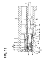
- the locking projection 29 enters the maneuverable groove 59 located before the fastening projection 55 of the locking portion 43 after moving beyond this fastening projection 55 as shown in FIGS. 11 to 13, whereupon the locking portion 43 is at least partly resiliently restored.
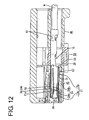
- the fastening projection 55 of the locking portion 43 enters the cut-away portion 21, the lower locking surface 61 is substantially engaged with the rear edge of the locking projection 29 of the front cut end surface 21 a of the cut-away portion 21 (see FIG. 11), and the upper locking surface 58 is substantially engaged with the portions of the front cut end surface 21 a of the cut-away portion 21 at the opposite sides of the locking projection 29 (see FIG. 12).
- the female terminal fitting 10 is held by the locking portion 43 so as not to come out.
- a depth of engagement of the locking portion 43 with the female terminal fitting 10 is increased since the front end of the main portion 11 is pushed down (or toward the locking portion 43) by the jutting portion 49 on the ceiling surface of the cavity 41 to be thereby displaced toward the locking portion 43.
- the upper locking surface 58 of the locking portion 43 is formed in a width range equal to the entire width of the locking portion 43, i.e. the width of the cavity 41, and the front cut end surface 21a of the cut-away portion 21 of the female terminal fitting 10 is extended to the front portion 17a of the outer wall 17 including the locking projection 29 and the front-portion holding piece 30, i.e. in a width range extending over the entire width of the female terminal fitting 10.
- the female terminal fitting 10 is held so as not to come out of the cavity 41 by a strong locking force.
- the front cut end surface 21a of the cut-away portion 21 and the lower locking surface 61 are both inclined at obtuse angles to the withdrawing direction of the female terminal fitting 10, even if a force acts to pull the female terminal fitting 10 backward via the wire W in the locked state, a component of force acts on the locking portion 43 in an obliquely upward or inward direction to the back, i.e. a direction substantially opposite from downward direction which is the deforming direction DD. Thus, it is difficult to disengage the locking portion 43. As a result, a force to lock the terminal fitting 10 is made even stronger.
- the retainer 52 When the retainer 52 is moved to the full locking position (second position) as shown in FIG. 14 after all the female terminal fittings 10 are properly inserted into the corresponding cavities 41, the respective fastening portions 53 enter the corresponding cavities 41 to engage the stepped portions 28 including the projections 27. In this way, the female terminal fittings 10 are preferably doubly locked in the cavities 41 by the locking portions 43 and the retainer 52.
- the terminal fitting 10 may be withdrawn from the female housing 40 for maintenance or other reason.
- the locking portion 43 is forcibly resiliently deformed by the disengagement jig J.
- the disengagement jig J is inserted into the jig-introducing groove 62 and the maneuverable groove 59.
- an initial inserting operation can be easily performed since a wide entrance for the disengagement jig J is provided by the jig-introducing groove 62.
- the back surface of the jig-introducing groove 62 is formed into the guide surface 63 inclined toward the maneuverable groove 59, the disengagement jig J can be smoothly guided to the maneuverable groove 59.
- the wall surface of the maneuverable groove 59 is pushed down to forcibly resiliently deform the arm 54 by the leading end of the disengagement jig J, whereby the locking portion 43 is forcibly resiliently deformed downward as shown in FIG. 16. If the wire W is e.g. gripped and pulled backward or in the withdrawal direction WD when the locking portion 43 is resiliently deformed to be disengaged from the female terminal fitting 10, the female terminal fitting 10 can be pulled out of the cavity 41.
- the angle ⁇ of the upper locking surface 58 of the locking surface 64 to the withdrawing direction of the female terminal fitting 10 is set smaller than the angle ⁇ of the lower locking surface 61 thereto, a trace of displacement of the locking surface 64 during the resilient deformation of the locking portion 43 can be located more backward as compared to a locking surface having the substantially same angle of inclination over the entire length or extension as shown by phantom line in FIGS. 15 and 16.
- the locking surface 64 is more unlikely to interfere with the locking projection 29 during the resilient deformation of the locking surface 64.
- That the trace of displacement of the locking surface 64 during the resilient deformation of the locking portion 43 is located more backward means a smaller clearance between the locking surface 64 of the locking portion 43 and the front cut end surface 21 a of the cut-away portion 21 of the female terminal fitting 10 when the female terminal fitting 10 is inserted to a proper depth in the cavity 41 (see FIG. 11).
- a range within which the female terminal fitting 10 may shake forward and backward or longitudinally while being properly inserted in the cavity 41 becomes smaller. This reduces the possibility of making the electrical connection between the female terminal fitting 10 and the mating terminal fitting unstable.
- the lower locking surface 61 which is the front section of the locking surface 64 with respect to the deforming direction DD of the locking portion 43 is inclined at an obtuse angle to the withdrawing direction WD of the female terminal fitting 10.
- the angle ⁇ of the upper locking surface 58 which is the deforming-direction front section of the locking surface 64, with respect to the withdrawing direction WD of the female terminal fitting 10 is set smaller than the angle ⁇ of the lower locking surface 61 thereto, the trace of displacement of the locking surface 64 during the resilient deformation of the locking portion 43 can be located more backward as compared to a locking surface having the same angle of inclination over the entire length as in the prior art.
- the locking portion 43 is more unlikely to interfere with the female terminal fitting 10 during the resilient deformation of the locking portion 43 at the time of detaching the female terminal fitting 10, making the detaching operability of the female terminal fitting 10 satisfactory or improved. Therefore, according to this preferred embodiment, a large locking force can be secured for the female terminal fitting 10 even if the strength of the locking portion 43 is lowered as a result of miniaturization and the detaching operability of the female terminal fitting 10 can be improved.
- a female housing 40 is provided with one or mroe cavities 41 into which one or more respective female terminal fittings 10 are at least partly insertable preferably from behind.
- a locking portion 43 which is restorable to resiliently engage and lock the female terminal fitting 10 after being resiliently deformed in a direction intersecting with inserting and withdrawing directions of the female terminal fitting 10 upon the insertion of the female terminal fitting 10 is provided in each cavity 41.
- a locking surface 64 of the locking portion 43 engageable with the female terminal fitting 10 is comprised of a lower locking surface 61 as a deforming-direction front section and an upper locking surface 58 as a deforming-direction rear section. An angle of the lower locking surface 61 is inclined at an obtuse angle to the withdrawing direction of the female terminal fitting 10, whereas an angle of the upper locking surface 58 to the withdrawing direction is set smaller than the angle of the lower locking surface 61.
Landscapes
- Connector Housings Or Holding Contact Members (AREA)
Claims (7)
- Verbinder, in welchem, wenn wenigstens ein Anschlußpaßstück (10) wenigstens teilweise in einen entsprechenden Hohlraum (41) eingesetzt ist, welcher in einem Verbindergehäuse (40) zur Verfügung gestellt ist, ein verriegelnder bzw. Verriegelungsabschnitt (43), welcher in dem Hohlraum (41) zur Verfügung gestellt ist, wenigstens teilweise rückgestellt bzw. rückgeführt bzw. wiederhergestellt ist, um rückstellfähig das Anschlußpaßstück (10) zu ergreifen und zu verriegeln, nachdem es rückstellfähig in einer deformierenden Richtung (DD) deformiert bzw. verformt ist bzw. wird, welche Einsetz- und Entnahmerichtung(en) (IWD) des Anschlußpaßstücks (10) schneidet bzw. kreuzt, wobei der verriegelnde Abschnitt (43) an beiden Enden abgestützt bzw. gestützt ist, wobei eine Verriegelungs- bzw. verriegelnde Oberfläche bzw. Fläche (64) des verriegelnden Abschnitts (43), welcher mit dem Anschlußpaßstück (10) in Eingriff bringbar ist, eine erste verriegelnde bzw. Verriegelungsoberfläche bzw. -fläche (58) und eine zweite verriegelnde bzw. Verriegelungsoberfläche bzw. -fläche (61) im wesentlichen anschließend an bzw. kontinuierlich mit die/der erste(n) verriegelnde(n) Oberfläche (58) umfaßt, wobei die erste verriegelnde Oberfläche (58) weiter in den Hohlraum (41) als die zweite verriegelnde Oberfläche (61) vorragt,
wobei der Verbinder dadurch gekennzeichnet ist, daß ein Winkel (β) der ersten verriegelnden Oberfläche (58) zu der Entnahmerichtung (WD) des Anschlußpaßstücks (10) im wesentlichen normal bzw. senkrecht auf die Einsetz- und Entnahmerichtungen (IWD) des Anschlußpaßstücks (10) angeordnet ist; und
die zweite verriegelnde Oberfläche (61) mehr in der Entnahmerichtung (WD) des Anschlußpaßstücks (10) zu ihrem Boden geneigt ist, so daß ein Winkel (α) der zweiten verriegelnden Oberfläche (61) zu der Entnahmerichtung (WD) des Anschlußpaßstücks (10) größer als der Winkel (β) der ersten verriegelnden Oberfläche (58) zur Entnahmerichtung (WD) des Anschlußpaßstücks (10) ist. - Verbinder nach Anspruch 1, wobei das Anschlußpaßstück (10) einen verriegelnden bzw. Verriegelungsvorsprung (29) umfaßt, welcher davon vorragt, welcher mit der zweiten verriegelnden Oberfläche (61) der verriegelnden Oberfläche (64) für ein Verriegeln in Eingriff bringbar ist.
- Verbinder nach einem oder mehreren der vorangehenden Ansprüche, wobei die zweite verriegelnde Oberfläche (61) im wesentlichen in derselben Richtung wie ein Verriegelungs- bzw. verriegelnder Querschnitt bzw. Abschnitt (21 a; 29) des Anschlußpaßstücks (10) geneigt ist.
- Verbinder nach einem oder mehreren der vorangehenden Ansprüche, wobei das Verbindergehäuse (40) mit einer Öffnung (62) ausgebildet ist, welche nach vorne und links bei bzw. nach einem Ausbilden der verriegelnden Oberfläche (64) des verriegelnden Abschnitts (43) offen ist, und wobei ein Querschnitt bzw. Abschnitt (54a) des verriegelnden Abschnitts (43), welcher weiter nach vorne als die verriegelnde Oberfläche (64) ragt, mit wenigstens einer Seitenoberfläche bzw. -fläche der Öffnung (62) verbunden ist.
- Verbinder nach einem oder mehreren der vorangehenden Ansprüche, wobei der Querschnitt (54a) des verriegelnden Abschnitts (43), welcher weiter nach vorne als die verriegelnde Oberfläche (64) vorragt, mit einer betätigbaren Rille bzw. Nut (59) ausgebildet ist, welche im wesentlichen nach vorne offen ist und durch ein Löse-Betätigungselement bzw. -Werkzeug (J) betätigbar ist, um zwangsweise rückstellfähig den verriegelnden Abschnitt (54) zu deformieren bzw. zu verformen.
- Verbinder nach Anspruch 5, wobei das Löse-Betätigungselement (J) in die Öffnung (62) für ein Betätigen der betätigbaren Rille (59) eingesetzt bzw. eingeführt werden kann.
- Verbinder nach Anspruch 5 oder 6, wobei das Betätigungselement einbringende Rille bzw. Nut (62) den Querschnitt (54a) des verriegelnden Abschnitts (43) gabelt, welcher weiter nach vorne als die verriegelnde Oberfläche (64) vorragt.
Applications Claiming Priority (4)
| Application Number | Priority Date | Filing Date | Title |
|---|---|---|---|
| JP2002196441A JP3415140B1 (ja) | 2002-07-04 | 2002-07-04 | コネクタ |
| JP2002196441 | 2002-07-04 | ||
| JP2002213636A JP3415141B1 (ja) | 2002-07-23 | 2002-07-23 | コネクタ |
| JP2002213636 | 2002-07-23 |
Publications (2)
| Publication Number | Publication Date |
|---|---|
| EP1378968A1 EP1378968A1 (de) | 2004-01-07 |
| EP1378968B1 true EP1378968B1 (de) | 2007-11-07 |
Family
ID=28677669
Family Applications (1)
| Application Number | Title | Priority Date | Filing Date |
|---|---|---|---|
| EP02019160A Expired - Lifetime EP1378968B1 (de) | 2002-07-04 | 2002-08-30 | Verbinder |
Country Status (4)
| Country | Link |
|---|---|
| US (1) | US6702614B2 (de) |
| EP (1) | EP1378968B1 (de) |
| CN (1) | CN1268039C (de) |
| DE (1) | DE60223352T2 (de) |
Families Citing this family (17)
| Publication number | Priority date | Publication date | Assignee | Title |
|---|---|---|---|---|
| JP3912204B2 (ja) * | 2002-06-28 | 2007-05-09 | 住友電装株式会社 | コネクタ |
| EP1548892B1 (de) * | 2002-09-25 | 2012-04-04 | Mitsubishi Cable Industries, Ltd. | Elektrischer verbinder |
| JP3745734B2 (ja) * | 2002-12-19 | 2006-02-15 | 矢崎総業株式会社 | コネクタ |
| JP4079042B2 (ja) * | 2003-06-11 | 2008-04-23 | 住友電装株式会社 | 端子金具 |
| JP4442450B2 (ja) * | 2005-02-02 | 2010-03-31 | 住友電装株式会社 | 端子金具 |
| JP2009283212A (ja) * | 2008-05-20 | 2009-12-03 | Yazaki Corp | コネクタ |
| CN101527419B (zh) * | 2009-04-10 | 2011-02-09 | 友达光电(苏州)有限公司 | 维修治具 |
| US8721374B2 (en) * | 2011-07-22 | 2014-05-13 | Lear Corporation | Electrical connector |
| US8951066B2 (en) | 2011-07-22 | 2015-02-10 | Lear Corporation | Electrical connector |
| JP5282156B1 (ja) * | 2012-04-27 | 2013-09-04 | 日本航空電子工業株式会社 | コネクタ |
| JP6004278B2 (ja) * | 2013-04-26 | 2016-10-05 | 住友電装株式会社 | コネクタ |
| JP5708837B1 (ja) * | 2014-02-06 | 2015-04-30 | 第一精工株式会社 | コネクタ端子 |
| CN104852197B (zh) * | 2014-02-14 | 2018-06-01 | 国基电子(上海)有限公司 | 接口装置 |
| JP6551204B2 (ja) * | 2015-12-14 | 2019-07-31 | 住友電装株式会社 | 端子金具 |
| JP6670446B2 (ja) * | 2016-06-15 | 2020-03-25 | 株式会社オートネットワーク技術研究所 | コネクタ |
| CN114533007B (zh) * | 2016-08-31 | 2024-05-24 | 尼普洛株式会社 | 导丝和制造导丝的方法 |
| JP6886447B2 (ja) * | 2018-10-29 | 2021-06-16 | 矢崎総業株式会社 | コネクタ、及び、ワイヤハーネス |
Citations (4)
| Publication number | Priority date | Publication date | Assignee | Title |
|---|---|---|---|---|
| US5575684A (en) * | 1994-04-08 | 1996-11-19 | Yazaki Corporation | Connector housing |
| EP0863578A2 (de) * | 1997-03-03 | 1998-09-09 | Sumitomo Wiring Systems, Ltd. | Elastisch befestigtes elektrisches Kontaktelement |
| US5885105A (en) * | 1996-03-07 | 1999-03-23 | Yazaki Corporation | Terminal-locking device-equipped connector |
| EP1294056A2 (de) * | 2001-09-07 | 2003-03-19 | Sumitomo Wiring Systems, Ltd. | Anschlusskontakt, damit ausgestatteter Steckverbinder und Herstellungsverfahren des Anschlusskontaktes |
Family Cites Families (7)
| Publication number | Priority date | Publication date | Assignee | Title |
|---|---|---|---|---|
| US5235743A (en) | 1990-07-11 | 1993-08-17 | Yazaki Corporation | Method of manufacturing a pair of terminals having a low friction material on a mating surface to facilitate connection of the terminals |
| JP2596032Y2 (ja) * | 1991-09-26 | 1999-06-07 | 矢崎総業株式会社 | コネクタ |
| JP2868405B2 (ja) * | 1994-02-16 | 1999-03-10 | 矢崎総業株式会社 | 雌型端子 |
| JPH08321345A (ja) * | 1995-05-24 | 1996-12-03 | Yazaki Corp | コネクタハウジング |
| JP2001052794A (ja) * | 1999-07-26 | 2001-02-23 | Thomas & Betts Corp <T&B> | コネクタ |
| JP3804040B2 (ja) * | 1999-12-07 | 2006-08-02 | 矢崎総業株式会社 | フロントホルダを有するコネクタ装置 |
| JP3495020B2 (ja) * | 2000-11-24 | 2004-02-09 | 矢崎総業株式会社 | コネクタ |
-
2002
- 2002-08-30 DE DE60223352T patent/DE60223352T2/de not_active Expired - Lifetime
- 2002-08-30 EP EP02019160A patent/EP1378968B1/de not_active Expired - Lifetime
- 2002-10-15 US US10/271,802 patent/US6702614B2/en not_active Expired - Lifetime
-
2003
- 2003-01-17 CN CNB031007317A patent/CN1268039C/zh not_active Expired - Lifetime
Patent Citations (4)
| Publication number | Priority date | Publication date | Assignee | Title |
|---|---|---|---|---|
| US5575684A (en) * | 1994-04-08 | 1996-11-19 | Yazaki Corporation | Connector housing |
| US5885105A (en) * | 1996-03-07 | 1999-03-23 | Yazaki Corporation | Terminal-locking device-equipped connector |
| EP0863578A2 (de) * | 1997-03-03 | 1998-09-09 | Sumitomo Wiring Systems, Ltd. | Elastisch befestigtes elektrisches Kontaktelement |
| EP1294056A2 (de) * | 2001-09-07 | 2003-03-19 | Sumitomo Wiring Systems, Ltd. | Anschlusskontakt, damit ausgestatteter Steckverbinder und Herstellungsverfahren des Anschlusskontaktes |
Also Published As
| Publication number | Publication date |
|---|---|
| US20030190841A1 (en) | 2003-10-09 |
| EP1378968A1 (de) | 2004-01-07 |
| DE60223352D1 (de) | 2007-12-20 |
| CN1268039C (zh) | 2006-08-02 |
| CN1467878A (zh) | 2004-01-14 |
| DE60223352T2 (de) | 2008-08-28 |
| US6702614B2 (en) | 2004-03-09 |
Similar Documents
| Publication | Publication Date | Title |
|---|---|---|
| EP1369959B1 (de) | Ein Steckverbinder, ein Entriegelungsorgan und ein Verfahren | |
| EP1378968B1 (de) | Verbinder | |
| US7347747B2 (en) | Terminal fitting with a resilient reinforcing piece | |
| US7014505B1 (en) | Connector | |
| US6835097B2 (en) | Connector | |
| EP1369962B1 (de) | Ein Anschlusskontakt und ein beipassender Steckverbinder | |
| EP1863135A2 (de) | Steckverbinder und Entsperrvorrichtung dafür | |
| US6872093B2 (en) | Terminal fitting and a connector provided therewith | |
| EP1294056B1 (de) | Anschlusskontakt, damit ausgestatteter Steckverbinder und Herstellungsverfahren des Anschlusskontaktes | |
| US6817904B2 (en) | Connector and a method for inserting a terminal fitting thereinto | |
| EP1376768B1 (de) | Ein elektrischer Steckverbinder | |
| US6948986B2 (en) | Connector | |
| US6851976B2 (en) | Connector, a terminal fitting and a method for inserting a terminal fitting | |
| US6939171B2 (en) | Connector, molding method therefor and molding apparatus therefor | |
| EP1369961B1 (de) | Ein Anschlusskontakt und ein Steckverbinder | |
| EP1391970B1 (de) | Verbinder | |
| EP1577981B1 (de) | Verbinder und Demontagevorrichtung | |
| JP2004055513A (ja) | コネクタ |
Legal Events
| Date | Code | Title | Description |
|---|---|---|---|
| PUAI | Public reference made under article 153(3) epc to a published international application that has entered the european phase |
Free format text: ORIGINAL CODE: 0009012 |
|
| 17P | Request for examination filed |
Effective date: 20020905 |
|
| AK | Designated contracting states |
Kind code of ref document: A1 Designated state(s): AT BE BG CH CY CZ DE DK EE ES FI FR GB GR IE IT LI LU MC NL PT SE SK TR |
|
| AX | Request for extension of the european patent |
Extension state: AL LT LV MK RO SI |
|
| AKX | Designation fees paid |
Designated state(s): DE FR |
|
| GRAP | Despatch of communication of intention to grant a patent |
Free format text: ORIGINAL CODE: EPIDOSNIGR1 |
|
| RIN1 | Information on inventor provided before grant (corrected) |
Inventor name: ISHIKAWA, RYOTARO,C/O SUMITOMO WIRING SYSTEMS, LTD Inventor name: NANKOU, YUUICHI,C/O SUMITOMO WIRING SYSTEMS, LTD. Inventor name: KAWASE, HAJIME,C/O SUMITOMO WIRING SYSTEMS, LTD. Inventor name: NAKAMURA, HIDETO,C/O SUMITOMO WIRING SYSTEMS, LTD. |
|
| GRAS | Grant fee paid |
Free format text: ORIGINAL CODE: EPIDOSNIGR3 |
|
| GRAA | (expected) grant |
Free format text: ORIGINAL CODE: 0009210 |
|
| AK | Designated contracting states |
Kind code of ref document: B1 Designated state(s): DE FR |
|
| REF | Corresponds to: |
Ref document number: 60223352 Country of ref document: DE Date of ref document: 20071220 Kind code of ref document: P |
|
| ET | Fr: translation filed | ||
| PLBE | No opposition filed within time limit |
Free format text: ORIGINAL CODE: 0009261 |
|
| STAA | Information on the status of an ep patent application or granted ep patent |
Free format text: STATUS: NO OPPOSITION FILED WITHIN TIME LIMIT |
|
| 26N | No opposition filed |
Effective date: 20080808 |
|
| REG | Reference to a national code |
Ref country code: FR Ref legal event code: PLFP Year of fee payment: 15 |
|
| REG | Reference to a national code |
Ref country code: DE Ref legal event code: R084 Ref document number: 60223352 Country of ref document: DE |
|
| REG | Reference to a national code |
Ref country code: FR Ref legal event code: PLFP Year of fee payment: 16 |
|
| REG | Reference to a national code |
Ref country code: FR Ref legal event code: PLFP Year of fee payment: 17 |
|
| PGFP | Annual fee paid to national office [announced via postgrant information from national office to epo] |
Ref country code: FR Payment date: 20210715 Year of fee payment: 20 |
|
| PGFP | Annual fee paid to national office [announced via postgrant information from national office to epo] |
Ref country code: DE Payment date: 20210720 Year of fee payment: 20 |
|
| REG | Reference to a national code |
Ref country code: DE Ref legal event code: R071 Ref document number: 60223352 Country of ref document: DE |