WO2017208935A1 - 再現色プロファイル補正装置、再現色プロファイル補正方法、再現色プロファイル補正プログラム、及び再現色プロファイル補正プログラムを含むコンピュータ可読媒体 - Google Patents
再現色プロファイル補正装置、再現色プロファイル補正方法、再現色プロファイル補正プログラム、及び再現色プロファイル補正プログラムを含むコンピュータ可読媒体 Download PDFInfo
- Publication number
- WO2017208935A1 WO2017208935A1 PCT/JP2017/019388 JP2017019388W WO2017208935A1 WO 2017208935 A1 WO2017208935 A1 WO 2017208935A1 JP 2017019388 W JP2017019388 W JP 2017019388W WO 2017208935 A1 WO2017208935 A1 WO 2017208935A1
- Authority
- WO
- WIPO (PCT)
- Prior art keywords
- color
- ink
- combination
- colorimetric value
- value
- Prior art date
- Legal status (The legal status is an assumption and is not a legal conclusion. Google has not performed a legal analysis and makes no representation as to the accuracy of the status listed.)
- Ceased
Links
Images






Classifications
-
- H—ELECTRICITY
- H04—ELECTRIC COMMUNICATION TECHNIQUE
- H04N—PICTORIAL COMMUNICATION, e.g. TELEVISION
- H04N1/00—Scanning, transmission or reproduction of documents or the like, e.g. facsimile transmission; Details thereof
- H04N1/46—Colour picture communication systems
- H04N1/56—Processing of colour picture signals
- H04N1/60—Colour correction or control
- H04N1/603—Colour correction or control controlled by characteristics of the picture signal generator or the picture reproducer
- H04N1/6033—Colour correction or control controlled by characteristics of the picture signal generator or the picture reproducer using test pattern analysis
-
- H—ELECTRICITY
- H04—ELECTRIC COMMUNICATION TECHNIQUE
- H04N—PICTORIAL COMMUNICATION, e.g. TELEVISION
- H04N1/00—Scanning, transmission or reproduction of documents or the like, e.g. facsimile transmission; Details thereof
- H04N1/40—Picture signal circuits
-
- G—PHYSICS
- G06—COMPUTING OR CALCULATING; COUNTING
- G06F—ELECTRIC DIGITAL DATA PROCESSING
- G06F3/00—Input arrangements for transferring data to be processed into a form capable of being handled by the computer; Output arrangements for transferring data from processing unit to output unit, e.g. interface arrangements
- G06F3/12—Digital output to print unit, e.g. line printer, chain printer
- G06F3/1201—Dedicated interfaces to print systems
- G06F3/1202—Dedicated interfaces to print systems specifically adapted to achieve a particular effect
- G06F3/1203—Improving or facilitating administration, e.g. print management
- G06F3/1208—Improving or facilitating administration, e.g. print management resulting in improved quality of the output result, e.g. print layout, colours, workflows, print preview
-
- G—PHYSICS
- G06—COMPUTING OR CALCULATING; COUNTING
- G06T—IMAGE DATA PROCESSING OR GENERATION, IN GENERAL
- G06T1/00—General purpose image data processing
-
- H—ELECTRICITY
- H04—ELECTRIC COMMUNICATION TECHNIQUE
- H04N—PICTORIAL COMMUNICATION, e.g. TELEVISION
- H04N1/00—Scanning, transmission or reproduction of documents or the like, e.g. facsimile transmission; Details thereof
- H04N1/46—Colour picture communication systems
-
- H—ELECTRICITY
- H04—ELECTRIC COMMUNICATION TECHNIQUE
- H04N—PICTORIAL COMMUNICATION, e.g. TELEVISION
- H04N1/00—Scanning, transmission or reproduction of documents or the like, e.g. facsimile transmission; Details thereof
- H04N1/46—Colour picture communication systems
- H04N1/56—Processing of colour picture signals
- H04N1/60—Colour correction or control
-
- H—ELECTRICITY
- H04—ELECTRIC COMMUNICATION TECHNIQUE
- H04N—PICTORIAL COMMUNICATION, e.g. TELEVISION
- H04N1/00—Scanning, transmission or reproduction of documents or the like, e.g. facsimile transmission; Details thereof
- H04N1/46—Colour picture communication systems
- H04N1/56—Processing of colour picture signals
- H04N1/60—Colour correction or control
- H04N1/6011—Colour correction or control with simulation on a subsidiary picture reproducer
-
- H—ELECTRICITY
- H04—ELECTRIC COMMUNICATION TECHNIQUE
- H04N—PICTORIAL COMMUNICATION, e.g. TELEVISION
- H04N1/00—Scanning, transmission or reproduction of documents or the like, e.g. facsimile transmission; Details thereof
- H04N1/46—Colour picture communication systems
- H04N1/56—Processing of colour picture signals
- H04N1/60—Colour correction or control
- H04N1/6083—Colour correction or control controlled by factors external to the apparatus
- H04N1/6088—Colour correction or control controlled by factors external to the apparatus by viewing conditions, i.e. conditions at picture output
-
- B—PERFORMING OPERATIONS; TRANSPORTING
- B41—PRINTING; LINING MACHINES; TYPEWRITERS; STAMPS
- B41J—TYPEWRITERS; SELECTIVE PRINTING MECHANISMS, i.e. MECHANISMS PRINTING OTHERWISE THAN FROM A FORME; CORRECTION OF TYPOGRAPHICAL ERRORS
- B41J2/00—Typewriters or selective printing mechanisms characterised by the printing or marking process for which they are designed
- B41J2/525—Arrangement for multi-colour printing, not covered by group B41J2/21, e.g. applicable to two or more kinds of printing or marking process
-
- G—PHYSICS
- G06—COMPUTING OR CALCULATING; COUNTING
- G06F—ELECTRIC DIGITAL DATA PROCESSING
- G06F3/00—Input arrangements for transferring data to be processed into a form capable of being handled by the computer; Output arrangements for transferring data from processing unit to output unit, e.g. interface arrangements
- G06F3/12—Digital output to print unit, e.g. line printer, chain printer
- G06F3/1201—Dedicated interfaces to print systems
- G06F3/1223—Dedicated interfaces to print systems specifically adapted to use a particular technique
- G06F3/1237—Print job management
- G06F3/1244—Job translation or job parsing, e.g. page banding
- G06F3/1245—Job translation or job parsing, e.g. page banding by conversion to intermediate or common format
-
- H—ELECTRICITY
- H04—ELECTRIC COMMUNICATION TECHNIQUE
- H04N—PICTORIAL COMMUNICATION, e.g. TELEVISION
- H04N1/00—Scanning, transmission or reproduction of documents or the like, e.g. facsimile transmission; Details thereof
- H04N1/46—Colour picture communication systems
- H04N1/56—Processing of colour picture signals
- H04N1/60—Colour correction or control
- H04N1/6002—Corrections within particular colour systems
- H04N1/6008—Corrections within particular colour systems with primary colour signals, e.g. RGB or CMY(K)
Definitions
- the present invention relates to a reproduction color profile correction apparatus for spot color DDCP, a reproduction color profile correction method, a reproduction color profile correction program, and a computer readable medium including a reproduction color profile correction program.
- a color reproduction color profile in a printed matter output by the output device is created (for example, Patent Document 1). And Patent Document 2).
- a color chart composed of a predetermined combination of control values for each ink is output from the output device for profile generation.
- each of the charts for each combination of ink control values is color-measured, and the measured colorimetric value which is the measured colorimetric value and the combination of the ink control value corresponding to this colorimetric value Acquire the correspondence and create a reproduction color profile.
- the reproduction color profile corresponding to the process ink manages the reproduction color by multiplying the inks of the process inks that are usually used, for example, C (Cyan) M (Magenta) Y (Yellow) K (Black) color components.
- the reproduction color profile corresponding to the process ink is generated by printing a color chart of combinations of control values of the process ink of each color component in advance and measuring the measured colorimetric values.
- the special color ink when used in combination with the process ink, the special color used for each printed matter is determined for the special color. For this reason, when combining special color inks with process ink combinations, it is not possible to print a color chart in advance and obtain measured colorimetric values from the printed color chart as in the case of only process ink combinations. . That is, unlike the case of combining only process inks, in the case of combining special color inks, it is practically impossible to obtain a measured colorimetric value from an actually printed color chart and create a reproduction color profile.
- the colorimetric value of the reproduced color in this combination is predicted, and the predicted colorimetric value of the prediction result is used to generate the reproduced color profile.
- the reproduction color prediction for example, parameters such as the measured colorimetric value of the spot color solid and the dot gain of the halftone dot are input to the reproduction color prediction model (or color prediction model) of the color prediction system, and the special color ink is input. Predicted colorimetric values of reproduced colors obtained by combining each other or process ink and special color ink are obtained. Then, based on the predicted colorimetric value predicted by the color prediction system, a reproduction color profile corresponding to the printed matter by the combination of the process ink and the special color ink is generated.
- the color prediction system obtains a predicted colorimetric value using a reproduction color prediction model using a solid measured colorimetric value of the process ink even for a combination of only process inks. Since this predicted colorimetric value is obtained from the limited information using a reproduction color prediction model, it may not match the measured colorimetric value obtained by actually measuring the color chart. That is, it is conceivable that the reproduced color profile created from the predicted colorimetric value has lower reproduction color accuracy than the reproduced color profile created from the measured colorimetric value obtained from the color chart.
- the predicted colorimetric value of the reproduced color combining process ink and spot color ink cannot reflect the correction by the measured colorimetric value, and remains as the predicted colorimetric value predicted by the reproduced color prediction model. Become.
- the predicted colorimetric values predicted by the reproduced color prediction model and the measured colorimetric values obtained from the color chart are mixed in the same reproduced color profile, so the consistency of the measured color values in the reproduced color profile can be achieved. Absent.
- the reproduction color of the combination of the special color ink and the process ink does not reflect the measurement colorimetric value of the process ink, so that the reproduction color of only the combination of the process ink only When compared, it becomes an unnatural color and cannot be consistent.
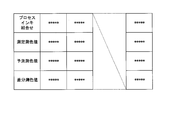
- FIG. 9 shows an evaluation chart for comparing the reproduced colors of the special color ink and the process ink.
- the image which reproduced the colorimetric value at the time of doing is shown.
- special color inks for example, yellow green, brown, etc.
- the colorimetric values when they are included in a combination of process ink flat meshes are reproduced by increasing 80% ⁇ 100%.
- the colorimetric values are reproduced as they are in the combination of the flat meshes of process ink.
- the colorimetric values are changed from the predicted colorimetric values to the measured colorimetric values.
- the colorimetric values that can be corrected and reproduced by the combination of process inks are accurately expressed.
- the area A is a colorimetric value of the reproduced color by the combination of the process ink and the special color ink, the predicted colorimetric value corresponding to the measured colorimetric value of the process ink cannot be simulated, and the original reproduced color prediction is performed.
- the predicted colorimetric value obtained by the model remains unchanged.
- the present invention has been made in view of such a situation, and in the case of only process ink and the combination of process ink and special color ink, based on the measured colorimetric values obtained from the color chart of only the combination of process inks.
- a reproduction color profile correction device, a reproduction color profile correction method, and a program capable of performing correction with matching reproduction color between each of the reproduction color profile and the reproduction color profile created from the predicted colorimetric values are provided. To do.
- the reproduction color profile correction apparatus of the present invention measures the reproduction color by an ink combination comprising a process ink combination which is a combination of process ink control values and a special color ink combination which is a combination of control values of the special color ink in the reproduction color profile.
- a reproduction color profile correction apparatus for correcting a color value, a predicted colorimetric value which is a colorimetric value of a reproduction color predicted corresponding to the process ink combination in the ink combination, and a color chart corresponding to the process ink combination
- a difference colorimetric value calculation unit that calculates a difference colorimetric value that is a difference from a measured colorimetric value that is a colorimetric value obtained by measuring the reproduction color of the image; and a predicted measurement of the reproduction color in the ink combination by the difference colorimetry value
- a colorimetric value correction unit for correcting the color value.
- the reproduction color profile correction apparatus is a colorimetric measurement of a combination in which the control values of the process inks of the process ink combination are distributed in a predetermined color space for each halftone dot area ratio of the special color ink in the ink combination.
- An inclusion area extraction unit that extracts an inclusion area that includes a value
- an adjustment coefficient calculation unit that calculates an adjustment coefficient to be multiplied by the difference colorimetric value for each control value of the spot color ink based on the size of the inclusion area With.
- the colorimetric value correction unit multiplies the difference colorimetric value by the adjustment coefficient corresponding to the spot color ink combination, and the spot color ink having the spot color ink combination.
- the predicted colorimetric value is corrected.
- the adjustment coefficient calculation unit has each process ink distributed in a predetermined color space when the size of the inclusion area is a halftone dot area ratio of the special color ink is “0”.
- the size of the inclusion area including the colorimetric values of the combinations having different halftone dot area ratios is used as a reference value, and the size of the inclusion area for each dot area ratio of the spot color ink is divided by the reference value. Calculate the adjustment factor.
- the size of the inclusion area is the volume of the inclusion area in the predetermined color space.
- the size of the inclusion area is an area of a projection plane when the inclusion area in the predetermined color space is projected onto a two-dimensional plane.
- the size of the inclusion region is a length of a diagonal line of a rectangular parallelepiped that includes the distribution of the colorimetric values in the predetermined color space.
- the reproduction color profile correction method of the present invention is a method for measuring a reproduction color by an ink combination comprising a process ink combination that is a combination of process ink control values and a special color ink combination that is a combination of control values of special color inks in the reproduction color profile.
- a reproduced color profile correction method for correcting a color value wherein the difference colorimetric value calculation unit is a predicted colorimetric value that is a colorimetric value of a reproduced color predicted corresponding to the process ink combination in the ink combination, and A difference colorimetric value calculation process for calculating a difference colorimetric value that is a difference from a measured colorimetric value that is a colorimetric value obtained by measuring a reproduction color of a color chart corresponding to a process ink combination, and a colorimetric value correction unit, And a colorimetric value correction process for correcting the predicted colorimetric value of the reproduced color in the ink combination based on the difference colorimetric value.
- the program of the present invention corrects a colorimetric value of a reproduced color by an ink combination consisting of a process ink combination which is a combination of process ink control values and a special color ink combination which is a combination of control values of special color ink in a reproduction color profile.
- a reproduction color profile correction program for causing a computer to function as a reproduction color profile correction system to perform, a predicted colorimetric value which is a colorimetric value of a reproduction color predicted corresponding to a process ink combination in the ink combination, and the process ink
- a difference colorimetric value that is a difference from a measured colorimetric value that is a colorimetric value obtained by measuring a reproduced color of a color chart corresponding to the combination is calculated, and a predicted colorimetric of a reproduced color in the ink combination is calculated by the difference colorimetric value Operate the computer to perform a reproduction color profile correction method that corrects the value. It is a reproduction color profile correction program.
- the computer-readable medium of the present invention provides a colorimetric value of a reproduced color by an ink combination comprising a process ink combination that is a combination of process ink control values and a special color ink combination that is a combination of control values of special color ink in a reproduction color profile.
- a computer functions and a predicted colorimetric value that is a colorimetric value of a reproduced color predicted corresponding to the process ink combination in the ink combination and a color corresponding to the process ink combination Calculating a difference colorimetric value that is a difference from a measured colorimetric value that is a colorimetric value obtained by measuring the reproduced color of the chart, and correcting the predicted colorimetric value of the reproduced color in the ink combination by the difference colorimetric value;
- a reproduction color profile correction program that operates the computer to perform the reproduction color profile correction method. Including the ram.
- each of the process ink alone and the combination of the process ink and the special color ink is used. It is possible to provide a reproduction color profile correction apparatus, a reproduction color profile correction method, and a program capable of performing correction with matching of reproduction colors between reproduction color profiles created from predicted colorimetric values. It becomes.
- FIG. 3 is a diagram illustrating a configuration example of a difference colorimetric value table stored in a difference colorimetric value storage unit 16.
- FIG. It is a figure explaining correction
- 5 is a flowchart illustrating an operation example of correction of a reproduction color profile in the first embodiment. It is a block diagram which shows the structural example of the reproduction color profile correction system 1A by the 2nd Embodiment of this invention.
- a control value for example, halftone dot area ratio
- a control value for controlling the gradation of each ink of each channel of process ink and special color ink is constant in the color prediction table constituting the reproduction color profile.
- the process ink combination indicates a combination of ink control values of each color component (CMYK) in the process ink.
- the special color ink combination indicates a combination of control values of one or two or more special color inks.
- the ink combination indicates a combination of a process ink combination and a special color ink combination.
- the colorimetric values of the process ink combination many combinations of control values are printed as a color chart, and the colorimetric values of the color chart (hereinafter also referred to as a chart) corresponding to each combination are measured as the colorimetric values. It has been measured.
- a special color ink combination is included, there is no color chart printed with an ink combination including a process ink combination and a special color ink combination.
- a spot color ink combination when a spot color ink combination is included, it corresponds to the grid point of each control value of each channel of the process ink and the spot color ink by simulation using a general reproduction color prediction model. The predicted colorimetric value reproduced by printing with the ink combination to be obtained is obtained.
- FIG. 1 is a block diagram showing a configuration example of a reproduction color profile correction system (reproduction color profile correction apparatus) 1 according to the first embodiment of the present invention.
- a reproduction color profile correction system 1 includes an input / output unit 11, a difference colorimetric value calculation unit 12, a colorimetry value correction unit 13, a reproduction color profile storage unit 14, a measurement colorimetry value storage unit 15, and a difference colorimetry.
- Each of the value storage units 16 is provided.
- a space indicating colorimetric values is described as an L * a * b * color space.
- the input / output unit 11 reads the reproduction color profile obtained from the predicted colorimetric value supplied from the external device, and writes and stores it in the reproduction color profile storage unit 14.
- the reproduction color profile is generated by, for example, a predicted colorimetric value obtained by simulation using a reproduction color prediction model, and an ink combination including a combination of process ink and special color ink by CMYK, and the ink combination.
- the table configuration corresponds to the predicted colorimetric value of the reproduced color by the combination.
- any reproduction color prediction model may be used as long as the predicted colorimetric value of the ink combination can be obtained by simulation.
- the input / output unit 11 reads a measured colorimetric value (measured colorimetric value table described later) supplied from an external device, and writes and stores it in the measured colorimetric value storage unit 15.
- the measured colorimetric value in the present embodiment is a colorimetric value measured for each process ink combination from a reproduction color chart obtained by actually printing the process ink combinations of the control values of the process inks of CMYK.
- the measured colorimetric values are supplied as a measured colorimetric value table in which the combinations of the control values of CMYK and the measured colorimetric values measured from the chart of this combination are described correspondingly.
- the input / output unit 11 outputs a control command supplied from the outside to each unit of the reproduction color profile correction system 1.
- the difference colorimetric value calculation unit 12 sequentially reads the measurement colorimetry value and the process ink combination corresponding to the measurement colorimetry value (the control value of each process ink) from the measurement colorimetry value table of the measurement colorimetry value storage unit 15. Each). Then, the difference colorimetric value calculation unit 12 searches the reproduction color profile table of the reproduction color profile storage unit 14 for an ink combination of only the same process ink combination as this process ink combination. Here, the ink combination of only the process ink combination indicates an ink combination in which the control value of the special color ink is “0”. The difference colorimetric value calculation unit 12 reads the predicted colorimetric value of the searched process ink combination from the reproduction color profile table. As shown below, the difference colorimetric value calculation unit 12 subtracts the predicted colorimetric value from the measured colorimetric value to obtain a difference colorimetric value that is the difference between the measured colorimetric value and the predicted colorimetric value.
- Difference prediction value ( ⁇ L 1 , ⁇ a 1 , ⁇ b 1 ) Measured colorimetric values (L 1 , a 1 , b 1 ) ⁇ predicted colorimetric values (L 1 — 0 , a 1 — 0 , b 1 — 0 )
- ⁇ L 1 L 1 -L 1_0
- ⁇ a a 1 -a 1_0
- a ⁇ b b 1 -b 1_0.
- the difference colorimetric value calculation unit 12 associates the obtained difference colorimetry value with the process ink combination together with each of the measurement colorimetry value and the predicted colorimetry value, and the difference colorimetry value table of the difference colorimetry value storage unit 16 Write to and store.
- FIG. 2 is a diagram illustrating a configuration example of a difference colorimetric value table stored in the difference colorimetric value storage unit 16.
- the difference colorimetry value table stores a process ink combination and each of the measurement colorimetry value, the predicted colorimetry value, and the difference colorimetry value corresponding to the process ink combination as a pair. That is, for each combination of process inks, that is, combinations of control values for each process ink of CMYK, a differential colorimetric value that is the difference between the measured colorimetric value and the predicted colorimetric value is obtained and stored.
- the colorimetric value correction unit 13 sequentially selects the process ink combination and the difference colorimetric value (L 1 , a corresponding to this process ink combination) from the difference colorimetry value table of the difference colorimetry value storage unit 16. 1 and b 1 ) are read out. Then, the colorimetric value correction unit 13 detects an ink combination having the same process ink combination as the read process ink combination from the reproduction color profile table of the reproduction color profile storage unit 14.
- Colorimetric value correction unit 13 the predicted colorimetric values of the detected ink combination each (L 1_n, a 1_n, b 1_n) reads the read predicted colorimetric values (L 1_n, a 1_n, b 1_n) to Then, the difference colorimetric value of the process ink combination is added.
- the colorimetric value correction unit 13 adds the corrected colorimetric values (L 1 — n ′, a 1 — n ′, b 1 — n ′) obtained by the addition to the predicted colorimetric values (L 1 — n , a 1 — n ) to be added to the reproduction color profile table.
- L 1 — n ′ L 1 — n + ⁇ L 1
- a 1 — n ′ a 1 — n + ⁇ a 1
- b 1 — n ′ b 1 — n + ⁇ b 1
- N is an integer from 1 to m
- m is the number of ink combinations having the same process ink combination.
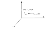
- FIG. 3 is a diagram illustrating correction of colorimetric values in the L * a * b * color space in the present embodiment.
- difference colorimetric values ⁇ L 1 , ⁇ a 1 , ⁇ b
- L 1 , a 1 , b 1 measured colorimetric values
- predicted colorimetric values L 1 — 0 , a 1 — 0 , b 1 — 0 ). 1
- the difference colorimetric values ( ⁇ L 1 , ⁇ a 1 , ⁇ b 1 ) are the coordinate points of the predicted colorimetric values (L 1 — 0 , a 1 — 0 , b 1 — 0 ) in the L * a * b * color space and the measured colorimetric values ( L 1 , a 1 , b 1 ) represents a difference vector from the coordinate point.
- the predicted colorimetric values (L 1 — 0 , a 1 — 0 , b 1 — 0 ) indicate predicted colorimetric values where the control value of the special color ink in the special color ink combination is “0”.
- the predicted colorimetric values (L 1 — 0 , a 1 — 0 , b 1 — 0 ) are the same ink combinations (process inks) as the process color combinations of the measured colorimetric values (L 1 , a 1 , b 1 ) measured on the color chart. Only combination).
- the colorimetric value correction unit 13 corrects the predicted colorimetric value of the ink combination having the same process ink combination as the process ink combination, using the difference colorimetric values ( ⁇ L 1 , ⁇ a 1 , ⁇ b 1 ). Correct to colorimetric values. That is, if the process ink combination is the same, the colorimetric value correction unit 13 includes the difference colorimetric values ( ⁇ L 1 , ⁇ a) including the predicted colorimetric values of each ink combination for which the control value of the special color ink is not “0”. 1 , ⁇ b 1 ).
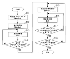
- FIG. 4 is a flowchart illustrating an operation example of the reproduction color profile correction according to the first embodiment.
- Step S11 The input / output unit 11 writes and stores a reproduction color profile (reproduction color profile table) supplied from the outside in the reproduction color profile storage unit 14.
- Step S12 The input / output unit 11 writes and stores in the measured colorimetric value storage unit 15 each of the measured colorimetric values, which are supplied from the outside and measure the reproduction color of the chart for each process ink combination in the color chart.
- the input / output unit 11 creates a measurement colorimetric value storage unit 15 by using a measurement colorimetry value table that is a pair of a process ink combination that reproduces a reproduction color and a measurement colorimetry value of the reproduction color by this process ink combination. Write to and store.
- Step S13 The difference colorimetric value calculation unit 12 reads the process ink combinations in the order described from the measurement colorimetry value table of the measurement colorimetry value storage unit 15 and the measurement colorimetry values (L 1) of the reproduced colors of this process ink combination. , A 1 , b 1 ). Then, the difference colorimetric value calculation unit 12 generates an ink combination having the same process ink combination as the process ink combination and having a control value of the special color ink combination of “0” as a reproduction color profile of the reproduction color profile storage unit 14. Detect in the table.
- the difference colorimetric value calculation unit 12 reads the predicted colorimetric values (L 1 — 0 , a 1 — 0 , b 1 — 0 ) stored corresponding to the detected ink combination from the measured colorimetric value table.
- the difference colorimetric value calculation unit 12 subtracts the predicted colorimetric values (L 1 — 0 , a 1 — 0 , b 1 — 0 ) from the measured colorimetric values (L 1 , a 1 , b 1 ) to obtain the difference colorimetric values ( ⁇ L 1 , ⁇ a 1 , ⁇ b 1 ) is calculated.
- the differential colorimetric value calculation unit 12 calculates the differential colorimetric values ( ⁇ L 1 , ⁇ a 1 , ⁇ b 1 ), the process ink combination, the measured colorimetric values (L 1 , a 1 , b 1 ), and the predictive measurement.
- the color values (L 1 — 0 , a 1 — 0 , b 1 — 0 ) are associated with each other, and are written and stored in the differential colorimetric value table of the differential colorimetric value storage unit 16.
- Step S14 The difference colorimetric value calculation unit 12 determines whether or not the calculation of the difference colorimetry values corresponding to all the process ink combinations described in the measurement colorimetry value table of the measurement colorimetry value storage unit 15 has been completed. Do. At this time, if the difference colorimetric value calculation unit 12 has finished calculating the difference colorimetric values corresponding to all the process ink combinations described in the measurement colorimetry value table, the process proceeds to step S15. On the other hand, if the calculation of the difference colorimetric values corresponding to all the process ink combinations described in the measurement colorimetry value table has not been completed, the difference colorimetry value calculation unit 12 advances the process to step S13.
- Step S15 The colorimetric value correction unit 13 reads out each of the process ink combinations and the difference colorimetric values corresponding to the process ink combinations in the order described from the difference colorimetry value table of the difference colorimetry value storage unit 16. .
- Step S16 Next, the colorimetric value correction unit 13 detects an ink combination having the same process ink combination as the target process ink combination from the reproduction color profile table of the reproduction color profile storage unit 14.
- the target process ink combination indicates a process ink combination read out in the order described from the difference colorimetric value table of the difference colorimetric value storage unit 16.
- the colorimetric value correction unit 13 detects ink combinations having the same process ink combination as the target process ink combination in the order described in the reproduction color profile table.
- the colorimetric value correction unit 13 reads predicted colorimetric values (L 1 — n , a 1 — n , b 1 — n ) corresponding to the detected ink combination from the reproduction color profile table.
- the colorimetric value correction unit 13 adds the difference colorimetric values ( ⁇ L 1 , ⁇ a 1 , ⁇ b 1 ) to the read predicted colorimetric values (L 1 — n , a 1 — n , b 1 — n ), thereby correcting the colorimetric values.
- (L 1 — n ′, a 1 — n ′, b 1 — n ′) is calculated.
- the colorimetric value correction unit 13 uses the corrected colorimetric values (L 1 — n ′, a 1 — n ′, b 1 — n ′) as predicted colorimetric values (L 1 — n , a 1 — n , b 1 — n ) of the reproduction color profile table.
- the reproduction color profile table is corrected by overwriting.
- Step S17 The colorimetric value correction unit 13 determines whether or not correction of all predicted colorimetric values of the ink combination having the same process ink combination as the target process ink combination has been completed in the reproduction color profile table. At this time, if the correction of all predicted colorimetric values of the ink combination having the same process ink combination as the target process ink combination is completed, the colorimetric value correction unit 13 advances the process to step S18. On the other hand, if the correction of all predicted colorimetric values of the ink combination having the same process ink combination as the target process ink combination has not been completed, the colorimetric value correction unit 13 advances the process to step S16, and reproduces the color profile. The predicted colorimetric values of the remaining ink combinations in the table are corrected.
- Step S18 The colorimetric value correction unit 13 determines whether or not the reading of the differential colorimetric values of all process ink combinations in the differential colorimetric value table of the differential colorimetric value storage unit 16 has been completed. Then, the colorimetric value correction unit 13 ends the reproduction color profile correction process when reading of the difference colorimetric values of all process ink combinations in the difference colorimetry value table is completed. On the other hand, if the reading of the difference colorimetric values of all the process ink combinations in the difference colorimetry value table has not been completed, the colorimetric value correction unit 13 advances the process to step S15 to perform the difference measurement of the next process ink combination. The color value is used to correct the predicted colorimetric value.
- the measurement colorimetric value obtained by measuring the reproduced color of the color chart reproduced by the process ink combination, the process ink combination identical to the process ink combination, and the control of the special color ink A difference colorimetric value is obtained from the predicted colorimetric value of the ink combination having a value of “0”.
- the measurement measurement of the process ink combination is measured. Correction of predicted colorimetric values in ink combinations based on color values can also be applied to ink combinations including spot color ink combinations whose control value is not "0". In the case of process ink only, the combination of process ink and spot color ink In this case, it is possible to perform correction with consistency.
- FIG. 5 is a block diagram showing a configuration example of a reproduction color profile correction system (reproduction color profile correction apparatus) 1A according to the second embodiment of the present invention.
- the reproduction color profile correction system 1 includes an input / output unit 11, a difference colorimetric value calculation unit 12, a colorimetry value correction unit 13A, a reproduction color profile storage unit 14, a measurement colorimetry value storage unit 15, and a difference colorimetry.
- Each of the value storage unit 16, the inclusion region extraction unit 17, the adjustment coefficient calculation unit 18, and the adjustment coefficient storage unit 19 is provided.
- the same components as those in the first embodiment are denoted by the same reference numerals, and the description thereof is omitted.
- configurations and operations different from those of the first embodiment will be described.
- the space indicating the colorimetric values is described as an L * a * b * color space.
- the inclusion area extracting unit 17 generates a distribution of coordinate values of the colorimetric values by the process ink combination in the L * a * b * color space for each special color ink combination in the ink combination.
- one type of special color ink is used as the special color ink combination, and the different control values of the one type of special color ink are used.
- the halftone dot area ratio is used as the control value, and the special color ink combination is a combination in which the halftone dot area ratio of one kind of special color ink is 0%, 40%, 70%, and 100%.
- the inclusion region extraction unit 17 extracts the ink combination having the same special color ink combination from the reproduction color profile table of the reproduction color profile storage unit 14, and calculates the color measurement value of the extracted special color ink combination as L * a * b *. Distribute to the color space. In the present embodiment, not all ink combinations having the same spot color ink combination are extracted, but the dot area ratio of each process ink of the color component CMY in the process ink combination in this ink combination is 0%, A combination that is either 50% or 100% is extracted and distributed.
- FIGS. 6A to 6D are diagrams showing distributions of predicted colorimetric values by ink combinations of process ink combinations and spot color ink combinations using yellow-green as a spot color ink.
- the yellowish green color belongs to a relatively light color among the special color inks.
- FIG. 6A shows the halftone dot area ratios of the CMY color component process inks of 0%, 50%, and 100% when the halftone dot area ratio of the yellow-green special color ink is “0%”.
- a predicted colorimetric value obtained by multiplying any of the point area ratios is used.
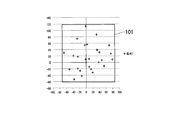
- FIG. 6A shows a distribution diagram in which the distribution of predicted colorimetric values in the L * a * b * color space is projected onto a two-dimensional a * b * coordinate system including the a * axis and the b * axis.
- FIG. 6B shows the dot area ratios of the CMY color component process inks of 0%, 50%, and 100% when the dot area ratio of the yellow-green special color ink is “40%”.
- a predicted colorimetric value obtained by multiplying any of the point area ratios is used.
- 6B shows a distribution diagram in which the distribution of predicted colorimetric values in the L * a * b * color space is projected onto the two-dimensional a * b * coordinate system, as in FIG. 6A.
- FIG. 6C shows the halftone dot area ratios of the process inks of the CMY color components when the halftone dot area ratio of the yellowish green special color ink is “70%”, respectively.
- a predicted colorimetric value obtained by multiplying any of the point area ratios is used.
- FIG. 6C shows a distribution diagram in which the distribution of predicted colorimetric values in the L * a * b * color space is projected onto the two-dimensional a * b * coordinate system.
- FIG. 6D shows the dot area ratio of each of the CMY color component process inks of 0%, 50%, and 100% when the dot area ratio of the yellow-green special color ink is “100%”. A predicted colorimetric value obtained by multiplying any of the point area ratios is used.
- FIG. 6D shows a distribution diagram in which the distribution of predicted colorimetric values in the L * a * b * color space is projected onto the two-dimensional a * b * coordinate system.
- the degree of variation in the predicted colorimetric value of the ink combination obtained by multiplying the halftone dot area ratio of the process ink in the process ink combination is detected for each spot ink combination of the control value of the spot color ink. be able to. In other words, the degree of influence of the change in the halftone dot area ratio in the yellow-green special color ink combination on the variation in the distribution of the colorimetric values for each process ink combination is detected.
- the influence degree forms the smallest rectangular inclusion region surrounding the distribution of the projected colorimetric values, and the length of the diagonal line of the inclusion region (101, 102, 103, 104). Based on.
- the adjustment coefficient calculation unit 18 determines that the dot area ratio of the spot color ink combination is “0%” based on the diagonal length of the inclusion region 101 when the dot area ratio of the spot color ink combination is “0%”.
- FIG. 7A to 7D are diagrams showing distributions of predicted colorimetric values by ink combinations of process ink combinations and spot color ink combinations using brown as the spot color ink.
- the brown color belongs to a relatively dark color among the special color inks.
- FIG. 7A shows the halftone dot area ratios of the process inks of CMY color components when the halftone dot area ratio of the brown spot color ink is “0%”, respectively. Predictive colorimetric values obtained by combining any of the area ratios are used.
- FIG. 7A shows a distribution diagram in which the distribution of predicted colorimetric values in the L * a * b * color space is projected onto the two-dimensional a * b * coordinate system.
- FIG. 7B shows the halftone dot area ratios of the process inks of the CMY color components when the halftone dot area ratio of the brown spot color ink is “40%”, respectively. Predictive colorimetric values obtained by combining any of the area ratios are used.
- FIG. 7B shows a distribution diagram in which the distribution of predicted colorimetric values in the L * a * b * color space is projected onto the two-dimensional a * b * coordinate system.
- FIG. 7C shows the halftone dot area ratios of the CMY color component process inks of 0%, 50%, and 100% when the halftone dot area ratio of the brown spot color ink is “70%”. Predictive colorimetric values obtained by combining any of the area ratios are used.
- FIG. 7C shows a distribution diagram in which the distribution of predicted colorimetric values in the L * a * b * color space is projected onto the two-dimensional a * b * coordinate system.
- FIG. 7D shows the halftone dot area ratios of the process inks of the CMY color components when the halftone dot area ratio of the brown spot color ink is “100%”, respectively. Predictive colorimetric values obtained by combining any of the area ratios are used.
- FIG. 7D shows a distribution diagram in which the distribution of predicted colorimetric values in the L * a * b * color space is projected onto the two-dimensional a * b * coordinate system.
- the degree of variation in the predicted colorimetric value of the ink combination is detected by multiplying the halftone dot area ratio of the process ink in each process ink combination for each spot color ink combination of the control value of the spot color ink. can do. That is, the degree of influence of the change in the halftone dot area ratio in the brown special color ink combination on the variation in the colorimetric value distribution for each process ink combination is detected.
- the influence degree is obtained based on the diagonal length of the inclusion area (201, 202, 203, 204) that forms a rectangular inclusion area surrounding the projected distribution.
- the adjustment coefficient calculation unit 18 determines that the dot area ratio of the spot color ink combination is “0%” based on the length of the diagonal line of the inclusion region 201 when the dot area ratio of the spot color ink combination is “0%”.
- the spot color ink is brown, the lengths of the diagonal lines of the inclusion area 201 of “40”, the inclusion area 202 of “40%”, the inclusion area 203 of “70%”, and the inclusion area 204 of “100%” are divided.
- An adjustment coefficient indicating the degree of influence on the variation in the colorimetric value due to the change in the dot area ratio of the process ink is obtained.
- FIGS. 8A and 8B are diagrams illustrating a configuration example of an adjustment coefficient table indicating adjustment coefficients for each control value of spot color ink.
- FIG. 8A shows that when the special color ink is yellowish green, the dot area ratio (special color ink control value) is 0%, 20%, 40%, 60%, 80%, as described in FIGS. 6A to 6D.
- An adjustment coefficient table when the adjustment coefficient when 100% is obtained is shown.
- the adjustment factors are 1.00, 0.98, 0.96 for each of the yellow-green halftone dot area ratios of 0%, 20%, 40%, 60%, 80%, and 100%. , 0.94, 0.91, and 0.88.
- the adjustment coefficient decreases as the control value of the special color ink increases, and the degree of influence (reflection degree) that the change in the control value of the process ink has on the variation of the ink combination decreases. That is, when the process ink is changed from the predicted colorimetric value to the measured colorimetric value, the difference colorimetric values ( ⁇ L 1 , ⁇ a 1 , ⁇ b 1 ) for changing the predicted colorimetric value are changed for each control value of the spot color ink. I understand that I need to
- FIG. 8B shows the dot area ratio (spot color ink control value) of 0%, 20%, 40%, 60%, and 80% as described in FIGS. 6A to 6D when the spot color ink is brown.
- the adjustment coefficient table when the adjustment coefficient when 100% is obtained is shown.
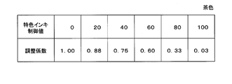
- the respective adjustment factors are 1.00, 0.88, 0.75 for brown dot area ratios of 0%, 20%, 40%, 60%, 80%, and 100%, respectively. 0.60, 0.33, and 0.03.
- the adjustment coefficient decreases as the control value of special color ink increases, and the degree of influence of variation in the control value of process ink on the variation in ink combination is reduced. I understand.
- the yellow-green halftone dot area ratio is 0%, 40%, 70%, or 100%
- the brown halftone dot area ratio is 0%, 40%, or 70.
- the adjustment coefficient calculation unit 18 obtains an adjustment value corresponding to the special color ink combination that is a combination of the control values of the special color ink for each special color ink combination that is a combination of the control values of the special color inks to be multiplied. Then, an adjustment coefficient table for each special color ink combination is generated. Then, the adjustment coefficient calculation unit 18 writes and stores the generated adjustment coefficient table in the adjustment coefficient storage unit 19 for each spot color ink or for each spot color ink multiplication. When the colorimetric value correction unit 13A corrects the predicted colorimetric value using the difference colorimetric value, the adjustment coefficient storage unit displays an adjustment coefficient corresponding to the spot color ink combination in the ink combination of the predicted colorimetric value to be corrected. Read out from 19 adjustment coefficient tables.
- the colorimetric value correction unit 13A a difference colorimetric values corresponding to the predicted colorimetric values to be corrected ( ⁇ L 1, ⁇ a 1, ⁇ b 1) reads, the difference colorimetric value ( ⁇ L 1, ⁇ a 1, ⁇ b 1 ) is multiplied by the adjustment coefficient to generate adjustment difference colorimetric values ( ⁇ L 1 ′, ⁇ a 1 ′, ⁇ b 1 ′).
- the colorimetric value correction unit 13A adds the generated adjustment difference colorimetric value to the predicted colorimetric value to be corrected.
- each of ⁇ L 1 ′, ⁇ a 1 ′, and ⁇ b 1 ′ is a multiplication result obtained by multiplying ⁇ L 1 , ⁇ a 1 , ⁇ b 1 by an adjustment coefficient.
- the colorimetric value correction unit 13A uses the corrected colorimetric values ( L1_n ′, a1_n ′, b1_n ′) obtained by addition to predictive colorimetry to be corrected in the reproduction color profile table of the reproduction color profile storage unit 14.
- the values (L 1 — n , a 1 — n , b 1 — n ) are overwritten, and the predicted colorimetric values are corrected.
- the adjustment coefficient calculation unit 18 when the adjustment coefficient calculation unit 18 obtains the adjustment coefficient, the predicted colorimetric value in the L * a * b * color space for each process ink combination in the dot area ratio of the special color ink is obtained.
- the diagonal length of the rectangular inclusion region that includes the distribution projected on the two-dimensional a * b * coordinate system is used.
- the adjustment coefficient calculation unit 18 may be configured to obtain the adjustment coefficient using the area of the rectangular inclusion region or the circumference of the inclusion region. Further, the adjustment coefficient calculation unit 18 uses the minimum rectangular parallelepiped shape including the predicted colorimetric value distribution in the L * a * b * color space as the inclusion region, and uses the volume, surface area, or diagonal length of the inclusion region. Thus, the adjustment coefficient may be obtained.
- the adjustment coefficient calculation unit 18 sets a minimum three-dimensional curved surface including all predicted colorimetric values distributed in the L * a * b * color space as an inclusion region, and the volume, surface area, or major axis length of the inclusion region. You may comprise so that an adjustment coefficient may be calculated
- the adjustment coefficient calculation unit 18 projects and projects a minimum three-dimensional curved surface including all predicted colorimetric values distributed in the L * a * b * color space onto the two-dimensional a * b * coordinate system.
- a two-dimensional shape may be used as an inclusion region, and the adjustment coefficient may be obtained using the area of the inclusion region, the circumference length, or the length of the major axis.
- the input / output unit 11 actually measures a color chart for each target process ink combination
- the measured measurement values are read as measurement colorimetric values.
- the input / output unit 11 does not need to read the colorimetric values.
- a limited (relatively large) number of color charts as an example, IT8 (about 1000 colors of a target, standard, standard, standard, standard, for color, communications, and control) specifications
- IT8 about 1000 colors of a target, standard, standard, standard, standard, for color, communications, and control
- CMYK profile is created by a general method.
- the input / output unit 11 may read the CMYK profile, read the colorimetric value corresponding to the process ink combination from the CMYK profile, and use the read colorimetric value as the measured colorimetric value.
- a program for realizing the functions of the reproduction color profile correction system 1 in FIG. 1 and the reproduction color profile correction system 1A in FIG. 5 is recorded on a computer-readable recording medium and recorded on the recording medium.
- the correction of the colorimetric values in the reproduction color profile may be controlled by causing the computer system to read and execute the program.
- the “computer system” here includes an OS and hardware such as peripheral devices.
- the “computer system” also includes a WWW system provided with a homepage providing environment (or display environment).
- the “computer-readable recording medium” refers to a storage device such as a flexible medium, a magneto-optical disk, a portable medium such as a ROM or a CD-ROM, and a hard disk incorporated in a computer system.
- the “computer-readable recording medium” refers to a volatile memory (RAM) in a computer system that becomes a server or a client when a program is transmitted via a network such as the Internet or a communication line such as a telephone line. In addition, those holding programs for a certain period of time are also included.
- RAM volatile memory
- the program may be transmitted from a computer system storing the program in a storage device or the like to another computer system via a transmission medium or by a transmission wave in the transmission medium.
- the “transmission medium” for transmitting the program refers to a medium having a function of transmitting information, such as a network (communication network) such as the Internet or a communication line (communication line) such as a telephone line.
- the program may realize a part of the functions described above.
- a so-called difference file (difference program) that can realize the above-described functions in combination with a program already recorded in the computer system may be used.
Landscapes
- Engineering & Computer Science (AREA)
- Multimedia (AREA)
- Signal Processing (AREA)
- Theoretical Computer Science (AREA)
- General Physics & Mathematics (AREA)
- Physics & Mathematics (AREA)
- General Engineering & Computer Science (AREA)
- Human Computer Interaction (AREA)
- Quality & Reliability (AREA)
- Facsimile Image Signal Circuits (AREA)
- Color Image Communication Systems (AREA)
- Color, Gradation (AREA)
- Image Processing (AREA)
Abstract
再現色プロファイルにおける、プロセスインキの制御値の組合せであるプロセスインキ組合せと特色インキの制御値の組合せである特色インキ組合せとからなるインキ組合せによる再現色の測色値を補正する再現色プロファイル補正システムであり、インキ組合せにおけるプロセスインキ組合せに対応して予測した再現色の測色値である予測測色値と、プロセスインキ組合せに対応するカラーチャートの再現色を測定した測色値である測定測色値との差分である差分測色値を算出する差分測色値算出部と、差分測色値によりインキ組合せにおける再現色の予測測色値を補正する測色値補正部とを備える。
Description
本発明は、特色DDCP用の再現色プロファイル補正装置、再現色プロファイル補正方法、再現色プロファイル補正プログラム、及び再現色プロファイル補正プログラムを含むコンピュータ可読媒体に関する。
本願は、2016年6月1日に、日本に出願された特願2016-110327号に基づき優先権を主張し、これらの内容をここに援用する。
本願は、2016年6月1日に、日本に出願された特願2016-110327号に基づき優先権を主張し、これらの内容をここに援用する。
一般に、プリンタや印刷機などの出力装置に対応させ、出力装置毎の色空間での色管理をするため、出力装置が出力する印刷物における色の再現色プロファイルが作成される(例えば、特許文献1及び特許文献2参照)。この再現色プロファイルの作成の際、予め決められた各インキの制御値の組み合わせからなるカラーチャートを、プロファイル生成対象の出力装置から出力させる。
そして、カラーチャートにおいて、インキの制御値の組合せ毎のチャートの各々を測色し、この測定した測色値である測定測色値とこの測色値に対応するインキの制御値の組み合わせとの対応関係を取得し、再現色プロファイルを作成する。
そして、カラーチャートにおいて、インキの制御値の組合せ毎のチャートの各々を測色し、この測定した測色値である測定測色値とこの測色値に対応するインキの制御値の組み合わせとの対応関係を取得し、再現色プロファイルを作成する。
通常、プロセスインキに対応した再現色プロファイルは、通常用いられるプロセスインキ、例えばC(Cyan)M(Magenta)Y(Yellow)K(Black)の色成分のインキの掛け合わせによる再現色を管理する。このプロセスインキに対応した再現色プロファイルは、予め各色成分のプロセスインキの制御値の組み合わせのカラーチャートが印刷され、測定測色値が測定されて生成されている。
一方、特色インキをプロセスインキと組み合わせて用いる場合、特色に関しては印刷物毎に用いる特色の色が決定される。このため、プロセスインキの組合わせに対して特色インキを組み合わせる場合、プロセスインキの組み合わせのみの場合のように、予めカラーチャートを印刷し、印刷されたカラーチャートから測定測色値を得ることができない。すなわち、プロセスインキのみの組合わせの場合と異なり、特色インキを組み合わせる場合には、実際に印刷されたカラーチャートから測定測色値を求めて再現色プロファイルを作成することが現実的に行えない。
したがって、プロセスインキと特色インキとを組み合わせて用いる場合、この組み合わせにおける再現色の測色値の予測を行い、予測結果の予測測色値が再現色プロファイルの生成に用いられる。この再現色の予測は、例えば、特色のベタの測定測色値、網点のドットゲインなどのパラメータを、色予測システムの再現色予測モデル(あるいは色予測モデル)に対して入力し、特色インキ同士、もしくはプロセスインキと特色インキとを組み合わせた再現色の予測測色値を求めている。
そして、色予測システムが予測した予測測色値に基づいて、プロセスインキと特色インキとの組み合わせによる印刷物に対応した再現色プロファイルが生成される。
そして、色予測システムが予測した予測測色値に基づいて、プロセスインキと特色インキとの組み合わせによる印刷物に対応した再現色プロファイルが生成される。
しかしながら、色予測システムは、プロセスインキのみの組合わせに対しても、プロセスインキのベタの測定測色値を用い、再現色予測モデルにより予測測色値を求める。この予測測色値は、限られた情報から再現色予測モデルにより求めるため、カラーチャートを実際に測定して得られる測定測色値とは一致しない場合がある。
すなわち、予測測色値から作成した再現色プロファイルは、カラーチャートから得た測定測色値から作成した再現色プロファイルに比較し、再現色の精度が低いことが考えられる。
このため、再現色プロファイルの精度を向上させるため、再現色予測モデルから得られたプロセスインキのみの組合わせの予測測色値を、すでにカラーチャートで測定した測定測色値と入れ替える処理が行われる。
すなわち、予測測色値から作成した再現色プロファイルは、カラーチャートから得た測定測色値から作成した再現色プロファイルに比較し、再現色の精度が低いことが考えられる。
このため、再現色プロファイルの精度を向上させるため、再現色予測モデルから得られたプロセスインキのみの組合わせの予測測色値を、すでにカラーチャートで測定した測定測色値と入れ替える処理が行われる。
このとき、プロセスインキと特色インキとを組み合わせた再現色の予測測色値は、測定測色値による補正を反映させることができず、再現色予測モデルにより予測された予測測色値のままとなる。
この結果、再現色予測モデルで予測した予測測色値と、カラーチャートから求めた測定測色値とが同一の再現色プロファイルにて混在するため、再現色プロファイルにおける測色値の整合性が取れない。すなわち、インキの組み合わせと測色値との対応関係において、特色インキとプロセスインキとの組合せによる再現色が、プロセスインキの測定測色値が反映されないため、プロセスインキのみの組合せのみの再現色と比較すると不自然な色となり整合性が取れない。
この結果、再現色予測モデルで予測した予測測色値と、カラーチャートから求めた測定測色値とが同一の再現色プロファイルにて混在するため、再現色プロファイルにおける測色値の整合性が取れない。すなわち、インキの組み合わせと測色値との対応関係において、特色インキとプロセスインキとの組合せによる再現色が、プロセスインキの測定測色値が反映されないため、プロセスインキのみの組合せのみの再現色と比較すると不自然な色となり整合性が取れない。
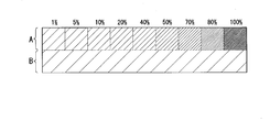
図9は、特色インキとプロセスインキとの再現色の比較を行う評価チャートを示す。図9においては、色成分C、色成分M及び色成分Yの各々のプロセスインキを、同一の制御値(平網、例えば網点面積率がC=M=Y=30%)の組合せで印刷した際の測色値を再現した画像を示す。図9におけるチャートの上半分の領域Aは、特色インキ(例えば、黄緑色、茶色など)を、順次、1%→5%→10%→20%→30%→40%→50%→70%→80%→100%と増加させて、プロセスインキの平網の組合せに含めた場合の測色値を再現している。領域Bは、プロセスインキの平網の組合せのままの測色値が再現されている。
図9に示したチャートに対してプロセスインキの測定測色値による補正を行った場合、領域Bは、プロセスインキの組合せのみであるため、測色値を予測測色値から測定測色値に補正することができ、プロセスインキの組合せにより再現される測色値を正確に表現する。
一方、領域Aは、プロセスインキと特色インキとの組合せによる再現色の測色値であるため、プロセスインキの測定測色値に対応した予測測色値のシミュレーションが行えず、元々の再現色予測モデルにより得られる予測測色値のままとなる。
一方、領域Aは、プロセスインキと特色インキとの組合せによる再現色の測色値であるため、プロセスインキの測定測色値に対応した予測測色値のシミュレーションが行えず、元々の再現色予測モデルにより得られる予測測色値のままとなる。
この結果、すでに述べたように、領域Aにおいて特色インキの制御値が低い場合、例えば1%の場合には、ほぼプロセスインキのみの組合せの再現色の測色値であって領域Bと同様の測色値である。しかしながら、領域Aがプロセスインキと特色インキとの組合せの再現色であるため、上記測定測色値に対応した補正がなされず、予測測色値のままのプロセスインキの組合せに対応している。このため、領域Aの制御値が1%の測色値と領域Bの測色値とは、ほぼ同様であるはずの測色値が異なり、比較すると不自然な再現色となる。
本発明は、このような状況に鑑みてなされたもので、プロセスインキの組合わせのみのカラーチャートから求めた測定測色値により、プロセスインキのみの場合とプロセスインキと特色インキとの組合せの場合との各々の間の再現色の整合性がとれた補正を、予測測色値から作成した再現色プロファイルに対して行うことが可能な再現色プロファイル補正装置、再現色プロファイル補正方法及びプログラムを提供する。
本発明の再現色プロファイル補正装置は、再現色プロファイルにおける、プロセスインキの制御値の組合せであるプロセスインキ組合せと特色インキの制御値の組合せである特色インキ組合せとからなるインキ組合せによる再現色の測色値を補正する再現色プロファイル補正装置であり、前記インキ組合せにおける前記プロセスインキ組合せに対応して予測した再現色の測色値である予測測色値と、前記プロセスインキ組合せに対応するカラーチャートの再現色を測定した測色値である測定測色値との差分である差分測色値を算出する差分測色値算出部と、前記差分測色値により前記インキ組合せにおける再現色の予測測色値を補正する測色値補正部とを備える。
本発明の再現色プロファイル補正装置は、前記インキ組合せにおいて、特色インキの網点面積率毎に、所定の色空間に分布する、前記プロセスインキ組合せのプロセスインキそれぞれの制御値が異なる組合せの測色値を包含する包含領域を抽出する包含領域抽出部と、前記特色インキの制御値毎に、前記差分測色値に乗ずる調整係数を、前記包含領域の大きさに基づいて算出する調整係数算出部とを備える。
本発明の再現色プロファイル補正装置は、前記測色値補正部が、前記特色インキ組合せに対応した前記調整係数を、前記差分測色値に対して乗じて、前記特色インキ組合せを有する前記特色インキの前記予測測色値を補正する。
本発明の再現色プロファイル補正装置は、調整係数算出部が、前記包含領域の大きさが前記特色インキの網点面積率が「0」の場合における、所定の色空間に分布する、プロセスインキそれぞれの網点面積率が異なる組合せの測色値を包含する前記包含領域の大きさを基準値とし、前記基準値により前記特色インキの網点面積率毎の包含領域の大きさを除算して前記調整係数を算出する。
本発明の再現色プロファイル補正装置は、前記包含領域の大きさが、前記所定の色空間における前記包含領域の体積である。
本発明の再現色プロファイル補正装置は、前記包含領域の大きさが、前記所定の色空間における前記包含領域を2次元平面に投影した際の投影面の面積である。
本発明の再現色プロファイル補正装置は、前記包含領域の大きさが、前記所定の色空間における前記測色値の分布を包含する直方体の対角線の長さである。
本発明の再現色プロファイル補正方法は、再現色プロファイルにおける、プロセスインキの制御値の組合せであるプロセスインキ組合せと特色インキの制御値の組合せである特色インキ組合せとからなるインキ組合せによる再現色の測色値を補正する再現色プロファイル補正方法であり、差分測色値算出部が、前記インキ組合せにおける前記プロセスインキ組合せに対応して予測した再現色の測色値である予測測色値と、前記プロセスインキ組合せに対応するカラーチャートの再現色を測定した測色値である測定測色値との差分である差分測色値を算出する差分測色値算出過程と、測色値補正部が、前記差分測色値により前記インキ組合せにおける再現色の予測測色値を補正する測色値補正過程とを含む。
本発明のプログラムは、再現色プロファイルにおける、プロセスインキの制御値の組合せであるプロセスインキ組合せと特色インキの制御値の組合せである特色インキ組合せとからなるインキ組合せによる再現色の測色値を補正する再現色プロファイル補正システムとして、コンピュータを機能させる再現色プロファイル補正プログラムであり、前記インキ組合せにおけるプロセスインキ組合せに対応して予測した再現色の測色値である予測測色値と、前記プロセスインキ組合せに対応するカラーチャートの再現色を測定した測色値である測定測色値との差分である差分測色値を算出し、前記差分測色値により前記インキ組合せにおける再現色の予測測色値を補正する、再現色プロファイル補正方法を実行するようにコンピュータを動作させる再現色プロファイル補正プログラムである。
本発明のコンピュータ可読媒体は、再現色プロファイルにおける、プロセスインキの制御値の組合せであるプロセスインキ組合せと特色インキの制御値の組合せである特色インキ組合せとからなるインキ組合せによる再現色の測色値を補正する再現色プロファイル補正システムとして、コンピュータを機能させ、前記インキ組合せにおけるプロセスインキ組合せに対応して予測した再現色の測色値である予測測色値と、前記プロセスインキ組合せに対応するカラーチャートの再現色を測定した測色値である測定測色値との差分である差分測色値を算出し、前記差分測色値により前記インキ組合せにおける再現色の予測測色値を補正する、再現色プロファイル補正方法を実行するようにコンピュータを動作させる、再現色プロファイル補正プログラムを含む。
本発明のコンピュータ可読媒体は、再現色プロファイルにおける、プロセスインキの制御値の組合せであるプロセスインキ組合せと特色インキの制御値の組合せである特色インキ組合せとからなるインキ組合せによる再現色の測色値を補正する再現色プロファイル補正システムとして、コンピュータを機能させ、前記インキ組合せにおけるプロセスインキ組合せに対応して予測した再現色の測色値である予測測色値と、前記プロセスインキ組合せに対応するカラーチャートの再現色を測定した測色値である測定測色値との差分である差分測色値を算出し、前記差分測色値により前記インキ組合せにおける再現色の予測測色値を補正する、再現色プロファイル補正方法を実行するようにコンピュータを動作させる、再現色プロファイル補正プログラムを含む。
以上説明したように、本発明によれば、プロセスインキの組合わせのみのカラーチャートから求めた測定測色値により、プロセスインキのみの場合とプロセスインキと特色インキとの組合せの場合との各々の間の再現色の整合性がとれた補正を、予測測色値から作成した再現色プロファイルに対して行うことが可能な再現色プロファイル補正装置、再現色プロファイル補正方法及びプログラムを提供することが可能となる。
本発明の実施形態において、再現色プロファイルを構成する色予測テーブルには、プロセスインキ及び特色インキ各々のチャンネルの各々のインキの階調を制御する制御値(例えば、網点面積率など)を一定の間隔で区切った格子点上に、この格子点に対応する組合せによる印刷において再現される測色値が示されている。以下、プロセスインキ組合せは、プロセスインキにおける各色成分(CMYK)のインキの制御値の組合せを示している。特色インキ組合せは、1個あるいは2個以上の複数の特色インキの制御値の組合せを示している。インキ組合せは、プロセスインキ組合せと特色インキ組合せとの組合せを示している。
ここで、プロセスインキ組合せの測色値は、多くの制御値の組合せがカラーチャートとして印刷され、それぞれの組合せに対応するカラーチャート(以下、チャートとも言う)の測色値が測定測色値として測定されている。しかしながら、特色インキ組合せが含まれる場合、プロセスインキ組合せと特色インキ組合せからなるインキ組合せで印刷されたカラーチャートは存在しない。このため、すでに説明したように、特色インキ組合せが含まれる場合には、一般的な再現色予測モデルを用いたシミュレーションにより、プロセスインキ及び特色インキ各々のチャンネルの各々の制御値の格子点に対応するインキ組合せによる印刷で再現される予測測色値を求める。
<第1の実施形態>
以下、本発明の第1の実施形態について、図面を参照して説明する。
図1は、本発明の第1の実施形態による再現色プロファイル補正システム(再現色プロファイル補正装置)1の構成例を示すブロック図である。
図1において、再現色プロファイル補正システム1は、入出力部11、差分測色値算出部12、測色値補正部13、再現色プロファイル記憶部14、測定測色値記憶部15及び差分測色値記憶部16の各々を備えている。以下、本実施形態においては、測色値を示す空間をL*a*b*色空間として説明する。
以下、本発明の第1の実施形態について、図面を参照して説明する。
図1は、本発明の第1の実施形態による再現色プロファイル補正システム(再現色プロファイル補正装置)1の構成例を示すブロック図である。
図1において、再現色プロファイル補正システム1は、入出力部11、差分測色値算出部12、測色値補正部13、再現色プロファイル記憶部14、測定測色値記憶部15及び差分測色値記憶部16の各々を備えている。以下、本実施形態においては、測色値を示す空間をL*a*b*色空間として説明する。
入出力部11は、外部装置から供給される予測測色値により求められた、再現色プロファイルを読み込み、再現色プロファイル記憶部14に対して書き込んで記憶させる。本実施形態において、再現色プロファイルは、例えば、再現色予測モデルによるシミュレーションにより求めた予測測色値により生成されており、CMYKによるプロセスインキ組合せ及び特色インキの組合せからなるインキ組合せと、このインキ組合わせによる再現色の予測測色値とが対応したテーブル構成(再現色プロファイルテーブル)となっている。再現色予測モデルは、本実施形態において、上記インキ組合せの予測測色値をシミュレーションにより得られるのであれば、いずれでも良い。
また、入出力部11は、外部装置から供給される測定測色値(後述する測定測色値テーブル)を読み込み、測定測色値記憶部15に対して書き込んで記憶させる。本実施形態における測定測色値は、CMYKの各々のプロセスインキの制御値のプロセスインキ組合せを実際に印刷した再現色のチャートから、プロセスインキ組合せ毎に測定した測色値である。この測定測色値は、CMYKの各々の制御値の組合せとこの組合せのチャートから測定した測定測色値とが対応して記載された測定測色値テーブルとして供給される。また、入出力部11は、外部から供給される制御指令を、再現色プロファイル補正システム1の各部に出力する。
差分測色値算出部12は、測定測色値記憶部15の測定測色値テーブルから、順次、測定測色値とこの測定測色値に対応するプロセスインキ組合せ(プロセスインキ各々の制御値の組合せ)との各々を読み出す。そして、差分測色値算出部12は、このプロセスインキ組合せと同一のプロセスインキ組合せのみのインキ組合せを、再現色プロファイル記憶部14の再現色プロファイルテーブルから検索する。ここで、プロセスインキ組合わせのみのインキ組合わせとは、特色インキの制御値が「0」であるインキ組合わせを示している。差分測色値算出部12は、検索されたプロセスインキ組合せの予測測色値を上記再現色プロファイルテーブルから読み出す。差分測色値算出部12は、以下に示すように、測定測色値から予測測色値を減算し、測定測色値と予測測色値との差分である差分測色値を求める。
差分予測値(ΔL1,Δa1,Δb1)
=測定測色値(L1,a1,b1)-予測測色値(L1_0,a1_0,b1_0)
ここで、ΔL1=L1-L1_0、Δa=a1-a1_0、Δb=b1-b1_0である。
差分測色値算出部12は、求めた差分測色値を、測定測色値及び予測測色値の各々とともに、プロセスインキ組合せに対応させ、差分測色値記憶部16の差分測色値テーブルに書き込んで記憶させる。
=測定測色値(L1,a1,b1)-予測測色値(L1_0,a1_0,b1_0)
ここで、ΔL1=L1-L1_0、Δa=a1-a1_0、Δb=b1-b1_0である。
差分測色値算出部12は、求めた差分測色値を、測定測色値及び予測測色値の各々とともに、プロセスインキ組合せに対応させ、差分測色値記憶部16の差分測色値テーブルに書き込んで記憶させる。
図2は、差分測色値記憶部16に記憶されている差分測色値テーブルの構成例を示す図である。差分測色値テーブルは、プロセスインキ組合せと、このプロセスインキ組合せに対応する測定測色値、予測測色値及び差分測色値の各々とが対として記憶されている。
すなわち、プロセスインキ組合せ、すなわちCMYKの各々のプロセスインキの制御値の組合せ毎に、測定測色値と予測測色値との差分である差分測色値が求められて記憶されている。
すなわち、プロセスインキ組合せ、すなわちCMYKの各々のプロセスインキの制御値の組合せ毎に、測定測色値と予測測色値との差分である差分測色値が求められて記憶されている。
図1に戻り、測色値補正部13は、差分測色値記憶部16の差分測色値テーブルから、順次、プロセスインキ組合せ及びこのプロセスインキ組合せに対応する差分測色値(L1,a1,b1)の各々を読み出す。そして、測色値補正部13は、読み出したプロセスインキ組合せと同一のプロセスインキの組合せを有するインキ組合せを、再現色プロファイル記憶部14の再現色プロファイルテーブルから検出する。測色値補正部13は、検出されたインキ組合せ各々の予測測色値(L1_n,a1_n,b1_n)を読み出し、読み出した予測測色値(L1_n,a1_n,b1_n)に対して、プロセスインキ組合せの差分測色値を加算する。測色値補正部13は、加算して求めた補正測色値(L1_n’,a1_n’,b1_n’)を、再現色プロファイルテーブルの加算対象の予測測色値(L1_n,a1_n,b1_n)に対して上書きし(変更し)、予測測色値の補正を行う。ここで、L1_n’=L1_n+ΔL1、a1_n’=a1_n+Δa1、b1_n’=b1_n+Δb1である。また、nは、1~mの整数であり、mは、同一のプロセスインキ組合せを有するインキ組合せの数である。
図3は、本実施形態におけるL*a*b*色空間での測色値の補正を説明する図である。図3において、測定測色値(L1,a1,b1)と予測測色値(L1_0,a1_0,b1_0)との差分である差分測色値(ΔL1,Δa1,Δb1)が求められる。この差分測色値(ΔL1,Δa1,Δb1)は、L*a*b*色空間における予測測色値(L1_0,a1_0,b1_0)の座標点と、測定測色値(L1,a1,b1)の座標点との差分ベクトルを表す。ここで、予測測色値(L1_0,a1_0,b1_0)は、インキ組合せにおける特色インキ組合せの特色インキの制御値が「0」である予測測色値を示している。すなわち、予測測色値(L1_0,a1_0,b1_0)は、カラーチャートで測定される測定測色値(L1,a1,b1)のプロセスインキ組合せと同一のインキ組合せ(プロセスインキ組合せのみ)を有している。
これにより、測色値補正部13は、上記差分測色値(ΔL1,Δa1,Δb1)を用いて、プロセスインキ組合せと同一のプロセスインキ組合せを有するインキ組合せの予測測色値を補正測色値に補正する。すなわち、測色値補正部13は、プロセスインキ組合せが同一であれば、特色インキの制御値が「0」でないインキ組合せ各々の予測測色値も含めて、差分測色値(ΔL1,Δa1,Δb1)により補正する。
図4は、第1の実施形態における再現色プロファイルの補正の動作例を示すフローチャートである。
ステップS11:
入出力部11は、外部から供給される再現色プロファイル(再現色プロファイルテーブル)を、再現色プロファイル記憶部14に対して書き込んで記憶させる。
ステップS11:
入出力部11は、外部から供給される再現色プロファイル(再現色プロファイルテーブル)を、再現色プロファイル記憶部14に対して書き込んで記憶させる。
ステップS12:
入出力部11は、外部から供給される、カラーチャートにおけるプロセスインキ組合せ毎のチャートの再現色を測定した測定測色値の各々を、測定測色値記憶部15に書き込んで記憶させる。ここで、入出力部11は、再現色を再現するプロセスインキ組合せと、このプロセスインキ組合せによる再現色の測定測色値とを対とした測定測色値テーブルを、測定測色値記憶部15に書き込んで記憶させる。
入出力部11は、外部から供給される、カラーチャートにおけるプロセスインキ組合せ毎のチャートの再現色を測定した測定測色値の各々を、測定測色値記憶部15に書き込んで記憶させる。ここで、入出力部11は、再現色を再現するプロセスインキ組合せと、このプロセスインキ組合せによる再現色の測定測色値とを対とした測定測色値テーブルを、測定測色値記憶部15に書き込んで記憶させる。
ステップS13:
差分測色値算出部12は、測定測色値記憶部15の測定測色値テーブルから、記載されている順番にプロセスインキ組合せと、このプロセスインキ組合せの再現色の測定測色値(L1,a1,b1)との各々を読み出す。
そして、差分測色値算出部12は、上記プロセスインキ組合せと同一のプロセスインキ組合せを有する、特色インキ組合せの制御値が「0」であるインキ組合せを、再現色プロファイル記憶部14の再現色プロファイルテーブルにおいて検出する。
差分測色値算出部12は、測定測色値記憶部15の測定測色値テーブルから、記載されている順番にプロセスインキ組合せと、このプロセスインキ組合せの再現色の測定測色値(L1,a1,b1)との各々を読み出す。
そして、差分測色値算出部12は、上記プロセスインキ組合せと同一のプロセスインキ組合せを有する、特色インキ組合せの制御値が「0」であるインキ組合せを、再現色プロファイル記憶部14の再現色プロファイルテーブルにおいて検出する。
差分測色値算出部12は、検出したインキ組合せに対応して記憶されている予測測色値(L1_0,a1_0,b1_0)を、測定測色値テーブルから読み出す。
差分測色値算出部12は、測定測色値(L1,a1,b1)から予測測色値(L1_0,a1_0,b1_0)を減算し、差分測色値(ΔL1,Δa1,Δb1)を算出する。
そして、差分測色値算出部12は、差分測色値(ΔL1,Δa1,Δb1)を、プロセスインキ組合せと、測定測色値(L1,a1,b1)と、予測測色値(L1_0,a1_0,b1_0)との各々と対応させ、差分測色値記憶部16の差分測色値テーブルに書き込んで記憶させる。
差分測色値算出部12は、測定測色値(L1,a1,b1)から予測測色値(L1_0,a1_0,b1_0)を減算し、差分測色値(ΔL1,Δa1,Δb1)を算出する。
そして、差分測色値算出部12は、差分測色値(ΔL1,Δa1,Δb1)を、プロセスインキ組合せと、測定測色値(L1,a1,b1)と、予測測色値(L1_0,a1_0,b1_0)との各々と対応させ、差分測色値記憶部16の差分測色値テーブルに書き込んで記憶させる。
ステップS14:
差分測色値算出部12は、測定測色値記憶部15の測定測色値テーブルに記載されている全てのプロセスインキ組合せに対応する差分測色値の算出が終了したか否かの判定を行う。このとき、差分測色値算出部12は、測定測色値テーブルに記載されている全てのプロセスインキ組合せに対応する差分測色値の算出が終了した場合、処理をステップS15へ進める。一方、差分測色値算出部12は、測定測色値テーブルに記載されている全てのプロセスインキ組合せに対応する差分測色値の算出が終了していない場合、処理をステップS13へ進める。
差分測色値算出部12は、測定測色値記憶部15の測定測色値テーブルに記載されている全てのプロセスインキ組合せに対応する差分測色値の算出が終了したか否かの判定を行う。このとき、差分測色値算出部12は、測定測色値テーブルに記載されている全てのプロセスインキ組合せに対応する差分測色値の算出が終了した場合、処理をステップS15へ進める。一方、差分測色値算出部12は、測定測色値テーブルに記載されている全てのプロセスインキ組合せに対応する差分測色値の算出が終了していない場合、処理をステップS13へ進める。
ステップS15:
測色値補正部13は、差分測色値記憶部16の差分測色値テーブルから、記載された順番に、プロセスインキ組合せと、このプロセスインキ組合せに対応する差分測色値との各々を読み出す。
測色値補正部13は、差分測色値記憶部16の差分測色値テーブルから、記載された順番に、プロセスインキ組合せと、このプロセスインキ組合せに対応する差分測色値との各々を読み出す。
ステップS16:
次に、測色値補正部13は、対象プロセスインキ組合せと同一のプロセスインキ組合せを有するインキ組合せを、再現色プロファイル記憶部14の再現色プロファイルテーブルから検出する。ここで、対象プロセスインキ組合せは、差分測色値記憶部16の差分測色値テーブルから、記載された順番に読み出したプロセスインキ組合せを指している。
測色値補正部13は、対象プロセスインキ組合せと同一のプロセスインキ組合せを有するインキ組合せを、再現色プロファイルテーブルに記載された順番に検出する。
次に、測色値補正部13は、対象プロセスインキ組合せと同一のプロセスインキ組合せを有するインキ組合せを、再現色プロファイル記憶部14の再現色プロファイルテーブルから検出する。ここで、対象プロセスインキ組合せは、差分測色値記憶部16の差分測色値テーブルから、記載された順番に読み出したプロセスインキ組合せを指している。
測色値補正部13は、対象プロセスインキ組合せと同一のプロセスインキ組合せを有するインキ組合せを、再現色プロファイルテーブルに記載された順番に検出する。
そして、測色値補正部13は、検出されたインキ組合せに対応する予測測色値(L1_n,a1_n,b1_n)を、再現色プロファイルテーブルから読み出す。
測色値補正部13は、読み出した予測測色値(L1_n,a1_n,b1_n)に対して、差分測色値(ΔL1,Δa1,Δb1)を加算し、補正測色値(L1_n’,a1_n’,b1_n’)を算出する。ここで、測色値補正部13は、補正測色値(L1_n’,a1_n’,b1_n’)を、再現色プロファイルテーブルの予測測色値(L1_n,a1_n,b1_n)に上書きすることにより、再現色プロファイルテーブルの補正を行う。
測色値補正部13は、読み出した予測測色値(L1_n,a1_n,b1_n)に対して、差分測色値(ΔL1,Δa1,Δb1)を加算し、補正測色値(L1_n’,a1_n’,b1_n’)を算出する。ここで、測色値補正部13は、補正測色値(L1_n’,a1_n’,b1_n’)を、再現色プロファイルテーブルの予測測色値(L1_n,a1_n,b1_n)に上書きすることにより、再現色プロファイルテーブルの補正を行う。
ステップS17:
測色値補正部13は、再現色プロファイルテーブルにおいて、対象プロセスインキ組合せと同一のプロセスインキ組合せを有するインキ組合せの全ての予測測色値の補正が終了したか否かの判定を行う。
このとき、測色値補正部13は、対象プロセスインキ組合せと同一のプロセスインキ組合せを有するインキ組合せの全ての予測測色値の補正が終了した場合、処理をステップS18へ進める。一方、測色値補正部13は、対象プロセスインキ組合せと同一のプロセスインキ組合せを有するインキ組合せの全ての予測測色値の補正が終了していない場合、処理をステップS16へ進め、再現色プロファイルテーブルにおける残りのインキ組み合わせの予測測色値の補正を行う。
測色値補正部13は、再現色プロファイルテーブルにおいて、対象プロセスインキ組合せと同一のプロセスインキ組合せを有するインキ組合せの全ての予測測色値の補正が終了したか否かの判定を行う。
このとき、測色値補正部13は、対象プロセスインキ組合せと同一のプロセスインキ組合せを有するインキ組合せの全ての予測測色値の補正が終了した場合、処理をステップS18へ進める。一方、測色値補正部13は、対象プロセスインキ組合せと同一のプロセスインキ組合せを有するインキ組合せの全ての予測測色値の補正が終了していない場合、処理をステップS16へ進め、再現色プロファイルテーブルにおける残りのインキ組み合わせの予測測色値の補正を行う。
ステップS18:
測色値補正部13は、差分測色値記憶部16の差分測色値テーブルにおける全てのプロセスインキ組合せの差分測色値の読み出しが終了したか否かの判定を行う。
そして、測色値補正部13は、差分測色値テーブルにおける全てのプロセスインキ組合せの差分測色値の読み出しが終了した場合、再現色プロファイルの補正処理を終了する。一方、測色値補正部13は、差分測色値テーブルにおける全てのプロセスインキ組合せの差分測色値の読み出しが終了していない場合、処理をステップS15へ進め、次のプロセスインキ組合せの差分測色値を用い、予測測色値の補正の処理を行う。
測色値補正部13は、差分測色値記憶部16の差分測色値テーブルにおける全てのプロセスインキ組合せの差分測色値の読み出しが終了したか否かの判定を行う。
そして、測色値補正部13は、差分測色値テーブルにおける全てのプロセスインキ組合せの差分測色値の読み出しが終了した場合、再現色プロファイルの補正処理を終了する。一方、測色値補正部13は、差分測色値テーブルにおける全てのプロセスインキ組合せの差分測色値の読み出しが終了していない場合、処理をステップS15へ進め、次のプロセスインキ組合せの差分測色値を用い、予測測色値の補正の処理を行う。
上述したように、本実施形態においては、プロセスインキ組合せにより再現したカラーチャートの再現色を測定した測定測色値と、このプロセスインキ組合せと同一のプロセスインキ組合せを有し、かつ特色インキの制御値が「0」であるインキ組合せの予測測色値とから、差分測色値を求める。本実施形態によれば、求めた差分測色値により、この測定測色値のプロセスインキ組合せと同一のプロセスインキ組合せを有するインキ組合せの予測測色値を補正するため、プロセスインキ組合せの測定測色値によるインキ組合せにおける予測測色値の補正を、制御値が「0」でない特色インキ組合せを含むインキ組合せにも適用させることができ、プロセスインキのみの場合とプロセスインキと特色インキとの組み合わせの場合とで整合性がとれた補正を行うことが可能となる。
<第2の実施形態>
以下、本発明の第2の実施形態について、図面を参照して説明する。
図5は、本発明の第2の実施形態による再現色プロファイル補正システム(再現色プロファイル補正装置)1Aの構成例を示すブロック図である。
図5において、再現色プロファイル補正システム1は、入出力部11、差分測色値算出部12、測色値補正部13A、再現色プロファイル記憶部14、測定測色値記憶部15、差分測色値記憶部16、包含領域抽出部17、調整係数算出部18及び調整係数記憶部19の各々を備えている。第1の実施形態と同様の構成については同一の符号を付し、その説明を省略する。以下、第1の実施形態と異なる構成及び動作について説明する。
また、本実施形態においては、第1の実施形態と同様に、測色値を示す空間をL*a*b*色空間として説明する。
以下、本発明の第2の実施形態について、図面を参照して説明する。
図5は、本発明の第2の実施形態による再現色プロファイル補正システム(再現色プロファイル補正装置)1Aの構成例を示すブロック図である。
図5において、再現色プロファイル補正システム1は、入出力部11、差分測色値算出部12、測色値補正部13A、再現色プロファイル記憶部14、測定測色値記憶部15、差分測色値記憶部16、包含領域抽出部17、調整係数算出部18及び調整係数記憶部19の各々を備えている。第1の実施形態と同様の構成については同一の符号を付し、その説明を省略する。以下、第1の実施形態と異なる構成及び動作について説明する。
また、本実施形態においては、第1の実施形態と同様に、測色値を示す空間をL*a*b*色空間として説明する。
包含領域抽出部17は、インキ組合せにおける特色インキ組合せ毎に、L*a*b*色空間において、プロセスインキ組合せによる測色値の座標値の分布を生成する。本実施形態において、特色インキ組合せは、例えば1種類の特色インキを用いており、この1種類の特色インキの異なる制御値となる。制御値としては網点面積率を用いており、特色インキ組合わせとしては、1種類の特色インキの網点面積率を0%、40%、70%及び100%の各々とした組合せである。包含領域抽出部17は、再現色プロファイル記憶部14の再現色プロファイルテーブルから、特色インキ組合せが同一のインキ組合せを抽出し、抽出した特色インキ組合わせの測色値を、L*a*b*色空間に対して分布させる。本実施形態においては、特色インキ組合わせが同一である全てのインキ組合せを抽出するのではなく、このインキ組合せにおけるプロセスインキ組合せにおける色成分CMYの各々のプロセスインキの網点面積率が0%、50%、100%のいずれかである組合せを抽出して分布させる。
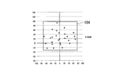
図6A~図6Dは、プロセスインキ組合せと特色インキとして黄緑色を用いた特色インキ組合せとのインキ組合せによる予測測色値の分布を示す図である。ここで、黄緑色は、特色インキのなかで比較的に薄い分類の色に属している。
図6Aは、黄緑色の特色インキの網点面積率が「0%」の場合において、CMYの色成分のプロセスインキの各々の網点面積率を、それぞれ0%、50%、100%の網点面積率のいずれかを掛け合わせて組み合わせた予測測色値が用いられている。そして、図6Aは、L*a*b*色空間における予測測色値の分布を、a*軸及びb*軸からなる2次元a*b*座標系に投影した分布図を示している。
図6Aは、黄緑色の特色インキの網点面積率が「0%」の場合において、CMYの色成分のプロセスインキの各々の網点面積率を、それぞれ0%、50%、100%の網点面積率のいずれかを掛け合わせて組み合わせた予測測色値が用いられている。そして、図6Aは、L*a*b*色空間における予測測色値の分布を、a*軸及びb*軸からなる2次元a*b*座標系に投影した分布図を示している。
図6Bは、黄緑色の特色インキの網点面積率が「40%」の場合において、CMYの色成分のプロセスインキの各々の網点面積率を、それぞれ0%、50%、100%の網点面積率のいずれかを掛け合わせて組み合わせた予測測色値が用いられている。そして、図6Bは、図6Aと同様に、L*a*b*色空間における予測測色値の分布を、2次元a*b*座標系に投影した分布図を示している。
図6Cは、黄緑色の特色インキの網点面積率が「70%」の場合において、CMYの色成分のプロセスインキの各々の網点面積率を、それぞれ0%、50%、100%の網点面積率のいずれかを掛け合わせて組み合わせた予測測色値が用いられている。そして、図6Cは、L*a*b*色空間における予測測色値の分布を、2次元a*b*座標系に投影した分布図を示している。
図6Dは、黄緑色の特色インキの網点面積率が「100%」の場合において、CMYの色成分のプロセスインキの各々の網点面積率を、それぞれ0%、50%、100%の網点面積率のいずれかを掛け合わせて組み合わせた予測測色値が用いられている。そして、図6Dは、L*a*b*色空間における予測測色値の分布を、2次元a*b*座標系に投影した分布図を示している。
図6A~図6Dの各々により、特色インキの制御値の特色インキ組合せ毎に、プロセスインキ組合せにおけるプロセスインキの網点面積率の掛け合わせによるインキ組合せの予測測色値のバラツキの度合いを検出することができる。すなわち、黄緑色の特色インキ組合せにおける網点面積率の変化が、プロセスインキ組合せ毎の測色値の分布のバラツキの大きさに対して与える影響度合いを検出する。
図6A~図6Dにおいて、上記影響度合いは、投影された測色値の分布を囲む最小の矩形状の包含領域を形成し、この包含領域(101、102、103、104)の対角線の長さに基づいて求められる。
本実施形態において、調整係数算出部18は、特色インキ組合せの網点面積率が「0%」の場合の包含領域101の対角線の長さにより、特色インキ組合せの網点面積率が「0%」の包含領域101、「40%」の包含領域102、「70%」の包含領域103、「100%」の包含領域104それぞれの対角線の長さを除算して、特色インキが黄緑色の場合における特色インキの網点面積率の変化によるプロセスインキ組合わせ毎の測色値の分布のバラツキに対する影響度合いを示す調整係数を求める。
本実施形態において、調整係数算出部18は、特色インキ組合せの網点面積率が「0%」の場合の包含領域101の対角線の長さにより、特色インキ組合せの網点面積率が「0%」の包含領域101、「40%」の包含領域102、「70%」の包含領域103、「100%」の包含領域104それぞれの対角線の長さを除算して、特色インキが黄緑色の場合における特色インキの網点面積率の変化によるプロセスインキ組合わせ毎の測色値の分布のバラツキに対する影響度合いを示す調整係数を求める。
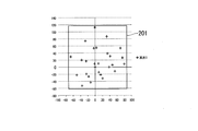
図7A~図7Dは、プロセスインキ組合せと特色インキとして茶色を用いた特色インキ組合せとのインキ組合せによる予測測色値の分布を示す図である。ここで、茶色は、特色インキのなかで比較的に濃い分類の色に属している。
図7Aは、茶色の特色インキの網点面積率が「0%」の場合において、CMYの色成分のプロセスインキの各々の網点面積率を、それぞれ0%、50%、100%の網点面積率のいずれかを掛け合わせて組み合わせた予測測色値が用いられている。そして、図7Aは、L*a*b*色空間における予測測色値の分布を、2次元a*b*座標系に投影した分布図を示している。
図7Aは、茶色の特色インキの網点面積率が「0%」の場合において、CMYの色成分のプロセスインキの各々の網点面積率を、それぞれ0%、50%、100%の網点面積率のいずれかを掛け合わせて組み合わせた予測測色値が用いられている。そして、図7Aは、L*a*b*色空間における予測測色値の分布を、2次元a*b*座標系に投影した分布図を示している。
図7Bは、茶色の特色インキの網点面積率が「40%」の場合において、CMYの色成分のプロセスインキの各々の網点面積率を、それぞれ0%、50%、100%の網点面積率のいずれかを掛け合わせて組み合わせた予測測色値が用いられている。そして、図7Bは、L*a*b*色空間における予測測色値の分布を、2次元a*b*座標系に投影した分布図を示している。
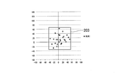
図7Cは、茶色の特色インキの網点面積率が「70%」の場合において、CMYの色成分のプロセスインキの各々の網点面積率を、それぞれ0%、50%、100%の網点面積率のいずれかを掛け合わせて組み合わせた予測測色値が用いられている。そして、図7Cは、L*a*b*色空間における予測測色値の分布を、2次元a*b*座標系に投影した分布図を示している。
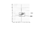
図7Dは、茶色の特色インキの網点面積率が「100%」の場合において、CMYの色成分のプロセスインキの各々の網点面積率を、それぞれ0%、50%、100%の網点面積率のいずれかを掛け合わせて組み合わせた予測測色値が用いられている。そして、図7Dは、L*a*b*色空間における予測測色値の分布を、2次元a*b*座標系に投影した分布図を示している。
上記図7A~図7Dの各々により、特色インキの制御値の特色インキ組合せ毎に、プロセスインキ組合せにおけるプロセスインキの網点面積率の掛け合わせによるインキ組合せの予測測色値のバラツキの度合いを検出することができる。すなわち、茶色の特色インキ組合せにおける網点面積率の変化が、プロセスインキ組合せ毎の測色値の分布のバラツキの大きさに対して与える影響度合いを検出する。
図7A~図7Dにおいて、上記影響度合いは、投影された分布を囲む矩形状の包含領域を形成し、この包含領域(201、202、203、204)の対角線の長さに基づいて求められる。
本実施形態において、調整係数算出部18は、特色インキ組合せの網点面積率が「0%」の場合の包含領域201の対角線の長さにより、特色インキ組合せの網点面積率が「0%」の包含領域201、「40%」の包含領域202、「70%」の包含領域203、「100%」の包含領域204それぞれの対角線の長さを除算して、特色インキが茶色の場合におけるプロセスインキの網点面積率の変化による測色値のバラツキに対する影響度合いを示す調整係数を求める。
本実施形態において、調整係数算出部18は、特色インキ組合せの網点面積率が「0%」の場合の包含領域201の対角線の長さにより、特色インキ組合せの網点面積率が「0%」の包含領域201、「40%」の包含領域202、「70%」の包含領域203、「100%」の包含領域204それぞれの対角線の長さを除算して、特色インキが茶色の場合におけるプロセスインキの網点面積率の変化による測色値のバラツキに対する影響度合いを示す調整係数を求める。
図8A及び図8Bは、特色インキの制御値毎の調整係数を示す調整係数テーブルの構成例を示す図である。図8Aは、特色インキが黄緑色の際に、図6A~図6Dで述べたように、網点面積率(特色インキ制御値)を0%、20%、40%、60%、80%、100%としたときの調整係数を求めた場合の調整係数テーブルを示している。図8Aにおいては、黄緑色の網点面積率0%、20%、40%、60%、80%、100%の各々に対し、それぞれの調整係数が1.00、0.98、0.96、0.94、0.91、0.88である。特色インキの制御値が増加するに従って調整係数が低くなっており、プロセスインキの制御値の変化がインキ組合せのバラツキの大きさに与える影響度合い(反映度合い)が低下していることが解る。すなわち、プロセスインキを予測測色値から測定測色値に起き換える際、特色インキの制御値毎に、予測測色値を変化させる差分測色値(ΔL1,Δa1,Δb1)を変化させる必要があることが解る。
また、図8Bは、特色インキが茶色の際に、図6A~図6Dで述べたように、網点面積率(特色インキ制御値)を0%、20%、40%、60%、80%、100%としたときの調整係数を求めた場合の調整係数テーブルを示している。図8Bにおいては、茶色の網点面積率0%、20%、40%、60%、80%、100%の各々に対し、それぞれの調整係数が1.00、0.88、0.75、0.60、0.33、0.03である。黄緑色の場合と同様に、特色インキの制御値が増加するに従って調整係数が低くなっており、プロセスインキの制御値の変化がインキ組合せのバラツキの大きさに与える影響度合いが低下していることが解る。すなわち、プロセスインキを予測測色値から測定測色値に起き換える際、特色インキの制御値毎に、予測測色値を変化させる差分測色値(ΔL1,Δa1,Δb1)を変化させる必要があることが解る。
図8A及び図8Bにおいて、特色インキが黄緑色と茶色との場合の各々の調整係数テーブルを比較すると、黄緑色に比較して茶色の網点面積率各々の調整係数が低い。
これにより、調整係数は、制御値毎のみでなく、特色インキ毎に求める必要があることが解る。
このため、本実施形態においては、特色インキ毎に、特色インキ組合せにおける制御値の組合せに応じた調整係数を求めている。また、本実施形態においては、特色インキを一種類のみ使用する例で説明したが、複数の異なる種類を掛け合わせる場合、掛け合わせる特色インキの各々の制御値の組合せ毎に調整係数を求める。例えば、黄緑色及び茶色の各々を掛け合わせる場合、黄緑色の網点面積率が0%、40%、70%、100%のいずれかと、茶色の網点面積率が0%、40%、70%、100%のいずれかとの特色インキ組合せ毎に、調整係数を求める。
これにより、調整係数は、制御値毎のみでなく、特色インキ毎に求める必要があることが解る。
このため、本実施形態においては、特色インキ毎に、特色インキ組合せにおける制御値の組合せに応じた調整係数を求めている。また、本実施形態においては、特色インキを一種類のみ使用する例で説明したが、複数の異なる種類を掛け合わせる場合、掛け合わせる特色インキの各々の制御値の組合せ毎に調整係数を求める。例えば、黄緑色及び茶色の各々を掛け合わせる場合、黄緑色の網点面積率が0%、40%、70%、100%のいずれかと、茶色の網点面積率が0%、40%、70%、100%のいずれかとの特色インキ組合せ毎に、調整係数を求める。
図5に戻り、調整係数算出部18は、掛け合わせる特色インキの各々の制御値の組合せである特色インキ組合せ毎に、特色インキの制御値の組合せである特色インキ組合せに対応する調整値を求め、特色インキ組合せ毎の調整係数テーブルを生成する。そして、調整係数算出部18は、生成した調整係数テーブルを、特色インキ毎あるいは特色インキの掛け合わせ毎に、調整係数記憶部19に対して書き込んで記憶させる。
測色値補正部13Aは、予測測色値を、差分測色値を用いて補正する際、補正対象の予測測色値のインキ組合せにおける特色インキ組合せに対応する調整係数を、調整係数記憶部19の調整係数テーブルから読み出す。
測色値補正部13Aは、予測測色値を、差分測色値を用いて補正する際、補正対象の予測測色値のインキ組合せにおける特色インキ組合せに対応する調整係数を、調整係数記憶部19の調整係数テーブルから読み出す。
そして、測色値補正部13Aは、補正対象の予測測色値に対応する差分測色値(ΔL1,Δa1,Δb1)を読み出し、この差分測色値(ΔL1,Δa1,Δb1)に対して上記調整係数を乗じ、調整差分測色値(ΔL1’,Δa1’,Δb1’)を生成する。測色値補正部13Aは、生成した調整差分測色値を補正対象の予測測色値に対して加算する。ここで、ΔL1’、Δa1’及びΔb1’の各々は、ΔL1、Δa1、Δb1それぞれに対して調整係数を乗じた乗算結果である。測色値補正部13Aは、加算して求めた補正測色値(L1_n’,a1_n’,b1_n’)を、再現色プロファイル記憶部14の再現色プロファイルテーブルの補正対象の予測測色値(L1_n,a1_n,b1_n)に対して上書きし、予測測色値の補正を行う。
上述したように、本実施形態においては、インキ組合せの各予測測色値を差分測色値により補正する場合、予め特色インキ組合せ毎に調整係数を求め、このインキ組合せの特色インキ組合せに対応する調整係数を、プロセスインキ組合せに対応する差分測色値に乗じ、調整差分測色値を生成している。これより、本実施形態によれば、算出した調整差分測色値によって予測測色値を補正するため、特色インキの組合せに対応したプロセスインキの変化の影響度を、補正測色値に対して反映させることができ、第1の実施形態に比較して、プロセスインキのみの場合とプロセスインキと特色インキとの組み合わせの場合とで、より高い整合性がとれた補正を行うことが可能となる。
上述したように、本実施形態において、調整係数算出部18は、調整係数を求める際、特色インキの網点面積率におけるプロセスインキ組合せ毎のL*a*b*色空間における予測測色値の分布を、2次元a*b*座標系に投影した分布を包含する矩形状の包含領域の対角線の長さを用いている。
しかしながら、調整係数算出部18は、上記矩形状の包含領域の面積、あるいは包含領域の周囲の長さを用いて調整係数を求めるように構成しても良い。
また、調整係数算出部18は、L*a*b*色空間における予測測色値の分布を包含する最小の直方体形状を包含領域として、この包含領域の体積、表面積あるいは対角線の長さを用いて調整係数を求めるように構成しても良い。
しかしながら、調整係数算出部18は、上記矩形状の包含領域の面積、あるいは包含領域の周囲の長さを用いて調整係数を求めるように構成しても良い。
また、調整係数算出部18は、L*a*b*色空間における予測測色値の分布を包含する最小の直方体形状を包含領域として、この包含領域の体積、表面積あるいは対角線の長さを用いて調整係数を求めるように構成しても良い。
また、調整係数算出部18は、L*a*b*色空間に分布した予測測色値が全て包含される最小の3次元曲面を包含領域として、この包含領域の体積、表面積あるいは長径の長さ(主軸の長さ)を用いて調整係数を求めるように構成しても良い。
また、調整係数算出部18は、L*a*b*色空間に分布した予測測色値が全て包含される最小の3次元曲面を2次元a*b*座標系に投影し、投影された2次元形状を包含領域として、この包含領域の面積、周囲の長さあるいは長径の長さを用いて調整係数を求めるように構成しても良い。
また、調整係数算出部18は、L*a*b*色空間に分布した予測測色値が全て包含される最小の3次元曲面を2次元a*b*座標系に投影し、投影された2次元形状を包含領域として、この包含領域の面積、周囲の長さあるいは長径の長さを用いて調整係数を求めるように構成しても良い。
また、第1の実施形態及び第2の実施形態においては、ステップS12などで記載しているように、入出力部11が、対象とするプロセスインキ組合わせ毎のカラーチャートを実際に測定し、この測定した測定値を測定測色値として読み込む構成としている。しかしながら、必ずしも、第1の実施形態及び第2の実施形態に記載したように、全てのプロセスインキ組合わせの測色値を測定し、入出力部11がこの測色値を読み込む必要はない。例えば、限られた(比較的多い)数のカラーチャート(一例としてIT8(a set of American National Standards Institute standards for color communications and control specifications)ターゲットの1000色程度)を測定し、この測定した測色値を元にして、一般的な手法によりCMYKプロファイルを作成する。そして、入出力部11がこのCMYKプロファイルを読み込み、このプロセスインキの組合わせに対応した測色値をCMYKプロファイルから読出し、この読み出した測色値を測定測色値として用いる構成としても良い。
なお、本発明における図1の再現色プロファイル補正システム1及び図5の再現色プロファイル補正システム1Aの各々の機能を実現するプログラムをコンピュータ読み取り可能な記録媒体に記録して、この記録媒体に記録されたプログラムをコンピュータシステムに読み込ませ、実行することにより再現色プロファイルにおける測色値の補正の制御を行ってもよい。なお、ここでいう「コンピュータシステム」とは、OSや周辺機器等のハードウェアを含む。
また、「コンピュータシステム」は、ホームページ提供環境(あるいは表示環境)を備えたWWWシステムも含む。また、「コンピュータ読み取り可能な記録媒体」とは、フレキシブルディスク、光磁気ディスク、ROM、CD-ROM等の可搬媒体、コンピュータシステムに内蔵されるハードディスク等の記憶装置のことをいう。さらに「コンピュータ読み取り可能な記録媒体」とは、インターネット等のネットワークや電話回線等の通信回線を介してプログラムが送信された場合のサーバやクライアントとなるコンピュータシステム内部の揮発性メモリ(RAM)のように、一定時間プログラムを保持しているものも含む。
また、「コンピュータシステム」は、ホームページ提供環境(あるいは表示環境)を備えたWWWシステムも含む。また、「コンピュータ読み取り可能な記録媒体」とは、フレキシブルディスク、光磁気ディスク、ROM、CD-ROM等の可搬媒体、コンピュータシステムに内蔵されるハードディスク等の記憶装置のことをいう。さらに「コンピュータ読み取り可能な記録媒体」とは、インターネット等のネットワークや電話回線等の通信回線を介してプログラムが送信された場合のサーバやクライアントとなるコンピュータシステム内部の揮発性メモリ(RAM)のように、一定時間プログラムを保持しているものも含む。
また、上記プログラムは、このプログラムを記憶装置等に格納したコンピュータシステムから、伝送媒体を介して、あるいは、伝送媒体中の伝送波により他のコンピュータシステムに伝送されてもよい。ここで、プログラムを伝送する「伝送媒体」は、インターネット等のネットワーク(通信網)や電話回線等の通信回線(通信線)のように情報を伝送する機能を有する媒体のことをいう。また、上記プログラムは、前述した機能の一部を実現しても良い。さらに、前述した機能をコンピュータシステムにすでに記録されているプログラムとの組み合わせで実現できる、いわゆる差分ファイル(差分プログラム)であっても良い。
1,1A…再現色プロファイル補正システム
11…入出力部
12…差分測色値算出部
13,13A…測色値補正部
14…再現色プロファイル記憶部
15…測定測色値記憶部
16…差分測色値記憶部
17…包含領域抽出部
18…調整係数算出部
19…調整係数記憶部
101,102,103,104,201,202,203,204…包含領域
11…入出力部
12…差分測色値算出部
13,13A…測色値補正部
14…再現色プロファイル記憶部
15…測定測色値記憶部
16…差分測色値記憶部
17…包含領域抽出部
18…調整係数算出部
19…調整係数記憶部
101,102,103,104,201,202,203,204…包含領域
Claims (10)
- 再現色プロファイルにおける、プロセスインキの制御値の組合せであるプロセスインキ組合せと特色インキの制御値の組合せである特色インキ組合せとからなるインキ組合せによる再現色の測色値を補正する再現色プロファイル補正装置であり、
前記インキ組合せにおける前記プロセスインキ組合せに対応して予測した再現色の測色値である予測測色値と、前記プロセスインキ組合せに対応するカラーチャートの再現色を測定した測色値である測定測色値との差分である差分測色値を算出する差分測色値算出部と、
前記差分測色値により前記インキ組合せにおける再現色の予測測色値を補正する測色値補正部と
を備える再現色プロファイル補正装置。 - 前記インキ組合せにおいて、特色インキの網点面積率毎に、所定の色空間に分布する、前記プロセスインキ組合せのプロセスインキそれぞれの制御値が異なる組合せの測色値を包含する包含領域を抽出する包含領域抽出部と、
前記特色インキの制御値毎に、前記差分測色値に乗ずる調整係数を、前記包含領域の大きさに基づいて算出する調整係数算出部と
を備える請求項1に記載の再現色プロファイル補正装置。 - 前記測色値補正部が、
前記特色インキ組合せに対応した前記調整係数を、前記差分測色値に対して乗じて、前記特色インキ組合せを有する前記特色インキの前記予測測色値を補正する
請求項2に記載の再現色プロファイル補正装置。 - 調整係数算出部が、
前記包含領域の大きさが前記特色インキ組合せにおける制御値が「0」の場合における、所定の色空間に分布する、プロセスインキそれぞれの制御値が異なる組合せの測色値を包含する前記包含領域の大きさを基準値とし、前記基準値により前記特色インキの網点面積率毎の包含領域の大きさを除算して前記調整係数を算出する
請求項2に記載の再現色プロファイル補正装置。 - 前記包含領域の大きさが、前記所定の色空間における前記包含領域の体積である
請求項2から請求項4のいずれか一項に記載の再現色プロファイル補正装置。 - 前記包含領域の大きさが、前記所定の色空間における前記包含領域を2次元平面に投影した際の投影面の面積である
請求項2から請求項4のいずれか一項に記載の再現色プロファイル補正装置。 - 前記包含領域の大きさが、前記所定の色空間における前記測色値の分布を包含する直方体の対角線の長さである
請求項2から請求項4のいずれか一項に記載の再現色プロファイル補正装置。 - 再現色プロファイルにおける、プロセスインキの制御値の組合せであるプロセスインキ組合せと特色インキの制御値の組合せである特色インキ組合せとからなるインキ組合せによる再現色の測色値を補正する再現色プロファイル補正方法であり、
差分測色値算出部が、前記インキ組合せにおけるプロセスインキ組合せに対応して予測した再現色の測色値である予測測色値と、前記プロセスインキ組合せに対応するカラーチャートの再現色を測定した測色値である測定測色値との差分である差分測色値を算出する差分測色値算出過程と、
測色値補正部が、前記差分測色値により前記インキ組合せにおける再現色の予測測色値を補正する測色値補正過程と
を含む再現色プロファイル補正方法。 - 再現色プロファイルにおける、プロセスインキの制御値の組合せであるプロセスインキ組合せと特色インキの制御値の組合せである特色インキ組合せとからなるインキ組合せによる再現色の測色値を補正する再現色プロファイル補正システムとして、コンピュータを機能させる再現色プロファイル補正プログラムであり、
前記インキ組合せにおけるプロセスインキ組合せに対応して予測した再現色の測色値である予測測色値と、前記プロセスインキ組合せに対応するカラーチャートの再現色を測定した測色値である測定測色値との差分である差分測色値を算出し、
前記差分測色値により前記インキ組合せにおける再現色の予測測色値を補正する、
再現色プロファイル補正方法を実行するようにコンピュータを動作させる、再現色プロファイル補正プログラム。 - 再現色プロファイルにおける、プロセスインキの制御値の組合せであるプロセスインキ組合せと特色インキの制御値の組合せである特色インキ組合せとからなるインキ組合せによる再現色の測色値を補正する再現色プロファイル補正システムとして、コンピュータを機能させ、
前記インキ組合せにおけるプロセスインキ組合せに対応して予測した再現色の測色値である予測測色値と、前記プロセスインキ組合せに対応するカラーチャートの再現色を測定した測色値である測定測色値との差分である差分測色値を算出し、
前記差分測色値により前記インキ組合せにおける再現色の予測測色値を補正する、
再現色プロファイル補正方法を実行するようにコンピュータを動作させる、再現色プロファイル補正プログラムを含む、コンピュータ可読媒体。
Priority Applications (2)
| Application Number | Priority Date | Filing Date | Title |
|---|---|---|---|
| DE112017002777.2T DE112017002777T5 (de) | 2016-06-01 | 2017-05-24 | Wiedergabefarbprofilkorrekturvorrichtung, Wiedergabefarbprofilkorrekturverfahren, Wiedergabefarbprofilkorrekturprogramm und computerlesbares Medium mit Wiedergabefarbprofilkorrekturprogramm |
| US16/204,586 US10587779B2 (en) | 2016-06-01 | 2018-11-29 | Reproduction color profile correction device, reproduction color profile correction method, and computer-readable medium including reproduction color profile correction program |
Applications Claiming Priority (2)
| Application Number | Priority Date | Filing Date | Title |
|---|---|---|---|
| JP2016-110327 | 2016-06-01 | ||
| JP2016110327A JP6717058B2 (ja) | 2016-06-01 | 2016-06-01 | 再現色プロファイル補正システム、再現色プロファイル補正方法及びプログラム |
Related Child Applications (1)
| Application Number | Title | Priority Date | Filing Date |
|---|---|---|---|
| US16/204,586 Continuation US10587779B2 (en) | 2016-06-01 | 2018-11-29 | Reproduction color profile correction device, reproduction color profile correction method, and computer-readable medium including reproduction color profile correction program |
Publications (1)
| Publication Number | Publication Date |
|---|---|
| WO2017208935A1 true WO2017208935A1 (ja) | 2017-12-07 |
Family
ID=60477532
Family Applications (1)
| Application Number | Title | Priority Date | Filing Date |
|---|---|---|---|
| PCT/JP2017/019388 Ceased WO2017208935A1 (ja) | 2016-06-01 | 2017-05-24 | 再現色プロファイル補正装置、再現色プロファイル補正方法、再現色プロファイル補正プログラム、及び再現色プロファイル補正プログラムを含むコンピュータ可読媒体 |
Country Status (4)
| Country | Link |
|---|---|
| US (1) | US10587779B2 (ja) |
| JP (1) | JP6717058B2 (ja) |
| DE (1) | DE112017002777T5 (ja) |
| WO (1) | WO2017208935A1 (ja) |
Cited By (1)
| Publication number | Priority date | Publication date | Assignee | Title |
|---|---|---|---|---|
| EP3687151A1 (en) * | 2019-01-28 | 2020-07-29 | SCREEN Holdings Co., Ltd. | Color prediction method and color prediction program |
Families Citing this family (1)
| Publication number | Priority date | Publication date | Assignee | Title |
|---|---|---|---|---|
| JP6857987B2 (ja) * | 2016-09-16 | 2021-04-14 | 株式会社細川洋行 | 色分解処理方法、及び印刷物の製造方法 |
Citations (4)
| Publication number | Priority date | Publication date | Assignee | Title |
|---|---|---|---|---|
| JP2005123874A (ja) * | 2003-10-16 | 2005-05-12 | Fuji Photo Film Co Ltd | 色分解装置および色分解プログラム |
| JP2009124458A (ja) * | 2007-11-15 | 2009-06-04 | Toppan Printing Co Ltd | 測色値適正判別方法及び装置並びに測色値適正判別プログラム |
| JP2011223434A (ja) * | 2010-04-13 | 2011-11-04 | Seiko Epson Corp | 色変換テーブル作成方法、色変換テーブル作成プログラムおよび印刷装置 |
| JP2015161523A (ja) * | 2014-02-26 | 2015-09-07 | 凸版印刷株式会社 | 色予測装置、色予測方法およびプログラム |
Family Cites Families (8)
| Publication number | Priority date | Publication date | Assignee | Title |
|---|---|---|---|---|
| US6714924B1 (en) * | 2001-02-07 | 2004-03-30 | Basf Corporation | Computer-implemented neural network color matching formulation system |
| US7652789B2 (en) | 2003-11-03 | 2010-01-26 | Seiko Epson Corporation | Production of color conversion profile for printing |
| JP4725190B2 (ja) | 2005-05-25 | 2011-07-13 | 凸版印刷株式会社 | 色情報処理方法および色情報処理装置ならびにそのプログラム |
| US7773256B2 (en) * | 2006-11-15 | 2010-08-10 | Eastman Kodak Company | Estimating color of colorants mixed on a substrate |
| JP4889586B2 (ja) * | 2007-07-17 | 2012-03-07 | 富士フイルム株式会社 | 印刷色予測方法及び予測システム |
| US8693050B2 (en) * | 2009-08-06 | 2014-04-08 | Xerox Corporation | Controlling process color in a color adjustment system |
| JP6338480B2 (ja) * | 2014-07-22 | 2018-06-06 | 株式会社Screenホールディングス | 色変換装置および色変換方法 |
| JP2016110327A (ja) | 2014-12-04 | 2016-06-20 | 富士通株式会社 | テストケース仕様書結合プログラム、方法及び装置 |
-
2016
- 2016-06-01 JP JP2016110327A patent/JP6717058B2/ja active Active
-
2017
- 2017-05-24 WO PCT/JP2017/019388 patent/WO2017208935A1/ja not_active Ceased
- 2017-05-24 DE DE112017002777.2T patent/DE112017002777T5/de not_active Withdrawn
-
2018
- 2018-11-29 US US16/204,586 patent/US10587779B2/en active Active
Patent Citations (4)
| Publication number | Priority date | Publication date | Assignee | Title |
|---|---|---|---|---|
| JP2005123874A (ja) * | 2003-10-16 | 2005-05-12 | Fuji Photo Film Co Ltd | 色分解装置および色分解プログラム |
| JP2009124458A (ja) * | 2007-11-15 | 2009-06-04 | Toppan Printing Co Ltd | 測色値適正判別方法及び装置並びに測色値適正判別プログラム |
| JP2011223434A (ja) * | 2010-04-13 | 2011-11-04 | Seiko Epson Corp | 色変換テーブル作成方法、色変換テーブル作成プログラムおよび印刷装置 |
| JP2015161523A (ja) * | 2014-02-26 | 2015-09-07 | 凸版印刷株式会社 | 色予測装置、色予測方法およびプログラム |
Cited By (1)
| Publication number | Priority date | Publication date | Assignee | Title |
|---|---|---|---|---|
| EP3687151A1 (en) * | 2019-01-28 | 2020-07-29 | SCREEN Holdings Co., Ltd. | Color prediction method and color prediction program |
Also Published As
| Publication number | Publication date |
|---|---|
| DE112017002777T5 (de) | 2019-02-14 |
| US20190098178A1 (en) | 2019-03-28 |
| JP2017216635A (ja) | 2017-12-07 |
| US10587779B2 (en) | 2020-03-10 |
| JP6717058B2 (ja) | 2020-07-01 |
Similar Documents
| Publication | Publication Date | Title |
|---|---|---|
| JP2004032749A (ja) | 画像処理方法 | |
| US10097732B2 (en) | Color conversion method, non-transitory recording medium storing computer readable program, and image processing apparatus | |
| JP5257158B2 (ja) | 色変換装置、色変換方法およびプログラム | |
| US10958809B2 (en) | Method for generating color conversion information, color conversion information generation program, and color conversion information generation device | |
| JP2015220551A (ja) | 色予測システムおよび色予測方法 | |
| US8508798B2 (en) | Recording medium, color conversion table creating apparatus and color conversion table creating method | |
| WO2017208935A1 (ja) | 再現色プロファイル補正装置、再現色プロファイル補正方法、再現色プロファイル補正プログラム、及び再現色プロファイル補正プログラムを含むコンピュータ可読媒体 | |
| US20170339284A1 (en) | Method for color matching printers | |
| JP2010153945A (ja) | 色補正係数生成装置及び色補正係数生成プログラム | |
| JP2009004862A (ja) | 画像処理装置 | |
| JP2004104777A (ja) | 色域マッピング方法および色域マッピング装置、色域マッピングプログラム、記憶媒体 | |
| JP6805735B2 (ja) | 再現色プロファイル補正システム、再現色プロファイル補正方法及びプログラム | |
| JP4985162B2 (ja) | 色域生成装置、色域生成プログラム、及び色変換装置 | |
| JP5429456B2 (ja) | 色変換装置及び色変換プログラム | |
| JP4849275B2 (ja) | 色変換装置、色変換表生成装置、画像処理装置、プロファイル生成装置、色変換プログラム、色変換表生成プログラム、画像処理プログラム、プロファイル生成プログラム | |
| JP6794802B2 (ja) | 刷版カーブ作成装置、方法及びプログラム | |
| JP4848903B2 (ja) | 色処理装置、色処理方法およびプログラム | |
| JP4541772B2 (ja) | 色変換方法及びプロファイル作成方法並びに装置 | |
| JP5849549B2 (ja) | 色処理装置及びプログラム | |
| JP5408063B2 (ja) | キャリブレーション方法、プログラム及びキャリブレーションシステム | |
| JP2007288489A (ja) | 白色点調整装置及び方法、色変換装置及び方法、白色点調整プログラム、色変換プログラム、記憶媒体 | |
| JP2006019937A (ja) | 色変換係数算出装置および色変換係数算出方法、画像処理装置、色変換係数算出処理プログラム、画像処理プログラム、記憶媒体 | |
| JP6405248B2 (ja) | 画像処理装置、画像処理方法、及びプログラム | |
| JP5429457B2 (ja) | 色変換装置及び色変換プログラム | |
| JP2008136065A (ja) | プロファイル補正装置とプロファイル補正方法および画像形成装置とプログラム |
Legal Events
| Date | Code | Title | Description |
|---|---|---|---|
| 121 | Ep: the epo has been informed by wipo that ep was designated in this application |
Ref document number: 17806492 Country of ref document: EP Kind code of ref document: A1 |
|
| 122 | Ep: pct application non-entry in european phase |
Ref document number: 17806492 Country of ref document: EP Kind code of ref document: A1 |