WO2017204358A1 - Dispositif laser à solide - Google Patents
Dispositif laser à solide Download PDFInfo
- Publication number
- WO2017204358A1 WO2017204358A1 PCT/JP2017/019806 JP2017019806W WO2017204358A1 WO 2017204358 A1 WO2017204358 A1 WO 2017204358A1 JP 2017019806 W JP2017019806 W JP 2017019806W WO 2017204358 A1 WO2017204358 A1 WO 2017204358A1
- Authority
- WO
- WIPO (PCT)
- Prior art keywords
- laser
- flash lamp
- rod
- solid
- laser rod
- Prior art date
Links
Images


Classifications
-
- H—ELECTRICITY
- H01—ELECTRIC ELEMENTS
- H01S—DEVICES USING THE PROCESS OF LIGHT AMPLIFICATION BY STIMULATED EMISSION OF RADIATION [LASER] TO AMPLIFY OR GENERATE LIGHT; DEVICES USING STIMULATED EMISSION OF ELECTROMAGNETIC RADIATION IN WAVE RANGES OTHER THAN OPTICAL
- H01S3/00—Lasers, i.e. devices using stimulated emission of electromagnetic radiation in the infrared, visible or ultraviolet wave range
- H01S3/09—Processes or apparatus for excitation, e.g. pumping
- H01S3/091—Processes or apparatus for excitation, e.g. pumping using optical pumping
- H01S3/0915—Processes or apparatus for excitation, e.g. pumping using optical pumping by incoherent light
- H01S3/092—Processes or apparatus for excitation, e.g. pumping using optical pumping by incoherent light of flash lamp
- H01S3/093—Processes or apparatus for excitation, e.g. pumping using optical pumping by incoherent light of flash lamp focusing or directing the excitation energy into the active medium
-
- H—ELECTRICITY
- H01—ELECTRIC ELEMENTS
- H01S—DEVICES USING THE PROCESS OF LIGHT AMPLIFICATION BY STIMULATED EMISSION OF RADIATION [LASER] TO AMPLIFY OR GENERATE LIGHT; DEVICES USING STIMULATED EMISSION OF ELECTROMAGNETIC RADIATION IN WAVE RANGES OTHER THAN OPTICAL
- H01S3/00—Lasers, i.e. devices using stimulated emission of electromagnetic radiation in the infrared, visible or ultraviolet wave range
- H01S3/05—Construction or shape of optical resonators; Accommodation of active medium therein; Shape of active medium
- H01S3/06—Construction or shape of active medium
- H01S3/0602—Crystal lasers or glass lasers
-
- H—ELECTRICITY
- H01—ELECTRIC ELEMENTS
- H01S—DEVICES USING THE PROCESS OF LIGHT AMPLIFICATION BY STIMULATED EMISSION OF RADIATION [LASER] TO AMPLIFY OR GENERATE LIGHT; DEVICES USING STIMULATED EMISSION OF ELECTROMAGNETIC RADIATION IN WAVE RANGES OTHER THAN OPTICAL
- H01S3/00—Lasers, i.e. devices using stimulated emission of electromagnetic radiation in the infrared, visible or ultraviolet wave range
- H01S3/02—Constructional details
- H01S3/025—Constructional details of solid state lasers, e.g. housings or mountings
-
- H—ELECTRICITY
- H01—ELECTRIC ELEMENTS
- H01S—DEVICES USING THE PROCESS OF LIGHT AMPLIFICATION BY STIMULATED EMISSION OF RADIATION [LASER] TO AMPLIFY OR GENERATE LIGHT; DEVICES USING STIMULATED EMISSION OF ELECTROMAGNETIC RADIATION IN WAVE RANGES OTHER THAN OPTICAL
- H01S3/00—Lasers, i.e. devices using stimulated emission of electromagnetic radiation in the infrared, visible or ultraviolet wave range
- H01S3/02—Constructional details
- H01S3/04—Arrangements for thermal management
- H01S3/0407—Liquid cooling, e.g. by water
-
- H—ELECTRICITY
- H01—ELECTRIC ELEMENTS
- H01S—DEVICES USING THE PROCESS OF LIGHT AMPLIFICATION BY STIMULATED EMISSION OF RADIATION [LASER] TO AMPLIFY OR GENERATE LIGHT; DEVICES USING STIMULATED EMISSION OF ELECTROMAGNETIC RADIATION IN WAVE RANGES OTHER THAN OPTICAL
- H01S3/00—Lasers, i.e. devices using stimulated emission of electromagnetic radiation in the infrared, visible or ultraviolet wave range
- H01S3/02—Constructional details
- H01S3/04—Arrangements for thermal management
- H01S3/042—Arrangements for thermal management for solid state lasers
-
- H—ELECTRICITY
- H01—ELECTRIC ELEMENTS
- H01S—DEVICES USING THE PROCESS OF LIGHT AMPLIFICATION BY STIMULATED EMISSION OF RADIATION [LASER] TO AMPLIFY OR GENERATE LIGHT; DEVICES USING STIMULATED EMISSION OF ELECTROMAGNETIC RADIATION IN WAVE RANGES OTHER THAN OPTICAL
- H01S3/00—Lasers, i.e. devices using stimulated emission of electromagnetic radiation in the infrared, visible or ultraviolet wave range
- H01S3/05—Construction or shape of optical resonators; Accommodation of active medium therein; Shape of active medium
- H01S3/06—Construction or shape of active medium
- H01S3/0602—Crystal lasers or glass lasers
- H01S3/061—Crystal lasers or glass lasers with elliptical or circular cross-section and elongated shape, e.g. rod
-
- H—ELECTRICITY
- H01—ELECTRIC ELEMENTS
- H01S—DEVICES USING THE PROCESS OF LIGHT AMPLIFICATION BY STIMULATED EMISSION OF RADIATION [LASER] TO AMPLIFY OR GENERATE LIGHT; DEVICES USING STIMULATED EMISSION OF ELECTROMAGNETIC RADIATION IN WAVE RANGES OTHER THAN OPTICAL
- H01S3/00—Lasers, i.e. devices using stimulated emission of electromagnetic radiation in the infrared, visible or ultraviolet wave range
- H01S3/05—Construction or shape of optical resonators; Accommodation of active medium therein; Shape of active medium
- H01S3/06—Construction or shape of active medium
- H01S3/0619—Coatings, e.g. AR, HR, passivation layer
- H01S3/0621—Coatings on the end-faces, e.g. input/output surfaces of the laser light
- H01S3/0623—Antireflective [AR]
-
- H—ELECTRICITY
- H01—ELECTRIC ELEMENTS
- H01S—DEVICES USING THE PROCESS OF LIGHT AMPLIFICATION BY STIMULATED EMISSION OF RADIATION [LASER] TO AMPLIFY OR GENERATE LIGHT; DEVICES USING STIMULATED EMISSION OF ELECTROMAGNETIC RADIATION IN WAVE RANGES OTHER THAN OPTICAL
- H01S3/00—Lasers, i.e. devices using stimulated emission of electromagnetic radiation in the infrared, visible or ultraviolet wave range
- H01S3/05—Construction or shape of optical resonators; Accommodation of active medium therein; Shape of active medium
- H01S3/08—Construction or shape of optical resonators or components thereof
- H01S3/08004—Construction or shape of optical resonators or components thereof incorporating a dispersive element, e.g. a prism for wavelength selection
-
- H—ELECTRICITY
- H01—ELECTRIC ELEMENTS
- H01S—DEVICES USING THE PROCESS OF LIGHT AMPLIFICATION BY STIMULATED EMISSION OF RADIATION [LASER] TO AMPLIFY OR GENERATE LIGHT; DEVICES USING STIMULATED EMISSION OF ELECTROMAGNETIC RADIATION IN WAVE RANGES OTHER THAN OPTICAL
- H01S3/00—Lasers, i.e. devices using stimulated emission of electromagnetic radiation in the infrared, visible or ultraviolet wave range
- H01S3/05—Construction or shape of optical resonators; Accommodation of active medium therein; Shape of active medium
- H01S3/08—Construction or shape of optical resonators or components thereof
- H01S3/08054—Passive cavity elements acting on the polarization, e.g. a polarizer for branching or walk-off compensation
-
- H—ELECTRICITY
- H01—ELECTRIC ELEMENTS
- H01S—DEVICES USING THE PROCESS OF LIGHT AMPLIFICATION BY STIMULATED EMISSION OF RADIATION [LASER] TO AMPLIFY OR GENERATE LIGHT; DEVICES USING STIMULATED EMISSION OF ELECTROMAGNETIC RADIATION IN WAVE RANGES OTHER THAN OPTICAL
- H01S3/00—Lasers, i.e. devices using stimulated emission of electromagnetic radiation in the infrared, visible or ultraviolet wave range
- H01S3/10—Controlling the intensity, frequency, phase, polarisation or direction of the emitted radiation, e.g. switching, gating, modulating or demodulating
- H01S3/106—Controlling the intensity, frequency, phase, polarisation or direction of the emitted radiation, e.g. switching, gating, modulating or demodulating by controlling devices placed within the cavity
-
- H—ELECTRICITY
- H01—ELECTRIC ELEMENTS
- H01S—DEVICES USING THE PROCESS OF LIGHT AMPLIFICATION BY STIMULATED EMISSION OF RADIATION [LASER] TO AMPLIFY OR GENERATE LIGHT; DEVICES USING STIMULATED EMISSION OF ELECTROMAGNETIC RADIATION IN WAVE RANGES OTHER THAN OPTICAL
- H01S3/00—Lasers, i.e. devices using stimulated emission of electromagnetic radiation in the infrared, visible or ultraviolet wave range
- H01S3/10—Controlling the intensity, frequency, phase, polarisation or direction of the emitted radiation, e.g. switching, gating, modulating or demodulating
- H01S3/11—Mode locking; Q-switching; Other giant-pulse techniques, e.g. cavity dumping
- H01S3/1123—Q-switching
-
- H—ELECTRICITY
- H01—ELECTRIC ELEMENTS
- H01S—DEVICES USING THE PROCESS OF LIGHT AMPLIFICATION BY STIMULATED EMISSION OF RADIATION [LASER] TO AMPLIFY OR GENERATE LIGHT; DEVICES USING STIMULATED EMISSION OF ELECTROMAGNETIC RADIATION IN WAVE RANGES OTHER THAN OPTICAL
- H01S3/00—Lasers, i.e. devices using stimulated emission of electromagnetic radiation in the infrared, visible or ultraviolet wave range
- H01S3/14—Lasers, i.e. devices using stimulated emission of electromagnetic radiation in the infrared, visible or ultraviolet wave range characterised by the material used as the active medium
- H01S3/16—Solid materials
- H01S3/1601—Solid materials characterised by an active (lasing) ion
- H01S3/162—Solid materials characterised by an active (lasing) ion transition metal
- H01S3/1623—Solid materials characterised by an active (lasing) ion transition metal chromium, e.g. Alexandrite
-
- H—ELECTRICITY
- H01—ELECTRIC ELEMENTS
- H01S—DEVICES USING THE PROCESS OF LIGHT AMPLIFICATION BY STIMULATED EMISSION OF RADIATION [LASER] TO AMPLIFY OR GENERATE LIGHT; DEVICES USING STIMULATED EMISSION OF ELECTROMAGNETIC RADIATION IN WAVE RANGES OTHER THAN OPTICAL
- H01S3/00—Lasers, i.e. devices using stimulated emission of electromagnetic radiation in the infrared, visible or ultraviolet wave range
- H01S3/14—Lasers, i.e. devices using stimulated emission of electromagnetic radiation in the infrared, visible or ultraviolet wave range characterised by the material used as the active medium
- H01S3/16—Solid materials
- H01S3/163—Solid materials characterised by a crystal matrix
- H01S3/1631—Solid materials characterised by a crystal matrix aluminate
- H01S3/1633—BeAl2O4, i.e. Chrysoberyl
Definitions
- the present invention relates to a solid-state laser device using a laser rod made of alexandrite as a solid-state laser medium.
- excitation light is generated from an excitation lamp and excited by irradiating the laser medium with excitation light. Is configured to emit.
- a reflecting tube having an inner hole having an elliptical shape or a bi-elliptical shape is provided so as to wrap around the excitation lamp and the laser medium. ing.
- Patent Document 1 proposes to use mica ceramics or a fluororesin containing, for example, 10 to 20% by weight of barium sulfate.
- Patent Document 2 proposes to use a polytetrafluoroethylene porous material as a material of the reflecting cylinder.
- the reflection cylinder is also called a reflector, and the entire jig that encloses the reflection cylinder and excites the laser by fixing the laser rod and the excitation lamp is also called a laser chamber.
- Patent Document 3 relates to an excitation lamp used in a solid-state laser device.
- a quartz glass tube provided with fine irregularities not accompanied by microcracks, the irradiation unevenness is suppressed and excitation is performed. It is described that durability as a lamp can be improved.
- Patent Documents 4 and 5 disclose borosilicate glass with suppressed transmittance of ultraviolet rays as glass suitable for a fluorescent lamp used for a backlight of a liquid crystal display.
- excitation light sources such as flash lamps that excite laser rods are consumables and need to be replaced regularly. Therefore, in order to facilitate the replacement work of the flash lamp, the flash lamp portion is exposed from the casing of the laser chamber, and the flash lamp can be pulled out from the laser chamber without opening the lid of the casing.
- a flash lamp In a solid-state laser device, a flash lamp is well known as an excitation lamp.
- the energy of light output from the flash lamp is very large, and a voltage of several hundred volts to several kV is applied to the flash lamp, so that it has much higher heat resistance and higher resistance to the lamp used for the backlight of the liquid crystal display. Durability is required. Therefore, the borosilicate glass described in Patent Document 4 and Patent Document 5 does not have sufficient heat resistance, and the thermal expansion coefficient of borosilicate glass is about 5 ⁇ 10 ⁇ 6 / ° C., and the thermal expansion coefficient of quartz glass is 0. Since it is an order of magnitude larger than 5 ⁇ 10 ⁇ 6 / ° C., the volume change is too large with respect to the rapid temperature change of the flash lamp and it breaks. Therefore, it is preferable to use quartz glass having higher heat resistance.
- PTFE is a kind of resin, but it is composed of C—F bonds with very high binding energy, compared to resins with molecular bonds such as C—C bonds, Si—C bonds, and C—O bonds. It is known for its extremely high durability.
- FIG. 8 is a result of an endurance test conducted by the present inventors on a solid-state laser device including a laser rod containing a alexandrite laser rod and a reflector made of a PTFE porous material. It is a graph to show. In the graph of FIG. 8, a broken line is shown in the laser power initial value and a 10% reduction line. In the graph, it has been clarified that the output greatly decreases around 1500 hours (region B surrounded by a broken line).
- the absorption peak of YAG is relatively high at a wavelength of 800 nm.
- quartz glass that cuts the wavelength of 400 nm or less is used.
- a flash lamp provided with a glass tube for a lamp is used.
- the absorption wavelength of alexandrite has two absorption bands, a wavelength band of about 380 nm to 460 nm centered at 420 nm and a wavelength band of about 540 nm to 640 nm centered at 600 nm, and in particular, 380 nm to 460 nm centered at 420 nm. Since a certain wavelength band is important for laser excitation, quartz glass that transmits 400 nm wavelength that is not used in the case of a YAG laser is used in order to excite efficiently.
- the solid-state laser device of the present invention includes a laser rod made of alexandrite crystal, A flash lamp for outputting excitation light for exciting a laser rod, wherein a glass tube for a lamp blocks at least deep ultraviolet light having a wavelength of 200 nm to 300 nm and transmits visible light having a wavelength of 400 nm or more.
- a laser chamber containing a reflector is containing a reflector.
- the glass tube for a lamp is a glass tube in which the change in transmittance with respect to light having a wavelength of 400 nm between 4 million shots and 14 million shots when the flash lamp is driven is within 5%.
- 4 million shots and 14 million shots are the number of shots from the initial state (unshot) of the flash lamp. In the following description, the same applies to “... shot”.
- the flash lamp has been subjected to an aging treatment of 1 million shots or more.
- the solid-state laser device of the present invention preferably includes a cooling water introduction / extraction mechanism for cooling the flash lamp and the laser rod.
- the solid-state laser device of the present invention includes a flow tube having a first fluid flow part into which a flash lamp is inserted and a second fluid flow part into which a laser rod is inserted into a hole of a reflector, and the flow tube
- the flow tube is preferably made of quartz glass that blocks deep ultraviolet rays having a wavelength of 200 to 300 nm and transmits visible light having a wavelength of 400 nm or more.
- the solid-state laser device of the present invention includes a flow tube having a fluid flow part into which a flash lamp is inserted in a hole of a reflector, the flow tube blocks deep ultraviolet light having a wavelength of 200 nm to 300 nm, and has a wavelength of 400 nm or more. It may be made of quartz glass that transmits visible light.
- the flash lamp has a cylindrical shape, and the flash lamp and the laser rod are arranged in parallel in the hole portion, and the inner wall surface of the hole portion is a glass tube for the lamp of the flash lamp.
- the difference between the shortest distance from the surface of the laser beam and the shortest distance from the surface of the laser rod is preferably within ⁇ 1 mm.
- the flash lamp in the hole portion, may be disposed at a position where the shortest distance from the surface of the lamp glass tube of the flash lamp to the inner wall surface of the hole portion is 5 mm or less and 1 mm or more. preferable.
- the laser rod and the flash lamp when the flash lamp is cylindrical, the laser rod and the flash lamp have a diameter of the laser rod of ⁇ L and a diameter of the flash lamp of ⁇ F , 1.5 ⁇ L ⁇ ⁇ F It is preferable to satisfy.
- the laser rod is disposed on an optical path, and includes a linear resonator in which an output mirror and a rear mirror are disposed in a straight line, and an optical member including at least a Q switch,
- a solid-state laser device in which a resonator, a laser rod, and an optical member are provided on a common base, and are enclosed in a casing that is a part of the base, and the flash lamp is opposite to the base of the laser rod
- An optical member including a Q switch is provided between the laser rod and the rear mirror, and the upper end position of the output mirror is located at the holding portion with respect to the base. It is in a position lower than the lower end position of the held flash lamp,
- the holding unit is a solid-state laser device that holds the flash run detachably on the output mirror side along the longitudinal direction of the flash lamp.
- the output mirror is provided with a reflective coating film on the resonator surface of the output mirror up to the upper end position.
- the upper end positions of the Q switch and the rear mirror are higher than the lower end position of the flash lamp held by the holding unit with reference to the base.
- a shutter is further provided as an optical member, and the shutter is provided between the laser rod and the Q switch, and in the optical path between the laser rod and the shutter inside the housing. It is preferable that a partition plate having an opening is provided.
- the housing has a first housing portion that houses the output mirror and the laser rod, and a second housing portion that houses the rear mirror and the optical member, and the first housing portion.
- a first lid that opens the first housing portion
- the second housing portion includes a second lid body that opens the second housing portion. It is preferable that the receiving portions can be opened independently of each other.
- the first lid and the portions other than the first lid of the first housing portion are made of a material having the same number of linear thermal expansion coefficients. Is preferred.
- the holding portion has a flash lamp abutting structure including a hole portion for accommodating the flash lamp and a power source terminal at an end of the hole portion on the rear mirror side.
- the solid-state laser device of the present invention includes a pipe that supplies a cooling medium for cooling the flash lamp to the holding unit, and the pipe extends in a direction perpendicular to the base from the hole provided in the base along the side surface of the housing. It is preferable that it is extended and is connected to the holding part.
- the hole of the laser chamber has a columnar shape shorter than the long axis length of the laser rod
- the laser rod is inserted into the hole of the laser chamber, and both ends of the laser rod are extended from the hole. It is supported by the laser chamber in an exposed state, and an O-ring is provided at the exposed root from the hole of the laser chamber at at least one end of the both ends of the laser rod. It is preferable to further include a cover member that prevents stray light generated in the housing from entering the O-ring on the side surface closer to the end surface than the O-ring.
- an O-ring pressing plate is further provided between the cover member and the O-ring, and the O-ring pressing plate is made of at least ceramic, glass or fluororesin. It preferably consists of one.
- the hole of the laser chamber has a columnar shape shorter than the long axis length of the laser rod
- the laser rod is inserted into the hole of the laser chamber, and both ends of the laser rod are extended from the hole. It is supported by the laser chamber in an exposed state, and an O-ring is provided at an exposed base from the hole of the laser chamber at at least one end of both ends of the laser rod. It is preferable to consist of resin.
- the laser rod has an antireflection film on the end surface, and has a chamfered portion on the periphery of the end surface, and the outer periphery of the end surface is located at a position facing at least one end surface of the laser rod. It is preferable to include an end face protection member that has an opening defining portion that constitutes an opening having a diameter smaller than the diameter of the laser beam and restricts the laser optical path region on the end surface of the laser rod to a region inside the outer periphery of the end surface.
- the distance from the optical member disposed closest to the laser rod to the rear mirror among the optical members is shorter than the length of the flash lamp.
- the solid-state laser device of the present invention is a flash rod that outputs a laser rod made of alexandrite crystal and excitation light for exciting the laser rod, and the glass tube for the lamp blocks deep ultraviolet rays having a wavelength of 200 to 300 nm.
- a flash lamp made of quartz glass that transmits visible light having a wavelength of 400 nm or more and a hole that encloses at least a part of the laser rod and the flash lamp, and an inner wall surface of the hole reflects the excitation light.
- a laser chamber containing a reflector made of a polytetrafluoroethylene porous body so that damage to the reflector due to deep ultraviolet rays with a wavelength of 200 to 300 nm is suppressed, resulting in a result As a result, deterioration of the laser output with time can be suppressed.
- FIG. 3 is a sectional view taken along line AA in FIG. 2. It is sectional drawing which shows the other example of a reflector typically. It is sectional drawing which shows the other example of a reflector typically. It is sectional drawing which shows the other examples of a reflector roughly schematically. It is a figure which shows the time-dependent change of the laser power of an Example and a comparative example. It is a figure which shows the time-dependent change of the laser power of a comparative example.
- FIG. 9 is a scanning electron microscope image of the inner wall surface before use, and FIG. It was found that the surface that was relatively smooth before use had many very fine irregularities after use, and the surface was rough. And it guessed that the fall of the laser excitation energy by deterioration of the inner wall surface (reflection surface) of a reflector was a factor. Further, carbon (C1s) was analyzed by X-ray photoelectron spectroscopy on the inner wall surface before use and after 2000 hours. The result is shown in FIG. In FIG.
- the solid line is before use, and the broken line is after 2000 hours (after use).
- the CF 2 peak becomes smaller after use and is shifted to the lower energy side on the right side.
- the bond energy of the C—F bond is 116 kcal / mol, and the wavelength having the energy corresponding to the dissociation energy is about 250 nm.
- the glass tube for the lamp of the flash lamp used in the solid-state laser device investigated by the present inventors transmits a wavelength of 400 nm and is about 25% with respect to light in the vicinity of a wavelength of 250 nm corresponding to the binding energy.
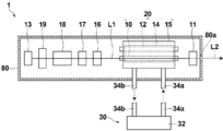
- FIG. 1 is a plan view schematically showing an internal configuration of the solid-state laser device 1 of the embodiment.
- FIG. 2 is a perspective view schematically showing the laser rod 10, the flash lamp 12, and the reflector 14 of the embodiment.
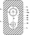
- FIG. 3 is a cross-sectional view taken along a line AA perpendicular to the length direction of the laser rod 10 of FIG.
- the scale of each component in the drawings is appropriately changed from the actual one.
- the solid-state laser device 1 of the embodiment is a laser lamp 10 made of alexandrite and a flash lamp that outputs excitation light for exciting the laser rod 10, and the lamp glass tube 12 a has a wavelength of 200 nm to 300 nm (200 nm or more).
- a flash lamp 12 made of quartz glass that blocks deep ultraviolet light having a wavelength of 400 nm or more, and a hole 40 containing at least part of the laser rod 10 and the flash lamp 12,
- the visible light is light having a wavelength of 400 nm to 780 nm or less.
- the solid-state laser device 1 further includes a pair of mirrors 11 and 13 constituting a resonator, a polarizer (polarizer) 16, a shutter 17, a Q switch 18, and a wedge prism pair 19, and a housing 28 and a housing for housing them.
- a cooling device 30 connected to the laser chamber 15 from the outside of the body is provided.
- the pair of mirrors 11 and 13 are arranged so as to face each other on a straight line with the laser rod 10 interposed therebetween, thereby constituting a linear resonator.
- the mirror 116 is a partial transmission mirror, and acts as a so-called output mirror that outputs laser light.
- the mirror 13 is a high reflection mirror and functions as a so-called rear mirror.
- the mirrors 11 and 13 may be referred to as an output mirror 11 and a rear mirror 13, respectively.
- the polarizer 16 extracts only the component linearly polarized in a predetermined direction from the oscillated laser beam.
- the shutter 17 controls the emission of the laser beam, and is controlled to be opened and closed to mechanically block the emission of the laser beam.
- the Q switch 18 performs a so-called Q switch operation so as to generate a high-power pulsed laser beam.
- the housing 28 is formed in a rectangular parallelepiped shape, for example, and has an opening 28a for taking out the laser L2 on the side wall of the portion facing the output mirror 11.
- the solid-state laser device 1 when the flash lamp 12 is turned on with the Q switch 18 in the light blocking state, the laser rod 10 is excited by the excitation light emitted therefrom, and a strong inversion distribution state is formed.
- the Q switch 18 When the Q switch 18 is brought into the light passing state after this state, the light stimulated and emitted from the laser rod 10 resonates between the mirrors 11 and 13 and becomes a high output giant pulse. It is transmitted and emitted out of the resonator.
- the flash lamp 12 and the laser rod 10 that generate heat are cooled by a cooling medium that circulates in the reflector 14.
- the solid-state laser device of the present invention is not limited to one that generates pulsed laser light, and may be configured to operate in a CW (Continuous Wave) mode.
- the laser rod 10 is obtained by processing a crystal of alexandrite (Cr: BeAl 2 O 3 ) into a rod shape.
- the rod shape is a columnar shape in which the distance between the two disks serving as end faces is longer than the diameter of the disk.
- the laser rod 10 functions as a laser medium that receives light energy from the flash lamp 12 and amplifies light of a specific wavelength.
- the light L1 stimulated and emitted from the laser rod 10 is amplified while resonating in the resonator constituted by the mirrors 11 and 13, and then output as a laser L2 (FIG. 1).
- the laser rod 10 is preferably thin and short.
- the in-plane energy density can be increased, so the pulse width can be shortened, and by reducing the length, the resonator length can be shortened, so the pulse width can be shortened.
- the diameter and length of the laser rod is very effective in terms of cost.
- rod diameter Diameter of the cross-section perpendicular to the length direction (circular cross section) of the laser rod 10 phi L is preferably is 4mm or less. More preferably rod diameter phi L is 3mm or less, and more preferably 2.5mm or less. Further, the rod length of the laser rod is preferably 75 mm or less, and more preferably 60 mm or less.
- the flash lamp 12 is an excitation light source that supplies energy for stimulated emission to the laser rod 10.
- a rod-shaped (cylindrical) lamp glass tube 12a in which opposing electrodes are arranged and Xe gas is sealed can be adopted.
- the flash lamp 12 includes terminals (not shown) at both ends of a rod-shaped lamp glass tube 12 a, and the terminals are connected to a power source (not shown) disposed outside the housing 28.
- the flash lamp 12 is made of quartz glass whose lamp glass tube 12a blocks deep ultraviolet rays having a wavelength of 200 nm to 300 nm and transmits visible light having a wavelength of 400 nm or more.
- the quartz glass used here transmits light having a wavelength of at least 400 nm to 780 nm.
- the lamp glass tube 12a preferably transmits light having a wavelength of 380 nm to 780 nm and blocks light having a wavelength of 300 nm or less.
- “transmitting” a certain wavelength ⁇ means that the transmittance with respect to the light having the wavelength ⁇ is 80% or more, and “blocking” a certain wavelength ⁇ means light having the wavelength ⁇ .
- the transmittance with respect to is to be 5% or less.
- the lamp glass tube 12a preferably has a transmittance for light with a wavelength of 400 nm to 780 nm of 85% or more, more preferably 90% or more. Further, the transmittance for deep ultraviolet light having a wavelength of 200 nm to 300 nm is preferably 3% or less, and more preferably 1% or less.
- quartz glass satisfying the above conditions examples include quartz glass M382S Plus manufactured by Heraeus.
- the lamp glass tube 12a is preferably subjected to an aging treatment.
- the aging treatment is preferably at least 1 million shots (28 hours) and 4 million shots (about 110 hours). It has been clarified by the inventors that the lamp glass tube 12a made of quartz glass has a light transmittance that suddenly decreases from the initial state to 1 million shots (examples described later).
- the change in transmittance with respect to light having a wavelength of 400 nm is changed to a glass tube within 5% while the lamp glass tube 12a is shot from 4 million shots to 14 million shots when the flash lamp 12 is driven.
- one shot refers to one flash that causes the flash lamp to emit light once.
- the relationship between the number of shots and the driving time is converted when the flash lamp is driven at 10 Hz.
- the length of the flash lamp 12 may be appropriately determined according to the length of the laser rod 10. Even if the distance between the electrodes of the flash lamp 12 is made longer than that of the laser rod 10, the excitation light is not absorbed by the laser rod 10 and is lost, so the distance between the electrodes is formed to be approximately the same as the light receiving length of the laser rod 10. It is preferred that Therefore, when the length of the laser rod 10 is 75 mm, the total length of the flash lamp 12 is about 120 mm, and when the length of the laser rod 10 is 60 mm or less, the total length of the flash lamp 12 is about 100 mm.
- the length of the flash lamp 12 is defined by the length in the longitudinal direction including the terminals.
- Diameter flash lamp 12 phi F it may also be appropriately determined in accordance with the rod diameter phi L.
- the lamp diameter ⁇ F is larger than the rod diameter ⁇ L , the ratio of the most efficient excitation light that reaches the laser rod 10 directly from the flash lamp 12 decreases. Therefore, in general, the lamp diameter and the rod diameter are approximately the same.
- the lamp diameter phi F is, for example, such as about 5 mm, is preferably not less than 1.5 times the rod diameter phi L. That is, the lamp and the diameter and the rod diameter, it is preferable to satisfy the 1.5 ⁇ L ⁇ ⁇ F.
- the reflector 14 is entirely composed of a PTFE porous body, that is, composed of only a PTFE porous body.
- reflectors have a reflective surface with a gloss coating on alumina ceramic, or those with a reflective surface packed with barium sulfate, but the main body and the reflective surface are made of different materials.
- the reflecting surface is deteriorated due to distortion due to the difference in thermal expansion coefficient.
- the reflector 14 constituting the reflection surface (the inner wall surface 42 of the hole 40) is made of only PTFE, such a problem does not occur.
- the light emitted from the flash lamp 12 is directly applied to the laser rod 10, or reflected by the inner wall surface 42, which is a reflection surface, and applied to the laser rod 10. .
- the hole portion 40 of the reflector 14 has a columnar shape shorter than the long axis length of the laser rod 10, and the laser rod 10 and the flash lamp 12 are inserted into the hole portion 40, and are parallel to each other in the hole portion 40. Is supported in a state exposed from the hole 40.
- the shape of the hole 40 is not limited as long as at least a part of the laser rod 10 and the flash lamp 12 can be received. However, it is possible to efficiently irradiate the laser rod 10 with the excitation light by accommodating the entire pumping light output region of the flash lamp 12. This is preferable.
- the distance D between the centers of the two is preferably as short as possible. By setting the center distance D to 7 mm or less, the excitation efficiency can be made very high.
- a cooling device 30 that is a cooling water introduction / extraction mechanism for introducing cooling water for cooling the laser rod 10 and the flash lamp 12 to / from the hole 40 is connected to the laser chamber 15 including the reflector 14. Yes.
- the cooling device 30 includes, for example, cooling water such as pure water, and includes a cooling control unit 32 that controls circulation of the cooling water, a pipe 34a and a pipe 34b, and a pipe 34a and a return path of the cooling water as a forward path of the cooling water. It is connected to the laser chamber 15 through a pipe 34b.
- the cooling medium supplied to the laser chamber 15 through the pipe 34 a takes the heat of the laser rod 10 and the flash lamp 12 while passing through the reflector 14, and then returns to the cooling control unit 32 through the pipe 34 b. come. Then, the cooling medium cooled by the cooling control unit 32 circulates between the laser chamber 15 and the cooling control unit 32 again.
- the reflector 14 is made of a porous body of PTFE, so there is a possibility that the alcohol or oil may permeate into the PTFE.
- water particularly pure water is used as the cooling medium. Since water has an effect of absorbing deep ultraviolet rays, the effect of further suppressing the deep ultraviolet rays having a wavelength of 200 nm to 300 nm that are slightly output from the flash lamp 12 from entering the inner wall surface 42 of the reflector 14 can be obtained. Can do.
- the shape of the hole 40 is such that the inner wall surface 42 has the shortest distance t F from the surface of the lamp glass tube 12 a of the flash lamp 12, and It is preferable that the difference from the shortest distance t L from the surface of the laser rod 10 is within ⁇ 1 mm.
- the lamp diameter ⁇ F is larger than the rod diameter ⁇ L , in order to make the distance t F and the distance t L equal, the lamp insertion side and the rod insertion side of the hole 40 are different. It has an asymmetric cross-sectional shape.
- the distance between the surface of the flash lamp 12 facing the inner wall surface 42 of the lamp glass tube 12a (the surface forming the upper semicircle of the lamp glass tube in the cross-sectional view) and the inner wall surface 42 is constant at t F throughout the region. It is preferable from the viewpoint of the reflection efficiency of excitation light and the cooling efficiency by cooling water. Similarly, from the viewpoint of cooling efficiency, the distance between the surface of the laser rod 10 facing the inner wall surface 42 (the surface forming the lower semicircle of the laser rod in the sectional view) and the inner wall surface 42 is constant at t L in the entire region. To preferred.
- the distance t F between the lamp glass tube 12a of the flash lamp 12 and the inner wall surface 42 is preferably 5 mm or less, 1 mm or more, more preferably 2 mm or less, for example, 1.5 mm. Can do. Incidentally, as the distance t F is small, increase the reflection efficiency of the excitation light, it is possible to improve the radiation efficiency of the excitation light to the laser rod. On the other hand, by a distance t F and above 1 mm, it is possible to maintain the flow rate of the cooling water can sufficiently implement the flash lamp cooling.
- the solid-state laser device of the present invention is not limited to the above embodiment.
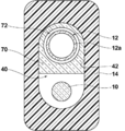
- FIG. 4 to 6 are cross-sectional views schematically showing other embodiments in which the internal configuration of the reflector 14 is different.
- the embodiment shown in FIG. 4 is different from the configuration shown in FIG. 2 in that the flow tube 50 is fitted in the hole 40 of the reflector 14.
- the flow tube 50 has a first fluid flow part 52 into which the flash lamp 12 is inserted, and a second fluid flow part 54 into which the laser rod 10 is inserted.
- the first fluid flow part 52 is a hollow portion having a diameter greater than the diameter phi F flash lamp 12, the cooling medium is flowed to cool the flashlamp 12.
- the second fluid flow part 54 is a hollow portion having a diameter greater than the diameter phi L of the laser rod 10, the cooling medium is flowed to cool the laser rod 10.
- the hollow portion of the diameter of the lamp diameter phi 2 mm ⁇ 10 mm than F of the first fluid flow part 52 preferably is preferably as about 2 mm ⁇ 6 mm larger.
- the second hollow portion of the diameter of 2 mm ⁇ 10 mm than the rod diameter phi L of the fluid flowing section 54 preferably it is preferable to assume approximately 2 mm ⁇ 6 mm larger.
- the flow tube 50 is made of quartz glass equivalent to the lamp glass tube 12a of the flash lamp 12 that blocks deep ultraviolet rays having a wavelength of 200 nm to 300 nm and transmits visible light having a wavelength of 400 nm or more. Is preferred.
- the lamp glass tube 12a and the flow tube 50 of the flash lamp 12 both have the effect of blocking deep ultraviolet rays having a wavelength of 200 nm to 300 nm, so that a double blocking effect can be obtained, and the light generated in the flash lamp 12 Of these, the incidence of deep ultraviolet rays on the inner wall surface 42 of the reflector 14 can be more effectively suppressed.
- the flow tube 50 shown in FIG. 4 may be manufactured and fitted separately from the reflector 14 or may be integrally formed.
- the fluid flow portion 62 is a hollow portion having a diameter greater than the diameter phi F flash lamp 12, the cooling medium is flowed to cool the flashlamp 12.
- the flow tube 60 is made of quartz glass equivalent to the lamp glass tube 12a of the flash lamp 12 that blocks deep ultraviolet light having a wavelength of 200 nm to 300 nm and transmits visible light having a wavelength of 400 nm or more. It is preferable.
- the lamp glass tube 12a and the flow tube 60 of the flash lamp 12 both have the effect of blocking deep ultraviolet rays having a wavelength of 200 nm to 300 nm, so that a double blocking effect can be obtained, and the light generated in the flash lamp 12 Of these, the incidence of deep ultraviolet rays on the inner wall surface 42 of the reflector 14 can be more effectively suppressed.
- the flow tube 60 has a hollow cylindrical shape.
- the flow tube 70 having one fluid flow portion 72 is disposed in the flash lamp arrangement region of the hole portion 40 of the reflector 14. It may be arranged so as to be embedded (upper part of the hole 40).
- cooling water is supplied to the fluid flow part 72 and the lower part of the hole part 40 and cooling water for cooling the laser rod 10 is also supplied to the hole part 40 of the reflector 14 in which the flow tube 60 is loaded. Will flow. Also in the configuration shown in FIG. 6, the same effect as the configuration in FIG. 5 can be obtained.
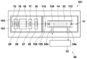
- FIG. 12 is a perspective view schematically showing the external shape of a solid-state laser device according to the second embodiment of the present invention.
- FIGS. 13 and 14 are a schematic side view and a schematic plan view of the solid-state laser device according to the present embodiment, respectively, in which a part of the housing is omitted and the arrangement of internal components is schematically shown.
- the same components as those of the solid-state laser device 1 of the first embodiment are denoted by the same reference numerals, and detailed description thereof is omitted.
- the solid-state laser device 101 includes a pair of mirrors 11 and 13 constituting a resonator, a laser rod 10 disposed in the resonator, and a laser chamber 130 that houses at least a part of the laser rod 10.
- the solid-state laser device 1 includes an aperture member 115 between the mirror 12 and the laser rod 13 as an optical member in addition to a polarizer (polarizer) 16, a shutter 17, a Q switch 18 and a wedge prism pair 19. ing.
- the mirrors 11 and 13, the laser rod 10, and the optical members 16 to 19 and 115 are arranged in the housing 150.
- a part of the laser chamber 130 is exposed to the outside from the housing 150, and the flash lamp 112 is accommodated in a portion exposed from the housing 150 of the laser chamber 130.
- the housing 150 includes a flat base 151, a side wall 153, and a lid 155, and includes an emission opening 156 for outputting laser light to a part of the side wall 153.
- the housing 150 includes the output mirror 11 and the first accommodating portion 150a that accommodates the laser rod 10 or the second portion 132 in which the laser rod 10 of the laser chamber 130 is accommodated, the rear mirror 13 and And a second accommodating portion 150b that accommodates the optical members 16-19.
- the main optical members such as the Q switch and the shutter are accommodated in the second accommodating portion 150b, while the aperture member 115 is accommodated in the first accommodating portion 150a.
- the first housing portion 150a and the second housing portion 150b are separated inside the housing 150 by a partition plate 158 having an opening 158a in the optical path.
- a partition plate 158 By providing the partition plate 158 between the shutter 17 and the laser rod 10, it is possible to suppress dust generated by sliding of the shutter sliding portion on the optical path in the vicinity of the laser rod 10 and the laser rod 10. .
- the opening 158a provided in the partition plate 158 is preferably larger than the diameter of the laser rod 10 to such an extent that adjustment of the optical axis is unnecessary. Note that, as described above, the partition plate 158 is preferably provided inside the housing 150, but the partition plate 158 may not be provided.
- the heights of the first storage portion 150a and the second storage portion 150b are different, and the first storage portion 150a has a first lid that opens the first storage portion 150a.
- the body 155a is provided, and the second housing part 150b is provided with a second lid 155b that opens the second housing part 150b.
- the lid portion 155 of the housing 150 includes a first lid body 155a and a second lid body 155b, and the first housing portion 150a and the second housing portion 150b can be opened independently of each other. ing.
- the first housing portion 50a is closed and only the second housing portion 150b is opened for work. It is possible to prevent dust from entering the first housing portion 150a.
- the base 151 and the side wall portion 153 of the housing 150 are basically made of a strong metal such as aluminum.
- a laser chamber 130 is installed in the first housing 150a of the housing.
- the flash lamp 12 inserted into the laser chamber 130 has a structure in which a positive and negative electrode is provided in a glass tube filled with gas, and in order to start discharge between the electrodes, the conductor around the electrode is charged from several thousand volts. It is necessary to apply a high voltage of tens of thousands of volts. In this configuration, discharge is started by applying a high voltage to the laser chamber 130. Therefore, as the first lid 155a close to the laser chamber 130, a resin material having low conductivity is preferable from the viewpoint of electrical safety.
- the flash lamp 12 when the flash lamp 12 is driven, it generates heat of several hundred watts, and the temperature of the main part 150a is remarkably increased. Therefore, a portion other than the first lid 155a of the first accommodating portion 150a, that is, in this configuration, the side wall portion 153 of the casing 150 and the number of digits (order) of the linear thermal expansion coefficient are made of the same material. It is preferable.
- modified PPO polyphenylene oxide
- Resin materials such as PPE (polyphenylene ether) and polycarbonate having a linear thermal expansion coefficient of 70.0 ⁇ 10 ⁇ 6 (/ ° C.) are suitable.
- each housing portion 150a is formed by using one surface of the side wall 153 of the housing 150 as a lid.
- 150b may be configured to be openable.
- the output mirror 11 is a plane mirror, and the mirror 13 is a concave mirror.
- the output mirror 11 and the rear mirror 13 face each other and are attached to each side surface in the short side direction of the side wall portion 153 forming a part of the housing 150.
- the output mirror 11 is attached so that a laser beam can be output from an emission opening 156 provided in a part of the side wall portion 153 of the housing 150.
- the laser chamber 130 is made of, for example, metal, and is configured to accommodate the laser rod 10 and the flash lamp 12 together with the reflector 14.
- the laser chamber 130 has a space for accommodating the laser rod 10 and the flash lamp 12 inside, and transmits the light emitted from the flash lamp 12 to the laser rod 10 inside.
- a reflection surface is formed inside the laser chamber 130, and the light emitted from the flash lamp 12 is directly applied to the laser rod 10 or reflected by the reflection surface and applied to the laser rod 10.
- FIG. 15 is a perspective view showing the external appearance of the laser chamber 130.
- the laser chamber 130 has a first portion 131 that houses the flash lamp 12 and a second portion 132 that houses the laser rod 10.
- the first portion 131 is provided with a hole 133 penetrating from one wall surface perpendicular to the longitudinal direction to the other wall surface as a space for accommodating the flash lamp 12, and the second portion 132 is provided with the laser rod 10.
- a hole 34 penetrating from one wall surface perpendicular to the longitudinal direction to the other wall surface is provided.
- the two holes 133 and 134 are provided in parallel with each other along the longitudinal direction of the laser chamber 130.
- the first portion 131 of the laser chamber 130 constitutes a holding unit that holds the flash lamp 12 in the solid-state laser apparatus of this embodiment on the side opposite to the base 151 of the laser rod 10 in parallel with the laser rod 10.
- the hole 134 of the laser chamber 130 has a columnar shape shorter than the long axis length of the laser rod 10, and the laser rod 10 is inserted in the hole 134 and supported with both ends exposed from the hole 134.
- the lamp 12 is inserted through the hole 133 and supported (see FIG. 13).
- the shape of the hole 134 is not limited to a cylindrical shape as long as the laser rod 10 can be received, and may be a prismatic shape or an elliptical column shape.
- the flash lamp 12 can be inserted into and removed from the laser chamber 130 in the longitudinal direction, on the right side in the drawing.
- the longitudinal length of the first portion 131 of the laser chamber 130 is longer than the longitudinal length of the second portion 132. Note that the length in the longitudinal direction of the first portion 131 and the second portion 132 may be the same.
- the first portion 131 that accommodates the flash lamp 12 protrudes from the lid 155 of the housing 150, and the second portion 132 that accommodates the laser rod 10 is the housing 150.
- the flash lamp 12 is supported by the support base 23 so as to be disposed inside, and the flash lamp 12 can be replaced with the lid 155 closed.
- the flash lamp 12 can be pulled out from the first portion 131 of the laser chamber to the output mirror 11 side.
- a height h 1 from the surface of the base 151 to the position of the upper end 11 e of the output mirror 11 is lower than a height h 2 to the lower end of the flash lamp 12 accommodated in the first portion 131 of the laser chamber 130.
- An output mirror 11 is attached to the position. Further, no other optical member is provided between the laser rod 10 and the output mirror 11. Therefore, the flash lamp 12 can be easily pulled out from the hole 134 toward the output mirror 11 in the long direction.
- FIG. 16 shows a front view (left view) and a side view (right view) of the output mirror 11.
- the output mirror 11 is a plane mirror, and includes a reflective coating film 11b made of a multilayer film on the surface of a flat substrate 11a as a resonator surface.
- a plane mirror has a portion where a reflective coating film is not formed on the periphery of the surface of the base material.
- the output mirror 11 in the present embodiment excludes a part of the lower end and a part of both ends.
- the reflective coating film 11b is formed uniformly up to the upper end 11e.
- Such an output mirror 11 can be produced, for example, by cutting one end of a commercially available flat mirror that does not have a reflective coating film formed on its periphery.
- the distance between the centers of the two is closer. Since the output mirror 11 can be used as a reflecting surface up to the upper end 11e, the flash lamp 12 can be pulled out to the output mirror 11 side and the lower end position of the flash lamp 12 does not overlap the optical path as much as possible. It can be arranged at a position close to the axis (laser optical axis), and miniaturization is also possible. In particular, when the distance between the centers of the flash lamp 12 and the laser rod 10 is 7 mm or less, the excitation efficiency can be made extremely high.
- the solid-state laser device 101 includes the aperture member 115, the polarizer 16, the shutter 17, the Q switch 18, and the wedge prism pair 19 as optical members on the rear mirror 13 side of the laser rod 10.
- the aperture member 115 has an opening 115a in the optical path, and blocks stray light greatly deviating from the optical path toward the laser rod side at a relatively large angle from the optical member 16-19 side.
- the wedge prism pair 19 is provided for performing optical system adjustment such as optical axis correction by adjusting the position and angle thereof.
- optical system adjustment such as optical axis correction by adjusting the position and angle thereof.
- the wedge prism pair 19 it is possible to perform optical axis adjustment with very high accuracy.
- the aperture member 115 is disposed closest to the laser rod 10, the aperture member 115 is a laser of stray light generated in the polarizer 16, the shutter 17, the Q switch 18, the wedge prism pair 19, the rear mirror 13, and the like. Progress toward the rod 10 side can be suppressed.
- the aperture member 115 is required to generate less dust and outgas, absorb less laser light, and have heat resistance. Further, a material having diffusibility with respect to laser light is desirable. Therefore, as the material of the aperture member 115, ceramic, ground glass, or fluororesin such as polytetrafluoroethylene (PTFE) is suitable.
- PTFE polytetrafluoroethylene
- the aperture member 115 be disposed between the laser chamber 130 and the other optical members 16 to 19 as in this embodiment in order to prevent stray light from hitting the laser chamber 130.
- Optical members 115 and 16 to 19 are attached to holders 125 and 26 to 29, respectively, and the holders 125 and 26 to 29 are installed on a base 151 that forms part of the casing 150. These optical members 115 and 16 to 19 may be provided as necessary. In the solid-state laser device of the present invention, among these optical members, for example, a configuration including only a Q switch may be used. Good.
- the height of the optical members 16 to 19 excluding the aperture member 115 from the base 151 is as follows. , Both are higher than the height h 2 of the lower end of the flash lamp 12.
- the heights of the rear mirror 13 and the optical members 115 and 16 to 19 include the holders 125 and 26 to 29 that support them, and are most separated in the direction perpendicular to the surface of the base 151 parallel to the resonator optical axis. Define the position.
- the height h 3 of the rear mirror 13 is a distance from the surface of the base 151 to the upper end of the rear mirror holder
- the height h 4 of the Q switch 18 is a distance from the surface of the base 151 to the upper end of the holder 28. (See FIG. 2).
- the holders of optical members such as the rear mirror 13 and the Q switch 18 that are to be arranged on the optical path have a height necessary for accurately supporting these optical members on the optical axis, and use commercially available ones. In this case, it is difficult to reduce these heights. If these high optical members are arranged on the output mirror 11 side of the laser rod 10, the flash lamp 12 may not be pulled out.
- an optical member having a height that blocks a trajectory when the flash lamp 12 is pulled out is not disposed on the output mirror 11 side, and the optical member is higher than the height h 2 at the lower end of the flash lamp 12.
- the optical member is higher than the height h 2 at the lower end of the flash lamp 12.
- the output mirror 11 and the rear mirror 13 constitute a linear resonator, and all the optical members other than the output mirror 11 are arranged on the laser rod 10 and the rear mirror 13 side.
- the resonator portion of the solid-state laser device can be made very small, and downsizing of the entire device can be realized.
- the accommodating part 150b can be made further smaller, and the housing can be further reduced in size.
- the resonator length is 280 mm or less
- the resonator width is 70 mm or less
- the height is 60 mm or less.
- the resonator portion can be configured.
- the resonator length is the distance between the reflecting surfaces of the output mirror 11 and the rear mirror 13, and the width and height of the resonator are defined by the largest portion of the holder of the optical member disposed in the resonator.
- the area of the base of the solid-state laser device can be 56000 mm 2 (560 cm 2 ) or less.
- a pulse laser with a pulse width of 40 nsec (n seconds) or less can be oscillated when driven with an input power of 22 J or less. Note that it is possible to oscillate a pulse laser having a pulse width of 30 nsec or less at the input electrode 18J or less.
- a pulse width of 40 nsec or less can be realized by using a laser rod having a diameter of 3 mm or less, and further, a pulse width of 30 nsec or less can be realized by setting the diameter to 2.5 mm or less.
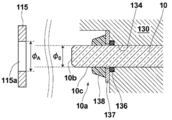
- FIG. 17 shows an enlarged cross-sectional view of the vicinity of one end of the laser rod 10 exposed from the laser chamber 130 (region A surrounded by a broken line in FIG. 13). In FIG. 17, a cross section of the aperture member 115 is also shown.
- an O-ring 136 is disposed at the root of the end 10a of the laser rod 10 (hereinafter referred to as “rod end 10a”) exposed from the hole 134 of the laser chamber 130.
- an O-ring pressing plate 137 Adjacent to the ring 136, an O-ring pressing plate 137 having a through hole through which the laser rod 10 passes is disposed on the end surface 10 b (hereinafter referred to as “rod end surface 10 b”) side of the laser rod 10.
- the inside of the laser chamber 130 is a flow path for a cooling medium, and the insertion portion of the laser rod 10 and the flash lamp 12 is appropriately sealed with an O-ring or the like for sealing.
- the exposed root of the rod end 10a from the laser chamber 130 is the portion of the rod end 10a exposed from the hole 134 of the laser chamber 130 that is closest to the laser chamber 130 (that is, the hole 134).
- the exposed root from the hole 134 of the laser chamber 130 may be referred to as the exposed root from the laser chamber.
- the O-ring 136 is fitted into the laser rod 10 and is disposed in an O-ring receiving portion provided at the end of the hole 134 of the laser chamber 130. When the O-ring pressing plate 137 is screwed to the laser chamber 130, the O-ring 136 is biased toward the laser chamber 130, and the laser rod 10 is fixed.
- the O-ring of stray light generated in the housing 150 is formed on the side surface 10c of the laser rod closer to the rod end surface 10b than the O-ring 136 fitted in the rod end portion 10a (hereinafter referred to as “rod side surface 10c”).
- a cover member 138 is provided to prevent the incident on 136.
- the O-ring 136, the O-ring pressing plate 137, and the cover member 138 are preferably provided at both ends exposed from the laser chamber 130, but may be provided at least at one end.
- the cover member 138 has a function equivalent to that of the O-ring pressing plate 137, the O-ring pressing plate 137 may not be provided.
- a laser rod that is a solid-state laser medium is an optical path itself, and a member that touches the laser rod is almost in contact with the optical path.
- an O-ring 136 exists in the very vicinity of the rod end surface 10b, and if dust or gas is generated in the O-ring 136, it is likely to adhere to the rod end surface 10b.
- the cover member 138 since the cover member 138 is provided, stray light can be prevented from entering the O-ring 136, so that generation of dust and outgas can be effectively suppressed. .
- the cover member 138 is required to have a small amount of dust and outgas, a small amount of laser light absorption, and heat resistance. Moreover, it is desirable to have a diffusibility with respect to a laser beam. Therefore, the cover member 138 is preferably made of at least one of a fluororesin such as ceramic, ground glass, or PTFE. The cover member 138 is preferably made of a soft material having high adhesion to the laser rod 10 in order to prevent stray light from entering the O-ring 136. Accordingly, fibrous ceramics or glass, or unfired fluororesin is particularly suitable.
- the opening diameter of the aperture member 115 is preferably in the rod diameter phi 0 equal or more, and more preferably greater than rod diameter phi 0.
- the aperture limitation by the aperture member 115 is a laser output.
- the stability is lowered when the arrangement accuracy of the aperture member 115 is low, while the arrangement accuracy is reduced.
- the aperture shape of the aperture member 115 is preferably similar to the end surface shape of the laser rod 10.
- the aperture member 115 is disposed only on the rear mirror 13 side of the laser rod 10, but the aperture member 115 is disposed on both end surfaces of the laser rod 10 from the viewpoint of protection by blocking stray light. Is preferred.
- the aperture members 115 are arranged on both end surfaces of the laser rod 10, the requirement for arrangement accuracy increases, leading to an increase in manufacturing cost. This is particularly noticeable when the rod has a small diameter.
- the aperture member 115 is arranged only on one side. A sufficiently high protective effect can be obtained.
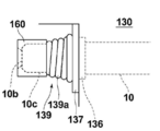
- FIG. 18 shows an enlarged view of the vicinity of the end of the laser rod provided with the cover member 139 of the design change example.
- the cover member 139 shown in FIG. 18 is formed by winding a tape 139a made of PTFE around the rod side surface 10c a plurality of times.
- the cover member 139 configured by winding the tape 139a a plurality of times has high adhesiveness with the laser rod 10, and the size can be freely changed depending on the number of windings, which is preferable.
- the tape 139a is wound to such an extent that the O-ring 136 is not visible when viewed from the rod end face 10b side, stray light can be effectively prevented from entering the O-ring 136.
- the O-ring pressing plate may not be provided.
- the O-ring 136 a general rubber made of non-fluorine resin can be used.
- the O-ring 136 itself is made of a material that generates less dust and outgas, for example, a fluororesin rubber.
- stray light may enter the O-ring pressing plate 137 to generate dust and outgas. It is preferable to use a material that generates less dust and outgas, for example, ceramic or fluororesin. Alternatively, it is also preferable that the cover member is enlarged so that stray light is prevented from entering the O-ring pressing plate.
- the cover members 138 and 139 for suppressing stray light from the laser chamber 130 to the exposed O-ring 136 of the laser rod 10 are provided, damage to the laser rod 10 can be suppressed, and the laser stable for a long time. Output can be obtained. Further, if the aperture member 115 is provided, the incidence of stray light to the laser chamber 130 can be suppressed, and damage to the laser rod 10 can be further effectively suppressed.
- the aperture member 115 and the cover member 138 or 139 are provided at the same end face side of the laser rod 10 at the same time.
- the solid-state laser device of the present invention is not limited to the configuration in which the aperture member and the cover member are simultaneously provided on the same end surface side, and at least the cover member is provided on either the rear side or the output side. It is preferable.
- the combination pattern of the arrangement of the aperture member and the cover member As the minimum configuration, a pattern as shown in Table 1 below can be cited.
- the rear side and the output side mean the rear mirror 13 side and the output mirror 11 side of the laser rod 10, respectively.
- “present” means that an aperture member or cover member is provided, and “ ⁇ ” means that no aperture member or cover member is provided.
- ⁇ means that no aperture member or cover member is provided.
- a combination in which “ ⁇ ” is changed to “present” is also preferable.
- a configuration in which an aperture member and a cover member are provided on both end faces of the laser rod is most preferable.
- the configuration described as the above-described embodiment corresponds to pattern No. 1 in Table 1, and the side on which more optical members such as a Q switch and a shutter are arranged as in this embodiment (the rear side in this embodiment). It is preferable that the aperture member and the cover member are provided at the same time because the incidence of stray light can be suppressed most efficiently and the manufacturing cost can be suppressed.
- FIG. 19 shows a side view (right view) and an end face front view (left view) of one end 10a of the laser rod 10.
- the laser rod 10 includes a chamfered portion 10d between the rod end surface 10b and the rod side surface 10c. That is, the laser rod 10 has a chamfered portion 10d on the outer periphery in the radial direction of the outer periphery of the end surface 10b and the outer periphery of the end surface 10b.
- the chamfered portion 10d is a sand surface.
- An antireflection film 114 is provided on the rod end surface 10b. In FIG. 19, only one end face of the laser rod is shown, but the structure is the same as both end faces.
- the antireflection film 114 is preferably provided on the entire rod end surface 10b.
- the width ⁇ of the chamfered portion 10d which corresponds to the difference between the radius of the end face the outer periphery of the laser rod 10, preferably about 2%.
- the width ⁇ of the chamfered portions 13d and 0.05 mm are the like.
- FIG. 20 shows an enlarged cross-sectional view of the vicinity of one end of the laser rod 10 exposed from the laser chamber 130 (region A surrounded by a broken line in FIG. 13) when another additional configuration is provided.
- the O-ring 136 and an O-ring pressing plate 137 having a through-hole that allows the laser rod 10 to pass on the rod end surface 10 b side are disposed adjacent to the O-ring 136 and the O-ring 136 at the root of the laser rod 10 exposed from the laser chamber 130. Is the same as FIG.
- the end surface protection member 160 further includes an opening defining portion 162 that forms an opening 161 having a diameter ⁇ 2 smaller than the outer diameter ⁇ 1 of the outer periphery of the rod end surface 10 b at a position facing the rod end surface 10 b. It has.
- the end face protection member 160 limits the laser light path area on the rod end face 10b to an area inside the outer periphery of the rod end face 10b.
- the entire region of the laser rod 10 is an optical path, and the cross section of the optical path is equal to a circular cross section having a diameter ⁇ 0 , but by providing the end face protection member 160, the diameter ⁇ indicated by a two-dot chain line in FIG.
- the optical path is limited to two circular cross-sectional areas.
- the laser light path region is limited to a region inside the outer periphery of the rod end surface 10b, that is, the laser light path is limited to a region inside the inner periphery of the chamfered portion 10d.
- the laser beam is not irradiated to the boundary between the rod end surface 10b and the chamfered portion 10d.
- the boundary between the rod end surface 10b and the chamfered portion 10d is an area where the coating of the optical film is not good and tends to be the starting point of coating destruction.
- the end surface protection member 160 it is possible to suppress the occurrence of coating breakage on the rod end surface 10b.
- the end face protection member 160 in the present embodiment has a cylindrical portion 164 that supports the opening defining portion 162, and the cylindrical portion 164 is attached to the rod end portion 10a. It has a cap shape that fits and is attached.
- the shape of the end surface protection member 160 is not particularly limited as long as the opening defining portion 162 can be stably supported and arranged in the vicinity of the rod end surface 10b.
- a cap shape that can be fitted and mounted as in the present embodiment is preferable because the placement accuracy can be easily secured.
- the opening defining portion 162 is provided in the very vicinity of the rod end surface 10b so as to cover the boundary between the rod end surface 10b and the chamfered portion 10d.
- the distance d is preferably 0.5 mm or less, more preferably 0.1 mm or less, and the rod end surface 10 b and the opening defining portion 62 are particularly preferably in contact with each other.
- the distance between the opening defining portion 162 and the rod end surface 10b is provided on the opening defining portion 162 and the rod end surface 10b. It means the distance to the surface of the antireflection film 114.
- the rod end surface 10b and the opening defining portion 162 are in contact means that the surface of the antireflection film 14 provided on the rod end surface 10b and the opening defining portion 162 are in contact.
- the opening defining portion 162 of the end surface protection member 160 is provided with a tapered portion 162a whose opening diameter decreases as the rod end surface 10b becomes closer.
- the distance between the opening defining portion 162 and the rod end face 10b is the aperture-defining portions 162, defined as the distance between the portion and the rod end face 10b located closest to the rod end surface 10b side of the portion constituting the diameter phi 2.
- the aperture-defining portions 162 defined as the distance between the portion and the rod end face 10b located closest to the rod end surface 10b side of the portion constituting the diameter phi 2.
- the end face protection member 160 may be provided on both end faces of the laser rod 10 as long as it is provided on any one end face. Even if only one of them is used, there is an effect of limiting the laser oscillation region.
- the aperture limit greatly affects the laser output.
- the end face protection member has high sensitivity to the laser output in terms of production accuracy and placement accuracy, resulting in decreased stability and increased manufacturing costs. May lead to. Therefore, it is desirable to provide the protective member only on one end face.
- the material is required to be free from damage and deformation by the laser beam and to generate less dust and outgas. Therefore, ceramic or fluororesin is suitable as the material for the opening defining portion 162.
- the entire end surface protection member 160 including the opening defining portion 162 is preferably made of at least one of ceramic or fluororesin.
- FIG. 23 is a cross-sectional view showing a design change example of the end face protection member.
- the opening defining portion 162 is in contact with the rod end surface 10b (here, the antireflection film 114 formed on the rod end surface 10b), and the cylindrical portion 164A is the laser rod of the laser chamber 130.
- 10 has a length that abuts against an O-ring pressing plate 137 provided at the exposed base of the ten. In this way, the cover-like shape covering the entire exposed portion of the rod side surface 10c of the end portion 10a of the laser rod 10 exposed from the laser chamber 130 can improve the arrangement accuracy of the opening defining portion 162 with respect to the rod end surface 10b. This is preferable.
- the stray light generated in the housing 150 is generated in the O-ring 136 provided at the exposed root of the laser rod 10 from the laser chamber 130 by providing the end surface protection member 160A having a shape covering the exposed root of the laser rod 10. Can be prevented from entering.
- the end surface protection member 160A may cause damage to the O-ring 136. Since the incidence of stray light can be suppressed, damage to the laser rod can be more effectively prevented.
- FIG. 24 is an enlarged cross-sectional view of the exposed portion of the laser rod 10 from the laser chamber 130 when the cover member 138 and the end face protection member 160 are provided in combination.
- the cover member 138 and the end face protection member 160 By providing the cover member 138 and the end face protection member 160, the entire area of the side surface 10c of the rod end portion 10a is covered in the same manner as the end face protection member 160A shown in FIG.
- the cover member 138 can prevent stray light from entering the O-ring 136, so that the generation of dust and gas can be effectively suppressed. Damage can be effectively suppressed, and further long-term stability can be realized.
- the aperture member 115, the cover member 138 or 139, and the end surface protection member 160 or 160A are preferably provided simultaneously on the same end surface side of the laser rod 10. However, it is not always necessary to provide all of them at the same time, and all of the solid-state laser devices of the present invention are additionally provided.
- the arrangement pattern shown in the following Table 2 is mentioned as an arrangement pattern having a preferable minimum configuration.
- the rear side and the output side mean the rear mirror 13 side and the output mirror 11 side of the laser rod 10, respectively.
- “present” means that an aperture member, a cover member, or an end face protection member is provided, and “ ⁇ ” means that it is not provided.
- ⁇ means that it is not provided.
- a combination in which “ ⁇ ” is changed to “present” is also preferable.
- an aperture member is provided on the rear side where many optical members are arranged as in the above configuration.
- the end surface protection member is assumed to be a cap-shaped fitting type that does not require alignment of the optical axis, and the end surface protection member is preferably provided on at least one end surface, and is provided on both ends. It is more preferable.
- FIG. 26 is a perspective view schematically showing the external shape of a solid-state laser device according to the third embodiment of the present invention.
- FIGS. 27 and 28 are a schematic side view and a schematic plan view of the solid-state laser device according to the present embodiment, respectively, in which a part of the housing is omitted and the arrangement of internal components is schematically shown.
- a sealing terminal 135 having a socket or a plug having an electrode is provided at one end (here, one end on the rear mirror 13 side) of the hole 133 that accommodates the flash lamp 12 of the laser chamber 130. Is provided. That is, one end of the hole 133 has an abutting structure in which the terminal of the electrode is embedded.
- the flash lamp 12 is inserted into the hole 133 from the right side in FIG. 27, butts against the sealing terminal 135 and is connected to the power supply terminal.
- the hole 133 that accommodates the flash lamp 12 has an abutting structure, so that the positioning of the flash lamp 12 at the time of replacement becomes easy, and the excitation efficiency decreases due to the displacement of the flash lamp 12 at the time of replacement. Etc. can be prevented.
- the cooling medium pipes 34a and 34b connected to the laser chamber 130 extend in the horizontal direction, whereas the solid-state laser of the present embodiment.
- the pipes 35 a and 35 b are bent in an L shape, and are disposed so as to extend in a direction perpendicular to the base toward the base 151 along the wall surface of the side wall portion 153 of the housing 150.
- a hole is provided outside the side wall 153 of the base 151, and the pipes 35 a and 35 b are connected to the cooling device 32 disposed below the base 151 through the hole.
- the pipes 35a and 35b are connected to the laser chamber 130 by a rigid member such as a metal, and from the rigid member to the cooling device 32, the pipes 35a and 35b are configured by a soft member such as a hose that can be removed. Is preferred.
- the base 151 is fixed to a frame having a space under the base 151 to support the housing 150, and a cooling device is installed under the base 151. Then, it is not necessary to consider a space larger than the width of the base as the installation space.
- the solid-state laser devices of the second and third embodiments include a linear resonator in which an output mirror and a rear mirror are arranged on a straight line, a laser rod arranged on the optical path of the resonator, and at least a Q switch And an excitation light source comprising a flash lamp that emits excitation light for exciting the laser rod, and is a rod-like excitation light source extending in parallel with the laser rod, and the resonator, the laser rod, and the optical member have a common base
- a solid-state laser device that is provided on a base and is enclosed in a casing that includes the base, and a holding unit that holds the excitation light source parallel to the laser rod on the side opposite to the base of the laser rod
- an optical member including a Q switch is disposed between the laser rod and the rear mirror, and the upper end position of the output mirror is held by the holding unit with reference to the base.
- the holding part is configured to hold the excitation light source so that it can be inserted into and removed from the output
- FIG. 7 shows the result.
- the solid-state laser device of the example is a solid-state laser device 1 having the configuration shown in FIGS. 1 and 2, and transmits light having a wavelength of 200 nm to 300 nm as a glass tube 12a for a lamp. It is equipped with a flash lamp using quartz glass (M382 S Plus from Heraeus).
- the solid state laser device of the comparative example is quartz glass (M382 of Heraeus Co., Ltd.) that transmits broadband light having a wavelength of 400 nm to 2000 nm as a lamp glass tube 12a and has a transmittance of 25% with respect to light having a wavelength of 250 nm. Plus) is equipped with a flash lamp using.
- FIG. 7 shows the change over time of the laser output when the shots are taken at 10 Hz for 450 to 500 hours in the apparatus of each example, normalized by the initial values.
- the laser output of the comparative example gradually decreases with time, whereas the laser output of the example shows a rapid decrease in the initial 25 hours (900,000 shots) and then 400 hours or more after showing a sharp decrease.
- a stable output was obtained with a fluctuation rate within about 5%.
- the rapid change in the laser output of the example in the early stage is due to deterioration of the quartz glass used in the lamp glass tube 12a of the flash lamp by ultraviolet light, and the quartz glass does not change after 25 hours. The output is estimated to be stable.
- the change in laser output over time behaves almost the same as the change in transmittance of quartz glass, and if the characteristics of quartz glass are subjected to an aging treatment for a certain time or longer, each wavelength ( For example, it is considered that the variation in transmittance with respect to 400 nm is within about 5%.
- the aging processing time is preferably 110 hours or less and 4 million shots or less.
- the application of the solid-state laser device of the present invention is not particularly limited, and can be used for various applications.
- laser light particularly pulsed laser light
- It can be preferably used as a measurement light source.
- the solid-state laser device of the present invention can also be applied to other devices such as a processing device that processes a material using laser light and an analysis device that analyzes a sample using laser light. .
Abstract
L'invention porte sur un dispositif laser à solide pouvant générer une oscillation laser stable pendant une longue période de temps. Le dispositif laser à solide (1) comporte : un barreau laser (10) qui est formé à partir d'un cristal d'alexandrite ; une lampe à éclairs (12) qui émet une lumière d'excitation destinée à exciter le barreau laser (10), un tube en verre (12a) pour la lampe étant formé à partir d'un verre de quartz qui bloque au moins la lumière ultraviolette profonde ayant une longueur d'onde de 200 à 300 nm, tout en transmettant la lumière visible ayant une longueur d'onde supérieure ou égale à 400 nm ; et une chambre laser (15) qui contient un réflecteur tubulaire (14) qui est formé à partir d'un corps poreux en polytétrafluoroéthylène et qui est pourvu d'un pore (40) qui contient au moins une partie du barreau laser (10) et une partie de la lampe à éclairs (12), une surface de paroi interne (42) du pore (40) jouant le rôle de surface réfléchissante qui réfléchit la lumière d'excitation.
Priority Applications (1)
| Application Number | Priority Date | Filing Date | Title |
|---|---|---|---|
| US16/200,063 US10587088B2 (en) | 2016-05-27 | 2018-11-26 | Solid-state laser device |
Applications Claiming Priority (4)
| Application Number | Priority Date | Filing Date | Title |
|---|---|---|---|
| JP2016105869 | 2016-05-27 | ||
| JP2016-105869 | 2016-05-27 | ||
| JP2016131364 | 2016-07-01 | ||
| JP2016-131364 | 2016-07-01 |
Related Child Applications (1)
| Application Number | Title | Priority Date | Filing Date |
|---|---|---|---|
| US16/200,063 Continuation US10587088B2 (en) | 2016-05-27 | 2018-11-26 | Solid-state laser device |
Publications (1)
| Publication Number | Publication Date |
|---|---|
| WO2017204358A1 true WO2017204358A1 (fr) | 2017-11-30 |
Family
ID=60412823
Family Applications (1)
| Application Number | Title | Priority Date | Filing Date |
|---|---|---|---|
| PCT/JP2017/019806 WO2017204358A1 (fr) | 2016-05-27 | 2017-05-26 | Dispositif laser à solide |
Country Status (2)
| Country | Link |
|---|---|
| US (1) | US10587088B2 (fr) |
| WO (1) | WO2017204358A1 (fr) |
Families Citing this family (2)
| Publication number | Priority date | Publication date | Assignee | Title |
|---|---|---|---|---|
| EP3467971B1 (fr) * | 2016-05-27 | 2020-07-08 | FUJIFILM Corporation | Dispositif laser à solide |
| US20220013976A1 (en) * | 2020-07-13 | 2022-01-13 | Raytheon Company | High-energy laser apparatus for thin film temperture sensing |
Citations (17)
| Publication number | Priority date | Publication date | Assignee | Title |
|---|---|---|---|---|
| JPS6031284A (ja) * | 1983-07-29 | 1985-02-18 | Toshiba Corp | 固体レ−ザ装置 |
| JPH01304790A (ja) * | 1988-06-02 | 1989-12-08 | Ofic Co | Yagレーザー発振装置 |
| JPH03231481A (ja) * | 1990-02-07 | 1991-10-15 | Toshiba Corp | レーザ発振装置 |
| JPH0423479A (ja) * | 1990-05-18 | 1992-01-27 | Seiko Epson Corp | レーザー装置 |
| JPH0453282A (ja) * | 1990-06-20 | 1992-02-20 | Seiko Epson Corp | レーザー装置 |
| JPH05218530A (ja) * | 1992-01-31 | 1993-08-27 | Hoya Corp | レーザ光学部品保持装置及び固体レーザ装置 |
| JPH07235714A (ja) * | 1994-02-23 | 1995-09-05 | Mitsubishi Electric Corp | 固体レーザ装置 |
| US5805625A (en) * | 1994-02-09 | 1998-09-08 | Walter Langner | Laser |
| JPH11150316A (ja) * | 1997-11-17 | 1999-06-02 | Amada Eng Center Co Ltd | 固体レーザ発振器 |
| JP2003008118A (ja) * | 2001-06-26 | 2003-01-10 | Nec Corp | 固体レーザ装置 |
| JP2003198011A (ja) * | 2001-11-19 | 2003-07-11 | Gsi Lumonics Ltd | 圧接ロッドチューブ |
| WO2003069738A1 (fr) * | 2002-02-15 | 2003-08-21 | Mitsubishi Denki Kabushiki Kaisha | Laser solide a barreau |
| JP2005158995A (ja) * | 2003-11-26 | 2005-06-16 | Matsushita Electric Ind Co Ltd | 固体レーザ媒質の励起方法とそれを利用した固体レーザ装置 |
| JP2007096063A (ja) * | 2005-09-29 | 2007-04-12 | Mitsubishi Electric Corp | レーザ装置、レーザ加工方法、被レーザ加工物及び被レーザ加工物の生産方法。 |
| JP2011018815A (ja) * | 2009-07-10 | 2011-01-27 | Toshiba Corp | Yagレーザ発振器 |
| JP2015192044A (ja) * | 2014-03-28 | 2015-11-02 | 富士フイルム株式会社 | 固体レーザ装置及び光音響計測装置 |
| WO2016051664A1 (fr) * | 2014-09-30 | 2016-04-07 | 富士フイルム株式会社 | Dispositif laser à l'état solide |
Family Cites Families (5)
| Publication number | Priority date | Publication date | Assignee | Title |
|---|---|---|---|---|
| US3979696A (en) * | 1975-06-30 | 1976-09-07 | Hughes Aircraft Company | Laser pumping cavity with polycrystalline powder coating |
| JPS6031264A (ja) | 1983-07-29 | 1985-02-18 | Sharp Corp | Ic及びlsiのラッチアップ防止回路 |
| JPH1187806A (ja) | 1997-09-04 | 1999-03-30 | Amada Eng Center:Kk | 固体レーザ発振装置 |
| JP3401564B2 (ja) * | 2000-07-31 | 2003-04-28 | 独立行政法人産業技術総合研究所 | 光源一体型集光発光装置 |
| US9246299B2 (en) * | 2011-08-04 | 2016-01-26 | Martin A. Stuart | Slab laser and amplifier |
-
2017
- 2017-05-26 WO PCT/JP2017/019806 patent/WO2017204358A1/fr active Application Filing
-
2018
- 2018-11-26 US US16/200,063 patent/US10587088B2/en active Active
Patent Citations (17)
| Publication number | Priority date | Publication date | Assignee | Title |
|---|---|---|---|---|
| JPS6031284A (ja) * | 1983-07-29 | 1985-02-18 | Toshiba Corp | 固体レ−ザ装置 |
| JPH01304790A (ja) * | 1988-06-02 | 1989-12-08 | Ofic Co | Yagレーザー発振装置 |
| JPH03231481A (ja) * | 1990-02-07 | 1991-10-15 | Toshiba Corp | レーザ発振装置 |
| JPH0423479A (ja) * | 1990-05-18 | 1992-01-27 | Seiko Epson Corp | レーザー装置 |
| JPH0453282A (ja) * | 1990-06-20 | 1992-02-20 | Seiko Epson Corp | レーザー装置 |
| JPH05218530A (ja) * | 1992-01-31 | 1993-08-27 | Hoya Corp | レーザ光学部品保持装置及び固体レーザ装置 |
| US5805625A (en) * | 1994-02-09 | 1998-09-08 | Walter Langner | Laser |
| JPH07235714A (ja) * | 1994-02-23 | 1995-09-05 | Mitsubishi Electric Corp | 固体レーザ装置 |
| JPH11150316A (ja) * | 1997-11-17 | 1999-06-02 | Amada Eng Center Co Ltd | 固体レーザ発振器 |
| JP2003008118A (ja) * | 2001-06-26 | 2003-01-10 | Nec Corp | 固体レーザ装置 |
| JP2003198011A (ja) * | 2001-11-19 | 2003-07-11 | Gsi Lumonics Ltd | 圧接ロッドチューブ |
| WO2003069738A1 (fr) * | 2002-02-15 | 2003-08-21 | Mitsubishi Denki Kabushiki Kaisha | Laser solide a barreau |
| JP2005158995A (ja) * | 2003-11-26 | 2005-06-16 | Matsushita Electric Ind Co Ltd | 固体レーザ媒質の励起方法とそれを利用した固体レーザ装置 |
| JP2007096063A (ja) * | 2005-09-29 | 2007-04-12 | Mitsubishi Electric Corp | レーザ装置、レーザ加工方法、被レーザ加工物及び被レーザ加工物の生産方法。 |
| JP2011018815A (ja) * | 2009-07-10 | 2011-01-27 | Toshiba Corp | Yagレーザ発振器 |
| JP2015192044A (ja) * | 2014-03-28 | 2015-11-02 | 富士フイルム株式会社 | 固体レーザ装置及び光音響計測装置 |
| WO2016051664A1 (fr) * | 2014-09-30 | 2016-04-07 | 富士フイルム株式会社 | Dispositif laser à l'état solide |
Also Published As
| Publication number | Publication date |
|---|---|
| US10587088B2 (en) | 2020-03-10 |
| US20190097379A1 (en) | 2019-03-28 |
Similar Documents
| Publication | Publication Date | Title |
|---|---|---|
| US10431951B2 (en) | Leakage light removal structure and fiber laser | |
| US10389080B2 (en) | Residual light removal structure and fiber laser | |
| WO2017204358A1 (fr) | Dispositif laser à solide | |
| JPH03505506A (ja) | 一体型固体レーザ | |
| WO2017204355A1 (fr) | Dispositif laser à solide | |
| US7577179B2 (en) | Laser irradiation apparatus | |
| US10608405B2 (en) | Solid-state laser device | |
| JP5424320B2 (ja) | 固体レーザ装置 | |
| JP6595712B2 (ja) | 固体レーザ装置 | |
| JP6836043B2 (ja) | ファイバーレーザー装置 | |
| US7099365B2 (en) | Oscillation method and device of fluorine molecular laser | |
| JP2005158886A (ja) | 光増幅器、レーザ発振器およびmopaレーザ装置 | |
| CN117916963A (zh) | 主动冷却端泵浦固态激光增益介质 | |
| RU113082U1 (ru) | Миниатюрный твердотельный лазер с диодной накачкой | |
| KR20010084898A (ko) | 방사형으로 배치된 여러 개의 직선형 다이오드 레이저를이용한 고체레이저 발생장치. | |
| RU114560U1 (ru) | Миниатюрный лазерный излучатель | |
| JP2010098215A (ja) | 固体レーザロッドとその製造方法及び前記固体レーザロッドを用いた固体レーザ装置 | |
| JPH0246786A (ja) | 固体レーザ発振装置 | |
| JPH07115234A (ja) | 高出力レーザー装置 | |
| JPH0260178A (ja) | 固体レーザ発振装置 | |
| JP2008098622A (ja) | レーザー照射装置 |
Legal Events
| Date | Code | Title | Description |
|---|---|---|---|
| NENP | Non-entry into the national phase |
Ref country code: DE |
|
| 121 | Ep: the epo has been informed by wipo that ep was designated in this application |
Ref document number: 17802944 Country of ref document: EP Kind code of ref document: A1 |
|
| 122 | Ep: pct application non-entry in european phase |
Ref document number: 17802944 Country of ref document: EP Kind code of ref document: A1 |
|
| NENP | Non-entry into the national phase |
Ref country code: JP |