WO2017203633A1 - エレベータの巻上機据付方法 - Google Patents
エレベータの巻上機据付方法 Download PDFInfo
- Publication number
- WO2017203633A1 WO2017203633A1 PCT/JP2016/065480 JP2016065480W WO2017203633A1 WO 2017203633 A1 WO2017203633 A1 WO 2017203633A1 JP 2016065480 W JP2016065480 W JP 2016065480W WO 2017203633 A1 WO2017203633 A1 WO 2017203633A1
- Authority
- WO
- WIPO (PCT)
- Prior art keywords
- hoisting machine
- car
- guide rail
- rail
- counterweight
- Prior art date
Links
Images


Classifications
-
- B—PERFORMING OPERATIONS; TRANSPORTING
- B66—HOISTING; LIFTING; HAULING
- B66B—ELEVATORS; ESCALATORS OR MOVING WALKWAYS
- B66B7/00—Other common features of elevators
-
- B—PERFORMING OPERATIONS; TRANSPORTING
- B66—HOISTING; LIFTING; HAULING
- B66B—ELEVATORS; ESCALATORS OR MOVING WALKWAYS
- B66B19/00—Mining-hoist operation
- B66B19/005—Mining-hoist operation installing or exchanging the elevator drive
-
- B—PERFORMING OPERATIONS; TRANSPORTING
- B66—HOISTING; LIFTING; HAULING
- B66B—ELEVATORS; ESCALATORS OR MOVING WALKWAYS
- B66B19/00—Mining-hoist operation
-
- B—PERFORMING OPERATIONS; TRANSPORTING
- B66—HOISTING; LIFTING; HAULING
- B66B—ELEVATORS; ESCALATORS OR MOVING WALKWAYS
- B66B19/00—Mining-hoist operation
- B66B19/002—Mining-hoist operation installing or exchanging guide rails
Definitions
- the present invention relates to an elevator hoist installation method for installing a hoist for raising and lowering a car and a counterweight at an installation position located at an upper portion in a hoistway.
- the present invention has been made to solve the above-described problems, and can improve the degree of freedom of the installation position of the hoisting machine and can easily put the hoisting machine and the hoisting machine base into the installation position. It is an object to obtain an elevator hoist installation method that can be installed in a vehicle.
- the elevator hoisting machine installation method includes a car and a counterweight, a hoisting machine for raising and lowering the car and the counterweight, a hoisting machine base on which the hoisting machine is mounted, and guiding the car.
- the first and second car guide rails and the first and second counterweight guide rails for guiding the counterweight, and when the counterweight side is viewed from the car side, the first car guide When manufacturing an elevator apparatus in which the second counterweight guide rail is disposed between the rail and the first counterweight guide rail, the hoisting machine and the hoisting machine are installed at the upper position in the hoistway.
- An elevator hoist installation method for installing a hoisting machine base wherein a first counterweight guide rail and a first car guide rail are installed in a hoistway, and a first car guide rail Slidable cage rail side guy
- the hoisting machine is The hoisting machine base is hung with a lifting machine while attached to the hoisting machine base, and the hoisting machine base is guided to the first counterweight guide rail and the first car guide rail, and the hoisting machine base is wound to the installation position. It includes an ascending process for the installation position for raising the upper machine and the hoisting machine stand.
- the hoist and the hoist base are transported by the hoist to the installation position outside the range between the first and second counterweight guide rails facing each other. can do.
- a hoisting machine and a hoisting machine stand can be easily installed in an installation position.
- FIG. 3 is an upper side view showing a first car guide rail and a first counterweight guide rail respectively installed in the hoistway of FIG. 2.
- FIG. 5 is an upper side view showing a state in which the car rail side guide member and the weight rail side guide member of FIG.
- FIG. 6 is a sectional view taken along line VI-VI in FIG. 5. It is an enlarged view which shows the cage rail side guide member of FIG.
- FIG. 6 is an upper side view showing a state in which the hoisting machine and hoisting machine stand of FIG. 5 are in an installation position.
- the car rail side guide member and the weight rail side guide member are attached to the hoisting machine base, and the moving chains of the two lifting machines are used as the hoisting machine base. It is an upper side view showing the state connected to.
- FIG. 10 is a cross-sectional view taken along line XX in FIG. 9. It is an enlarged view which shows the cage rail side guide member of FIG. A first car guide rail, a first counterweight guide rail, and a second counterweight installed in the hoistway in the rail installation process of the elevator hoist installation method according to Embodiment 3 of the present invention It is an upper side view which shows a guide rail. It is a top side view showing the state where the hoisting machine is suspended by two lifting machines at the switching position in the switching position raising step of the elevator hoisting machine installation method according to Embodiment 3 of the present invention.
- FIG. 14 is an upper side view showing a state in which the car rail side guide member and the weight rail side guide member are attached to the hoisting machine base of FIG.
- FIG. 13 is a top side view which shows the state which has the winding machine and winding machine stand of FIG. 14 in an installation position.
- FIG. 16 is an upper side view showing a state in which a connection column and a spacer are interposed in a space between a rail fixing portion fixed to the upper end portion of the second counterweight guide rail of FIG. 15 and the hoisting machine base.
- FIG. 1 is a top view showing an elevator apparatus in which a hoisting machine is installed by an elevator hoisting machine installation method according to Embodiment 1 of the present invention.
- FIG. 2 is an upper side view showing the elevator apparatus when the counterweight side is viewed from the car side of FIG.
- a car 2 and a counterweight 3 are provided in the hoistway 1 so as to be able to move up and down.
- the hoistway 1 is formed with a pair of hoistway wall surfaces 1 a and 1 b that face each other in the width direction of the hoistway 1.
- the car 2 has a bottom surface, a top surface, a front surface, a back surface, and a pair of side surfaces.
- One side surface of the car 2 faces one hoistway wall surface 1a through a space, and the other side surface of the car 2 faces the other hoistway wall surface 1b through the space.
- a car entrance is provided in front of the car 2. When viewed from above, the car 2 is arranged with the car doorway facing the landing 4 on each floor.
- the counterweight 3 is arranged in a space between one hoistway wall surface 1a and one side surface of the car 2 when viewed from above. That is, the elevator apparatus according to the present embodiment is a counterweight type falling-down type elevator apparatus.
- a first car guide rail 5, a second car guide rail 6, a first counterweight guide rail 7 and a second counterweight guide rail 8 are installed.
- Each of the first car guide rail 5, the second car guide rail 6, the first counterweight guide rail 7 and the second counterweight guide rail 8 has a plate-like shape arranged along the vertical direction.
- the cross-sectional shapes of the first car guide rail 5, the second car guide rail 6, the first counterweight guide rail 7 and the second counterweight guide rail 8 are T-shaped by the flange portion and the guide portion. It is in the shape.
- the first and second car guide rails 5 and 6 are arranged in a state where the guide portions are opposed to each other in the width direction of the hoistway 1.
- the car 2 is disposed between the first car guide rail 5 and the second car guide rail 6.
- the first car guide rail 5 is disposed in a space between one hoistway wall surface 1a and one side surface of the car 2
- the second car guide rail 6 is disposed on the other hoistway wall surface 1b and the other car. It is arranged in the space between the sides.
- the car 2 moves up and down in the hoistway 1 while being guided by the respective guide portions of the first and second car guide rails 5 and 6.
- the first and second counterweight guide rails 7 and 8 have the guide portions facing each other in the depth direction of the hoistway 1, that is, in the direction perpendicular to both the width direction and the vertical direction of the hoistway 1. Is arranged in.
- the straight lines B connecting the guide portions of the weight guide rails 7 and 8 are orthogonal to each other.
- the back surface of the flange portion of the first car guide rail 5 is viewed in the direction along the straight line B connecting the guide portions of the first and second counterweight guide rails 7 and 8 when viewed from above. Has been placed.
- the counterweight 3 is disposed between the first counterweight guide rail 7 and the second counterweight guide rail 8.
- the counterweight 3, the first counterweight guide rail 7 and the second counterweight guide rail 8 are spaces between one hoistway wall surface 1 a and one side surface of the car 2 when viewed from above. Is arranged.
- the counterweight 3, the first counterweight guide rail 7 and the second counterweight guide rail 8 are respectively guides of the first and second car guide rails 5, 6 when viewed from above. With respect to the straight line A connecting the sections, it is arranged on the back side as viewed from the landing 4.
- the counterweight 3 moves up and down in the hoistway 1 while being guided by the respective guide portions of the first and second counterweight guide rails 7 and 8.
- a hoisting machine 9 that is a driving device for raising and lowering the car 2 and the counterweight 3 and a hoisting machine base 10 on which the hoisting machine 9 is mounted are provided.
- a thin hoisting machine having a radial dimension larger than the axial dimension is used as the hoisting machine 9.
- the hoisting machine 9 and the hoisting machine base 10 are arranged above the lifting range of the counterweight 3. Moreover, the hoisting machine 9 and the hoisting machine base 10 are arrange
- the hoisting machine 9 includes a hoisting machine main body 91 including a motor, and a driving sheave 92 that is rotatably provided on the hoisting machine main body 91 and rotates by the driving force of the hoisting machine main body 91.
- the hoisting machine 9 is arranged in a state where the rotation shaft of the drive sheave 92 is horizontal.
- the hoisting machine 9 with the drive sheave 92 facing the car 2 and the hoisting machine main body 91 facing the opposite side of the car 2, that is, the hoistway wall surface 1a side. Is arranged.
- the hoisting machine base 10 receives the hoisting machine 9 from below. That is, the hoisting machine 9 is attached to the upper surface of the hoisting machine base 10. Further, a part of the hoisting machine base 10 faces the back surface of the flange portion of the first car guide rail 5. Further, the hoisting machine base 10 is disposed horizontally so as to intersect with the first car guide rail 5 when the counterweight 3 side is viewed from the car 2 side.
- the first car guide rail 5 and the first counterweight It is arranged between the weight guide rail 7.
- the first car guide rail 5 is arranged with the end face of the guide portion facing the car 2 side.
- Each of the first counterweight guide rail 7 and the second counterweight guide rail 8 is disposed with the side surface of the guide portion facing the car 2 side.
- the height position of the upper end portion of the second counterweight guide rail 8 is lower than the height positions of the respective upper end portions of the first car guide rail 5 and the first counterweight guide rail 7. .
- the hoisting machine 9 and the hoisting machine base 10 are installed at an installation position located above the upper end portion of the second counterweight guide rail 8.
- the second counterweight guide rail 8 is within the area of the hoisting machine 9 as shown in FIG.
- a support fixing member 11 is attached between the upper end portion of the second counterweight guide rail 8 and the hoisting machine base 10.
- the support fixing member 11 includes a rail fixing portion 11a fixed to the upper end portion of the second counterweight guide rail 8, and a plurality of spacers 11b overlapping each other between the rail fixing portion 11a and the hoisting machine base 10.
- the hoisting machine base 10 and the second counterweight guide rail 8 are connected via a support fixing member 11. Further, the hoisting machine base 10 is supported by the second counterweight guide rail 8 via the support fixing member 11.
- the support fixing member 11 is fixed to each of the second counterweight guide rail 8 and the hoisting machine base 10 with, for example, bolts.
- a support and fixing member 12 is attached to the first car guide rail 5, and a support and fixing member 13 is attached to the first counterweight guide rail 7.
- the hoisting machine base 10 is placed on the support fixing members 12 and 13.
- the hoisting machine base 10 is supported by the first car guide rail 5 via the support fixing member 12 and supported by the first counterweight guide rail 7 via the support fixing member 13.
- the support fixing member 12 is fixed to each of the first car guide rail 5 and the hoisting machine base 10 with, for example, bolts, and the support fixing member 13 is attached to each of the first counterweight guide rail 7 and the hoisting machine base 10. For example, it is fixed with a bolt.
- a plurality of rail brackets 14 that hold the first car guide rail 5 are fixed at intervals in the vertical direction.
- a plurality of rail brackets (not shown) that hold the second car guide rails 6 are fixed in the hoistway 1 at intervals in the vertical direction.
- a plurality of rail brackets 15 that hold the first counterweight guide rail 7 are fixed at intervals in the vertical direction.
- a plurality of rail brackets 16 that hold the second counterweight guide rail 8 are fixed in the hoistway 1 at intervals in the vertical direction.
- the hoisting machine base 10 includes a plurality of rail brackets 14 that hold the first car guide rail 5, the first stage from the top, that is, the uppermost rail bracket 14 a, and the second stage rail bracket 14 b from the top.
- the plurality of rail brackets 15 that hold the first counterweight guide rail 7 at a height position between the uppermost rail bracket 15a, the uppermost rail bracket 15a, and the second uppermost rail bracket 15a. It is arrange
- a pair of car suspensions (not shown) is provided at the bottom of the car 2.
- a counterweight suspension wheel 17 is provided on the upper part of the counterweight 3.
- a weight side main rope end device and a car side main rope end device (not shown) are provided in the upper part of the hoistway 1.
- the car 2 and the counterweight 3 are suspended by a plurality of ropes 18 that are suspension bodies.
- a suspension for suspending the car 2 and the counterweight 3 for example, a plurality of belts may be used.
- Each rope 18 has a first end and a second end. The first end of each rope 18 is connected to the car-side main rope end device, and the second end of each rope 18 is connected to the weight-side main rope end device.
- Each rope 18 is sequentially wound around a pair of car suspension wheels, a driving sheave 92, and a counterweight suspension wheel 17 from the first end portion to reach the second end portion.
- the car 2 and the counterweight 3 are suspended by a 2: 1 roping method.
- the hoisting machine 9 and the hoisting machine base 10 are installed at the installation position in the hoistway 1, first, the first car guide rail 5, the second car guide rail 6 and the first counterweight guide rail 7 are installed. Install in the hoistway 1. At this time, the first car guide rail 5, the second car guide rail 6, and the first counterweight guide rail 7 are configured by connecting a plurality of rail members having a certain length.
- the second counterweight guide rail 8 is not yet installed in the hoistway 1.
- the second counterweight guide rail 8 is not installed in the hoistway 1 as a whole, but a plurality of rail members having a certain length are joined together from below, Only a part of the counterweight guide rail 8 may be configured in the hoistway 1. That is, at this time, the second counterweight guide rail 8 is not installed in the hoistway 1 until the uppermost rail member.
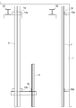
- FIG. 3 is an upper side view showing the first car guide rail 5 and the first counterweight guide rail 7 respectively installed in the hoistway 1 of FIG.
- the first car guide rail 5 is installed in the hoistway 1 by a plurality of rail brackets 14, and the first counterweight guide rail 7 is installed in the hoistway 1 by a plurality of rail brackets 15.
- the first car guide rail 6 is also installed in the hoistway 1 by a plurality of rail brackets (the rail installation process).
- the hoisting machine 9 is attached to the hoisting machine base 10, and the hoisting machine 9 is attached to the hoisting machine base 10 so that the position is lower than the installation position.
- the hoisting machine 9 and the hoisting machine base 10 are raised by two hoisting machines to the switching position.
- a chain block or the like is used as the lifting machine.
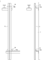
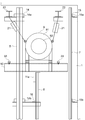
- FIG. 4 is an upper side view showing a state in which the hoisting machine 9 attached to the hoisting machine base 10 of FIG. 2 is suspended by two hoisting machines.
- Two lifting machines 21 are attached to two lifting beams 22 fixed to the top of the hoistway 1.
- two eyebolts 23 each having a ring at the head are fixed to the hoisting machine main body 91 of the hoisting machine 9. The position of each eyebolt 23 is higher than the position of the center of gravity of the hoisting machine 9.
- the hoisting machine 9 is lifted by each hoisting machine 21 in a state where the hook of the moving chain of each hoisting machine 21 is connected to each eyebolt 23 of the hoisting machine 9.
- the hoisting machine base 10 When the hoisting machine 9 and the hoisting machine base 10 reach the switching position, the hoisting machine base 10 is temporarily placed on a temporary placing table fixed in the hoistway 1. At this time, the side surface of the hoisting machine base 10 is opposed to the back surface of the flange portion of the first car guide rail 5, and the end of the hoisting machine base 10 is the end face of the guide portion of the first counterweight guide rail 7. To face.
- the rail bracket 14b at the second stage from the top of the plurality of rail brackets 14 holding the first car guide rail 5 serves as a temporary mounting base (the switching position raising step).
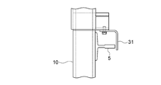
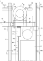
- FIG. 5 shows a state in which the car rail side guide member 31 and the weight rail side guide member 32 of FIG. 4 are attached to the hoisting machine base 10 and the moving chains of the two lifting machines 21 are connected to the hoisting machine base 10.
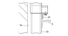
- FIG. FIG. 6 is a cross-sectional view taken along line VI-VI in FIG. 7 is an enlarged view showing the car rail side guide member 31 of FIG.
- the car rail side guide member 31 is fixed to the hoisting machine base 10 with, for example, bolts in a state of facing the front surface of the flange portion of the first car guide rail 5.
- the flange portion of the first car guide rail 5 is sandwiched between the hoisting machine base 10 and the car rail side guide member 31 in the thickness direction of the flange portion of the first car guide rail 5.
- the side surface of the hoisting machine base 10 and the car rail side guide member 31 can slide on the flange portion of the first car guide rail 5.
- the weight rail side guide member 32 is a plate-like member arranged horizontally. As shown in FIG. 6, the weight rail side guide member 32 is provided with a recess 32 a into which the guide portion of the first counterweight guide rail 7 is inserted.
- the weight rail side guide member 32 is fixed to the hoisting machine base 10 with, for example, a bolt in a state where the guide portion of the first counterweight guide rail 7 is inserted into the recess 32a. Thereby, the weight rail side guide member 32 can slide on the guide portion of the first counterweight guide rail 7 on the inner surface of the recess 32a.
- Two eye bolts 33 with a ring on the head are fixed to the upper surface of the hoisting machine base 10.
- the two eyebolts 33 are arranged on both sides of the hoisting machine 9 in the width direction.
- the moving chain of each lifting machine 21 is connected from the two eyebolts 23 fixed to the hoisting machine 9 to the two eyebolts 33 fixed to the hoisting machine base 10.
- the moving chain is connected from the hoisting machine 9 to the hoisting machine base 10.
- the hoisting machine base 10 is hung by two lifting machines 21 with the hoisting machine 9 attached to the hoisting machine base 10, and the hoisting machine 9 and the hoisting machine base 10 are installed from the switching position to the installation position. Is raised by each lifting machine 21.
- the hoisting machine base 10 is guided to the first car guide rail 5 by the car rail side guide member 31, and ascends while being guided to the first counterweight guide rail 7 by the weight rail side guide member 32. . That is, the hoisting machine base 10 is guided to the first car guide rail 5 in a state where the flange portion of the first car guide rail 5 is sandwiched between the hoisting machine base 10 and the car rail side guide member 31.
- the first counterweight guide rail 7 is guided to the first counterweight guide rail 7 in a state where the guide portion of the first counterweight guide rail 7 is inserted into the recess 32 a of the weight rail side guide member 32.
- the hoisting machine base 10 When the hoisting machine base 10 is guided by the first car guide rail 5, the hoisting machine base 10 contacts the back surface of the flange portion of the first car guide rail 5, and the hoisting machine base 10 is in contact with the first car guide rail 5.
- the guide portion of the first counterweight guide rail 7 contacts the inner surface of the recess 32 a of the weight rail side guide member 32. Thereby, the hoisting machine 9 and the hoisting machine stand 10 rise stably (the above, the raising process for installation positions).
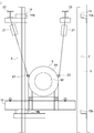
- FIG. 8 is an upper side view showing a state in which the hoisting machine 9 and the hoisting machine base 10 of FIG. 5 are in the installation position.
- the first support fixing member 12 that receives the hoisting machine base 10 from below is provided.
- a support fixing member 13 that receives the hoisting machine base 10 from below is fixed to the first counterweight guide rail 7 while being fixed to the car guide rail 5, and the hoisting machine base 10 is attached to each of the support fixing members 12 and 13. For example, it is fixed with a bolt.
- the hoisting machine 9 and the hoisting machine base 10 are supported by the first car guide rail 5 and the first counterweight guide rail 7 in a state where the hoisting machine 9 and the hoisting machine base 10 are disposed at the installation positions (referred to above as the winding machine). Upper machine support process).
- the second counterweight guide rail 8 that has not been installed in the above-described rail installation process is installed below the installation positions of the hoisting machine 9 and the hoisting machine base 10. To do. At this time, the second counterweight guide rail 8 is installed by the plurality of rail brackets 16 (the additional rail installation step).
- the upper end portion of the second counterweight guide rail 8 and the hoisting machine base 10 are connected by the support fixing member 11.
- the height dimension of the support fixing member 11 is adjusted by adjusting the number of the spacers 11 b of the support fixing member 11, and the space between the upper end portion of the second counterweight guide rail 8 and the hoisting machine base 10 is adjusted.
- the support fixing member 11 is interposed between the two.
- the support fixing member 11 is fixed to each of the upper end portion of the second counterweight guide rail 8 and the hoisting machine base 10 with, for example, bolts.
- the hoisting machine 9 and the hoisting machine base 10 are supported not only by the first car guide rail 5 and the first counterweight guide rail 7 but also by the second counterweight guide rail 8 ( The connection process).
- the two lifting machines 21 are removed (lifting machine removal process).
- the hoisting machine 9 and the hoisting machine base 10 are installed at the installation position in the hoistway 1.
- the car 2 provided with a pair of car suspension cars is disposed between the first and second car guide rails 5 and 6, and the counterweight 3 provided with the counterweight suspension car 17 is provided as the first.
- the second counterweight guide rails 7 and 8, and the ropes 18 are sequentially wound around the pair of car suspension wheels, the driving sheave 92, and the counterweight suspension wheel 17 from the car side main rope end device.
- the car 2 and the counterweight 3 are suspended by the ropes 18 by connecting to the weight side main rope end device.
- an elevator apparatus is manufactured.
- the hoisting machine base 10 is hung by the lifting machine 21 with the hoisting machine 9 attached to the hoisting machine base 10, and the first car guide rail 5 and the first car
- the hoisting machine 9 and the hoisting machine base 10 are raised to the installation position while guiding the hoisting machine base 10 to the counterweight guide rail 7 of the counterweight, so that the first and second counterweight guides that oppose each other.
- the hoisting machine 9 and the hoisting machine base 10 can be transported by the lifting machine 21 to an installation position outside the range between the rails 7 and 8, that is, an installation position located above the second counterweight guide rail 8. it can.
- the range which conveys the hoisting machine 9 and the hoisting machine base 10 with the lifting machine 21 can be expanded, and the freedom degree of the installation position of the hoisting machine 9 and the hoisting machine base 10 can be improved.
- the hoisting machine 9 and the hoisting machine base 10 can be easily installed at the installation position.
- the second balance is provided below the hoisting machine 9 and the hoisting machine base 10 arranged at the installation position. Since the additional rail installation process for installing the weight guide rail 8 is performed, the hoisting machine 9 and the hoisting machine base 10 are raised without the second counterweight guide rail 8 being in the way in the installation position raising process. It is possible to improve the working efficiency in the ascending process for the installation position.
- the first car guide rail 5 is wound around the first car guide rail 5 in a state where the flange portion of the first car guide rail 5 is sandwiched between the car rail side guide member 31 and the hoisting machine base 10. Since the upper machine base 10 is guided, even if the direction of the guide portion of the first car guide rail 5 is different from the direction of the guide portion of the first counterweight guide rail 7, the first counterweight The hoisting machine base 10 can be stably guided by the guide rail 7 and the first car guide rail 5.
- the hoisting machine 9 and the hoisting machine 9 are hung by the lifting machine 21 with the hoisting machine 9 attached to the hoisting machine base 10 and moved to a switching position that is lower than the installation position. Since the lifting machine 21 is connected from the hoisting machine 9 to the hoisting machine stage 10 after the raising process for the switching position for raising the platform 10, the lifting machine 21 moves to the switching position close to the installation position in the hoistway 1.
- the hoisting machine 9 and the hoisting machine base 10 can be raised in a state where the position of the suspension point is higher than the position of the center of gravity of the hoisting machine 9 and the hoisting machine base 10.
- the hoisting machine 9 and the hoisting machine base 10 can be stably and easily carried to the switching position, and the work of raising the hoisting machine 9 and the hoisting machine base 10 by the lifting machine 21 is performed more efficiently. be able to.
- the rail bracket 14b that holds the first car guide rail 5 is used as a temporary table on which the hoisting machine base 10 is placed in the switching position raising step.
- the present invention is not limited to this.
- a hoisting machine base 10 may be mounted.
- FIG. FIG. 9 shows an elevator hoist installation method according to Embodiment 2 of the present invention, in which a car rail side guide member 31 and a weight rail side guide member 32 are attached to the hoisting machine base 10 and two lifting machines 21 are attached.
- FIG. 3 is an upper side view showing a state in which the moving chain is connected to the hoisting machine base 10.
- FIG. 10 is a sectional view taken along line XX of FIG.
- FIG. 11 is an enlarged view showing the car rail side guide member 31 of FIG.
- the procedure for installing the hoisting machine 9 and the hoisting machine base 10 in the present embodiment at the installation position is the same as that of the first embodiment.
- the configuration of the car rail side guide member 31 is different from that of the first embodiment.
- the car rail side guide member 31 when the car rail side guide member 31 is attached to the hoisting machine base 10 in the guide member attaching process, the side surface of the hoisting machine base 10 is opposed to the back surface of the flange portion of the first car guide rail 5, and the car rail side With the guide member 31 opposed to the end face of the guide portion of the first car guide rail 5, the car rail side guide member 31 is fixed to the hoisting machine base 10 with, for example, bolts. As a result, the first car guide rail 5 is sandwiched between the hoisting machine base 10 and the car rail side guide member 31. Further, the hoisting machine base 10 can slide on the back surface of the first car guide rail 5, and the car rail side guide member 31 can slide on the end surface of the guide portion of the first car guide rail 5.
- the side surface of the hoisting machine base 10 is opposed to the back surface of the flange portion of the first car guide rail 5, and the car rail side guide member 31 is moved to the first car guide rail. 5 with the first car guide rail 5 sandwiched between the hoisting machine base 10 and the car rail side guide member 31 so as to face the end surface of the guide portion 5.
- the hoisting machine base 10 is moved to the first counterweight with the guide portion of the first counterweight guide rail 7 being inserted into the concave portion 32a of the weight rail side guide member 32.
- Guide the guide rail 7. Other configurations and procedures are the same as those in the first embodiment.
- the side surface of the hoisting machine base 10 is opposed to the back surface of the flange portion of the first car guide rail 5, and the car rail side guide member 31 is moved to the first car guide rail 5. Since the hoisting machine base 10 is guided to the first car guide rail 5 in a state of being opposed to the end face of the guide part, the direction of the guide part of the first car guide rail 5 is the first counterweight. Even if the direction of the guide portion of the guide rail 7 is different, the hoisting machine base 10 can be stably guided by the first counterweight guide rail 7 and the first car guide rail 5.
- FIG. 12 shows a first car guide rail 5 and a first counterweight guide rail 7 which are respectively installed in the hoistway 1 in the rail installation process of the elevator hoist installation method according to Embodiment 3 of the present invention.
- FIG. 6 is an upper side view showing the second counterweight guide rail 8.
- the second counterweight guide rail 8 is not installed in the hoistway 1, but in the rail installation process of the present embodiment, as shown in FIG. Not only the first car guide rail 5, the second car guide rail 6, and the first counterweight guide rail 7 but also the second counterweight guide rail 8 is installed in the hoistway 1 (the rail Installation process).
- the hoisting machine 9 is attached to the hoisting machine base 10, and the hoisting machine 9 is attached to the hoisting machine base 10 in the same manner as the switching position raising step in the first embodiment.
- the hoisting machine 9 and the hoisting machine base 10 are raised by the two lifting machines 21 to a switching position having a height lower than the installation position.
- FIG. 13 is an upper side view showing a state in which the hoisting machine 9 is suspended by two lifting machines 21 at the switching position in the switching position raising step of the elevator hoisting machine installation method according to Embodiment 3 of the present invention.
- FIG. 13 In the raising step for the switching position, when the hoisting machine 9 and the hoisting machine base 10 reach the switching position, the hoisting machine base is attached to the rail fixing portion 11a fixed to the upper end portion of the second counterweight guide rail 8. The hoisting machine 9 and the hoisting machine base 10 are temporarily supported by the second counterweight guide rail 8. Therefore, in this example, the rail fixing part 11a is a temporary table fixed in the hoistway 1 (the above is a switching position ascending step).
- the same car rail side guide member 31 and weight rail side guide member 32 as in the first embodiment are attached to the hoisting machine base 10 and the moving chains of the two lifting machines 21 are hoisted.
- the machine 9 is connected to the hoisting machine base 10.
- FIG. 14 shows a state where the car rail side guide member 31 and the weight rail side guide member 32 are attached to the hoisting machine base 10 of FIG. 13 and the moving chains of the two lifting machines 21 are connected to the hoisting machine base 10.
- FIG. The car rail side guide member 31 and the weight rail side guide member 32 are in the state in which the hoisting machine base 10 is placed on the rail fixing part 11a fixed to the upper end part of the second counterweight guide rail 8. 1 is fixed to the hoisting machine base 10 with bolts, for example.
- the moving chains of the two lifting machines 21 are also in the state in which the hoisting machine base 10 is mounted on the rail fixing part 11a fixed to the upper end part of the second counterweight guide rail 8 and the first embodiment.
- the hoisting machine 9 is connected to the hoisting machine base 10 (the guide member attaching step).
- the hoisting machine base 10 is hung by two hoisting machines 21 with the hoisting machine 9 attached to the hoisting machine base 10, and each lifting machine is moved from the switching position to the installation position.
- the hoisting machine 9 and the hoisting machine base 10 are raised by the heavy machine 21.
- the hoisting machine base 10 is separated upward from the rail fixing part 11a fixed to the upper end of the second counterweight guide rail 8, and a space is formed between the hoisting machine base 10 and the rail fixing part 11a. This occurs (upward process for the installation position).
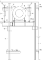
- FIG. 15 is an upper side view showing a state in which the hoisting machine 9 and the hoisting machine base 10 of FIG. 14 are in the installation position.
- the support fixing member 12 is fixed to the first car guide rail 5 and the support fixing member 13 is fixed to the first counterweight guide rail 7 as in the first embodiment.
- the hoisting machine base 10 is fixed to the support fixing members 12 and 13 by, for example, bolts.
- the hoisting machine 9 and the hoisting machine base 10 are supported by the first car guide rail 5 and the first counterweight guide rail 7 in a state where the hoisting machine 9 and the hoisting machine base 10 are disposed at the installation positions (referred to above as the winding machine).
- Upper machine support process ).
- the upper end of the second counterweight guide rail 8 and the hoisting machine base 10 are connected by interposing a connecting column and a spacer in the space between the hoisting machine base 10 and the rail fixing part 11a.
- FIG. 16 shows a state in which a connecting column and a spacer are interposed in the space between the rail fixing portion 11a fixed to the upper end portion of the second counterweight guide rail 8 of FIG. It is an upper side view.
- a connecting column 11c and a plurality of spacers 11b are interposed between the rail fixing portion 11a and the hoisting machine base 10.
- the support fixing member 11 including the rail fixing portion 11 a, the plurality of spacers 11 b, and the connection pillar 11 c is interposed between the upper end portion of the second counterweight guide rail 8 and the hoisting machine base 10.
- the height dimension of the support fixing member 11 is adjusted by adjusting the number of the spacers 11b.
- the connection pillar 11c is fixed to each of the rail fixing part 11a and the hoisting machine base 10 with, for example, bolts.
- the hoisting machine base 10 and the second counterweight guide rail 8 are connected to each other via the support fixing member 11.
- the hoisting machine 9 and the hoisting machine base 10 are supported by the second counterweight guide rail 8 via the support fixing member 11 (the connection process).
- the two lifting machines 21 are removed (lifting machine removing step).
- the hoisting machine 9 and the hoisting machine base 10 are installed at the installation position in the hoistway 1.
- the car 2 provided with a pair of car suspension cars is disposed between the first and second car guide rails 5 and 6, and the counterweight suspension car 17 is provided.
- the counterweight 3 is arranged between the first and second counterweight guide rails 7 and 8, and each rope 18 is connected to the car main rope end device from a pair of car suspension wheels, a driving sheave 92,
- the car 2 and the counterweight 3 are suspended by the ropes 18 by being sequentially wound around the counterweight suspension wheel 17 and connected to the weight side main rope end device.
- an elevator apparatus is manufactured.
- the second counterweight guide is provided below the installation positions of the hoisting machine 9 and the hoisting machine base 10 in the rail installation process prior to the installation position raising process. Since the rail 8 is installed, the second counterweight guide rail 8 can be installed without the hoisting machine 9 and the hoisting machine base 10 getting in the way. The efficiency of installation work can be improved.
- the moving chain of each lifting machine 21 can be connected from the hoisting machine 9 to the hoisting machine base 10, In order to connect the moving chain of each lifting machine 21 from the hoisting machine 9 to the hoisting machine base 10, it is not necessary to provide a dedicated temporary stand on the hoistway 1 on which the hoisting machine base 10 is placed. Can be prevented.
- the hoisting machine base 10 is guided to the first car guide rail 5 with the car rail side guide member 31 facing the front surface of the flange portion of the first car guide rail 5.
- the first car guide rail 5 is wound around the first car guide rail 5 with the car rail side guide member 31 facing the end surface of the guide portion of the first car guide rail 5.
- the upper machine base 10 may be guided.
Abstract
Description
実施の形態1.
図1は、この発明の実施の形態1によるエレベータの巻上機据付方法によって巻上機が据え付けられたエレベータ装置を示す上面図である。また、図2は、図1のかご側から釣合おもり側を見たときのエレベータ装置を示す上部側面図である。図において、昇降路1内には、かご2及び釣合おもり3が昇降可能に設けられている。昇降路1には、昇降路1の幅方向について対向する一対の昇降路壁面1a,1bが形成されている。かご2は、底面、上面、正面、背面及び一対の側面を有している。かご2の一方の側面は、空間を介して一方の昇降路壁面1aに対向しており、かご2の他方の側面は、空間を介して他方の昇降路壁面1bに対向している。かご2の正面には、かご出入口が設けられている。かご2は、上から見たとき、かご出入口を各階の乗場4に向けて配置されている。
図9は、この発明の実施の形態2によるエレベータの巻上機据付方法において、かごレール側ガイド部材31及びおもりレール側ガイド部材32が巻上機台10に取り付けられ、2台の揚重機21の移動チェーンが巻上機台10に繋がっている状態を示す上部側面図である。また、図10は、図9のX-X線に沿った断面図である。さらに、図11は、図10のかごレール側ガイド部材31を示す拡大図である。本実施の形態での巻上機9及び巻上機台10を据付位置に据え付けるときの手順は、実施の形態1と同様である。本実施の形態では、かごレール側ガイド部材31の構成が実施の形態1と異なっている。
図12は、この発明の実施の形態3によるエレベータの巻上機据付方法のレール設置工程で昇降路1内にそれぞれ設置される第1のかごガイドレール5、第1の釣合おもりガイドレール7及び第2の釣合おもりガイドレール8を示す上部側面図である。巻上機9及び巻上機台10を昇降路1内の据付位置に据え付けるときには、まず、第1のかごガイドレール5、第2のかごガイドレール6、第1の釣合おもりガイドレール7及び第2の釣合おもりガイドレール8を昇降路1内に設置する。
Claims (6)
- かご及び釣合おもりと、前記かご及び前記釣合おもりを昇降させる巻上機と、前記巻上機が載せられている巻上機台と、前記かごを案内する第1及び第2のかごガイドレールと、前記釣合おもりを案内する第1及び第2の釣合おもりガイドレールとを有し、前記かご側から前記釣合おもり側を見たとき、前記第1のかごガイドレールと前記第1の釣合おもりガイドレールとの間に前記第2の釣合おもりガイドレールが配置されているエレベータ装置を製造するときに、昇降路内の上部に位置する据付位置に前記巻上機及び前記巻上機台を据え付けるエレベータの巻上機据付方法であって、
前記第1の釣合おもりガイドレール及び前記第1のかごガイドレールを昇降路内に設置するレール設置工程、
前記第1のかごガイドレールに摺動可能なかごレール側ガイド部材と、前記第1の釣合おもりガイドレールに摺動可能なおもりレール側ガイド部材とを前記巻上機台に取り付けるガイド部材取付工程、及び
前記レール設置工程及び前記ガイド部材取付工程の後、前記巻上機を前記巻上機台に取り付けた状態で前記巻上機台を揚重機で吊って、前記第1の釣合おもりガイドレールと前記第1のかごガイドレールとに前記巻上機台を案内させながら、前記据付位置へ前記巻上機及び前記巻上機台を上昇させる据付位置用上昇工程
を備えているエレベータの巻上機据付方法。 - 前記据付位置用上昇工程の後、前記据付位置よりも下方に前記第2の釣合おもりガイドレールを設置する追加レール設置工程、及び
前記追加レール設置工程の後、前記第2の釣合おもりガイドレールの上端部と前記巻上機台とを繋ぐ接続工程
を備えている請求項1に記載のエレベータの巻上機据付方法。 - 前記レール設置工程では、前記据付位置よりも下方に前記第2の釣合おもりガイドレールを設置し、
前記据付位置用上昇工程の後、前記第2の釣合おもりガイドレールの上端部と前記巻上機台とを繋ぐ接続工程
を備えている請求項1に記載のエレベータの巻上機据付方法。 - 前記据付位置用上昇工程では、前記第1のかごガイドレールのフランジ部の背面に前記巻上機台を対向させ、前記第1のかごガイドレールのフランジ部を前記かごレール側ガイド部材と前記巻上機台との間に挟んだ状態で、前記第1のかごガイドレールに前記巻上機台を案内させる請求項1~請求項3のいずれか一項に記載のエレベータの巻上機据付方法。
- 前記据付位置用上昇工程では、前記第1のかごガイドレールのフランジ部の背面に前記巻上機台を対向させ、前記第1のかごガイドレールのガイド部の端面に前記かごレール側ガイド部材を対向させて、前記かごレール側ガイド部材と前記巻上機台との間に前記第1のかごガイドレールを挟んだ状態で、前記第1のかごガイドレールに前記巻上機台を案内させる請求項1~請求項3のいずれか一項に記載のエレベータの巻上機据付方法。
- 前記レール設置工程の後、前記ガイド部材取付工程の前に、前記巻上機を前記巻上機台に取り付けた状態で前記巻上機を前記揚重機で吊って、前記据付位置よりも低い高さに位置する切替位置へ前記巻上機及び前記巻上機台を上昇させる切替位置用上昇工程
を備え、
前記ガイド部材取付工程では、前記巻上機及び前記巻上機台が前記切替位置にある状態で、前記揚重機を前記巻上機から前記巻上機台に繋ぎ代える請求項1~請求項5のいずれか一項に記載のエレベータの巻上機据付方法。
Priority Applications (5)
| Application Number | Priority Date | Filing Date | Title |
|---|---|---|---|
| JP2018518868A JP6537720B2 (ja) | 2016-05-25 | 2016-05-25 | エレベータの巻上機据付方法 |
| PCT/JP2016/065480 WO2017203633A1 (ja) | 2016-05-25 | 2016-05-25 | エレベータの巻上機据付方法 |
| DE112016006907.3T DE112016006907T5 (de) | 2016-05-25 | 2016-05-25 | Installationsverfahren für eine Hebemaschine eines Aufzugs |
| KR1020187032037A KR102106837B1 (ko) | 2016-05-25 | 2016-05-25 | 엘리베이터의 권상기 설치 방법 |
| CN201680085881.9A CN109153539B (zh) | 2016-05-25 | 2016-05-25 | 电梯的曳引机安装方法 |
Applications Claiming Priority (1)
| Application Number | Priority Date | Filing Date | Title |
|---|---|---|---|
| PCT/JP2016/065480 WO2017203633A1 (ja) | 2016-05-25 | 2016-05-25 | エレベータの巻上機据付方法 |
Publications (1)
| Publication Number | Publication Date |
|---|---|
| WO2017203633A1 true WO2017203633A1 (ja) | 2017-11-30 |
Family
ID=60411257
Family Applications (1)
| Application Number | Title | Priority Date | Filing Date |
|---|---|---|---|
| PCT/JP2016/065480 WO2017203633A1 (ja) | 2016-05-25 | 2016-05-25 | エレベータの巻上機据付方法 |
Country Status (5)
| Country | Link |
|---|---|
| JP (1) | JP6537720B2 (ja) |
| KR (1) | KR102106837B1 (ja) |
| CN (1) | CN109153539B (ja) |
| DE (1) | DE112016006907T5 (ja) |
| WO (1) | WO2017203633A1 (ja) |
Cited By (3)
| Publication number | Priority date | Publication date | Assignee | Title |
|---|---|---|---|---|
| JP2019137511A (ja) * | 2018-02-09 | 2019-08-22 | フジテック株式会社 | エレベータ |
| WO2020194523A1 (ja) * | 2019-03-26 | 2020-10-01 | 三菱電機株式会社 | エレベータ装置及びその機械台 |
| JP7424529B1 (ja) | 2023-03-23 | 2024-01-30 | 三菱電機ビルソリューションズ株式会社 | エレベータの据付治具およびエレベータの据付治具の据付方法 |
Families Citing this family (2)
| Publication number | Priority date | Publication date | Assignee | Title |
|---|---|---|---|---|
| CN110697545A (zh) * | 2019-10-10 | 2020-01-17 | 奥帝亚电梯有限公司 | 一种施工升降机及其安装方法 |
| JP7004407B1 (ja) * | 2020-08-14 | 2022-01-21 | 東芝エレベータ株式会社 | 据付治具を備えた巻上機ユニット及びその据付方法 |
Citations (4)
| Publication number | Priority date | Publication date | Assignee | Title |
|---|---|---|---|---|
| WO2008041266A1 (en) * | 2006-09-29 | 2008-04-10 | Mitsubishi Electric Corporation | Elevator device |
| JP2011132012A (ja) * | 2009-12-25 | 2011-07-07 | Toshiba Elevator Co Ltd | エレベータ巻き上げ機の据え付け方法 |
| JP2013245033A (ja) * | 2012-05-23 | 2013-12-09 | Toshiba Elevator Co Ltd | 巻上機据付方法 |
| WO2016024347A1 (ja) * | 2014-08-13 | 2016-02-18 | 三菱電機株式会社 | エレベータの巻上機用機械台取付装置 |
Family Cites Families (7)
| Publication number | Priority date | Publication date | Assignee | Title |
|---|---|---|---|---|
| EP1405812B1 (en) | 2001-03-29 | 2008-02-20 | Mitsubishi Denki Kabushiki Kaisha | Method for installing hoist |
| KR100500861B1 (ko) * | 2002-11-18 | 2005-07-14 | 미쓰비시덴키 가부시키가이샤 | 권양기의 설치방법 |
| CN1990371B (zh) * | 2005-12-27 | 2010-07-21 | 上海三菱电梯有限公司 | 电梯安装的方法及其所用的升降系统 |
| JP2007210708A (ja) | 2006-02-07 | 2007-08-23 | Hitachi Building Systems Co Ltd | エレベータ巻上機の揚重装置及び揚重方法。 |
| JP5595788B2 (ja) * | 2010-05-17 | 2014-09-24 | 東芝エレベータ株式会社 | エレベータのリニューアル方法 |
| JP5805212B2 (ja) | 2011-12-07 | 2015-11-04 | 三菱電機株式会社 | エレベータ装置 |
| CN104428235A (zh) * | 2012-07-04 | 2015-03-18 | 三菱电机株式会社 | 电梯装置 |
-
2016
- 2016-05-25 CN CN201680085881.9A patent/CN109153539B/zh active Active
- 2016-05-25 WO PCT/JP2016/065480 patent/WO2017203633A1/ja active Application Filing
- 2016-05-25 JP JP2018518868A patent/JP6537720B2/ja not_active Expired - Fee Related
- 2016-05-25 KR KR1020187032037A patent/KR102106837B1/ko active IP Right Grant
- 2016-05-25 DE DE112016006907.3T patent/DE112016006907T5/de not_active Withdrawn
Patent Citations (4)
| Publication number | Priority date | Publication date | Assignee | Title |
|---|---|---|---|---|
| WO2008041266A1 (en) * | 2006-09-29 | 2008-04-10 | Mitsubishi Electric Corporation | Elevator device |
| JP2011132012A (ja) * | 2009-12-25 | 2011-07-07 | Toshiba Elevator Co Ltd | エレベータ巻き上げ機の据え付け方法 |
| JP2013245033A (ja) * | 2012-05-23 | 2013-12-09 | Toshiba Elevator Co Ltd | 巻上機据付方法 |
| WO2016024347A1 (ja) * | 2014-08-13 | 2016-02-18 | 三菱電機株式会社 | エレベータの巻上機用機械台取付装置 |
Cited By (3)
| Publication number | Priority date | Publication date | Assignee | Title |
|---|---|---|---|---|
| JP2019137511A (ja) * | 2018-02-09 | 2019-08-22 | フジテック株式会社 | エレベータ |
| WO2020194523A1 (ja) * | 2019-03-26 | 2020-10-01 | 三菱電機株式会社 | エレベータ装置及びその機械台 |
| JP7424529B1 (ja) | 2023-03-23 | 2024-01-30 | 三菱電機ビルソリューションズ株式会社 | エレベータの据付治具およびエレベータの据付治具の据付方法 |
Also Published As
| Publication number | Publication date |
|---|---|
| JPWO2017203633A1 (ja) | 2018-09-20 |
| KR102106837B1 (ko) | 2020-05-07 |
| DE112016006907T5 (de) | 2019-02-14 |
| CN109153539A (zh) | 2019-01-04 |
| JP6537720B2 (ja) | 2019-07-03 |
| CN109153539B (zh) | 2020-03-03 |
| KR20180132821A (ko) | 2018-12-12 |
Similar Documents
| Publication | Publication Date | Title |
|---|---|---|
| WO2017203633A1 (ja) | エレベータの巻上機据付方法 | |
| JP5951104B2 (ja) | エレベータの改修方法 | |
| JP6579736B2 (ja) | 機械室レスエレベータの改修方法及び機械室レスエレベータ | |
| JP6969686B2 (ja) | 工事用エレベーターの揚程延長方法 | |
| JP2007210703A (ja) | マシンルームレスエレベータの巻上機据付装置および据付工法 | |
| JP5693723B2 (ja) | ダブルデッキエレベータ | |
| JP2015151230A (ja) | エレベータ用主ロープ振れ止め装置 | |
| CN110709344B (zh) | 电梯 | |
| JP6336225B2 (ja) | エレベータ装置 | |
| JP4091326B2 (ja) | エレベーター装置 | |
| JP2008285260A (ja) | 機械室レスエレベータのガイドレール据え付け工法 | |
| JP6567143B2 (ja) | エレベータ装置 | |
| JP6261418B2 (ja) | エレベータの釣合おもり装置及びその改修方法 | |
| JPWO2018198232A1 (ja) | エレベータ装置 | |
| JP6818909B2 (ja) | 機械室レスエレベータ | |
| JP6605411B2 (ja) | 揚重ブラケット及び巻上機 | |
| CN108883897B (zh) | 电梯装置 | |
| JP4312590B2 (ja) | エレベータ上部機器の下部組立て工法 | |
| JP2016008131A (ja) | エレベーター及び既設エレベーターの改造方法 | |
| JP5930842B2 (ja) | エレベータの据付方法及び据付用治具 | |
| WO2020194523A1 (ja) | エレベータ装置及びその機械台 | |
| EP1717184B1 (en) | Elevator | |
| JP5058181B2 (ja) | エレベータのロープ掛け方法 | |
| JP5570602B2 (ja) | エレベータ装置 | |
| WO2023175881A1 (ja) | 巻上機の据付方法 |
Legal Events
| Date | Code | Title | Description |
|---|---|---|---|
| ENP | Entry into the national phase |
Ref document number: 2018518868 Country of ref document: JP Kind code of ref document: A |
|
| ENP | Entry into the national phase |
Ref document number: 20187032037 Country of ref document: KR Kind code of ref document: A |
|
| 121 | Ep: the epo has been informed by wipo that ep was designated in this application |
Ref document number: 16903115 Country of ref document: EP Kind code of ref document: A1 |
|
| 122 | Ep: pct application non-entry in european phase |
Ref document number: 16903115 Country of ref document: EP Kind code of ref document: A1 |