WO2017199620A1 - Structure de connexion de borne pour bloc-batterie - Google Patents
Structure de connexion de borne pour bloc-batterie Download PDFInfo
- Publication number
- WO2017199620A1 WO2017199620A1 PCT/JP2017/014273 JP2017014273W WO2017199620A1 WO 2017199620 A1 WO2017199620 A1 WO 2017199620A1 JP 2017014273 W JP2017014273 W JP 2017014273W WO 2017199620 A1 WO2017199620 A1 WO 2017199620A1
- Authority
- WO
- WIPO (PCT)
- Prior art keywords
- bus bar
- bolt
- notch
- nut
- terminal block
- Prior art date
Links
Images


Classifications
-
- H—ELECTRICITY
- H01—ELECTRIC ELEMENTS
- H01M—PROCESSES OR MEANS, e.g. BATTERIES, FOR THE DIRECT CONVERSION OF CHEMICAL ENERGY INTO ELECTRICAL ENERGY
- H01M50/00—Constructional details or processes of manufacture of the non-active parts of electrochemical cells other than fuel cells, e.g. hybrid cells
- H01M50/50—Current conducting connections for cells or batteries
-
- H—ELECTRICITY
- H01—ELECTRIC ELEMENTS
- H01M—PROCESSES OR MEANS, e.g. BATTERIES, FOR THE DIRECT CONVERSION OF CHEMICAL ENERGY INTO ELECTRICAL ENERGY
- H01M50/00—Constructional details or processes of manufacture of the non-active parts of electrochemical cells other than fuel cells, e.g. hybrid cells
- H01M50/20—Mountings; Secondary casings or frames; Racks, modules or packs; Suspension devices; Shock absorbers; Transport or carrying devices; Holders
- H01M50/204—Racks, modules or packs for multiple batteries or multiple cells
- H01M50/207—Racks, modules or packs for multiple batteries or multiple cells characterised by their shape
- H01M50/209—Racks, modules or packs for multiple batteries or multiple cells characterised by their shape adapted for prismatic or rectangular cells
-
- H—ELECTRICITY
- H01—ELECTRIC ELEMENTS
- H01M—PROCESSES OR MEANS, e.g. BATTERIES, FOR THE DIRECT CONVERSION OF CHEMICAL ENERGY INTO ELECTRICAL ENERGY
- H01M50/00—Constructional details or processes of manufacture of the non-active parts of electrochemical cells other than fuel cells, e.g. hybrid cells
- H01M50/20—Mountings; Secondary casings or frames; Racks, modules or packs; Suspension devices; Shock absorbers; Transport or carrying devices; Holders
- H01M50/262—Mountings; Secondary casings or frames; Racks, modules or packs; Suspension devices; Shock absorbers; Transport or carrying devices; Holders with fastening means, e.g. locks
-
- H—ELECTRICITY
- H01—ELECTRIC ELEMENTS
- H01M—PROCESSES OR MEANS, e.g. BATTERIES, FOR THE DIRECT CONVERSION OF CHEMICAL ENERGY INTO ELECTRICAL ENERGY
- H01M50/00—Constructional details or processes of manufacture of the non-active parts of electrochemical cells other than fuel cells, e.g. hybrid cells
- H01M50/20—Mountings; Secondary casings or frames; Racks, modules or packs; Suspension devices; Shock absorbers; Transport or carrying devices; Holders
- H01M50/296—Mountings; Secondary casings or frames; Racks, modules or packs; Suspension devices; Shock absorbers; Transport or carrying devices; Holders characterised by terminals of battery packs
-
- Y—GENERAL TAGGING OF NEW TECHNOLOGICAL DEVELOPMENTS; GENERAL TAGGING OF CROSS-SECTIONAL TECHNOLOGIES SPANNING OVER SEVERAL SECTIONS OF THE IPC; TECHNICAL SUBJECTS COVERED BY FORMER USPC CROSS-REFERENCE ART COLLECTIONS [XRACs] AND DIGESTS
- Y02—TECHNOLOGIES OR APPLICATIONS FOR MITIGATION OR ADAPTATION AGAINST CLIMATE CHANGE
- Y02E—REDUCTION OF GREENHOUSE GAS [GHG] EMISSIONS, RELATED TO ENERGY GENERATION, TRANSMISSION OR DISTRIBUTION
- Y02E60/00—Enabling technologies; Technologies with a potential or indirect contribution to GHG emissions mitigation
- Y02E60/10—Energy storage using batteries
Definitions
- One aspect of the present invention relates to a terminal connection structure of a battery pack.
- the terminal connection structure of the battery pack described in Patent Literature 1 includes a relay bus bar that connects the electrode terminal of the battery cell and the output line.
- the relay bus bar is bent.
- a through hole through which the set screw of the electrode terminal passes is provided on one end side of the relay bus bar, and a through hole through which a set screw screwed into a nut fixed to the end plate is provided on the other end side of the relay bus bar. It has been.
- the first bolt fixed to the first terminal block and the second bolt fixed to the second terminal block may be connected by the bus bar.
- the through holes through which the first bolt and the second bolt pass are respectively provided at both ends as in the prior art.
- a bent bus bar is used.
- An object of one aspect of the present invention is to provide a battery pack terminal connection structure that can improve assemblability of a bus bar when bolts having different axial directions are connected by a bent bus bar.
- a battery pack terminal connection structure includes a first terminal block to which a first bolt is fixed, a second terminal block to which a second bolt having a different axial direction from the first bolt is fixed, A bent bus bar that connects the first bolt and the second bolt, a first nut that is screwed to the first bolt, and that fastens one end of the bus bar to the first terminal block, and a second bolt that is screwed. And a second nut for fastening the other end of the bus bar to the second terminal block.
- a hole through which the first bolt is inserted is provided at one end of the bus bar, and the other end of the bus bar is provided at the other end. The other end of the bus bar is provided with a notch through which the second bolt is inserted.
- the bus bar can be assembled to the first terminal block and the second terminal block from one direction. Therefore, when connecting the 1st volt
- the second nut is in contact with the bus bar and the other end of the bus bar is tightened against the second terminal block.
- the second bolt has a contact area between the second nut and the bus bar that is loosened by the second nut. It may be arranged between a first position spaced from the bottom of the notch and a second position in contact with the bottom of the notch so as to have a minimum value that does not cause the.
- the second bolt is disposed between the first position and the second position, it is possible to widen a range in which a part tolerance is allowed in the notch portion of the bus bar.
- the first position is a position spaced from the bottom of the notch so that the contact area between the second nut and the bus bar is a minimum value that does not cause loosening of the tightening of the bus bar by the second nut. For this reason, the contact area between the second nut and the bus bar is always equal to or greater than the minimum value.
- the second position is a position where the second bolt comes into contact with the bottom of the notch. For this reason, it becomes possible to prevent the bus bar from being assembled to the first terminal block and the second terminal block.
- the bottom surface of the notch has a semicircular cross section, and the intermediate position between the first position and the second position is the center of a virtual circle virtually formed by the bottom surface of the notch when viewed from the axial direction of the second bolt. It may be offset to the open side of the notch.
- the bus bar is further provided with another bus bar connected to the second bolt in a state of being superimposed on the bus bar, and the other bus bar is provided with a hole through which the second bolt is inserted. You may clamp
- the second nut contacts another bus bar having a hole, and does not contact a bus bar having a notch. Therefore, even if the second bolt is arranged away from the bottom of the notch, a contact area between the second nut and the other bus bar is ensured, so that the other end side of the bus bar is inserted through the other bus bar by the second nut. And securely tightened against the second terminal block. Thus, even if the second bolt is arranged away from the bottom of the notch, there is no particular problem, so that the range for allowing the component tolerance in the notch of the bus bar can be sufficiently widened.
- a battery pack terminal connection structure capable of improving the assemblability of a bus bar when bolts having different axial directions are connected by a bent bus bar.
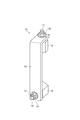
- FIG. 1 is a schematic side view showing a battery pack provided with a terminal connection structure according to an embodiment.
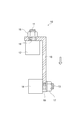
- FIG. 2 is a perspective view showing a terminal connection structure according to an embodiment.
- FIG. 3 is a cross-sectional view of the terminal connection structure shown in FIG.
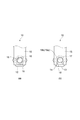
- FIG. 4A is a plan view showing a part on one end side of the bus bar in the terminal connection structure
- FIG. 4B is a front view showing a part on the other end side of the bus bar in the terminal connection structure.
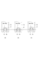
- FIG. 5A is a front view showing a state where the bolt is in a design position slightly spaced from the bottom of the notch
- FIG. 5B is a position where the bolt is on the open side of the notch from the design position.
- FIG. 5A is a front view showing a state where the bolt is in a design position slightly spaced from the bottom of the notch
- FIG. 5B is a position where the bolt is on the open side of the notch from the design position.
- FIG. 5C is a front view showing a state in which the bolt is on the bottom side of the notch portion with respect to the design position.
- FIG. 6 is a conceptual diagram showing the design position of the bolt with respect to the notch of the bus bar.
- FIG. 7 is a cross-sectional view showing an example of a conventional terminal connection structure.
- FIG. 8 is a cross-sectional view showing a part of a terminal connection structure according to another embodiment.
- FIG. 9 is a plan view showing a portion excluding the nut in the terminal connection structure shown in FIG.
- FIG. 10 is a diagram for explaining a modification of the terminal connection structure.
- FIG. 11 is a diagram for explaining a modification of the terminal connection structure.
- FIG. 12 is a diagram for explaining a modification of the terminal connection structure.
- FIG. 13 is a diagram for explaining a modification of the terminal connection structure.
- FIG. 14 is a diagram for explaining a modification of the terminal connection structure.
- FIG. 1 is a schematic side view showing a battery pack provided with a terminal connection structure according to an embodiment.
- the battery pack 1 includes a rectangular parallelepiped housing 2 and a battery module 3 accommodated in the housing 2.
- Connector terminals 4 ⁇ / b> A and 4 ⁇ / b> B are attached to the upper surface of the housing 2.
- the connector terminal 4A is a positive connector terminal
- the connector terminal 4B is a negative connector terminal.
- the battery module 3 has a plurality of batteries 5 such as a plurality of lithium ion secondary batteries arranged in one direction, although not specifically described in detail.
- Each battery 5 is provided with electrode terminals 6A and 6B.
- the electrode terminal 6A is a positive electrode terminal
- the electrode terminal 6B is a positive electrode terminal.
- the battery pack 1 includes terminal connection units 7A and 7B for connecting the connector terminals 4A and 4B and the electrode terminals 6A and 6B, respectively.
- the terminal connection units 7A and 7B have a terminal connection structure according to an embodiment of the present invention.
- a case where the terminal connection structure according to one embodiment of the present invention is applied to the terminal connection unit 7A will be described as an example.
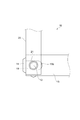
- FIG. 2 is a perspective view showing a terminal connection structure according to an embodiment.
- FIG. 3 is a cross-sectional view of the terminal connection structure shown in FIG. 2 and 3, the terminal connection structure 10 of the present embodiment includes a terminal block 12 (first terminal block) to which a bolt 11 (first bolt) is fixed and a bolt 13 (second bolt) fixed.
- a terminal block 14 (second terminal block), an L-shaped bus bar 15 that connects the bolt 11 and the bolt 13, and a nut 16 that is screwed to the bolt 11 and tightens one end of the bus bar 15 to the terminal block 12 ( A first nut) and a nut 17 (second nut) that is screwed to the bolt 13 and fastens the other end of the bus bar 15 to the terminal block 14.
- the bolts 11 and 13 and the nuts 16 and 17 are made of iron.
- the bus bar 15 is formed of a conductive member such as aluminum, copper, or iron. Thereby, the bolts 11 and 13 are electrically connected via the nut 16, the bus bar 15, and the nut 17.
- the axial direction of the bolt 11 and the axial direction of the bolt 13 are different. Specifically, the axial direction of the bolt 13 is perpendicular to the axial direction of the bolt 11. Accordingly, the bus bar 15 has a bent shape that is bent vertically.
- the bolt 11 is fixed in a state of being embedded in the terminal block 12 so that a part thereof protrudes from the upper surface of the terminal block 12.
- the bolt 13 is fixed in a state of being embedded in the terminal block 14 so that a part thereof protrudes from the upper surface of the terminal block 14.
- the nut 16 fastens one end side of the bus bar 15 to the terminal block 12 while being in contact with the bus bar 15.
- the nut 17 fastens the other end side of the bus bar 15 to the terminal block 14 while being in contact with the bus bar 15.
- the bolt 11 is connected to the connector terminal 4A through at least one other bus bar (not shown).
- the bolt 13 is connected to the electrode terminal 6A via at least one other bus bar (not shown).
- Other bus bars are in contact with the upper surfaces of the terminal blocks 12 and 14.
- a hole 18 having a circular cross section through which the bolt 11 is inserted is provided on one end side of the bus bar 15.
- the outer diameter of the seat surface of the nut 16 is larger than the inner diameter of the hole 18.
- the bottom surface 19a of the notch 19 has a semicircular cross section.
- the outer diameter of the seating surface of the nut 17 is equal to the outer diameter of the seating surface of the nut 16.
- the contact area between the nut 17 and the bus bar 15 is as follows.
- the contact area with 15 is smaller.
- the contact area between the nut 17 and the bus bar 15 varies depending on the positional relationship between the bolt 13 and the notch 19.
- the necessary contact area between the nut 17 and the bus bar 15 is ensured in a state where the bolt 13 is at a design position spaced from the bottom 19 b of the notch 19 by a predetermined amount. Is done.
- FIG. 5B in the state where the bolt 13 is on the open side of the notch 19 with respect to the design position, the contact area between the nut 17 and the bus bar 15 is reduced. A necessary contact area with the bus bar 15 is not ensured. In this case, the contact surface pressure between the nut 17 and the bus bar 15 is increased, and the nut 17 or the bus bar 15 is deformed in a depressed manner, so that the tightening of the bus bar 15 by the nut 17 is loosened.
- the design position of the bolt 13 with respect to the notch portion 19 of the bus bar 15 is the minimum value at which the contact area between the nut 17 and the bus bar 15 does not cause loosening of the tightening of the bus bar 15 by the nut 17.
- the first position where the bolt 13 is separated from the bottom 19b of the notch 19 P position in the figure
- the second position where the bolt 13 contacts the bottom 19b of the notch 19 Q position in the figure. It is set to an intermediate position.
- the contact area between the nut 17 and the bus bar 15 that is the minimum value that does not cause loosening of the bus bar 15 by the nut 17 is appropriately set according to the thickness and material of the bus bar 15, the dimensions of the notch portion 19, and the like.
- the intermediate position between the first position and the second position is offset to the open side of the notch 19 from the center G of the virtual circle X virtually formed by the bottom surface 19a of the notch 19 when viewed from the axial direction of the bolt 13. is doing.
- the center E of the bolt 13 when the bolt 13 is at the design position is located closer to the open side of the notch 19 than the center G of the virtual circle X. It is offset by a fixed amount e.
- the diameter of the virtual circle X is equal to the inner diameter of the hole 18.
- the bottom surface 19a of the notch 19 forms a half of the virtual circle X.
- the bolt 13 has a first position separated from the bottom portion 19b of the notch 19 so that the contact area between the nut 17 and the bus bar 15 becomes a minimum value that does not cause loosening of the tightening of the bus bar 15 by the nut 17, and the notch 19 and the second position where it contacts the bottom 19b.
- the bus bar 15 When the bus bar 15 is assembled to the terminal blocks 12, 14, the bus bar 15 is moved in the axial direction of the bolt 11 (the arrow direction in FIG. 3), so that the bolt 11 is inserted into the hole 18 of the bus bar 15 and the bus bar 15 The bolt 13 is inserted through the notch 19. Then, a nut 16 is screwed into the bolt 11 and one end of the bus bar 15 is fastened to the terminal block 12, and a nut 17 is screwed into the bolt 13 to tighten the other end of the bus bar 15 to the terminal block 14.
- FIG. 7 is a cross-sectional view showing an example of a conventional terminal connection structure.
- the terminal connection structure 50 includes an L-shaped bus bar 51 that connects the bolt 11 and the bolt 13. On both end sides of the bus bar 51, holes 52 and 53 having circular cross sections through which the bolts 11 and 13 are inserted are provided. Other configurations are the same as those of the terminal connection structure 10 described above.
- a hole 18 through which the bolt 11 is inserted is provided on one end side of the bus bar 15, and a notch 19 through which the bolt 13 is inserted is provided on the other end side of the bus bar 15.
- the notch 19 is open to the other end of the bus bar 15.
- the bolt 13 is the first spaced apart from the bottom portion 19b of the notch portion 19 so that the contact area between the nut 17 and the bus bar 15 becomes a minimum value that does not cause loosening of the tightening of the bus bar 15 by the nut 17. It is arranged between the position and the second position that abuts against the bottom 19 b of the notch 19. For this reason, the range which accept
- the first position is a position separated from the bottom portion 19b of the notch portion 19 so that the contact area between the nut 17 and the bus bar 15 becomes a minimum value that does not cause loosening of the tightening of the bus bar 15 by the nut 17.
- the second position is a position where the bolt 13 contacts the bottom 19 b of the notch 19. This prevents the bus bar 15 from being assembled to the terminal blocks 12 and 14.
- the intermediate position between the first position and the second position is notch from the center G of the virtual circle X that is virtually formed by the bottom surface 19a of the notch 19 when viewed from the axial direction of the bolt 13. It is offset to the open side of the part 19. Therefore, since the distance from the intermediate position between the first position and the second position to the first position and the second position becomes longer, the range in which the component tolerance is allowed in the notch portion 19 of the bus bar 15 can be further increased.
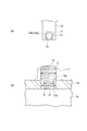
- FIG. 8 is a cross-sectional view showing a part of a terminal connection structure according to another embodiment of the present invention.
- FIG. 9 is a plan view showing a portion excluding the nut in the terminal connection structure shown in FIG. 8 and 9, one end side of the bus bar 20 is connected to the bolt 13.
- the bus bar 20 is connected to the bolt 13 while being superimposed on the bus bar 15. Therefore, the other end side of the bus bar 15 is in contact with the upper surface of the terminal block 14.
- the bus bar 20 extends in a direction perpendicular to the longitudinal direction of the bus bar 15.
- the nut 17 tightens the other end side of the bus bar 15 together with the bus bar 20 in contact with the bus bar 20.
- the nut 17 contacts the bus bar 20 having the hole portion 21 and does not contact the bus bar 15 having the notch portion 19. Therefore, even if the bolt 13 is disposed away from the bottom 19 b of the notch 19, the contact area between the nut 17 and the bus bar 20 is ensured, so that the other end of the bus bar 15 is connected to the terminal via the bus bar 20 by the nut 17. It is securely tightened against the base 14. Thus, even if the bolt 13 is arranged away from the bottom portion 19b of the notch portion 19, there is no particular problem, so that the range in which the component tolerance is allowed in the notch portion 19 of the bus bar 15 can be sufficiently widened.
- the bolt 13 and the notch 19 are deformed. More specifically, the bolt 13 here has a screwing portion 13a having a diameter C equivalent to the diameter of the bolt 13 shown in FIG. 4, and a diameter D smaller than the diameter C of the screwing portion 13a. A reduced diameter portion 13b. The reduced diameter portion 13b is located closer to the terminal block 14 than the screwing portion 13a. That is, here, the terminal 13 side portion of the bolt 13 is relatively thin. The nut 17 is screwed into the screwing portion 13a.
- the dimension A (diameter of the semicircle of the bottom surface 19a) of the cutout portion 19 is larger than the diameter D of the reduced diameter portion 13b and smaller than the diameter C of the screwing portion 13a. . That is, here, the notch 19 is made smaller than that in the above embodiment. In the notch portion 19, a relatively thin reduced diameter portion 13 b of the bolt 13 is disposed. According to this example, the contact area between the bus bar 15 and the nut 17 can be increased, and the assembly intersection can be reduced.
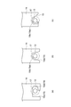
- the notch 19 can be variously modified as shown in FIG.
- the cutout portion 19 includes a portion 19c extending along the longitudinal direction of the bus bar 15, and a portion 19d extending continuously from the portion 19c in the short direction of the bus bar 15. Therefore, it is formed in an L shape.
- the extending direction of the portion 19d is, for example, along the surface direction (the direction along the plate surface) of the portion of the bus bar 15 where the hole 18 is formed. For this reason, for example, when the bus bar 15 rotates along the direction when the nut 16 is screwed into the bolt 11 inserted through the hole 18, the bolt 13 is prevented from contacting the inner surface of the notch 19.
- the notch 19 is formed in a tapered shape. More specifically, here, the cutout portion 19 includes a bottom portion 19b including a bottom surface 19a having a semicircular cross section, and a tapered portion 19e that expands from the bottom portion 19b toward the end of the bus bar 15. In this case, it becomes easy to arrange the bolt 13 in the notch 19.
- the entire extending direction of the notch 19 is inclined with respect to the longitudinal direction of the bus bar 15.
- the extending direction of the notch 19 can be arbitrarily set so that the bolt 13 can be easily disposed in the notch 19.
- the center E of the bolt 13 is positioned with respect to the short direction of the bus bar 15 (the direction in which the notch 19 is passed) in anticipation of a deviation during assembly. It may be offset from the center of the notch 19 by a fixed amount e. In this case, the shift E causes the center E of the bolt 13 to be close to the center of the notch 19, and the reduction of the contact area between the nut 17 and the bus bar 15 can be suppressed. In particular, when the diameter of the seat surface of the nut 17 and the width of the bus bar 15 (dimension in the short direction) are approximately the same, the reduction in the contact area due to the shift in the direction becomes significant. The modified example becomes more effective.
- the axial direction of the bolt 11 and the axial direction of the bolt 13 are orthogonal to each other.
- the shape is not particularly limited, and the axial direction of the bolt 11 and the axial direction of the bolt 13 intersect. If you do.
- the bending angle of the bus bar 15 corresponds to the intersection angle between the axial direction of the bolt 11 and the axial direction of the bolt 13.
- the crossing angle between the axial direction of the bolt 11 and the axial direction of the bolt 13 is smaller than 90 °.
- the bending angle of the bus bar 15 is larger than 90 ° by the difference between the intersection angle and 90 °.
- the intersection angle between the axial direction of the bolt 11 and the axial direction of the bolt 13 and the bending angle of the bus bar 15 may be set independently of each other, and various modifications are possible.
- a plurality of (two here) notches 19 may be provided for a single bus bar 15 (the same applies to the holes 18).
- the notch portion 19 is formed with respect to the hole portion 18 along the surface direction (direction along the plate surface) of the portion where the hole portion 18 is provided in the bus bar 15. May be shifted.
- the bus bar 15 includes a portion 15a in which the hole 18 is provided, a portion 15b extending from the portion 15a in a direction intersecting (orthogonal to) the portion 15a, as in the above embodiment, including.
- the bus bar 15 is formed in an L-shaped plate shape by a portion 15a and a portion 15b. Further, the bus bar 15 includes a portion 15c protruding from the portion 15b along the surface direction of the portion 15a. And the notch part 19 is provided in this part 15c. Thereby, here, the formation position of the notch 19 is shifted with respect to the formation position of the hole 18 along the surface direction of the portion 15a.
- the positional relationship between the hole 18 and the notch 19 can be arbitrarily set according to the manner of assembly.
- the terminal connection structure 10 of the above embodiment is applied to the terminal connection units 7A and 7B that connect the connector terminals 4A and 4B and the electrode terminals 6A and 6B, respectively.
- the present invention is not limited to such a terminal connection unit, and any structure that connects terminals in a battery pack can be applied.
- a battery pack terminal connection structure is provided that can improve the ease of assembling the bus bar when bolts having different axial directions are connected by a bent bus bar.
Landscapes
- Chemical & Material Sciences (AREA)
- Chemical Kinetics & Catalysis (AREA)
- Electrochemistry (AREA)
- General Chemical & Material Sciences (AREA)
- Connection Of Batteries Or Terminals (AREA)
- Battery Mounting, Suspending (AREA)
Abstract
La présente invention porte sur une structure de connexion de borne qui comprend : un premier bloc de borne sur lequel est fixé un premier boulon ; un second bloc de borne sur lequel est fixé un second boulon, le second boulon ayant une direction d'axe différente de celle du premier boulon ; une barre omnibus courbée connectant le premier boulon au second boulon ; un premier écrou vissé sur le premier boulon et fixant un côté d'extrémité de la barre omnibus contre le premier bloc de borne ; et un second écrou vissé sur le second boulon et fixant l'autre côté d'extrémité de la barre omnibus contre le second bloc de borne. Sur le premier côté d'extrémité de la barre omnibus se trouve une partie trou à travers laquelle le premier boulon est inséré. Sur l'autre extrémité de la barre omnibus se trouve une partie découpée qui s'ouvre vers l'autre extrémité de la barre omnibus, et à travers laquelle le second boulon est inséré.
Priority Applications (1)
| Application Number | Priority Date | Filing Date | Title |
|---|---|---|---|
| JP2018518149A JP6729689B2 (ja) | 2016-05-18 | 2017-04-05 | 電池パックの端子接続構造 |
Applications Claiming Priority (2)
| Application Number | Priority Date | Filing Date | Title |
|---|---|---|---|
| JP2016-099648 | 2016-05-18 | ||
| JP2016099648 | 2016-05-18 |
Publications (1)
| Publication Number | Publication Date |
|---|---|
| WO2017199620A1 true WO2017199620A1 (fr) | 2017-11-23 |
Family
ID=60325113
Family Applications (1)
| Application Number | Title | Priority Date | Filing Date |
|---|---|---|---|
| PCT/JP2017/014273 WO2017199620A1 (fr) | 2016-05-18 | 2017-04-05 | Structure de connexion de borne pour bloc-batterie |
Country Status (2)
| Country | Link |
|---|---|
| JP (1) | JP6729689B2 (fr) |
| WO (1) | WO2017199620A1 (fr) |
Citations (6)
| Publication number | Priority date | Publication date | Assignee | Title |
|---|---|---|---|---|
| JPS50139219U (fr) * | 1974-04-30 | 1975-11-17 | ||
| JP2005188945A (ja) * | 2003-12-24 | 2005-07-14 | Auto Network Gijutsu Kenkyusho:Kk | 電圧降下式電流計測装置 |
| JP2006128116A (ja) * | 2004-10-28 | 2006-05-18 | Samsung Sdi Co Ltd | 電池モジュール |
| JP2013041707A (ja) * | 2011-08-12 | 2013-02-28 | Auto Network Gijutsu Kenkyusho:Kk | 電気接続部材 |
| WO2015093564A1 (fr) * | 2013-12-19 | 2015-06-25 | 矢崎総業株式会社 | Module de barre omnibus |
| JP2017027677A (ja) * | 2015-07-16 | 2017-02-02 | 古河電池株式会社 | 蓄電池用接続体 |
Family Cites Families (5)
| Publication number | Priority date | Publication date | Assignee | Title |
|---|---|---|---|---|
| JPS54114430U (fr) * | 1978-01-31 | 1979-08-11 | ||
| JP2007124751A (ja) * | 2005-10-26 | 2007-05-17 | Toyota Motor Corp | バスバー接続部 |
| JP6205808B2 (ja) * | 2013-04-08 | 2017-10-04 | 株式会社Gsユアサ | 蓄電素子モジュール |
| JP2015049950A (ja) * | 2013-08-29 | 2015-03-16 | 株式会社Gsユアサ | 電源モジュール及び絶縁板 |
| JP6379906B2 (ja) * | 2014-09-16 | 2018-08-29 | 株式会社豊田自動織機 | 電池パック |
-
2017
- 2017-04-05 JP JP2018518149A patent/JP6729689B2/ja active Active
- 2017-04-05 WO PCT/JP2017/014273 patent/WO2017199620A1/fr active Application Filing
Patent Citations (6)
| Publication number | Priority date | Publication date | Assignee | Title |
|---|---|---|---|---|
| JPS50139219U (fr) * | 1974-04-30 | 1975-11-17 | ||
| JP2005188945A (ja) * | 2003-12-24 | 2005-07-14 | Auto Network Gijutsu Kenkyusho:Kk | 電圧降下式電流計測装置 |
| JP2006128116A (ja) * | 2004-10-28 | 2006-05-18 | Samsung Sdi Co Ltd | 電池モジュール |
| JP2013041707A (ja) * | 2011-08-12 | 2013-02-28 | Auto Network Gijutsu Kenkyusho:Kk | 電気接続部材 |
| WO2015093564A1 (fr) * | 2013-12-19 | 2015-06-25 | 矢崎総業株式会社 | Module de barre omnibus |
| JP2017027677A (ja) * | 2015-07-16 | 2017-02-02 | 古河電池株式会社 | 蓄電池用接続体 |
Also Published As
| Publication number | Publication date |
|---|---|
| JPWO2017199620A1 (ja) | 2019-03-14 |
| JP6729689B2 (ja) | 2020-07-22 |
Similar Documents
| Publication | Publication Date | Title |
|---|---|---|
| US8337257B2 (en) | Busbar circuit structure and terminal block | |
| JP6259230B2 (ja) | ねじ止め端子の接続構造 | |
| US7670153B2 (en) | Electrical connector | |
| JP6878322B2 (ja) | 外部接続バスバーの接続構造および外部接続バスバーの接続方法 | |
| CN109155385B (zh) | 汇流排组装结构和电池模块 | |
| JP6379906B2 (ja) | 電池パック | |
| JP6025335B2 (ja) | 電線接続構造及び電線接続方法 | |
| WO2017175622A1 (fr) | Structure de connexion électrique | |
| US9184516B2 (en) | Connection structure for ground terminal fitting | |
| JP4171873B2 (ja) | 電池の接続構造及び接続方法 | |
| JP2013037949A (ja) | ヒューズユニット | |
| JP2010103053A (ja) | 電池モジュールおよび電池モジュールの製造方法 | |
| WO2017199620A1 (fr) | Structure de connexion de borne pour bloc-batterie | |
| US10374339B2 (en) | Battery terminal | |
| JP2009038949A (ja) | 絶縁バスダクト | |
| JP6822805B2 (ja) | バッテリー端子 | |
| JP4507910B2 (ja) | 端子金具の取付構造 | |
| JP7239406B2 (ja) | 端子台 | |
| JP6601184B2 (ja) | ハーネス接続構造及び電池パック | |
| JP2016119184A (ja) | 導電部材及び配線モジュール | |
| JP6425607B2 (ja) | 帯状導体接続用座金、配電盤及び帯状導体への電線接続方法 | |
| JP2015103446A (ja) | 蓄電モジュールの製造方法及び蓄電モジュール | |
| JP6563323B2 (ja) | 端子台 | |
| JP2016076387A (ja) | 組合せ端子部材 | |
| JP5859748B2 (ja) | ボルト締め端子の端子斜め防止構造、及び電気接続箱 |
Legal Events
| Date | Code | Title | Description |
|---|---|---|---|
| ENP | Entry into the national phase |
Ref document number: 2018518149 Country of ref document: JP Kind code of ref document: A |
|
| NENP | Non-entry into the national phase |
Ref country code: DE |
|
| 121 | Ep: the epo has been informed by wipo that ep was designated in this application |
Ref document number: 17799054 Country of ref document: EP Kind code of ref document: A1 |
|
| 122 | Ep: pct application non-entry in european phase |
Ref document number: 17799054 Country of ref document: EP Kind code of ref document: A1 |