WO2017199620A1 - Terminal connection structure for battery pack - Google Patents
Terminal connection structure for battery pack Download PDFInfo
- Publication number
- WO2017199620A1 WO2017199620A1 PCT/JP2017/014273 JP2017014273W WO2017199620A1 WO 2017199620 A1 WO2017199620 A1 WO 2017199620A1 JP 2017014273 W JP2017014273 W JP 2017014273W WO 2017199620 A1 WO2017199620 A1 WO 2017199620A1
- Authority
- WO
- WIPO (PCT)
- Prior art keywords
- bus bar
- bolt
- notch
- nut
- terminal block
- Prior art date
Links
Images


Classifications
-
- H—ELECTRICITY
- H01—ELECTRIC ELEMENTS
- H01M—PROCESSES OR MEANS, e.g. BATTERIES, FOR THE DIRECT CONVERSION OF CHEMICAL ENERGY INTO ELECTRICAL ENERGY
- H01M50/00—Constructional details or processes of manufacture of the non-active parts of electrochemical cells other than fuel cells, e.g. hybrid cells
- H01M50/50—Current conducting connections for cells or batteries
-
- H—ELECTRICITY
- H01—ELECTRIC ELEMENTS
- H01M—PROCESSES OR MEANS, e.g. BATTERIES, FOR THE DIRECT CONVERSION OF CHEMICAL ENERGY INTO ELECTRICAL ENERGY
- H01M50/00—Constructional details or processes of manufacture of the non-active parts of electrochemical cells other than fuel cells, e.g. hybrid cells
- H01M50/20—Mountings; Secondary casings or frames; Racks, modules or packs; Suspension devices; Shock absorbers; Transport or carrying devices; Holders
- H01M50/204—Racks, modules or packs for multiple batteries or multiple cells
- H01M50/207—Racks, modules or packs for multiple batteries or multiple cells characterised by their shape
- H01M50/209—Racks, modules or packs for multiple batteries or multiple cells characterised by their shape adapted for prismatic or rectangular cells
-
- H—ELECTRICITY
- H01—ELECTRIC ELEMENTS
- H01M—PROCESSES OR MEANS, e.g. BATTERIES, FOR THE DIRECT CONVERSION OF CHEMICAL ENERGY INTO ELECTRICAL ENERGY
- H01M50/00—Constructional details or processes of manufacture of the non-active parts of electrochemical cells other than fuel cells, e.g. hybrid cells
- H01M50/20—Mountings; Secondary casings or frames; Racks, modules or packs; Suspension devices; Shock absorbers; Transport or carrying devices; Holders
- H01M50/262—Mountings; Secondary casings or frames; Racks, modules or packs; Suspension devices; Shock absorbers; Transport or carrying devices; Holders with fastening means, e.g. locks
-
- H—ELECTRICITY
- H01—ELECTRIC ELEMENTS
- H01M—PROCESSES OR MEANS, e.g. BATTERIES, FOR THE DIRECT CONVERSION OF CHEMICAL ENERGY INTO ELECTRICAL ENERGY
- H01M50/00—Constructional details or processes of manufacture of the non-active parts of electrochemical cells other than fuel cells, e.g. hybrid cells
- H01M50/20—Mountings; Secondary casings or frames; Racks, modules or packs; Suspension devices; Shock absorbers; Transport or carrying devices; Holders
- H01M50/296—Mountings; Secondary casings or frames; Racks, modules or packs; Suspension devices; Shock absorbers; Transport or carrying devices; Holders characterised by terminals of battery packs
-
- Y—GENERAL TAGGING OF NEW TECHNOLOGICAL DEVELOPMENTS; GENERAL TAGGING OF CROSS-SECTIONAL TECHNOLOGIES SPANNING OVER SEVERAL SECTIONS OF THE IPC; TECHNICAL SUBJECTS COVERED BY FORMER USPC CROSS-REFERENCE ART COLLECTIONS [XRACs] AND DIGESTS
- Y02—TECHNOLOGIES OR APPLICATIONS FOR MITIGATION OR ADAPTATION AGAINST CLIMATE CHANGE
- Y02E—REDUCTION OF GREENHOUSE GAS [GHG] EMISSIONS, RELATED TO ENERGY GENERATION, TRANSMISSION OR DISTRIBUTION
- Y02E60/00—Enabling technologies; Technologies with a potential or indirect contribution to GHG emissions mitigation
- Y02E60/10—Energy storage using batteries
Definitions
- One aspect of the present invention relates to a terminal connection structure of a battery pack.
- the terminal connection structure of the battery pack described in Patent Literature 1 includes a relay bus bar that connects the electrode terminal of the battery cell and the output line.
- the relay bus bar is bent.
- a through hole through which the set screw of the electrode terminal passes is provided on one end side of the relay bus bar, and a through hole through which a set screw screwed into a nut fixed to the end plate is provided on the other end side of the relay bus bar. It has been.
- the first bolt fixed to the first terminal block and the second bolt fixed to the second terminal block may be connected by the bus bar.
- the through holes through which the first bolt and the second bolt pass are respectively provided at both ends as in the prior art.
- a bent bus bar is used.
- An object of one aspect of the present invention is to provide a battery pack terminal connection structure that can improve assemblability of a bus bar when bolts having different axial directions are connected by a bent bus bar.
- a battery pack terminal connection structure includes a first terminal block to which a first bolt is fixed, a second terminal block to which a second bolt having a different axial direction from the first bolt is fixed, A bent bus bar that connects the first bolt and the second bolt, a first nut that is screwed to the first bolt, and that fastens one end of the bus bar to the first terminal block, and a second bolt that is screwed. And a second nut for fastening the other end of the bus bar to the second terminal block.
- a hole through which the first bolt is inserted is provided at one end of the bus bar, and the other end of the bus bar is provided at the other end. The other end of the bus bar is provided with a notch through which the second bolt is inserted.
- the bus bar can be assembled to the first terminal block and the second terminal block from one direction. Therefore, when connecting the 1st volt
- the second nut is in contact with the bus bar and the other end of the bus bar is tightened against the second terminal block.
- the second bolt has a contact area between the second nut and the bus bar that is loosened by the second nut. It may be arranged between a first position spaced from the bottom of the notch and a second position in contact with the bottom of the notch so as to have a minimum value that does not cause the.
- the second bolt is disposed between the first position and the second position, it is possible to widen a range in which a part tolerance is allowed in the notch portion of the bus bar.
- the first position is a position spaced from the bottom of the notch so that the contact area between the second nut and the bus bar is a minimum value that does not cause loosening of the tightening of the bus bar by the second nut. For this reason, the contact area between the second nut and the bus bar is always equal to or greater than the minimum value.
- the second position is a position where the second bolt comes into contact with the bottom of the notch. For this reason, it becomes possible to prevent the bus bar from being assembled to the first terminal block and the second terminal block.
- the bottom surface of the notch has a semicircular cross section, and the intermediate position between the first position and the second position is the center of a virtual circle virtually formed by the bottom surface of the notch when viewed from the axial direction of the second bolt. It may be offset to the open side of the notch.
- the bus bar is further provided with another bus bar connected to the second bolt in a state of being superimposed on the bus bar, and the other bus bar is provided with a hole through which the second bolt is inserted. You may clamp
- the second nut contacts another bus bar having a hole, and does not contact a bus bar having a notch. Therefore, even if the second bolt is arranged away from the bottom of the notch, a contact area between the second nut and the other bus bar is ensured, so that the other end side of the bus bar is inserted through the other bus bar by the second nut. And securely tightened against the second terminal block. Thus, even if the second bolt is arranged away from the bottom of the notch, there is no particular problem, so that the range for allowing the component tolerance in the notch of the bus bar can be sufficiently widened.
- a battery pack terminal connection structure capable of improving the assemblability of a bus bar when bolts having different axial directions are connected by a bent bus bar.
- FIG. 1 is a schematic side view showing a battery pack provided with a terminal connection structure according to an embodiment.
- FIG. 2 is a perspective view showing a terminal connection structure according to an embodiment.
- FIG. 3 is a cross-sectional view of the terminal connection structure shown in FIG.
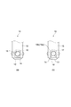
- FIG. 4A is a plan view showing a part on one end side of the bus bar in the terminal connection structure
- FIG. 4B is a front view showing a part on the other end side of the bus bar in the terminal connection structure.
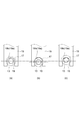
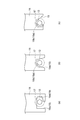
- FIG. 5A is a front view showing a state where the bolt is in a design position slightly spaced from the bottom of the notch
- FIG. 5B is a position where the bolt is on the open side of the notch from the design position.
- FIG. 5A is a front view showing a state where the bolt is in a design position slightly spaced from the bottom of the notch
- FIG. 5B is a position where the bolt is on the open side of the notch from the design position.
- FIG. 5C is a front view showing a state in which the bolt is on the bottom side of the notch portion with respect to the design position.
- FIG. 6 is a conceptual diagram showing the design position of the bolt with respect to the notch of the bus bar.
- FIG. 7 is a cross-sectional view showing an example of a conventional terminal connection structure.
- FIG. 8 is a cross-sectional view showing a part of a terminal connection structure according to another embodiment.
- FIG. 9 is a plan view showing a portion excluding the nut in the terminal connection structure shown in FIG.
- FIG. 10 is a diagram for explaining a modification of the terminal connection structure.
- FIG. 11 is a diagram for explaining a modification of the terminal connection structure.
- FIG. 12 is a diagram for explaining a modification of the terminal connection structure.
- FIG. 13 is a diagram for explaining a modification of the terminal connection structure.
- FIG. 14 is a diagram for explaining a modification of the terminal connection structure.
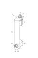
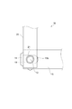
- FIG. 1 is a schematic side view showing a battery pack provided with a terminal connection structure according to an embodiment.
- the battery pack 1 includes a rectangular parallelepiped housing 2 and a battery module 3 accommodated in the housing 2.
- Connector terminals 4 ⁇ / b> A and 4 ⁇ / b> B are attached to the upper surface of the housing 2.
- the connector terminal 4A is a positive connector terminal
- the connector terminal 4B is a negative connector terminal.
- the battery module 3 has a plurality of batteries 5 such as a plurality of lithium ion secondary batteries arranged in one direction, although not specifically described in detail.
- Each battery 5 is provided with electrode terminals 6A and 6B.
- the electrode terminal 6A is a positive electrode terminal
- the electrode terminal 6B is a positive electrode terminal.
- the battery pack 1 includes terminal connection units 7A and 7B for connecting the connector terminals 4A and 4B and the electrode terminals 6A and 6B, respectively.
- the terminal connection units 7A and 7B have a terminal connection structure according to an embodiment of the present invention.
- a case where the terminal connection structure according to one embodiment of the present invention is applied to the terminal connection unit 7A will be described as an example.
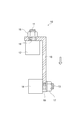
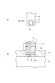
- FIG. 2 is a perspective view showing a terminal connection structure according to an embodiment.
- FIG. 3 is a cross-sectional view of the terminal connection structure shown in FIG. 2 and 3, the terminal connection structure 10 of the present embodiment includes a terminal block 12 (first terminal block) to which a bolt 11 (first bolt) is fixed and a bolt 13 (second bolt) fixed.
- a terminal block 14 (second terminal block), an L-shaped bus bar 15 that connects the bolt 11 and the bolt 13, and a nut 16 that is screwed to the bolt 11 and tightens one end of the bus bar 15 to the terminal block 12 ( A first nut) and a nut 17 (second nut) that is screwed to the bolt 13 and fastens the other end of the bus bar 15 to the terminal block 14.
- the bolts 11 and 13 and the nuts 16 and 17 are made of iron.
- the bus bar 15 is formed of a conductive member such as aluminum, copper, or iron. Thereby, the bolts 11 and 13 are electrically connected via the nut 16, the bus bar 15, and the nut 17.
- the axial direction of the bolt 11 and the axial direction of the bolt 13 are different. Specifically, the axial direction of the bolt 13 is perpendicular to the axial direction of the bolt 11. Accordingly, the bus bar 15 has a bent shape that is bent vertically.
- the bolt 11 is fixed in a state of being embedded in the terminal block 12 so that a part thereof protrudes from the upper surface of the terminal block 12.
- the bolt 13 is fixed in a state of being embedded in the terminal block 14 so that a part thereof protrudes from the upper surface of the terminal block 14.
- the nut 16 fastens one end side of the bus bar 15 to the terminal block 12 while being in contact with the bus bar 15.
- the nut 17 fastens the other end side of the bus bar 15 to the terminal block 14 while being in contact with the bus bar 15.
- the bolt 11 is connected to the connector terminal 4A through at least one other bus bar (not shown).
- the bolt 13 is connected to the electrode terminal 6A via at least one other bus bar (not shown).
- Other bus bars are in contact with the upper surfaces of the terminal blocks 12 and 14.
- a hole 18 having a circular cross section through which the bolt 11 is inserted is provided on one end side of the bus bar 15.
- the outer diameter of the seat surface of the nut 16 is larger than the inner diameter of the hole 18.
- the bottom surface 19a of the notch 19 has a semicircular cross section.
- the outer diameter of the seating surface of the nut 17 is equal to the outer diameter of the seating surface of the nut 16.
- the contact area between the nut 17 and the bus bar 15 is as follows.
- the contact area with 15 is smaller.
- the contact area between the nut 17 and the bus bar 15 varies depending on the positional relationship between the bolt 13 and the notch 19.
- the necessary contact area between the nut 17 and the bus bar 15 is ensured in a state where the bolt 13 is at a design position spaced from the bottom 19 b of the notch 19 by a predetermined amount. Is done.
- FIG. 5B in the state where the bolt 13 is on the open side of the notch 19 with respect to the design position, the contact area between the nut 17 and the bus bar 15 is reduced. A necessary contact area with the bus bar 15 is not ensured. In this case, the contact surface pressure between the nut 17 and the bus bar 15 is increased, and the nut 17 or the bus bar 15 is deformed in a depressed manner, so that the tightening of the bus bar 15 by the nut 17 is loosened.
- the design position of the bolt 13 with respect to the notch portion 19 of the bus bar 15 is the minimum value at which the contact area between the nut 17 and the bus bar 15 does not cause loosening of the tightening of the bus bar 15 by the nut 17.
- the first position where the bolt 13 is separated from the bottom 19b of the notch 19 P position in the figure
- the second position where the bolt 13 contacts the bottom 19b of the notch 19 Q position in the figure. It is set to an intermediate position.
- the contact area between the nut 17 and the bus bar 15 that is the minimum value that does not cause loosening of the bus bar 15 by the nut 17 is appropriately set according to the thickness and material of the bus bar 15, the dimensions of the notch portion 19, and the like.
- the intermediate position between the first position and the second position is offset to the open side of the notch 19 from the center G of the virtual circle X virtually formed by the bottom surface 19a of the notch 19 when viewed from the axial direction of the bolt 13. is doing.
- the center E of the bolt 13 when the bolt 13 is at the design position is located closer to the open side of the notch 19 than the center G of the virtual circle X. It is offset by a fixed amount e.
- the diameter of the virtual circle X is equal to the inner diameter of the hole 18.
- the bottom surface 19a of the notch 19 forms a half of the virtual circle X.
- the bolt 13 has a first position separated from the bottom portion 19b of the notch 19 so that the contact area between the nut 17 and the bus bar 15 becomes a minimum value that does not cause loosening of the tightening of the bus bar 15 by the nut 17, and the notch 19 and the second position where it contacts the bottom 19b.
- the bus bar 15 When the bus bar 15 is assembled to the terminal blocks 12, 14, the bus bar 15 is moved in the axial direction of the bolt 11 (the arrow direction in FIG. 3), so that the bolt 11 is inserted into the hole 18 of the bus bar 15 and the bus bar 15 The bolt 13 is inserted through the notch 19. Then, a nut 16 is screwed into the bolt 11 and one end of the bus bar 15 is fastened to the terminal block 12, and a nut 17 is screwed into the bolt 13 to tighten the other end of the bus bar 15 to the terminal block 14.
- FIG. 7 is a cross-sectional view showing an example of a conventional terminal connection structure.
- the terminal connection structure 50 includes an L-shaped bus bar 51 that connects the bolt 11 and the bolt 13. On both end sides of the bus bar 51, holes 52 and 53 having circular cross sections through which the bolts 11 and 13 are inserted are provided. Other configurations are the same as those of the terminal connection structure 10 described above.
- a hole 18 through which the bolt 11 is inserted is provided on one end side of the bus bar 15, and a notch 19 through which the bolt 13 is inserted is provided on the other end side of the bus bar 15.
- the notch 19 is open to the other end of the bus bar 15.
- the bolt 13 is the first spaced apart from the bottom portion 19b of the notch portion 19 so that the contact area between the nut 17 and the bus bar 15 becomes a minimum value that does not cause loosening of the tightening of the bus bar 15 by the nut 17. It is arranged between the position and the second position that abuts against the bottom 19 b of the notch 19. For this reason, the range which accept
- the first position is a position separated from the bottom portion 19b of the notch portion 19 so that the contact area between the nut 17 and the bus bar 15 becomes a minimum value that does not cause loosening of the tightening of the bus bar 15 by the nut 17.
- the second position is a position where the bolt 13 contacts the bottom 19 b of the notch 19. This prevents the bus bar 15 from being assembled to the terminal blocks 12 and 14.
- the intermediate position between the first position and the second position is notch from the center G of the virtual circle X that is virtually formed by the bottom surface 19a of the notch 19 when viewed from the axial direction of the bolt 13. It is offset to the open side of the part 19. Therefore, since the distance from the intermediate position between the first position and the second position to the first position and the second position becomes longer, the range in which the component tolerance is allowed in the notch portion 19 of the bus bar 15 can be further increased.
- FIG. 8 is a cross-sectional view showing a part of a terminal connection structure according to another embodiment of the present invention.
- FIG. 9 is a plan view showing a portion excluding the nut in the terminal connection structure shown in FIG. 8 and 9, one end side of the bus bar 20 is connected to the bolt 13.
- the bus bar 20 is connected to the bolt 13 while being superimposed on the bus bar 15. Therefore, the other end side of the bus bar 15 is in contact with the upper surface of the terminal block 14.
- the bus bar 20 extends in a direction perpendicular to the longitudinal direction of the bus bar 15.
- the nut 17 tightens the other end side of the bus bar 15 together with the bus bar 20 in contact with the bus bar 20.
- the nut 17 contacts the bus bar 20 having the hole portion 21 and does not contact the bus bar 15 having the notch portion 19. Therefore, even if the bolt 13 is disposed away from the bottom 19 b of the notch 19, the contact area between the nut 17 and the bus bar 20 is ensured, so that the other end of the bus bar 15 is connected to the terminal via the bus bar 20 by the nut 17. It is securely tightened against the base 14. Thus, even if the bolt 13 is arranged away from the bottom portion 19b of the notch portion 19, there is no particular problem, so that the range in which the component tolerance is allowed in the notch portion 19 of the bus bar 15 can be sufficiently widened.
- the bolt 13 and the notch 19 are deformed. More specifically, the bolt 13 here has a screwing portion 13a having a diameter C equivalent to the diameter of the bolt 13 shown in FIG. 4, and a diameter D smaller than the diameter C of the screwing portion 13a. A reduced diameter portion 13b. The reduced diameter portion 13b is located closer to the terminal block 14 than the screwing portion 13a. That is, here, the terminal 13 side portion of the bolt 13 is relatively thin. The nut 17 is screwed into the screwing portion 13a.
- the dimension A (diameter of the semicircle of the bottom surface 19a) of the cutout portion 19 is larger than the diameter D of the reduced diameter portion 13b and smaller than the diameter C of the screwing portion 13a. . That is, here, the notch 19 is made smaller than that in the above embodiment. In the notch portion 19, a relatively thin reduced diameter portion 13 b of the bolt 13 is disposed. According to this example, the contact area between the bus bar 15 and the nut 17 can be increased, and the assembly intersection can be reduced.
- the notch 19 can be variously modified as shown in FIG.
- the cutout portion 19 includes a portion 19c extending along the longitudinal direction of the bus bar 15, and a portion 19d extending continuously from the portion 19c in the short direction of the bus bar 15. Therefore, it is formed in an L shape.
- the extending direction of the portion 19d is, for example, along the surface direction (the direction along the plate surface) of the portion of the bus bar 15 where the hole 18 is formed. For this reason, for example, when the bus bar 15 rotates along the direction when the nut 16 is screwed into the bolt 11 inserted through the hole 18, the bolt 13 is prevented from contacting the inner surface of the notch 19.
- the notch 19 is formed in a tapered shape. More specifically, here, the cutout portion 19 includes a bottom portion 19b including a bottom surface 19a having a semicircular cross section, and a tapered portion 19e that expands from the bottom portion 19b toward the end of the bus bar 15. In this case, it becomes easy to arrange the bolt 13 in the notch 19.
- the entire extending direction of the notch 19 is inclined with respect to the longitudinal direction of the bus bar 15.
- the extending direction of the notch 19 can be arbitrarily set so that the bolt 13 can be easily disposed in the notch 19.
- the center E of the bolt 13 is positioned with respect to the short direction of the bus bar 15 (the direction in which the notch 19 is passed) in anticipation of a deviation during assembly. It may be offset from the center of the notch 19 by a fixed amount e. In this case, the shift E causes the center E of the bolt 13 to be close to the center of the notch 19, and the reduction of the contact area between the nut 17 and the bus bar 15 can be suppressed. In particular, when the diameter of the seat surface of the nut 17 and the width of the bus bar 15 (dimension in the short direction) are approximately the same, the reduction in the contact area due to the shift in the direction becomes significant. The modified example becomes more effective.
- the axial direction of the bolt 11 and the axial direction of the bolt 13 are orthogonal to each other.
- the shape is not particularly limited, and the axial direction of the bolt 11 and the axial direction of the bolt 13 intersect. If you do.
- the bending angle of the bus bar 15 corresponds to the intersection angle between the axial direction of the bolt 11 and the axial direction of the bolt 13.
- the crossing angle between the axial direction of the bolt 11 and the axial direction of the bolt 13 is smaller than 90 °.
- the bending angle of the bus bar 15 is larger than 90 ° by the difference between the intersection angle and 90 °.
- the intersection angle between the axial direction of the bolt 11 and the axial direction of the bolt 13 and the bending angle of the bus bar 15 may be set independently of each other, and various modifications are possible.
- a plurality of (two here) notches 19 may be provided for a single bus bar 15 (the same applies to the holes 18).
- the notch portion 19 is formed with respect to the hole portion 18 along the surface direction (direction along the plate surface) of the portion where the hole portion 18 is provided in the bus bar 15. May be shifted.
- the bus bar 15 includes a portion 15a in which the hole 18 is provided, a portion 15b extending from the portion 15a in a direction intersecting (orthogonal to) the portion 15a, as in the above embodiment, including.
- the bus bar 15 is formed in an L-shaped plate shape by a portion 15a and a portion 15b. Further, the bus bar 15 includes a portion 15c protruding from the portion 15b along the surface direction of the portion 15a. And the notch part 19 is provided in this part 15c. Thereby, here, the formation position of the notch 19 is shifted with respect to the formation position of the hole 18 along the surface direction of the portion 15a.
- the positional relationship between the hole 18 and the notch 19 can be arbitrarily set according to the manner of assembly.
- the terminal connection structure 10 of the above embodiment is applied to the terminal connection units 7A and 7B that connect the connector terminals 4A and 4B and the electrode terminals 6A and 6B, respectively.
- the present invention is not limited to such a terminal connection unit, and any structure that connects terminals in a battery pack can be applied.
- a battery pack terminal connection structure is provided that can improve the ease of assembling the bus bar when bolts having different axial directions are connected by a bent bus bar.
Abstract
This terminal connection structure comprises: a first terminal block whereon a first bolt is fixed; a second terminal block whereon a second bolt is fixed, the second bolt having a different axis direction to that of the first bolt; a bent bus bar connecting the first bolt to the second bolt; a first nut screwed onto the first bolt and fastening one end side of the bus bar against the first terminal block; and a second nut screwed onto the second bolt and fastening the other end side of the bus bar against the second terminal block. Provided on the one end side of the bus bar is a hole portion through which the first bolt is inserted. Provided on the other end side of the bus bar is a cut-out portion which opens toward the other end of the bus bar, and through which the second bolt is inserted.
Description
本発明の一側面は、電池パックの端子接続構造に関する。
One aspect of the present invention relates to a terminal connection structure of a battery pack.
従来における電池パックの端子接続構造としては、例えば特許文献1に記載されている技術が知られている。特許文献1に記載の電池パックの端子接続構造は、電池セルの電極端子と出力ラインとを接続する中継バスバーを備えている。中継バスバーは、屈曲加工されている。中継バスバーの一端側には、電極端子の止ネジが貫通する貫通孔が設けられ、中継バスバーの他端側には、エンドプレートに固定されたナットにねじ込まれる止ネジが貫通する貫通孔が設けられている。
As a conventional battery pack terminal connection structure, for example, a technique described in Patent Document 1 is known. The terminal connection structure of the battery pack described in Patent Literature 1 includes a relay bus bar that connects the electrode terminal of the battery cell and the output line. The relay bus bar is bent. A through hole through which the set screw of the electrode terminal passes is provided on one end side of the relay bus bar, and a through hole through which a set screw screwed into a nut fixed to the end plate is provided on the other end side of the relay bus bar. It has been.
ところで、電池パックの端子接続構造においては、第1端子台に固定された第1ボルトと第2端子台に固定された第2ボルトとをバスバーにより接続することがある。このとき、第1ボルトの軸方向と第2ボルトの軸方向とが異なる場合には、上記従来技術のように、第1ボルト及び第2ボルトが貫通する貫通孔が両端側にそれぞれ設けられた屈曲形状のバスバーが使用される。しかし、このような構造では、バスバーを第1端子台及び第2端子台に一方向から組み付けることは不可能である。このため、バスバーの一方の貫通孔に第1ボルトを通した後、バスバーを回転させながらバスバーの他方の貫通孔に第2ボルトを通す必要がある。従って、バスバーの組み付けが困難である。また、部品公差によってはバスバーの組み付けができない場合がある。
By the way, in the terminal connection structure of the battery pack, the first bolt fixed to the first terminal block and the second bolt fixed to the second terminal block may be connected by the bus bar. At this time, when the axial direction of the first bolt is different from the axial direction of the second bolt, the through holes through which the first bolt and the second bolt pass are respectively provided at both ends as in the prior art. A bent bus bar is used. However, with such a structure, it is impossible to assemble the bus bar to the first terminal block and the second terminal block from one direction. For this reason, after passing the first bolt through one through hole of the bus bar, it is necessary to pass the second bolt through the other through hole of the bus bar while rotating the bus bar. Therefore, it is difficult to assemble the bus bar. Also, depending on component tolerances, the bus bar may not be assembled.
本発明の一側面は、軸方向が異なるボルト同士を屈曲形状のバスバーにより接続する場合に、バスバーの組み付け性を向上させることができる電池パックの端子接続構造を提供することを目的とする。
An object of one aspect of the present invention is to provide a battery pack terminal connection structure that can improve assemblability of a bus bar when bolts having different axial directions are connected by a bent bus bar.
本発明の一側面に係る電池パックの端子接続構造は、第1ボルトが固定された第1端子台と、第1ボルトとは軸方向が異なる第2ボルトが固定された第2端子台と、第1ボルトと第2ボルトとを接続する屈曲形状のバスバーと、第1ボルトと螺合し、バスバーの一端側を第1端子台に対して締め付ける第1ナットと、第2ボルトと螺合し、バスバーの他端側を第2端子台に対して締め付ける第2ナットとを備え、バスバーの一端側には、第1ボルトが挿通する孔部が設けられており、バスバーの他端側には、バスバーの他端に開放し、第2ボルトが挿通する切欠部が設けられていることを特徴とする。
A battery pack terminal connection structure according to one aspect of the present invention includes a first terminal block to which a first bolt is fixed, a second terminal block to which a second bolt having a different axial direction from the first bolt is fixed, A bent bus bar that connects the first bolt and the second bolt, a first nut that is screwed to the first bolt, and that fastens one end of the bus bar to the first terminal block, and a second bolt that is screwed. And a second nut for fastening the other end of the bus bar to the second terminal block. A hole through which the first bolt is inserted is provided at one end of the bus bar, and the other end of the bus bar is provided at the other end. The other end of the bus bar is provided with a notch through which the second bolt is inserted.
このような電池パックの端子接続構造において、屈曲形状のバスバーを第1端子台及び第2端子台に組み付けるときは、バスバーの一端側に設けられた孔部に第1ボルトを挿通させると共に、バスバーの他端側に設けられた切欠部に第2ボルトを挿通させた状態で、第1ボルトに第1ナットをねじ込んでバスバーの一端側を第1端子台に対して締め付けると共に、第2ボルトに第2ナットをねじ込んでバスバーの他端側を第2端子台に対して締め付ける。このとき、切欠部はバスバーの他端に開放しているため、第1ボルトが孔部を挿通するようにバスバーを第1ボルトの軸方向に移動させると、第2ボルトが切欠部を挿通するようになる。従って、バスバーを第1端子台及び第2端子台に一方向から組み付けることが可能となる。これにより、軸方向が異なる第1ボルト及び第2ボルト同士を屈曲形状のバスバーにより接続する場合に、バスバーの組み付け性を向上させることができる。
In such a battery pack terminal connection structure, when the bent bus bar is assembled to the first terminal block and the second terminal block, the first bolt is inserted into the hole provided at one end of the bus bar, and the bus bar With the second bolt inserted through the notch provided on the other end of the first screw, the first nut is screwed into the first bolt to tighten one end of the bus bar against the first terminal block, and the second bolt The second nut is screwed and the other end of the bus bar is tightened against the second terminal block. At this time, since the notch is open to the other end of the bus bar, when the bus bar is moved in the axial direction of the first bolt so that the first bolt passes through the hole, the second bolt passes through the notch. It becomes like this. Therefore, the bus bar can be assembled to the first terminal block and the second terminal block from one direction. Thereby, when connecting the 1st volt | bolt and 2nd volt | bolt from which an axial direction differs by a bent-shaped bus bar, the assembly | attachment property of a bus bar can be improved.
第2ナットは、バスバーに接触した状態でバスバーの他端側を第2端子台に対して締め付け、第2ボルトは、第2ナットとバスバーとの接触面積が第2ナットによるバスバーの締め付けの緩みを生じさせない最小値となるように切欠部の底部から離間した第1位置と、切欠部の底部に当接する第2位置との間に配置されていてもよい。
The second nut is in contact with the bus bar and the other end of the bus bar is tightened against the second terminal block. The second bolt has a contact area between the second nut and the bus bar that is loosened by the second nut. It may be arranged between a first position spaced from the bottom of the notch and a second position in contact with the bottom of the notch so as to have a minimum value that does not cause the.
このように第2ボルトは上記第1位置と上記第2位置との間に配置されるので、バスバーの切欠部において部品公差を許容する範囲を広くとることができる。このとき、第1位置は、第2ナットとバスバーとの接触面積が第2ナットによるバスバーの締め付けの緩みを生じさせない最小値となるように切欠部の底部から離間した位置である。このため、第2ナットとバスバーとの接触面積は、常に当該最小値以上となる。従って、第2ナットとバスバーとの接触面圧の増加に起因する第2ナットまたはバスバーの変形によって第2ナットによるバスバーの他端側の締め付けが緩むことが防止される。また、第2位置は、第2ボルトが切欠部の底部に当接する位置である。このため、バスバーが第1端子台及び第2端子台に組み付けられなくなることが防止される。
Thus, since the second bolt is disposed between the first position and the second position, it is possible to widen a range in which a part tolerance is allowed in the notch portion of the bus bar. At this time, the first position is a position spaced from the bottom of the notch so that the contact area between the second nut and the bus bar is a minimum value that does not cause loosening of the tightening of the bus bar by the second nut. For this reason, the contact area between the second nut and the bus bar is always equal to or greater than the minimum value. Accordingly, it is possible to prevent the tightening of the other end of the bus bar by the second nut from being loosened due to the deformation of the second nut or the bus bar due to the increase in the contact surface pressure between the second nut and the bus bar. The second position is a position where the second bolt comes into contact with the bottom of the notch. For this reason, it becomes possible to prevent the bus bar from being assembled to the first terminal block and the second terminal block.
切欠部の底面は、断面半円形状を呈し、第1位置と第2位置との中間位置は、第2ボルトの軸方向から見て切欠部の底面によって仮想的に形成される仮想円の中心よりも切欠部の開放側にオフセットしていてもよい。
The bottom surface of the notch has a semicircular cross section, and the intermediate position between the first position and the second position is the center of a virtual circle virtually formed by the bottom surface of the notch when viewed from the axial direction of the second bolt. It may be offset to the open side of the notch.
このような構成では、第1位置と第2位置との中間位置から第1位置及び第2位置までの距離が長くなるため、バスバーの切欠部において部品公差を許容する範囲を更に広くとることができる。
In such a configuration, since the distance from the intermediate position between the first position and the second position to the first position and the second position becomes longer, the range allowing the part tolerance at the notch portion of the bus bar can be further widened. it can.
バスバーの上に重ねられた状態で第2ボルトに接続される他のバスバーを更に備え、他のバスバーには、第2ボルトが挿通する孔部が設けられており、第2ナットは、他のバスバーに接触した状態でバスバーの他端側を他のバスバーと共に第2端子台に対して締め付けてもよい。
The bus bar is further provided with another bus bar connected to the second bolt in a state of being superimposed on the bus bar, and the other bus bar is provided with a hole through which the second bolt is inserted. You may clamp | tighten the other end side of a bus bar with respect to a 2nd terminal block with another bus bar in the state which contacted the bus bar.
このような構成では、第2ナットは、孔部を有する他のバスバーに接触し、切欠部を有するバスバーには接触しない。従って、第2ボルトが切欠部の底部から離間して配置されても、第2ナットと他のバスバーとの接触面積が確保されるため、第2ナットによりバスバーの他端側が他のバスバーを介して第2端子台に対して確実に締め付けられる。このように第2ボルトが切欠部の底部から離間して配置されても、特に支障はないため、バスバーの切欠部において部品公差を許容する範囲を十分に広くとることができる。
In such a configuration, the second nut contacts another bus bar having a hole, and does not contact a bus bar having a notch. Therefore, even if the second bolt is arranged away from the bottom of the notch, a contact area between the second nut and the other bus bar is ensured, so that the other end side of the bus bar is inserted through the other bus bar by the second nut. And securely tightened against the second terminal block. Thus, even if the second bolt is arranged away from the bottom of the notch, there is no particular problem, so that the range for allowing the component tolerance in the notch of the bus bar can be sufficiently widened.
本発明の一側面によれば、軸方向が異なるボルト同士を屈曲形状のバスバーにより接続する場合に、バスバーの組み付け性を向上させることができる電池パックの端子接続構造が提供される。
According to an aspect of the present invention, there is provided a battery pack terminal connection structure capable of improving the assemblability of a bus bar when bolts having different axial directions are connected by a bent bus bar.
以下、本発明の一側面に係る実施形態について、図面を参照して詳細に説明する。なお、図面において、同一または同等の要素には同じ符号を付し、重複する説明を省略する。
Hereinafter, embodiments according to one aspect of the present invention will be described in detail with reference to the drawings. In the drawings, the same or equivalent elements are denoted by the same reference numerals, and redundant description is omitted.
図1は、一実施形態に係る端子接続構造を備えた電池パックを示す概略側面図である。図1において、電池パック1は、直方体形状の筐体2と、この筐体2内に収容された電池モジュール3とを備えている。筐体2の上面には、コネクタ端子4A,4Bが取り付けられている。コネクタ端子4Aは正極用コネクタ端子であり、コネクタ端子4Bは負極用コネクタ端子である。
FIG. 1 is a schematic side view showing a battery pack provided with a terminal connection structure according to an embodiment. In FIG. 1, the battery pack 1 includes a rectangular parallelepiped housing 2 and a battery module 3 accommodated in the housing 2. Connector terminals 4 </ b> A and 4 </ b> B are attached to the upper surface of the housing 2. The connector terminal 4A is a positive connector terminal, and the connector terminal 4B is a negative connector terminal.
電池モジュール3は、特に詳述はしないが、一方向に配列された複数のリチウムイオン二次電池等の電池5を有している。各電池5には、電極端子6A,6Bが設けられている。電極端子6Aは正極端子であり、電極端子6Bは正極端子である。
The battery module 3 has a plurality of batteries 5 such as a plurality of lithium ion secondary batteries arranged in one direction, although not specifically described in detail. Each battery 5 is provided with electrode terminals 6A and 6B. The electrode terminal 6A is a positive electrode terminal, and the electrode terminal 6B is a positive electrode terminal.
また、電池パック1は、コネクタ端子4A,4Bと電極端子6A,6Bとをそれぞれ接続する端子接続ユニット7A,7Bを備えている。端子接続ユニット7A,7Bは、本発明の一実施形態に係る端子接続構造を有している。以下、本発明の一実施形態に係る端子接続構造を端子接続ユニット7Aに適用した場合を例にとって説明する。
Further, the battery pack 1 includes terminal connection units 7A and 7B for connecting the connector terminals 4A and 4B and the electrode terminals 6A and 6B, respectively. The terminal connection units 7A and 7B have a terminal connection structure according to an embodiment of the present invention. Hereinafter, a case where the terminal connection structure according to one embodiment of the present invention is applied to the terminal connection unit 7A will be described as an example.
図2は、一実施形態に係る端子接続構造を示す斜視図である。図3は、図2に示された端子接続構造の断面図である。図2及び図3において、本実施形態の端子接続構造10は、ボルト11(第1ボルト)が固定された端子台12(第1端子台)と、ボルト13(第2ボルト)が固定された端子台14(第2端子台)と、ボルト11とボルト13とを接続するL字形のバスバー15と、ボルト11と螺合し、バスバー15の一端側を端子台12に対して締め付けるナット16(第1ナット)と、ボルト13と螺合し、バスバー15の他端側を端子台14に対して締め付けるナット17(第2ナット)とを備えている。
FIG. 2 is a perspective view showing a terminal connection structure according to an embodiment. FIG. 3 is a cross-sectional view of the terminal connection structure shown in FIG. 2 and 3, the terminal connection structure 10 of the present embodiment includes a terminal block 12 (first terminal block) to which a bolt 11 (first bolt) is fixed and a bolt 13 (second bolt) fixed. A terminal block 14 (second terminal block), an L-shaped bus bar 15 that connects the bolt 11 and the bolt 13, and a nut 16 that is screwed to the bolt 11 and tightens one end of the bus bar 15 to the terminal block 12 ( A first nut) and a nut 17 (second nut) that is screwed to the bolt 13 and fastens the other end of the bus bar 15 to the terminal block 14.
ボルト11,13及びナット16,17は、鉄で形成されている。バスバー15は、アルミニウム、銅または鉄等の導電部材で形成されている。これにより、ボルト11,13同士は、ナット16、バスバー15及びナット17を介して電気的に接続されている。
The bolts 11 and 13 and the nuts 16 and 17 are made of iron. The bus bar 15 is formed of a conductive member such as aluminum, copper, or iron. Thereby, the bolts 11 and 13 are electrically connected via the nut 16, the bus bar 15, and the nut 17.
ボルト11の軸方向とボルト13の軸方向とは異なっている。具体的には、ボルト13の軸方向は、ボルト11の軸方向に対して垂直となっている。従って、バスバー15は、垂直に屈曲した屈曲形状を呈している。ボルト11は、一部が端子台12の上面から突出するように端子台12の内部に埋め込まれた状態で固定されている。ボルト13は、一部が端子台14の上面から突出するように端子台14の内部に埋め込まれた状態で固定されている。ナット16は、バスバー15に接触した状態でバスバー15の一端側を端子台12に対して締め付ける。ナット17は、バスバー15に接触した状態でバスバー15の他端側を端子台14に対して締め付ける。
The axial direction of the bolt 11 and the axial direction of the bolt 13 are different. Specifically, the axial direction of the bolt 13 is perpendicular to the axial direction of the bolt 11. Accordingly, the bus bar 15 has a bent shape that is bent vertically. The bolt 11 is fixed in a state of being embedded in the terminal block 12 so that a part thereof protrudes from the upper surface of the terminal block 12. The bolt 13 is fixed in a state of being embedded in the terminal block 14 so that a part thereof protrudes from the upper surface of the terminal block 14. The nut 16 fastens one end side of the bus bar 15 to the terminal block 12 while being in contact with the bus bar 15. The nut 17 fastens the other end side of the bus bar 15 to the terminal block 14 while being in contact with the bus bar 15.
なお、ボルト11は、少なくとも1つの他のバスバー(図示せず)を介してコネクタ端子4Aと接続されている。ボルト13は、少なくとも1つの他のバスバー(図示せず)を介して電極端子6Aと接続されている。他のバスバーは、端子台12,14の上面に接触している。
The bolt 11 is connected to the connector terminal 4A through at least one other bus bar (not shown). The bolt 13 is connected to the electrode terminal 6A via at least one other bus bar (not shown). Other bus bars are in contact with the upper surfaces of the terminal blocks 12 and 14.
バスバー15の一端側には、図3及び図4(a)に示されるように、ボルト11が挿通する断面円形状の孔部18が設けられている。ナット16の座面の外径は、孔部18の内径よりも大きい。バスバー15の他端側には、図3及び図4(b)に示されるように、バスバー15の他端に開放し、ボルト13が挿通する切欠部19が設けられている。切欠部19の底面19aは、断面半円形状を呈している。ナット17の座面の外径は、ナット16の座面の外径と等しい。
As shown in FIG. 3 and FIG. 4A, a hole 18 having a circular cross section through which the bolt 11 is inserted is provided on one end side of the bus bar 15. The outer diameter of the seat surface of the nut 16 is larger than the inner diameter of the hole 18. On the other end side of the bus bar 15, as shown in FIG. 3 and FIG. 4B, there is provided a notch 19 that opens to the other end of the bus bar 15 and through which the bolt 13 is inserted. The bottom surface 19a of the notch 19 has a semicircular cross section. The outer diameter of the seating surface of the nut 17 is equal to the outer diameter of the seating surface of the nut 16.
このようにバスバー15の一端側には孔部18が設けられ、バスバー15の他端側には切欠部19が設けられているため、ナット17とバスバー15との接触面積は、ナット16とバスバー15との接触面積よりも小さくなる。ところで、ボルト13とバスバー15の切欠部19との間には、図5に示されるように、部品公差が発生する。このとき、ボルト13と切欠部19との位置関係によってナット17とバスバー15との接触面積が変わってくる。
Thus, since the hole 18 is provided on one end side of the bus bar 15 and the notch 19 is provided on the other end side of the bus bar 15, the contact area between the nut 17 and the bus bar 15 is as follows. The contact area with 15 is smaller. By the way, as shown in FIG. 5, there is a component tolerance between the bolt 13 and the notch 19 of the bus bar 15. At this time, the contact area between the nut 17 and the bus bar 15 varies depending on the positional relationship between the bolt 13 and the notch 19.
具体的には、図5(a)に示されるように、ボルト13が切欠部19の底部19bから所定量だけ離間した設計位置にある状態では、ナット17とバスバー15との必要接触面積が確保される。しかし、図5(b)に示されるように、ボルト13が設計位置よりも切欠部19の開放側にある状態では、ナット17とバスバー15との接触面積が減少し、場合によってはナット17とバスバー15との必要接触面積が確保されなくなる。この場合には、ナット17とバスバー15との接触面圧が高くなり、ナット17またはバスバー15が陥没変形することで、ナット17によるバスバー15の締め付けの緩みが生じる。また、図5(c)に示されるように、ボルト13が設計位置よりも切欠部19の底部19b側にある状態では、ナット17とバスバー15との接触面積が増加するが、切欠部19の深さによってはバスバー15が端子台14に組み付けられなくなる。
Specifically, as shown in FIG. 5A, the necessary contact area between the nut 17 and the bus bar 15 is ensured in a state where the bolt 13 is at a design position spaced from the bottom 19 b of the notch 19 by a predetermined amount. Is done. However, as shown in FIG. 5B, in the state where the bolt 13 is on the open side of the notch 19 with respect to the design position, the contact area between the nut 17 and the bus bar 15 is reduced. A necessary contact area with the bus bar 15 is not ensured. In this case, the contact surface pressure between the nut 17 and the bus bar 15 is increased, and the nut 17 or the bus bar 15 is deformed in a depressed manner, so that the tightening of the bus bar 15 by the nut 17 is loosened. Further, as shown in FIG. 5C, in the state where the bolt 13 is on the bottom 19b side of the notch 19 from the design position, the contact area between the nut 17 and the bus bar 15 increases. The bus bar 15 cannot be assembled to the terminal block 14 depending on the depth.
そこで、バスバー15の切欠部19に対するボルト13の設計位置は、図6に示されるように、ナット17とバスバー15との接触面積がナット17によるバスバー15の締め付けの緩みを生じさせない最小値となるようにボルト13が切欠部19の底部19bから離間した第1位置(図中のP位置)と、ボルト13が切欠部19の底部19bに当接する第2位置(図中のQ位置)との中間位置に設定されている。
Therefore, as shown in FIG. 6, the design position of the bolt 13 with respect to the notch portion 19 of the bus bar 15 is the minimum value at which the contact area between the nut 17 and the bus bar 15 does not cause loosening of the tightening of the bus bar 15 by the nut 17. In this way, the first position where the bolt 13 is separated from the bottom 19b of the notch 19 (P position in the figure) and the second position where the bolt 13 contacts the bottom 19b of the notch 19 (Q position in the figure). It is set to an intermediate position.
ナット17によるバスバー15の締め付けの緩みを生じさせない最小値となるようなナット17とバスバー15との接触面積は、バスバー15の厚み及び材料、切欠部19の寸法等に応じて適宜設定される。
The contact area between the nut 17 and the bus bar 15 that is the minimum value that does not cause loosening of the bus bar 15 by the nut 17 is appropriately set according to the thickness and material of the bus bar 15, the dimensions of the notch portion 19, and the like.
第1位置と第2位置との中間位置は、ボルト13の軸方向から見て切欠部19の底面19aによって仮想的に形成される仮想円Xの中心Gよりも切欠部19の開放側にオフセットしている。具体的には、ボルト13が設計位置(第1位置と第2位置との中間位置)にあるときのボルト13の中心Eは、仮想円Xの中心Gよりも切欠部19の開放側に所定量eだけオフセットしている。仮想円Xの直径は、孔部18の内径と等しい。切欠部19の底面19aは、仮想円Xの半分の部分を形成している。
The intermediate position between the first position and the second position is offset to the open side of the notch 19 from the center G of the virtual circle X virtually formed by the bottom surface 19a of the notch 19 when viewed from the axial direction of the bolt 13. is doing. Specifically, the center E of the bolt 13 when the bolt 13 is at the design position (intermediate position between the first position and the second position) is located closer to the open side of the notch 19 than the center G of the virtual circle X. It is offset by a fixed amount e. The diameter of the virtual circle X is equal to the inner diameter of the hole 18. The bottom surface 19a of the notch 19 forms a half of the virtual circle X.
従って、ボルト13は、ナット17とバスバー15との接触面積がナット17によるバスバー15の締め付けの緩みを生じさせない最小値となるように切欠部19の底部19bから離間した第1位置と、切欠部19の底部19bに当接する第2位置との間に配置されることとなる。
Accordingly, the bolt 13 has a first position separated from the bottom portion 19b of the notch 19 so that the contact area between the nut 17 and the bus bar 15 becomes a minimum value that does not cause loosening of the tightening of the bus bar 15 by the nut 17, and the notch 19 and the second position where it contacts the bottom 19b.
バスバー15を端子台12,14に組み付けるときは、バスバー15をボルト11の軸方向(図3の矢印方向)に移動させることで、バスバー15の孔部18にボルト11を挿通させると共に、バスバー15の切欠部19にボルト13を挿通させる。そして、ボルト11にナット16をねじ込んでバスバー15の一端側を端子台12に対して締め付けると共に、ボルト13にナット17をねじ込んでバスバー15の他端側を端子台14に対して締め付ける。
When the bus bar 15 is assembled to the terminal blocks 12, 14, the bus bar 15 is moved in the axial direction of the bolt 11 (the arrow direction in FIG. 3), so that the bolt 11 is inserted into the hole 18 of the bus bar 15 and the bus bar 15 The bolt 13 is inserted through the notch 19. Then, a nut 16 is screwed into the bolt 11 and one end of the bus bar 15 is fastened to the terminal block 12, and a nut 17 is screwed into the bolt 13 to tighten the other end of the bus bar 15 to the terminal block 14.
図7は、従来の端子接続構造の一例を示す断面図である。図7において、端子接続構造50は、ボルト11とボルト13とを接続するL字形のバスバー51を備えている。バスバー51の両端側には、ボルト11,13が挿通する断面円形状の孔部52,53がそれぞれ設けられている。その他の構成は、上記の端子接続構造10と同様である。
FIG. 7 is a cross-sectional view showing an example of a conventional terminal connection structure. In FIG. 7, the terminal connection structure 50 includes an L-shaped bus bar 51 that connects the bolt 11 and the bolt 13. On both end sides of the bus bar 51, holes 52 and 53 having circular cross sections through which the bolts 11 and 13 are inserted are provided. Other configurations are the same as those of the terminal connection structure 10 described above.
このような端子接続構造50では、ボルト11の軸方向とボルト13の軸方向とが直交しているため、バスバー51を端子台12,14に一方向から組み付けることが不可能である。このため、バスバー51の孔部52にボルト11を通した後、バスバー51を回転させながらバスバー51の孔部53にボルト13を通す必要がある。しかし、この場合には、ボルト11,13の長さ及び孔部52,53の径等を適切に設計しないと、バスバー51を端子台12,14に組み付けることができない。
In such a terminal connection structure 50, since the axial direction of the bolt 11 and the axial direction of the bolt 13 are orthogonal, it is impossible to assemble the bus bar 51 to the terminal blocks 12 and 14 from one direction. For this reason, it is necessary to pass the bolt 13 through the hole 53 of the bus bar 51 while rotating the bus bar 51 after passing the bolt 11 through the hole 52 of the bus bar 51. However, in this case, the bus bar 51 cannot be assembled to the terminal blocks 12 and 14 unless the lengths of the bolts 11 and 13 and the diameters of the holes 52 and 53 are appropriately designed.
これに対し本実施形態では、バスバー15の一端側に、ボルト11が挿通する孔部18が設けられ、バスバー15の他端側に、ボルト13が挿通する切欠部19が設けられている。切欠部19は、バスバー15の他端に開放している。このため、ボルト11が孔部18を挿通するようにバスバー15をボルト11の軸方向に移動させると、ボルト13が切欠部19を挿通するようになる。従って、バスバー15を端子台12,14に一方向から組み付けることが可能となる。これにより、軸方向が異なるボルト11,13同士を屈曲形状のバスバー15により接続する場合に、バスバー15の組み付け性を向上させることができる。
In contrast, in this embodiment, a hole 18 through which the bolt 11 is inserted is provided on one end side of the bus bar 15, and a notch 19 through which the bolt 13 is inserted is provided on the other end side of the bus bar 15. The notch 19 is open to the other end of the bus bar 15. For this reason, when the bus bar 15 is moved in the axial direction of the bolt 11 so that the bolt 11 passes through the hole portion 18, the bolt 13 passes through the notch portion 19. Therefore, the bus bar 15 can be assembled to the terminal blocks 12 and 14 from one direction. Accordingly, when the bolts 11 and 13 having different axial directions are connected to each other by the bent bus bar 15, the assembling property of the bus bar 15 can be improved.
また、本実施形態では、ボルト13は、ナット17とバスバー15との接触面積がナット17によるバスバー15の締め付けの緩みを生じさせない最小値となるように切欠部19の底部19bから離間した第1位置と、切欠部19の底部19bに当接する第2位置との間に配置されている。このため、バスバー15の切欠部19において部品公差を許容する範囲を広くとることができる。このとき、第1位置は、ナット17とバスバー15との接触面積がナット17によるバスバー15の締め付けの緩みを生じさせない最小値となるように切欠部19の底部19bから離間した位置である。このため、ナット17とバスバー15との接触面積は、常に当該最小値以上となる。従って、ナット17とバスバー15との接触面圧の増加に起因するナット17またはバスバー15の変形によってナット17によるバスバー15の他端側の締め付けが緩むことが防止される。また、第2位置は、ボルト13が切欠部19の底部19bに当接する位置である。このため、バスバー15が端子台12,14に組み付けられなくなることが防止される。
Further, in the present embodiment, the bolt 13 is the first spaced apart from the bottom portion 19b of the notch portion 19 so that the contact area between the nut 17 and the bus bar 15 becomes a minimum value that does not cause loosening of the tightening of the bus bar 15 by the nut 17. It is arranged between the position and the second position that abuts against the bottom 19 b of the notch 19. For this reason, the range which accept | permits component tolerance in the notch part 19 of the bus-bar 15 can be taken widely. At this time, the first position is a position separated from the bottom portion 19b of the notch portion 19 so that the contact area between the nut 17 and the bus bar 15 becomes a minimum value that does not cause loosening of the tightening of the bus bar 15 by the nut 17. For this reason, the contact area between the nut 17 and the bus bar 15 is always greater than or equal to the minimum value. Therefore, the tightening of the other end side of the bus bar 15 by the nut 17 due to deformation of the nut 17 or the bus bar 15 due to an increase in the contact surface pressure between the nut 17 and the bus bar 15 is prevented. The second position is a position where the bolt 13 contacts the bottom 19 b of the notch 19. This prevents the bus bar 15 from being assembled to the terminal blocks 12 and 14.
また、本実施形態では、第1位置と第2位置との中間位置は、ボルト13の軸方向から見て切欠部19の底面19aによって仮想的に形成される仮想円Xの中心Gよりも切欠部19の開放側にオフセットしている。従って、第1位置と第2位置との中間位置から第1位置及び第2位置までの距離が長くなるため、バスバー15の切欠部19において部品公差を許容する範囲を更に広くとることができる。
Further, in the present embodiment, the intermediate position between the first position and the second position is notch from the center G of the virtual circle X that is virtually formed by the bottom surface 19a of the notch 19 when viewed from the axial direction of the bolt 13. It is offset to the open side of the part 19. Therefore, since the distance from the intermediate position between the first position and the second position to the first position and the second position becomes longer, the range in which the component tolerance is allowed in the notch portion 19 of the bus bar 15 can be further increased.
図8は、本発明の他の実施形態に係る端子接続構造の一部を示す断面図である。図9は、図8に示された端子接続構造におけるナットを除く部分を示す平面図である。図8及び図9において、ボルト13には、バスバー20の一端側が接続されている。バスバー20の一端側には、ボルト13が挿通する断面円形状の孔部21が設けられている。バスバー20は、バスバー15の上に重ねられた状態でボルト13に接続されている。従って、バスバー15の他端側は、端子台14の上面に接触していることとなる。バスバー20は、バスバー15の長手方向に対して垂直な方向に延びている。ナット17は、バスバー20に接触した状態でバスバー15の他端側をバスバー20と共に締め付ける。
FIG. 8 is a cross-sectional view showing a part of a terminal connection structure according to another embodiment of the present invention. FIG. 9 is a plan view showing a portion excluding the nut in the terminal connection structure shown in FIG. 8 and 9, one end side of the bus bar 20 is connected to the bolt 13. On one end side of the bus bar 20, a hole 21 having a circular cross section through which the bolt 13 is inserted is provided. The bus bar 20 is connected to the bolt 13 while being superimposed on the bus bar 15. Therefore, the other end side of the bus bar 15 is in contact with the upper surface of the terminal block 14. The bus bar 20 extends in a direction perpendicular to the longitudinal direction of the bus bar 15. The nut 17 tightens the other end side of the bus bar 15 together with the bus bar 20 in contact with the bus bar 20.
本実施形態においては、ナット17は、孔部21を有するバスバー20に接触し、切欠部19を有するバスバー15には接触しない。従って、ボルト13が切欠部19の底部19bから離間して配置されても、ナット17とバスバー20との接触面積が確保されるため、ナット17によりバスバー15の他端側がバスバー20を介して端子台14に対して確実に締め付けられる。このようにボルト13が切欠部19の底部19bから離間して配置されても、特に支障はないため、バスバー15の切欠部19において部品公差を許容する範囲を十分に広くとることができる。
In the present embodiment, the nut 17 contacts the bus bar 20 having the hole portion 21 and does not contact the bus bar 15 having the notch portion 19. Therefore, even if the bolt 13 is disposed away from the bottom 19 b of the notch 19, the contact area between the nut 17 and the bus bar 20 is ensured, so that the other end of the bus bar 15 is connected to the terminal via the bus bar 20 by the nut 17. It is securely tightened against the base 14. Thus, even if the bolt 13 is arranged away from the bottom portion 19b of the notch portion 19, there is no particular problem, so that the range in which the component tolerance is allowed in the notch portion 19 of the bus bar 15 can be sufficiently widened.
なお、本発明の一側面は、上記実施形態には限定されない。引き続いて、端子接続構造10の変形例について説明する。図10に示される例では、ボルト13及び切欠部19が変形されている。より具体的には、ここでのボルト13は、図4に示されたボルト13の直径と同等の直径Cを有する螺合部13aと、螺合部13aの直径Cよりも小さな直径Dを有する縮径部13bと、を含む。縮径部13bは、螺合部13aよりも端子台14側に位置する。すなわち、ここでは、ボルト13における端子台14側の部分が相対的に細くされている。ナット17は、螺合部13aに螺合される。
It should be noted that one aspect of the present invention is not limited to the above embodiment. Subsequently, a modification of the terminal connection structure 10 will be described. In the example shown in FIG. 10, the bolt 13 and the notch 19 are deformed. More specifically, the bolt 13 here has a screwing portion 13a having a diameter C equivalent to the diameter of the bolt 13 shown in FIG. 4, and a diameter D smaller than the diameter C of the screwing portion 13a. A reduced diameter portion 13b. The reduced diameter portion 13b is located closer to the terminal block 14 than the screwing portion 13a. That is, here, the terminal 13 side portion of the bolt 13 is relatively thin. The nut 17 is screwed into the screwing portion 13a.
一方、ここでは、切欠部19の差し渡しの寸法A(底面19aの半円の直径)が、縮径部13bの直径Dよりも大きく、且つ、螺合部13aの直径Cよりも小さくされている。すなわち、ここでは、切欠部19が上記実施形態と比較して小さくされている。そして、切欠部19には、ボルト13の相対的に細い縮径部13bが配置される。この例によれば、バスバー15とナット17との接触面積を増大させると共に、組み付け交差を小さくすることができる。
On the other hand, here, the dimension A (diameter of the semicircle of the bottom surface 19a) of the cutout portion 19 is larger than the diameter D of the reduced diameter portion 13b and smaller than the diameter C of the screwing portion 13a. . That is, here, the notch 19 is made smaller than that in the above embodiment. In the notch portion 19, a relatively thin reduced diameter portion 13 b of the bolt 13 is disposed. According to this example, the contact area between the bus bar 15 and the nut 17 can be increased, and the assembly intersection can be reduced.
一方、切欠部19は、図11に示されるように種々の変形が可能である。図11の(a)に示される例では、切欠部19は、バスバー15の長手方向に沿って延びる部分19cと、部分19cから連続してバスバー15の短手方向に延びる部分19dと、を含むことにより、L字状に形成されている。部分19dの延在方向は、例えば、バスバー15における孔部18が形成された部分の面方向(板面に沿った方向)に沿っている。このため、例えば孔部18に挿通されたボルト11にナット16を螺合するときにバスバー15が当該方向に沿って回転した場合に、切欠部19の内面にボルト13が接触することが抑制される。
On the other hand, the notch 19 can be variously modified as shown in FIG. In the example shown in FIG. 11A, the cutout portion 19 includes a portion 19c extending along the longitudinal direction of the bus bar 15, and a portion 19d extending continuously from the portion 19c in the short direction of the bus bar 15. Therefore, it is formed in an L shape. The extending direction of the portion 19d is, for example, along the surface direction (the direction along the plate surface) of the portion of the bus bar 15 where the hole 18 is formed. For this reason, for example, when the bus bar 15 rotates along the direction when the nut 16 is screwed into the bolt 11 inserted through the hole 18, the bolt 13 is prevented from contacting the inner surface of the notch 19. The
図11の(b)に示される例では、切欠部19は、テーパ状に形成されている。より具体的には、ここでは、切欠部19は、断面半円状の底面19aを含む底部19bと、底部19bからバスバー15の端部に向かうにつれて拡大するテーパ部19eと、を含む。この場合には、ボルト13を切欠部19内に配置することが容易となる。
In the example shown in FIG. 11B, the notch 19 is formed in a tapered shape. More specifically, here, the cutout portion 19 includes a bottom portion 19b including a bottom surface 19a having a semicircular cross section, and a tapered portion 19e that expands from the bottom portion 19b toward the end of the bus bar 15. In this case, it becomes easy to arrange the bolt 13 in the notch 19.
図11の(c)に示される例では、切欠部19の全体の延在方向が、バスバー15の長手方向に対して傾斜している。このように、バスバー15の形状や組み付けの態様に応じて、ボルト13を切欠部19内に配置しやすいように切欠部19の延在方向を任意に設定することが可能である。
In the example shown in (c) of FIG. 11, the entire extending direction of the notch 19 is inclined with respect to the longitudinal direction of the bus bar 15. Thus, according to the shape of the bus bar 15 and the manner of assembly, the extending direction of the notch 19 can be arbitrarily set so that the bolt 13 can be easily disposed in the notch 19.
さらに、図12の(a),(b)に示されるように、バスバー15の短手方向(切欠部19の差し渡しの方向)について、組み付け時のずれを見越して、ボルト13の中心Eを所定量eだけ切欠部19の中心からオフセットさせておいてもよい。この場合、ずれが生じることによりボルト13の中心Eが切欠部19の中心に近くなり、ナット17とバスバー15との接触面積の減少を抑制可能である。特に、ナット17の座面の直径とバスバー15の幅(短手方向の寸法)とが同程度である場合には、当該方向へのずれに起因した接触面積の減少が顕著になるため、この変形例がより有効となる。
Further, as shown in FIGS. 12 (a) and 12 (b), the center E of the bolt 13 is positioned with respect to the short direction of the bus bar 15 (the direction in which the notch 19 is passed) in anticipation of a deviation during assembly. It may be offset from the center of the notch 19 by a fixed amount e. In this case, the shift E causes the center E of the bolt 13 to be close to the center of the notch 19, and the reduction of the contact area between the nut 17 and the bus bar 15 can be suppressed. In particular, when the diameter of the seat surface of the nut 17 and the width of the bus bar 15 (dimension in the short direction) are approximately the same, the reduction in the contact area due to the shift in the direction becomes significant. The modified example becomes more effective.
ここで、例えば上記実施形態では、ボルト11の軸方向とボルト13の軸方向とが直交しているが、特にその形態には限られず、ボルト11の軸方向とボルト13の軸方向とが交差していればよい。この場合、バスバー15の屈曲角度は、ボルト11の軸方向とボルト13の軸方向との交差角度に対応する。図13の例では、ボルト11の軸方向とボルト13の軸方向との交差角度が、90°よりも小さくなっている。これに伴い、バスバー15の屈曲角度が、交差角度と90°との差分だけ90°よりも大きくなっている。この他、ボルト11の軸方向とボルト13の軸方向との交差角度、及び、バスバー15の屈曲角度は、互いに独立して設定されてもよいし、種々の変形が可能である。
Here, for example, in the above-described embodiment, the axial direction of the bolt 11 and the axial direction of the bolt 13 are orthogonal to each other. However, the shape is not particularly limited, and the axial direction of the bolt 11 and the axial direction of the bolt 13 intersect. If you do. In this case, the bending angle of the bus bar 15 corresponds to the intersection angle between the axial direction of the bolt 11 and the axial direction of the bolt 13. In the example of FIG. 13, the crossing angle between the axial direction of the bolt 11 and the axial direction of the bolt 13 is smaller than 90 °. Accordingly, the bending angle of the bus bar 15 is larger than 90 ° by the difference between the intersection angle and 90 °. In addition, the intersection angle between the axial direction of the bolt 11 and the axial direction of the bolt 13 and the bending angle of the bus bar 15 may be set independently of each other, and various modifications are possible.
さらに、図14の(a)に示される例のように、単一のバスバー15に対して複数(ここでは2つ)の切欠部19を設けてもよい(孔部18についても同様である)。また、図14の(b)に示される例のように、バスバー15における孔部18が設けられる部分の面方向(板面に沿った方向)に沿って、切欠部19が孔部18に対してシフトしていてもよい。
Furthermore, as in the example shown in FIG. 14A, a plurality of (two here) notches 19 may be provided for a single bus bar 15 (the same applies to the holes 18). . Further, as in the example shown in FIG. 14 (b), the notch portion 19 is formed with respect to the hole portion 18 along the surface direction (direction along the plate surface) of the portion where the hole portion 18 is provided in the bus bar 15. May be shifted.
より具体的には、ここでは、バスバー15は、上記実施形態と同様に、孔部18が設けられる部分15aと、部分15aに交差(直交)する方向に部分15aから延在する部分15bと、を含む。バスバー15は、部分15aと部分15bとによって、L字板状に形成されている。さらに、バスバー15は、部分15aの面方向に沿って部分15bから突出した部分15cを含んでいる。そして、切欠部19は、この部分15cに設けられている。これにより、ここでは、切欠部19の形成位置が、部分15aの面方向に沿って孔部18の形成位置に対してシフトすることになる。このように、組み付けの態様に応じて、孔部18と切欠部19との位置関係を任意に設定可能である。
More specifically, here, the bus bar 15 includes a portion 15a in which the hole 18 is provided, a portion 15b extending from the portion 15a in a direction intersecting (orthogonal to) the portion 15a, as in the above embodiment, including. The bus bar 15 is formed in an L-shaped plate shape by a portion 15a and a portion 15b. Further, the bus bar 15 includes a portion 15c protruding from the portion 15b along the surface direction of the portion 15a. And the notch part 19 is provided in this part 15c. Thereby, here, the formation position of the notch 19 is shifted with respect to the formation position of the hole 18 along the surface direction of the portion 15a. Thus, the positional relationship between the hole 18 and the notch 19 can be arbitrarily set according to the manner of assembly.
また、上記実施形態の端子接続構造10は、コネクタ端子4A,4Bと電極端子6A,6Bとをそれぞれ接続する端子接続ユニット7A,7Bに適用されているが、本発明の一側面は、特にそのような端子接続ユニットには限られず、電池パックにおいて端子同士を接続する構造であれば適用可能である。
The terminal connection structure 10 of the above embodiment is applied to the terminal connection units 7A and 7B that connect the connector terminals 4A and 4B and the electrode terminals 6A and 6B, respectively. The present invention is not limited to such a terminal connection unit, and any structure that connects terminals in a battery pack can be applied.
軸方向が異なるボルト同士を屈曲形状のバスバーにより接続する場合に、バスバーの組み付け性を向上させることができる電池パックの端子接続構造が提供される。
A battery pack terminal connection structure is provided that can improve the ease of assembling the bus bar when bolts having different axial directions are connected by a bent bus bar.
1…電池パック、10…端子接続構造、11…ボルト(第1ボルト)、12…端子台(第1端子台)、13…ボルト(第2ボルト)、14…端子台(第2端子台)、15…バスバー、16…ナット(第1ナット)、17…ナット(第2ナット)、18…孔部、19…切欠部、19a…底面、19b…底部、20…バスバー(他のバスバー)、21…孔部。
DESCRIPTION OF SYMBOLS 1 ... Battery pack, 10 ... Terminal connection structure, 11 ... Bolt (1st bolt), 12 ... Terminal block (1st terminal block), 13 ... Bolt (2nd bolt), 14 ... Terminal block (2nd terminal block) 15 ... Bus bar, 16 ... Nut (first nut), 17 ... Nut (second nut), 18 ... Hole, 19 ... Notch, 19a ... Bottom, 19b ... Bottom, 20 ... Bus bar (other bus bars), 21 ... hole.
Claims (4)
- 第1ボルトが固定された第1端子台と、
前記第1ボルトとは軸方向が異なる第2ボルトが固定された第2端子台と、
前記第1ボルトと前記第2ボルトとを接続する屈曲形状のバスバーと、
前記第1ボルトと螺合し、前記バスバーの一端側を前記第1端子台に対して締め付ける第1ナットと、
前記第2ボルトと螺合し、前記バスバーの他端側を前記第2端子台に対して締め付ける第2ナットとを備え、
前記バスバーの一端側には、前記第1ボルトが挿通する孔部が設けられており、
前記バスバーの他端側には、前記バスバーの他端に開放し、前記第2ボルトが挿通する切欠部が設けられている、
電池パックの端子接続構造。 A first terminal block to which a first bolt is fixed;
A second terminal block to which a second bolt having a different axial direction from the first bolt is fixed;
A bent bus bar connecting the first bolt and the second bolt;
A first nut that is screwed into the first bolt and fastens one end of the bus bar to the first terminal block;
A second nut screwed to the second bolt and tightening the other end of the bus bar to the second terminal block;
One end of the bus bar is provided with a hole through which the first bolt is inserted,
The other end of the bus bar is provided with a notch that opens to the other end of the bus bar and through which the second bolt is inserted.
Battery pack terminal connection structure. - 前記第2ナットは、前記バスバーに接触した状態で前記バスバーの他端側を前記第2端子台に対して締め付け、
前記第2ボルトは、前記第2ナットと前記バスバーとの接触面積が前記第2ナットによる前記バスバーの締め付けの緩みを生じさせない最小値となるように前記切欠部の底部から離間した第1位置と、前記切欠部の底部に当接する第2位置との間に配置されている、
請求項1記載の電池パックの端子接続構造。 The second nut is fastened to the second terminal block with the other end of the bus bar in contact with the bus bar.
The second bolt has a first position spaced from the bottom of the notch so that a contact area between the second nut and the bus bar is a minimum value that does not cause loosening of the bus bar by the second nut. , Disposed between the second position contacting the bottom of the notch,
The battery pack terminal connection structure according to claim 1. - 前記切欠部の底面は、断面半円形状を呈し、
前記第1位置と前記第2位置との中間位置は、前記第2ボルトの軸方向から見て前記切欠部の底面によって仮想的に形成される仮想円の中心よりも前記切欠部の開放側にオフセットしている、
請求項2記載の電池パックの端子接続構造。 The bottom surface of the notch has a semicircular cross section,
The intermediate position between the first position and the second position is closer to the open side of the notch than the center of a virtual circle virtually formed by the bottom surface of the notch as viewed from the axial direction of the second bolt. Offset,
The battery pack terminal connection structure according to claim 2. - 前記バスバーの上に重ねられた状態で前記第2ボルトに接続される他のバスバーを更に備え、
前記他のバスバーには、前記第2ボルトが挿通する孔部が設けられており、
前記第2ナットは、前記他のバスバーに接触した状態で前記バスバーの他端側を前記他のバスバーと共に前記第2端子台に対して締め付ける、
請求項1記載の電池パックの端子接続構造。 And further comprising another bus bar connected to the second bolt in a state of being superimposed on the bus bar,
The other bus bar is provided with a hole through which the second bolt is inserted,
The second nut is fastened to the second terminal block together with the other bus bar while the other end of the bus bar is in contact with the other bus bar.
The battery pack terminal connection structure according to claim 1.
Priority Applications (1)
| Application Number | Priority Date | Filing Date | Title |
|---|---|---|---|
| JP2018518149A JP6729689B2 (en) | 2016-05-18 | 2017-04-05 | Battery pack terminal connection structure |
Applications Claiming Priority (2)
| Application Number | Priority Date | Filing Date | Title |
|---|---|---|---|
| JP2016-099648 | 2016-05-18 | ||
| JP2016099648 | 2016-05-18 |
Publications (1)
| Publication Number | Publication Date |
|---|---|
| WO2017199620A1 true WO2017199620A1 (en) | 2017-11-23 |
Family
ID=60325113
Family Applications (1)
| Application Number | Title | Priority Date | Filing Date |
|---|---|---|---|
| PCT/JP2017/014273 WO2017199620A1 (en) | 2016-05-18 | 2017-04-05 | Terminal connection structure for battery pack |
Country Status (2)
| Country | Link |
|---|---|
| JP (1) | JP6729689B2 (en) |
| WO (1) | WO2017199620A1 (en) |
Citations (6)
| Publication number | Priority date | Publication date | Assignee | Title |
|---|---|---|---|---|
| JPS50139219U (en) * | 1974-04-30 | 1975-11-17 | ||
| JP2005188945A (en) * | 2003-12-24 | 2005-07-14 | Auto Network Gijutsu Kenkyusho:Kk | Voltage-drop type current measuring device |
| JP2006128116A (en) * | 2004-10-28 | 2006-05-18 | Samsung Sdi Co Ltd | Battery module |
| JP2013041707A (en) * | 2011-08-12 | 2013-02-28 | Auto Network Gijutsu Kenkyusho:Kk | Electric connection member |
| WO2015093564A1 (en) * | 2013-12-19 | 2015-06-25 | 矢崎総業株式会社 | Busbar module |
| JP2017027677A (en) * | 2015-07-16 | 2017-02-02 | 古河電池株式会社 | Connection body for power storage battery |
Family Cites Families (5)
| Publication number | Priority date | Publication date | Assignee | Title |
|---|---|---|---|---|
| JPS54114430U (en) * | 1978-01-31 | 1979-08-11 | ||
| JP2007124751A (en) * | 2005-10-26 | 2007-05-17 | Toyota Motor Corp | Bus bar connection |
| JP6205808B2 (en) * | 2013-04-08 | 2017-10-04 | 株式会社Gsユアサ | Storage element module |
| JP2015049950A (en) * | 2013-08-29 | 2015-03-16 | 株式会社Gsユアサ | Power supply module and insulating plate |
| JP6379906B2 (en) * | 2014-09-16 | 2018-08-29 | 株式会社豊田自動織機 | Battery pack |
-
2017
- 2017-04-05 WO PCT/JP2017/014273 patent/WO2017199620A1/en active Application Filing
- 2017-04-05 JP JP2018518149A patent/JP6729689B2/en active Active
Patent Citations (6)
| Publication number | Priority date | Publication date | Assignee | Title |
|---|---|---|---|---|
| JPS50139219U (en) * | 1974-04-30 | 1975-11-17 | ||
| JP2005188945A (en) * | 2003-12-24 | 2005-07-14 | Auto Network Gijutsu Kenkyusho:Kk | Voltage-drop type current measuring device |
| JP2006128116A (en) * | 2004-10-28 | 2006-05-18 | Samsung Sdi Co Ltd | Battery module |
| JP2013041707A (en) * | 2011-08-12 | 2013-02-28 | Auto Network Gijutsu Kenkyusho:Kk | Electric connection member |
| WO2015093564A1 (en) * | 2013-12-19 | 2015-06-25 | 矢崎総業株式会社 | Busbar module |
| JP2017027677A (en) * | 2015-07-16 | 2017-02-02 | 古河電池株式会社 | Connection body for power storage battery |
Also Published As
| Publication number | Publication date |
|---|---|
| JP6729689B2 (en) | 2020-07-22 |
| JPWO2017199620A1 (en) | 2019-03-14 |
Similar Documents
| Publication | Publication Date | Title |
|---|---|---|
| US8337257B2 (en) | Busbar circuit structure and terminal block | |
| JP6259230B2 (en) | Screw terminal connection structure | |
| US7670153B2 (en) | Electrical connector | |
| JP6878322B2 (en) | External connection busbar connection structure and external connection busbar connection method | |
| CN109155385B (en) | Busbar assembly structure and battery module | |
| JP6025335B2 (en) | Wire connection structure and wire connection method | |
| WO2017175622A1 (en) | Electrical connection structure | |
| US9184516B2 (en) | Connection structure for ground terminal fitting | |
| JP4171873B2 (en) | Battery connection structure and connection method | |
| JP2013037949A (en) | Fuse unit | |
| JP2010103053A (en) | Battery module, and method of manufacturing battery module | |
| WO2017199620A1 (en) | Terminal connection structure for battery pack | |
| US10374339B2 (en) | Battery terminal | |
| JP6822805B2 (en) | Battery terminal | |
| JP6255941B2 (en) | Method for manufacturing power storage module | |
| WO2017065030A1 (en) | Battery wiring module | |
| JP4507910B2 (en) | Terminal bracket mounting structure | |
| JP6601184B2 (en) | Harness connection structure and battery pack | |
| JP2016119184A (en) | Conductive member and wiring module | |
| JP6425607B2 (en) | Wire connection method to a belt-shaped conductor connection washer, switchboard and belt-shaped conductor | |
| JP6563323B2 (en) | Terminal block | |
| JP2016076387A (en) | Combination terminal member | |
| JP5859748B2 (en) | Terminal slant prevention structure for bolted terminals and electrical junction box | |
| JP5334655B2 (en) | Crimp terminal and mounting structure of crimp terminal | |
| JP5835672B2 (en) | Electrical junction box with busbar |
Legal Events
| Date | Code | Title | Description |
|---|---|---|---|
| ENP | Entry into the national phase |
Ref document number: 2018518149 Country of ref document: JP Kind code of ref document: A |
|
| NENP | Non-entry into the national phase |
Ref country code: DE |
|
| 121 | Ep: the epo has been informed by wipo that ep was designated in this application |
Ref document number: 17799054 Country of ref document: EP Kind code of ref document: A1 |
|
| 122 | Ep: pct application non-entry in european phase |
Ref document number: 17799054 Country of ref document: EP Kind code of ref document: A1 |