WO2017195569A1 - 端子 - Google Patents
端子 Download PDFInfo
- Publication number
- WO2017195569A1 WO2017195569A1 PCT/JP2017/015995 JP2017015995W WO2017195569A1 WO 2017195569 A1 WO2017195569 A1 WO 2017195569A1 JP 2017015995 W JP2017015995 W JP 2017015995W WO 2017195569 A1 WO2017195569 A1 WO 2017195569A1
- Authority
- WO
- WIPO (PCT)
- Prior art keywords
- contact
- wall
- bead
- terminal
- mating terminal
- Prior art date
- Legal status (The legal status is an assumption and is not a legal conclusion. Google has not performed a legal analysis and makes no representation as to the accuracy of the status listed.)
- Ceased
Links
Images


Classifications
-
- H—ELECTRICITY
- H01—ELECTRIC ELEMENTS
- H01R—ELECTRICALLY-CONDUCTIVE CONNECTIONS; STRUCTURAL ASSOCIATIONS OF A PLURALITY OF MUTUALLY-INSULATED ELECTRICAL CONNECTING ELEMENTS; COUPLING DEVICES; CURRENT COLLECTORS
- H01R13/00—Details of coupling devices of the kinds covered by groups H01R12/70 or H01R24/00 - H01R33/00
- H01R13/02—Contact members
- H01R13/10—Sockets for co-operation with pins or blades
- H01R13/11—Resilient sockets
-
- H—ELECTRICITY
- H01—ELECTRIC ELEMENTS
- H01R—ELECTRICALLY-CONDUCTIVE CONNECTIONS; STRUCTURAL ASSOCIATIONS OF A PLURALITY OF MUTUALLY-INSULATED ELECTRICAL CONNECTING ELEMENTS; COUPLING DEVICES; CURRENT COLLECTORS
- H01R13/00—Details of coupling devices of the kinds covered by groups H01R12/70 or H01R24/00 - H01R33/00
- H01R13/02—Contact members
- H01R13/10—Sockets for co-operation with pins or blades
- H01R13/11—Resilient sockets
- H01R13/113—Resilient sockets co-operating with pins or blades having a rectangular transverse section
-
- H—ELECTRICITY
- H01—ELECTRIC ELEMENTS
- H01R—ELECTRICALLY-CONDUCTIVE CONNECTIONS; STRUCTURAL ASSOCIATIONS OF A PLURALITY OF MUTUALLY-INSULATED ELECTRICAL CONNECTING ELEMENTS; COUPLING DEVICES; CURRENT COLLECTORS
- H01R13/00—Details of coupling devices of the kinds covered by groups H01R12/70 or H01R24/00 - H01R33/00
- H01R13/02—Contact members
- H01R13/15—Pins, blades or sockets having separate spring member for producing or increasing contact pressure
- H01R13/187—Pins, blades or sockets having separate spring member for producing or increasing contact pressure with spring member in the socket
Definitions
- the technology disclosed in this specification relates to a terminal.
- Patent Document 1 Japanese Patent Publication
- the elastic bending portion is provided with an indent portion that protrudes toward the opposing contact portion, and the elastic protrusion portion side of the opposing contact portion has a forward protruding portion upstream from the position of the indent portion in the insertion direction of the tab portion of the mating terminal.
- a rear protrusion is provided downstream from the position of the indent.
- a recessed surface is formed between the front protruding portion and the rear protruding portion on the surface of the opposing contact portion on the elastic deflection portion side.
- the front protrusions and the rear protrusions arranged on both the front and rear sides of the recessed surface are contact portions that can make line contact with the mating terminal. According to this terminal, when the mating terminal receives a pressing force from the elastic bending portion during insertion with the mating terminal, the mating terminal is inserted along the curved surface of the concave surface while escaping into the space on the concave surface side. Therefore, there is an effect that the operation force is reduced during the insertion process.
- the wobbling of the mating terminal can be eliminated by making the front projecting portion and the rear projecting portion make line contact with the mating terminal.
- the heights of the front protrusion and the rear protrusion vary to some extent, so that each protrusion and the mating terminal come into contact in a point contact state.
- the wobbling of the counterpart terminal may not be eliminated depending on the contact position and the number of contacts.
- the terminal disclosed by this specification has a 1st wall part and the 2nd wall part arrange
- the front protrusion includes a front contact disposed on the front side of the first contact, and a front bead having a slope approaching the second wall side toward the rear from the front contact.
- the rear protrusion includes a rear contact disposed on the rear side of the first contact and a front side from the rear contact. It is constituted by a side bead after having slope closer to the second wall portion toward.
- the mating terminal when the mating terminal is fitted in the main body, the mating terminal is sandwiched between the elastic contact piece of the first wall portion and the three protruding portions of the second wall portion. At this time, since the mating terminal comes into a three-point contact with the three protrusions by the force received from the elastic contact piece, the contact position and the number of contacts are constant.
- the leading end of the mating terminal is guided rearward by the front and rear beads, so that the operating force is high when the leading end of the mating terminal hits the rear contact. None become.
- the terminal disclosed by this specification is good also as the following structures.
- the front bead and the rear bead may both extend in the front-rear direction, and the rear end of the front bead may be located behind the front end of the rear bead. According to such a configuration, since the tip of the mating terminal moves from the front bead to the rear bead, the mating terminal can be inserted smoothly.
- Two front protrusions may be provided, and one rear protrusion may be provided. According to such a configuration, since the mating terminal is supported by the two front beads immediately after the mating terminal is inserted into the main body, the wobbling of the mating terminal can be eliminated from the initial insertion.
- the contact position and the number of contacts with the mating terminal can be made constant, and it is possible to avoid an increase in operating force due to the tip of the mating terminal hitting the rear contact. .
- Terminal perspective view Terminal plan Terminal side view
- the terminal 10 includes a terminal connection portion 20 connected to the mating terminal 60 and a wire connection portion 50 provided continuously behind the terminal connection portion 20. ing.
- the terminal 10 is a female terminal, and a mating terminal 60 that is a male terminal having a flat tab shape can be fitted into the terminal connecting portion 20 and can be connected.
- the fitting direction of the terminal 10 and the mating terminal 60 is the front-rear direction, the side to which the mating terminal 60 is connected is the front side, and the vertical and horizontal directions will be described with reference to FIG.
- the electric wire connecting portion 50 has a flat plate shape, and a core wire (not shown) can be welded to the upper surface of the electric wire connecting portion 50 by welding means such as resistance welding.
- the core wire of the electric wire is connected to the electric wire connecting portion 50 by welding, but the electric wire core wire may be connected to the electric wire connecting portion by crimping.
- the terminal connection portion 20 has a main body portion 21 having a rectangular tube shape as a whole.
- the main body 21 includes a bottom wall 22, a left side wall 23 configured to rise upward from the left side edge of the bottom wall 22, a right side wall 24 configured to rise upward from the right side edge of the bottom wall 22, and the left side wall 23
- a ceiling wall 25 extending rightward from the upper edge and an opening preventing wall 26 extending leftward from the upper edge of the right wall 24 along the upper surface of the ceiling wall 25 are configured.
- the left side wall 23 connects the left side edge of the bottom wall 22 and the left side edge of the ceiling wall 25
- the right side wall 24 connects the right side edge of the bottom wall 22 and the right side edge of the ceiling wall 25.
- the opening prevention wall 26 prevents the ceiling wall 25 from opening upward by pressing the right end of the ceiling wall 25 from above.
- a locking hole 27 is provided at the corner of the opening prevention wall 26 and the right side wall 24.
- a locking piece 28 provided at the right end of the ceiling wall 25 is fitted in the locking hole 27. Since the locking piece 28 is locked to the hole edge of the locking hole 27, the ceiling wall 25 is prevented from moving in the front-rear direction.
- the ceiling wall 25 is located above the bottom wall 22, and the ceiling wall 25 and the bottom wall 22 are arranged in parallel so as to face each other. A part of the ceiling wall 25 protrudes downward, and this protruding portion is an excessive deflection preventing portion 29.
- the excessive deflection preventing portion 29 serves to prevent the elastic contact piece 30 described below from being excessively bent toward the ceiling wall 25 and plastically deforming.
- the elastic contact piece 30 is folded back into the main body portion 21 from the rear edge of the ceiling wall 25 and extends forward.
- the elastic contact piece 30 has a substantially mountain shape as a whole, and a first contact 31 is provided on the lower end portion of the elastic contact piece 30 so as to protrude downward.
- the first contact 31 is located near the front end of the elastic contact piece 30 and is located slightly in front of the above-described excessive deflection preventing portion 29.
- the elastic contact piece 30 can be displaced in a direction in which the first contact 31 is separated from the bottom wall 22 by the first contact 31 riding on the upper surface of the counterpart terminal 60 when the counterpart terminal 60 is inserted into the main body 21. It is said that.
- Both the elastic contact piece 30 and the excessive deflection preventing portion 29 are formed over substantially the entire width of the ceiling wall 25 as shown in FIG. For this reason, when the elastic contact piece 30 contacts the excessive deflection preventing portion 29, the elastic contact piece 30 contacts the excessive deflection preventing portion 29 over the entire width. Thereby, for example, when the mating terminal 60 enters the main body portion 21 in an oblique direction, the elastic contact piece 30 can be prevented from being pushed upward and plastically deformed. At this time, since the upper surface of the elastic contact piece 30 is in contact with the lower surface of the excessive deflection preventing portion 29 in a surface contact state, the force can be dispersed over a wide range even when a strong force is applied. Can be prevented.
- the bottom wall 22 is provided with three projecting portions projecting upward, and the projecting portion located in the middle is the rear projecting portion 40 ⁇ / b> R, and the projecting portions are located on the left and right sides.
- the portion is a front protrusion 40F.
- the front protrusion 40F includes a front contact 41F disposed on the front side of the first contact 31, and a front bead 42F having a slope that approaches the bottom wall 22 side toward the rear from the front contact 41F.
- the rear protrusion 40R includes a rear contact 41R disposed on the rear side of the first contact 31, and a slope approaching the bottom wall 22 side toward the front from the rear contact 41R. And a rear bead 42R.
- the left front protrusion 40F is disposed closer to the left wall 23, and the right front protrusion 40F is disposed closer to the right wall 24. Therefore, a sufficient separation distance is secured between the pair of left and right front contacts 41F and the first contact 31 located on the front side, which is necessary for the mating terminal 60 to rotate around the first contact 31. It has been devised to increase the moment of rotation even a little.
- the front contact point 41F has a shape that leaves the front part of the hemisphere.
- the rear contact 41R has a shape that leaves the rear portion of the hemisphere.
- Both the front bead 42F and the rear bead 42R are configured to extend in the front-rear direction, and are arranged in parallel and independently of each other, and the rear end of the front bead 42F is located behind the front end of the rear bead 42R. . More specifically, the rear end of the front bead 42F is in the same position as the rear contact 41R in the front-rear direction, and the front end of the rear bead 42R is in the same position as the front contact 41F in the front-rear direction.
- the front bead 42 ⁇ / b> F and the rear bead 42 ⁇ / b> R are configured to intersect in a side view, and when the tip of the mating terminal 60 is guided rearward along the front bead 42 ⁇ / b> F, the bottom wall 22. Since it is transferred to the rear bead 42R above and guided rearward along the rear bead 42R, the mating terminal 60 can be inserted smoothly. Therefore, the insertion force is not increased by the tip of the mating terminal 60 falling into the bottom wall 22 and hitting the rear contact 41R.
- the region FR1 occupying the first contact 31 in the front-rear direction is located within a region FR2 from the front end of the front protrusion 40F to the rear end of the rear protrusion 40R. .
- FIG. 7 when the mating terminal 60 is pushed downward by the first contact 31 riding on the upper surface of the mating terminal 60 when the mating terminal 60 is inserted into the main body portion 21, This means that the terminal 60 is supported by two contact points 41F and 41R at the front and rear. In this way, even if the front end of the mating terminal 60 is tilted upward or downward, the wobbling of the mating terminal 60 can be eliminated because it is corrected to the original horizontal attitude.
- the region LR1 occupying the first contact 31 in the left-right direction is within the range of the region LR2 from the left end of the front projection 40F located on the left side to the right end of the front projection 40F located on the right side. It is supposed to be located in As shown in FIG. 9, when the mating terminal 60 is pushed down when the mating terminal 60 is inserted into the main body 21 and the first contact 31 rides on the top surface of the mating terminal 60. This means that the terminal 60 is supported by two front contact points 41F on the left and right. In this way, even if the left end of the mating terminal 60 is tilted upward or downward (or the right end of the mating terminal 60 is tilted upward or downward), the original horizontal posture is corrected. The wobbling of the mating terminal 60 can be eliminated.
- the mating terminal 60 when the mating terminal 60 is pushed into the bottom wall 22 by the force received from the first contact 31, the mating terminal 60 is always supported by the three contacts 41F and 41R. For this reason, the mating terminal 60 is always elastically sandwiched between the first contact 31 of the elastic contact piece 30 and the three contacts 41F and 41R of the bottom wall 22 to clarify the contact position. be able to.
- the elastic contact piece 30 of the first wall portion (ceiling wall 25) and the second wall portion (bottom wall 22) 3 The mating terminal 60 is sandwiched between the two protrusions 40F, 40R. At this time, since the mating terminal 60 comes into contact with the three protrusions 40F and 40R by the force received from the elastic contact piece 30, the contact position and the number of contacts are constant.
- the tip of the mating terminal 60 is guided rearward by the front bead 42F and the rear bead 42R, so the tip of the mating terminal 60 is the rear contact 41R.
- the operating force does not increase by hitting the
- Both the front bead 42F and the rear bead 42R may be configured to extend in the front-rear direction, and the rear end of the front bead 42F may be located behind the front end of the rear bead 42R. According to such a configuration, since the tip of the mating terminal 60 is transferred from the front bead 42F to the rear bead 42R, the mating terminal 60 can be smoothly inserted.
- Two front protrusions 40F may be provided, and one rear protrusion 40R may be provided. According to such a configuration, immediately after the mating terminal 60 is inserted into the main body portion 21, the mating terminal 60 is supported by the two front beads 42F. Therefore, the wobbling of the mating terminal 60 can be eliminated from the initial insertion.
- the technology disclosed in the present specification is not limited to the embodiments described with reference to the above description and drawings, and includes, for example, the following various aspects.
- the rectangular cylindrical main body portion 21 including four wall portions is illustrated, but other forms may be used as long as the main body portion includes the first wall portion and the second wall portion. It is good also as a rectangular tube-shaped main-body part which consists of two wall parts.
- the elastic contact piece 30 is provided in the form of folding back from the rear edge of the ceiling wall 25 into the main body 21, the elastic contact is performed in the form of folding back from the front edge of the ceiling wall 25 into the main body 21.
- a piece may be provided, or an elastic contact piece may be provided on the bottom wall 22 side.
- the beads 42F and 42R are provided independently in the above embodiment, for example, the front bead 42F and the rear bead 42R are integrally provided in the form of connecting the front contact 41F and the rear contact 41R. May be.
Landscapes
- Connector Housings Or Holding Contact Members (AREA)
- Connections Arranged To Contact A Plurality Of Conductors (AREA)
- Coupling Device And Connection With Printed Circuit (AREA)
- Details Of Connecting Devices For Male And Female Coupling (AREA)
Abstract
本明細書によって開示される端子(10)は、本体部(21)と、第1接点(31)が第2壁部(底壁22)から離間する方向に変位可能とされた弾性接触片(30)と、第2壁部から第1壁部(天井壁25)側に突出して設けられた3つの突出部(40F、40R)とを備え、3つの突出部のうち第1接点よりも前側に配設された前側突出部(40F)は、その突出端部に設けられた前側接点(41F)と、前側接点(41F)から後方に向かうほど第2壁部側に近づく斜面を有する前側ビード(42F)とを備えて構成され、3つの突出部のうち第1接点よりも後側に配設された後側突出部(40R)は、その突出端部に設けられた後側接点(41R)と、後側接点(41R)から前方に向かうほど第2壁部側に近づく斜面を有する後側ビード(42R)とを備えて構成されている。
Description
本明細書によって開示される技術は、端子に関する。
従来、相手端子が挿入される箱部と、箱部の内部に配置された弾性撓み部と、弾性撓み部の対向側に配置された対向接触部とを有する端子として、例えば特開2015-204186号公報(下記特許文献1)に記載の端子が知られている。弾性撓み部には、対向接触部側に突出するインデント部が設けられ、対向接触部の弾性撓み部側には、相手端子のタブ部の挿入方向に対しインデント部の位置より上流に前方突出部が設けられ、インデント部の位置より下流に後方突出部が設けられている。対向接触部の弾性撓み部側の面で、且つ、前方突出部と後方突出部の間には、窪み面が形成されている。窪み面の前後両側に配された前方突出部と後方突出部とが、相手端子に線接触可能な接点部となっている。この端子によると、相手端子との挿入時に、相手端子が弾性撓み部から押圧力を受けた際に、相手端子の先端側が窪み面側の空間に逃げつつ窪み面の曲面に沿って挿入されるため、挿入過程で操作力が低くなるという効果を奏する。
上記の端子では理想的には、前方突出部と後方突出部が相手端子に、それぞれ線接触することにより、相手端子のぐらつきをなくすことができると思われる。しかしながら実際には、前方突出部と後方突出部の高さはある程度のばらつきをもっているため、各突出部と相手端子は点接触状態で接触することになる。しかも、接点位置と接点数は一定でないため、接点位置と接点数によっては相手端子のぐらつきをなくすことができない場合もある。
本明細書によって開示される端子は、第1壁部と前記第1壁部に対向して配設された第2壁部とを有し、全体として角筒形をなす本体部と、前記第1壁部の前縁もしくは後縁から前記本体部内に延出され、前記第2壁部側に突出して設けられた第1接点を有し、前記第1接点が前記第2壁部から離間する方向に変位可能とされた弾性接触片と、前記第2壁部から前記第1壁部側に突出して設けられ、前側突出部と後側突出部を含んで構成される3つの突出部とを備え、前記前側突出部は、前記第1接点よりも前側に配設された前側接点と、前記前側接点から後方に向かうほど前記第2壁部側に近づく斜面を有する前側ビードとを備えて構成され、前記後側突出部は、前記第1接点よりも後側に配設された後側接点と、前記後側接点から前方に向かうほど前記第2壁部側に近づく斜面を有する後側ビードとを備えて構成されている。
このようにすると、相手端子が本体部内に嵌合した際に、第1壁部の弾性接触片と第2壁部の3つの突出部との間に相手端子が挟持されることになる。このとき、弾性接触片から受ける力によって相手端子が3つの突出部に接触した3点接触になるから、接点位置と接点数が一定になる。
また、相手端子を本体部内に挿入する際には、相手端子の先端が前側ビードと後側ビードとによって後方へ案内されるため、相手端子の先端が後側接点に突き当たることで操作力が高くなることはない。
本明細書によって開示される端子は、以下の構成としてもよい。
前記前側ビードと前記後側ビードはともに前後方向に延びる形態をなし、前記前側ビードの後端は、前記後側ビードの前端よりも後方に位置している構成としてもよい。
このような構成によると、相手端子の先端が前側ビードから後側ビードに乗り移るから、相手端子の挿入動作を円滑に行うことができる。
前記前側ビードと前記後側ビードはともに前後方向に延びる形態をなし、前記前側ビードの後端は、前記後側ビードの前端よりも後方に位置している構成としてもよい。
このような構成によると、相手端子の先端が前側ビードから後側ビードに乗り移るから、相手端子の挿入動作を円滑に行うことができる。
前記前側突出部は2つ設けられ、前記後側突出部は1つ設けられている構成としてもよい。
このような構成によると、相手端子を本体部内に挿入した直後に、相手端子が2つの前側ビードによって支持されるから、挿入初期から相手端子のぐらつきをなくすことができる。
このような構成によると、相手端子を本体部内に挿入した直後に、相手端子が2つの前側ビードによって支持されるから、挿入初期から相手端子のぐらつきをなくすことができる。
本明細書によって開示される端子によれば、相手端子との接点位置と接点数を一定にすることができ、相手端子の先端が後側接点に突き当たることで操作力が高くなることを回避できる。
<実施形態>
実施形態を図1から図9の図面を参照しながら説明する。本実施形態の端子10は、図1に示すように、相手端子60と接続される端子接続部20と、端子接続部20の後方に連なって設けられた電線接続部50とを備えて構成されている。端子10は雌端子であって、端子接続部20には、平タブ状をなす雄端子である相手端子60が嵌合して接続可能とされている。以下においては、端子10と相手端子60の嵌合方向を前後方向として相手端子60が接続する側を前側とし、上下方向および左右方向については図5を基準として説明する。
実施形態を図1から図9の図面を参照しながら説明する。本実施形態の端子10は、図1に示すように、相手端子60と接続される端子接続部20と、端子接続部20の後方に連なって設けられた電線接続部50とを備えて構成されている。端子10は雌端子であって、端子接続部20には、平タブ状をなす雄端子である相手端子60が嵌合して接続可能とされている。以下においては、端子10と相手端子60の嵌合方向を前後方向として相手端子60が接続する側を前側とし、上下方向および左右方向については図5を基準として説明する。
電線接続部50は平板状をなしており、図示しない電線の芯線が抵抗溶接等の溶接手段によって電線接続部50の上面に溶接可能とされている。本実施形態では電線の芯線を溶接によって電線接続部50に接続するものを例示しているが、圧着によって電線の芯線を電線接続部に接続するようにしてもよい。
端子接続部20は、全体として角筒形をなす本体部21を有している。本体部21は、底壁22と、底壁22の左側縁から上方に立ち上がる形態をなす左側壁23と、底壁22の右側縁から上方に立ち上がる形態をなす右側壁24と、左側壁23の上縁から右方に延びる天井壁25と、右側壁24の上縁から天井壁25の上面に沿って左方に延びる開き防止壁26とを備えて構成されている。言い換えると、左側壁23は、底壁22の左側縁と天井壁25の左側縁とを連結し、右側壁24は、底壁22の右側縁と天井壁25の右側縁とを連結している。
開き防止壁26は、天井壁25の右端部を上方から押さえ付けることで天井壁25の上方への開きを防止している。また、開き防止壁26と右側壁24の角部には、係止孔27が開口して設けられている。この係止孔27には、天井壁25の右端部に設けられた係止片28が嵌まり込んでいる。係止片28が係止孔27の孔縁部に係止することで天井壁25の前後方向への移動が防止されている。
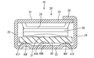
天井壁25は、図5に示すように、底壁22の上方に位置しており、天井壁25と底壁22は互いに対向する配置で平行に配設されている。天井壁25の一部は、下方に突出する形態とされており、この突出した部分は過度撓み防止部29とされている。過度撓み防止部29は、次述する弾性接触片30が天井壁25側に過度に撓んで塑性変形することを防止する役目を果たしている。
弾性接触片30は、図6に示すように、天井壁25の後縁から本体部21内に折り返されて前方に延出されている。弾性接触片30は、全体として略山形状をなしており、弾性接触片30の下端部には、第1接点31が下方に突出して設けられている。第1接点31は、弾性接触片30の前端寄りに位置しており、前述した過度撓み防止部29のやや前方に位置している。弾性接触片30は、相手端子60が本体部21内に挿入されたときに、第1接点31が相手端子60の上面に乗り上げることで第1接点31が底壁22から離間する方向に変位可能とされている。
弾性接触片30と過度撓み防止部29はいずれも、図5に示すように、天井壁25のほぼ全幅に亘って形成されている。このため、弾性接触片30が過度撓み防止部29に当接する際には、弾性接触片30が全幅に亘って過度撓み防止部29に当接することになる。これにより、例えば相手端子60が斜め方向に本体部21内に進入した際に、弾性接触片30が上方に押し込まれて塑性変形することを防止できるようになっている。このとき、弾性接触片30の上面が過度撓み防止部29の下面に面接触状態で当接するため、強固な力がかかっても広範囲に力を分散させることができ、弾性接触片30の過度撓みを防止することができる。
底壁22には、図5に示すように、3つの突出部が上方に突出して設けられており、このうち真ん中に位置する突出部が後側突出部40Rとされ、左右両側に位置する突出部が前側突出部40Fとされている。図6に示すように、前側突出部40Fは、第1接点31よりも前側に配設された前側接点41Fと、前側接点41Fから後方に向かうほど底壁22側に近づく斜面を有する前側ビード42Fとを備えて構成され、後側突出部40Rは、第1接点31よりも後側に配設された後側接点41Rと、後側接点41Rから前方に向かうほど底壁22側に近づく斜面を有する後側ビード42Rとを備えて構成されている。左側の前側突出部40Fは、左側壁23寄りに配設され、右側の前側突出部40Fは、右側壁24寄りに配設されている。このため、前側に位置する左右一対の前側接点41Fと第1接点31との間には、十分な離間距離が確保されており、相手端子60が第1接点31を中心として回転するために必要な回転モーメントが少しでも大きくなるように工夫されている。
図4に示すように、前側接点41Fは、半球の前側部分を残した形状とされている。同様に、後側接点41Rは、半球の後側部分を残した形状とされている。
前側ビード42Fと後側ビード42Rはともに前後方向に延びる形態をなし、互いに平行かつ独立に並んで配置され、前側ビード42Fの後端は、後側ビード42Rの前端よりも後方に位置している。より詳細には、前側ビード42Fの後端は、前後方向において後側接点41Rと同じ位置とされ、後側ビード42Rの前端は、前後方向において前側接点41Fと同じ位置とされている。
図6に示すように、前側ビード42Fと後側ビード42Rは、側面視において交差する形態とされており、相手端子60の先端が前側ビード42Fに沿って後方へ案内されると、底壁22よりも上方で後側ビード42Rに乗り移り、後側ビード42Rに沿って後方へ案内されることになるため、相手端子60の挿入動作を円滑に行うことができる。したがって、相手端子60の先端が底壁22に落ち込んで後側接点41Rに突き当たることで挿入力が高くなることはないものとされている。
図6に示すように、第1接点31の前後方向に占める領域FR1は、前側突出部40Fの前端から後側突出部40Rの後端までの領域FR2の範囲内に位置するものとされている。これは、図7に示すように、相手端子60が本体部21内に挿入されたときに、第1接点31が相手端子60の上面に乗り上げることで相手端子60が下方に押し込まれると、相手端子60が前後2箇所の接点41F、41Rによって支持されることを意味している。このようにすれば、相手端子60の前端が上方もしくは下方に傾いた姿勢をとろうとしても、元の水平姿勢に矯正されるため、相手端子60のぐらつきをなくすことができる。
また、図8に示すように、第1接点31の左右方向に占める領域LR1は、左側に位置する前側突出部40Fの左端から右側に位置する前側突出部40Fの右端までの領域LR2の範囲内に位置するものとされている。これは、図9に示すように、相手端子60が本体部21内に挿入されたときに、第1接点31が相手端子60の上面に乗り上げることで相手端子60が下方に押し込まれると、相手端子60が左右2箇所の前側接点41Fによって支持されることを意味している。このようにすれば、相手端子60の左端が上方もしくは下方に傾いた姿勢(もしくは相手端子60の右端が上方もしくは下方に傾いた姿勢)をとろうとしても、元の水平姿勢に矯正されるため、相手端子60のぐらつきをなくすことができる。
このようにしておけば、第1接点31から受ける力によって相手端子60が底壁22側に押し込まれた際に、相手端子60が3つの接点41F、41Rによって必ず支持されることになる。このため、相手端子60は、常には、弾性接触片30の第1接点31と、底壁22の3つの接点41F、41Rとによって弾性的に挟持されることになり、接点位置を明確にすることができる。
以上のように本実施形態では、相手端子60が本体部21内に嵌合した際に、第1壁部(天井壁25)の弾性接触片30と第2壁部(底壁22)の3つの突出部40F、40Rとの間に相手端子60が挟持されることになる。このとき、弾性接触片30から受ける力によって相手端子60が3つの突出部40F、40Rに接触した3点接触になるから、接点位置と接点数が一定になる。
また、相手端子60を本体部21内に挿入する際には、相手端子60の先端が前側ビード42Fと後側ビード42Rとによって後方へ案内されるため、相手端子60の先端が後側接点41Rに突き当たることで操作力が高くなることはない。
前側ビード42Fと後側ビード42Rはともに前後方向に延びる形態をなし、前側ビード42Fの後端は、後側ビード42Rの前端よりも後方に位置している構成としてもよい。
このような構成によると、相手端子60の先端が前側ビード42Fから後側ビード42Rに乗り移るから、相手端子60の挿入動作を円滑に行うことができる。
このような構成によると、相手端子60の先端が前側ビード42Fから後側ビード42Rに乗り移るから、相手端子60の挿入動作を円滑に行うことができる。
前側突出部40Fは2つ設けられ、後側突出部40Rは1つ設けられている構成としてもよい。
このような構成によると、相手端子60を本体部21内に挿入した直後に、相手端子60が2つの前側ビード42Fによって支持されるから、挿入初期から相手端子60のぐらつきをなくすことができる。
このような構成によると、相手端子60を本体部21内に挿入した直後に、相手端子60が2つの前側ビード42Fによって支持されるから、挿入初期から相手端子60のぐらつきをなくすことができる。
<他の実施形態>
本明細書によって開示される技術は上記記述及び図面によって説明した実施形態に限定されるものではなく、例えば次のような種々の態様も含まれる。
(1)上記実施形態では4つの壁部からなる角筒形の本体部21を例示しているものの、第1壁部と第2壁部を含む本体部であれば他の形態でもよく、5つの壁部からなる角筒形の本体部としてもよい。
本明細書によって開示される技術は上記記述及び図面によって説明した実施形態に限定されるものではなく、例えば次のような種々の態様も含まれる。
(1)上記実施形態では4つの壁部からなる角筒形の本体部21を例示しているものの、第1壁部と第2壁部を含む本体部であれば他の形態でもよく、5つの壁部からなる角筒形の本体部としてもよい。
(2)上記実施形態では底壁22に2つの前側接点41Fと1つの後側接点41Rとが配設されているものの、底壁22に1つの前側接点と2つの後側接点とを配設してもよい。
(3)上記実施形態では天井壁25の後縁から本体部21内に折り返す形態で弾性接触片30が設けられているものの、天井壁25の前縁から本体部21内に折り返す形態で弾性接触片を設けてもよいし、底壁22側に弾性接触片を設けてもよい。
(4)上記実施形態では各ビード42F、42Rが独立して設けられているものの、例えば前側接点41Fと後側接点41Rを連結する形態で、前側ビード42Fと後側ビード42Rを一体的に設けてもよい。
10…端子
21…本体部
22…底壁(第2壁部)
23…左側壁(第3壁部)
24…右側壁(第4壁部)
25…天井壁(第1壁部)
30…弾性接触片
31…第1接点
40F…前側突出部
40R…後側突出部
41F…前側接点
41R…後側接点
42F…前側ビード
42R…後側ビード
60…相手端子
21…本体部
22…底壁(第2壁部)
23…左側壁(第3壁部)
24…右側壁(第4壁部)
25…天井壁(第1壁部)
30…弾性接触片
31…第1接点
40F…前側突出部
40R…後側突出部
41F…前側接点
41R…後側接点
42F…前側ビード
42R…後側ビード
60…相手端子
Claims (3)
- 第1壁部と前記第1壁部に対向して配設された第2壁部とを有し、全体として角筒形をなす本体部と、
前記第1壁部の前縁もしくは後縁から前記本体部内に延出され、前記第2壁部側に突出して設けられた第1接点を有し、前記第1接点が前記第2壁部から離間する方向に変位可能とされた弾性接触片と、
前記第2壁部から前記第1壁部側に突出して設けられ、前側突出部と後側突出部を含んで構成される3つの突出部とを備え、
前記前側突出部は、前記第1接点よりも前側に配設された前側接点と、前記前側接点から後方に向かうほど前記第2壁部側に近づく斜面を有する前側ビードとを備えて構成され、
前記後側突出部は、前記第1接点よりも後側に配設された後側接点と、前記後側接点から前方に向かうほど前記第2壁部側に近づく斜面を有する後側ビードとを備えて構成されている端子。 - 前記前側ビードと前記後側ビードはともに前後方向に延びる形態をなし、前記前側ビードの後端は、前記後側ビードの前端よりも後方に位置している請求項1に記載の端子。
- 前記前側突出部は2つ設けられ、前記後側突出部は1つ設けられている請求項1または請求項2に記載の端子。
Priority Applications (2)
| Application Number | Priority Date | Filing Date | Title |
|---|---|---|---|
| CN201780028628.4A CN109075481B (zh) | 2016-05-12 | 2017-04-21 | 端子 |
| US16/097,690 US10381764B2 (en) | 2016-05-12 | 2017-04-21 | Terminal |
Applications Claiming Priority (2)
| Application Number | Priority Date | Filing Date | Title |
|---|---|---|---|
| JP2016-095878 | 2016-05-12 | ||
| JP2016095878A JP6607141B2 (ja) | 2016-05-12 | 2016-05-12 | 端子 |
Publications (1)
| Publication Number | Publication Date |
|---|---|
| WO2017195569A1 true WO2017195569A1 (ja) | 2017-11-16 |
Family
ID=60267078
Family Applications (1)
| Application Number | Title | Priority Date | Filing Date |
|---|---|---|---|
| PCT/JP2017/015995 Ceased WO2017195569A1 (ja) | 2016-05-12 | 2017-04-21 | 端子 |
Country Status (4)
| Country | Link |
|---|---|
| US (1) | US10381764B2 (ja) |
| JP (1) | JP6607141B2 (ja) |
| CN (1) | CN109075481B (ja) |
| WO (1) | WO2017195569A1 (ja) |
Cited By (1)
| Publication number | Priority date | Publication date | Assignee | Title |
|---|---|---|---|---|
| CN110858686A (zh) * | 2018-08-22 | 2020-03-03 | 泰连德国有限公司 | 接触组件 |
Families Citing this family (4)
| Publication number | Priority date | Publication date | Assignee | Title |
|---|---|---|---|---|
| JP7165306B2 (ja) * | 2019-06-11 | 2022-11-04 | 株式会社オートネットワーク技術研究所 | 端子、及び、端子付き電線 |
| JP7218718B2 (ja) * | 2019-12-20 | 2023-02-07 | 住友電装株式会社 | 端子金具およびコネクタ |
| JP7495671B2 (ja) * | 2021-03-04 | 2024-06-05 | 株式会社オートネットワーク技術研究所 | 端子ユニット,雌端子,雄端子 |
| JP7543948B2 (ja) * | 2021-03-04 | 2024-09-03 | 株式会社オートネットワーク技術研究所 | 端子ユニットおよび端子ユニットにおいて用いられる雌端子 |
Citations (4)
| Publication number | Priority date | Publication date | Assignee | Title |
|---|---|---|---|---|
| JPH10247539A (ja) * | 1998-04-16 | 1998-09-14 | Sumitomo Wiring Syst Ltd | 雌形端子金具と雄形端子金具との接続構造 |
| JP2002063961A (ja) * | 2000-06-07 | 2002-02-28 | Yazaki Corp | 雌端子、及び、雌端子と雄端子との接続構造 |
| WO2011125727A1 (ja) * | 2010-03-31 | 2011-10-13 | 古河電気工業株式会社 | 雌型端子 |
| JP2014093197A (ja) * | 2012-11-02 | 2014-05-19 | Yazaki Corp | 雌端子及びその成形方法 |
Family Cites Families (18)
| Publication number | Priority date | Publication date | Assignee | Title |
|---|---|---|---|---|
| JPH0935795A (ja) * | 1995-07-18 | 1997-02-07 | Sumitomo Wiring Syst Ltd | 雌形端子金具およびその製造方法 |
| JP3494347B2 (ja) * | 1998-03-06 | 2004-02-09 | 矢崎総業株式会社 | 端子のへたり防止構造 |
| JP3529026B2 (ja) * | 1998-04-15 | 2004-05-24 | 矢崎総業株式会社 | 雌端子 |
| JP3473521B2 (ja) * | 1999-10-08 | 2003-12-08 | 住友電装株式会社 | 雌端子金具 |
| JP3480707B2 (ja) * | 2000-01-28 | 2003-12-22 | 住友電装株式会社 | 雌端子金具 |
| JP2003331968A (ja) * | 2002-05-13 | 2003-11-21 | Sumitomo Wiring Syst Ltd | 雌側端子金具 |
| US7261701B2 (en) | 2002-10-03 | 2007-08-28 | 3M Innovative Properties Co. | Skin antiseptic composition dispenser and methods of use |
| JP4678341B2 (ja) * | 2006-06-21 | 2011-04-27 | 住友電装株式会社 | 雌端子金具 |
| JP2013098088A (ja) * | 2011-11-02 | 2013-05-20 | Sumitomo Wiring Syst Ltd | 雌型端子金具 |
| JP6097072B2 (ja) * | 2012-12-27 | 2017-03-15 | 日本航空電子工業株式会社 | コネクタ |
| JP5955448B2 (ja) * | 2013-02-12 | 2016-07-20 | 矢崎総業株式会社 | コネクタ |
| CN103746206A (zh) * | 2013-12-31 | 2014-04-23 | 温州市珠城电气有限公司 | 旗形夹形自锁端子 |
| JP2015204186A (ja) | 2014-04-14 | 2015-11-16 | 矢崎総業株式会社 | 端子 |
| US9537227B1 (en) * | 2015-12-17 | 2017-01-03 | Delphi Technologies, Inc. | Female electrical terminal and method of manufacturing the same |
| JP6619287B2 (ja) * | 2016-04-14 | 2019-12-11 | 日本航空電子工業株式会社 | コネクタ端子 |
| JP6591341B2 (ja) * | 2016-04-21 | 2019-10-16 | 日本航空電子工業株式会社 | コネクタ端子 |
| US10090608B2 (en) * | 2016-09-29 | 2018-10-02 | Delphi Technologies, Inc. | Electrical connection system having a terminal with contact ridges |
| JP2019029216A (ja) * | 2017-07-31 | 2019-02-21 | 住友電装株式会社 | 雌端子 |
-
2016
- 2016-05-12 JP JP2016095878A patent/JP6607141B2/ja not_active Expired - Fee Related
-
2017
- 2017-04-21 WO PCT/JP2017/015995 patent/WO2017195569A1/ja not_active Ceased
- 2017-04-21 US US16/097,690 patent/US10381764B2/en active Active
- 2017-04-21 CN CN201780028628.4A patent/CN109075481B/zh not_active Expired - Fee Related
Patent Citations (4)
| Publication number | Priority date | Publication date | Assignee | Title |
|---|---|---|---|---|
| JPH10247539A (ja) * | 1998-04-16 | 1998-09-14 | Sumitomo Wiring Syst Ltd | 雌形端子金具と雄形端子金具との接続構造 |
| JP2002063961A (ja) * | 2000-06-07 | 2002-02-28 | Yazaki Corp | 雌端子、及び、雌端子と雄端子との接続構造 |
| WO2011125727A1 (ja) * | 2010-03-31 | 2011-10-13 | 古河電気工業株式会社 | 雌型端子 |
| JP2014093197A (ja) * | 2012-11-02 | 2014-05-19 | Yazaki Corp | 雌端子及びその成形方法 |
Cited By (1)
| Publication number | Priority date | Publication date | Assignee | Title |
|---|---|---|---|---|
| CN110858686A (zh) * | 2018-08-22 | 2020-03-03 | 泰连德国有限公司 | 接触组件 |
Also Published As
| Publication number | Publication date |
|---|---|
| CN109075481B (zh) | 2019-11-05 |
| CN109075481A (zh) | 2018-12-21 |
| US10381764B2 (en) | 2019-08-13 |
| US20190157786A1 (en) | 2019-05-23 |
| JP2017204397A (ja) | 2017-11-16 |
| JP6607141B2 (ja) | 2019-11-20 |
Similar Documents
| Publication | Publication Date | Title |
|---|---|---|
| JP6607141B2 (ja) | 端子 | |
| WO2017195568A1 (ja) | 端子 | |
| US9761977B2 (en) | Conductive terminal and electrical connector | |
| US8795007B2 (en) | Terminal fitting | |
| US9490563B2 (en) | Female connector with improved contact area | |
| US7686662B2 (en) | Electrical connector assembly | |
| JP6780571B2 (ja) | 端子金具 | |
| CN105210239B (zh) | 阴端子接头 | |
| US20180316112A1 (en) | Terminal | |
| US10270197B2 (en) | Female terminal having a resiliently displaceable contact piece folded rearward from a front end of a step | |
| US20190036259A1 (en) | Female terminal | |
| CN1815816B (zh) | 端子接头、设置有该端子接头的连接器及形成该端子接头的方法 | |
| TWI715199B (zh) | 連接器及端子 | |
| JP6124074B2 (ja) | 雌端子 | |
| KR101665473B1 (ko) | 단자 | |
| US9559460B2 (en) | Lever-type connector with regulating protrusion on male housing that engages lever on female housing to achieve connection without inclination between male and female housings | |
| JP2006228759A (ja) | 雌側端子金具 | |
| JP6447272B2 (ja) | 端子金具 | |
| CN101005171B (zh) | 端子接头及设置有该端子接头的连接器 | |
| KR101666301B1 (ko) | 수단자 금구 | |
| US10559897B1 (en) | Push-in electrical terminal with insulation contact | |
| JP2006216313A (ja) | 端子金具 | |
| JP2021057184A (ja) | 雄端子、および雄コネクタ | |
| JP2006216306A (ja) | 端子金具 | |
| JP2004014477A (ja) | 雌側端子金具 |
Legal Events
| Date | Code | Title | Description |
|---|---|---|---|
| NENP | Non-entry into the national phase |
Ref country code: DE |
|
| 121 | Ep: the epo has been informed by wipo that ep was designated in this application |
Ref document number: 17795930 Country of ref document: EP Kind code of ref document: A1 |
|
| 122 | Ep: pct application non-entry in european phase |
Ref document number: 17795930 Country of ref document: EP Kind code of ref document: A1 |