WO2017191852A1 - フィルタ状態推定システムおよびフィルタ状態の推定方法 - Google Patents
フィルタ状態推定システムおよびフィルタ状態の推定方法 Download PDFInfo
- Publication number
- WO2017191852A1 WO2017191852A1 PCT/JP2017/022363 JP2017022363W WO2017191852A1 WO 2017191852 A1 WO2017191852 A1 WO 2017191852A1 JP 2017022363 W JP2017022363 W JP 2017022363W WO 2017191852 A1 WO2017191852 A1 WO 2017191852A1
- Authority
- WO
- WIPO (PCT)
- Prior art keywords
- filter
- valve
- state
- temperature
- oil
- Prior art date
- Legal status (The legal status is an assumption and is not a legal conclusion. Google has not performed a legal analysis and makes no representation as to the accuracy of the status listed.)
- Ceased
Links
Images






Classifications
-
- B—PERFORMING OPERATIONS; TRANSPORTING
- B01—PHYSICAL OR CHEMICAL PROCESSES OR APPARATUS IN GENERAL
- B01D—SEPARATION
- B01D35/00—Filtering devices having features not specifically covered by groups B01D24/00 - B01D33/00, or for applications not specifically covered by groups B01D24/00 - B01D33/00; Auxiliary devices for filtration; Filter housing constructions
- B01D35/14—Safety devices specially adapted for filtration; Devices for indicating clogging
- B01D35/143—Filter condition indicators
-
- B—PERFORMING OPERATIONS; TRANSPORTING
- B01—PHYSICAL OR CHEMICAL PROCESSES OR APPARATUS IN GENERAL
- B01D—SEPARATION
- B01D29/00—Filters with filtering elements stationary during filtration, e.g. pressure or suction filters, not covered by groups B01D24/00 - B01D27/00; Filtering elements therefor
- B01D29/11—Filters with filtering elements stationary during filtration, e.g. pressure or suction filters, not covered by groups B01D24/00 - B01D27/00; Filtering elements therefor with bag, cage, hose, tube, sleeve or like filtering elements
- B01D29/114—Filters with filtering elements stationary during filtration, e.g. pressure or suction filters, not covered by groups B01D24/00 - B01D27/00; Filtering elements therefor with bag, cage, hose, tube, sleeve or like filtering elements arranged for inward flow filtration
-
- B—PERFORMING OPERATIONS; TRANSPORTING
- B01—PHYSICAL OR CHEMICAL PROCESSES OR APPARATUS IN GENERAL
- B01D—SEPARATION
- B01D29/00—Filters with filtering elements stationary during filtration, e.g. pressure or suction filters, not covered by groups B01D24/00 - B01D27/00; Filtering elements therefor
- B01D29/60—Filters with filtering elements stationary during filtration, e.g. pressure or suction filters, not covered by groups B01D24/00 - B01D27/00; Filtering elements therefor integrally combined with devices for controlling the filtration
- B01D29/608—Filters with filtering elements stationary during filtration, e.g. pressure or suction filters, not covered by groups B01D24/00 - B01D27/00; Filtering elements therefor integrally combined with devices for controlling the filtration by temperature measuring
-
- B—PERFORMING OPERATIONS; TRANSPORTING
- B01—PHYSICAL OR CHEMICAL PROCESSES OR APPARATUS IN GENERAL
- B01D—SEPARATION
- B01D35/00—Filtering devices having features not specifically covered by groups B01D24/00 - B01D33/00, or for applications not specifically covered by groups B01D24/00 - B01D33/00; Auxiliary devices for filtration; Filter housing constructions
- B01D35/02—Filters adapted for location in special places, e.g. pipe-lines, pumps, stop-cocks
-
- B—PERFORMING OPERATIONS; TRANSPORTING
- B01—PHYSICAL OR CHEMICAL PROCESSES OR APPARATUS IN GENERAL
- B01D—SEPARATION
- B01D35/00—Filtering devices having features not specifically covered by groups B01D24/00 - B01D33/00, or for applications not specifically covered by groups B01D24/00 - B01D33/00; Auxiliary devices for filtration; Filter housing constructions
- B01D35/14—Safety devices specially adapted for filtration; Devices for indicating clogging
- B01D35/147—Bypass or safety valves
-
- B—PERFORMING OPERATIONS; TRANSPORTING
- B01—PHYSICAL OR CHEMICAL PROCESSES OR APPARATUS IN GENERAL
- B01D—SEPARATION
- B01D35/00—Filtering devices having features not specifically covered by groups B01D24/00 - B01D33/00, or for applications not specifically covered by groups B01D24/00 - B01D33/00; Auxiliary devices for filtration; Filter housing constructions
- B01D35/14—Safety devices specially adapted for filtration; Devices for indicating clogging
- B01D35/147—Bypass or safety valves
- B01D35/1475—Pressure relief valves or pressure control valves
-
- E—FIXED CONSTRUCTIONS
- E02—HYDRAULIC ENGINEERING; FOUNDATIONS; SOIL SHIFTING
- E02F—DREDGING; SOIL-SHIFTING
- E02F9/00—Component parts of dredgers or soil-shifting machines, not restricted to one of the kinds covered by groups E02F3/00 - E02F7/00
- E02F9/20—Drives; Control devices
- E02F9/2025—Particular purposes of control systems not otherwise provided for
-
- E—FIXED CONSTRUCTIONS
- E02—HYDRAULIC ENGINEERING; FOUNDATIONS; SOIL SHIFTING
- E02F—DREDGING; SOIL-SHIFTING
- E02F9/00—Component parts of dredgers or soil-shifting machines, not restricted to one of the kinds covered by groups E02F3/00 - E02F7/00
- E02F9/20—Drives; Control devices
- E02F9/22—Hydraulic or pneumatic drives
- E02F9/2278—Hydraulic circuits
- E02F9/2282—Systems using center bypass type changeover valves
-
- E—FIXED CONSTRUCTIONS
- E02—HYDRAULIC ENGINEERING; FOUNDATIONS; SOIL SHIFTING
- E02F—DREDGING; SOIL-SHIFTING
- E02F9/00—Component parts of dredgers or soil-shifting machines, not restricted to one of the kinds covered by groups E02F3/00 - E02F7/00
- E02F9/26—Indicating devices
- E02F9/267—Diagnosing or detecting failure of vehicles
-
- F—MECHANICAL ENGINEERING; LIGHTING; HEATING; WEAPONS; BLASTING
- F15—FLUID-PRESSURE ACTUATORS; HYDRAULICS OR PNEUMATICS IN GENERAL
- F15B—SYSTEMS ACTING BY MEANS OF FLUIDS IN GENERAL; FLUID-PRESSURE ACTUATORS, e.g. SERVOMOTORS; DETAILS OF FLUID-PRESSURE SYSTEMS, NOT OTHERWISE PROVIDED FOR
- F15B21/00—Common features of fluid actuator systems; Fluid-pressure actuator systems or details thereof, not covered by any other group of this subclass
- F15B21/04—Special measures taken in connection with the properties of the fluid
- F15B21/041—Removal or measurement of solid or liquid contamination, e.g. filtering
-
- B—PERFORMING OPERATIONS; TRANSPORTING
- B01—PHYSICAL OR CHEMICAL PROCESSES OR APPARATUS IN GENERAL
- B01D—SEPARATION
- B01D2201/00—Details relating to filtering apparatus
- B01D2201/26—Transport systems for filtering devices
- B01D2201/265—Transport systems for filtering devices mounted on vehicles
-
- E—FIXED CONSTRUCTIONS
- E02—HYDRAULIC ENGINEERING; FOUNDATIONS; SOIL SHIFTING
- E02F—DREDGING; SOIL-SHIFTING
- E02F3/00—Dredgers; Soil-shifting machines
- E02F3/04—Dredgers; Soil-shifting machines mechanically-driven
- E02F3/28—Dredgers; Soil-shifting machines mechanically-driven with digging tools mounted on a dipper- or bucket-arm, i.e. there is either one arm or a pair of arms, e.g. dippers, buckets
- E02F3/30—Dredgers; Soil-shifting machines mechanically-driven with digging tools mounted on a dipper- or bucket-arm, i.e. there is either one arm or a pair of arms, e.g. dippers, buckets with a dipper-arm pivoted on a cantilever beam, i.e. boom
- E02F3/32—Dredgers; Soil-shifting machines mechanically-driven with digging tools mounted on a dipper- or bucket-arm, i.e. there is either one arm or a pair of arms, e.g. dippers, buckets with a dipper-arm pivoted on a cantilever beam, i.e. boom working downwardly and towards the machine, e.g. with backhoes
-
- F—MECHANICAL ENGINEERING; LIGHTING; HEATING; WEAPONS; BLASTING
- F15—FLUID-PRESSURE ACTUATORS; HYDRAULICS OR PNEUMATICS IN GENERAL
- F15B—SYSTEMS ACTING BY MEANS OF FLUIDS IN GENERAL; FLUID-PRESSURE ACTUATORS, e.g. SERVOMOTORS; DETAILS OF FLUID-PRESSURE SYSTEMS, NOT OTHERWISE PROVIDED FOR
- F15B19/00—Testing; Calibrating; Fault detection or monitoring; Simulation or modelling of fluid-pressure systems or apparatus not otherwise provided for
- F15B19/005—Fault detection or monitoring
-
- F—MECHANICAL ENGINEERING; LIGHTING; HEATING; WEAPONS; BLASTING
- F15—FLUID-PRESSURE ACTUATORS; HYDRAULICS OR PNEUMATICS IN GENERAL
- F15B—SYSTEMS ACTING BY MEANS OF FLUIDS IN GENERAL; FLUID-PRESSURE ACTUATORS, e.g. SERVOMOTORS; DETAILS OF FLUID-PRESSURE SYSTEMS, NOT OTHERWISE PROVIDED FOR
- F15B2211/00—Circuits for servomotor systems
- F15B2211/60—Circuit components or control therefor
- F15B2211/615—Filtering means
-
- F—MECHANICAL ENGINEERING; LIGHTING; HEATING; WEAPONS; BLASTING
- F15—FLUID-PRESSURE ACTUATORS; HYDRAULICS OR PNEUMATICS IN GENERAL
- F15B—SYSTEMS ACTING BY MEANS OF FLUIDS IN GENERAL; FLUID-PRESSURE ACTUATORS, e.g. SERVOMOTORS; DETAILS OF FLUID-PRESSURE SYSTEMS, NOT OTHERWISE PROVIDED FOR
- F15B2211/00—Circuits for servomotor systems
- F15B2211/60—Circuit components or control therefor
- F15B2211/63—Electronic controllers
- F15B2211/6303—Electronic controllers using input signals
- F15B2211/634—Electronic controllers using input signals representing a state of a valve
-
- F—MECHANICAL ENGINEERING; LIGHTING; HEATING; WEAPONS; BLASTING
- F15—FLUID-PRESSURE ACTUATORS; HYDRAULICS OR PNEUMATICS IN GENERAL
- F15B—SYSTEMS ACTING BY MEANS OF FLUIDS IN GENERAL; FLUID-PRESSURE ACTUATORS, e.g. SERVOMOTORS; DETAILS OF FLUID-PRESSURE SYSTEMS, NOT OTHERWISE PROVIDED FOR
- F15B2211/00—Circuits for servomotor systems
- F15B2211/60—Circuit components or control therefor
- F15B2211/63—Electronic controllers
- F15B2211/6303—Electronic controllers using input signals
- F15B2211/6343—Electronic controllers using input signals representing a temperature
Definitions
- the present invention relates to a filter state estimation system and a filter state estimation method.
- the oil stored in the hydraulic oil tank is supplied to the hydraulic actuator by a hydraulic pump, and then activated again. Returned to the oil tank.
- the hydraulic oil tank is provided with an oil filter device, and the oil returned from the hydraulic actuator is filtered by the oil filter and stored in the hydraulic oil tank (see, for example, Patent Document 1).
- the filter element is housed in the filter case, and the oil flowing in from the suction port of the filter case passes through the filter medium of the filter element until the foreign matter contained in the oil is discharged from the discharge port. Removed.
- the filter element used in the oil filter device has a problem that every time foreign matter is removed, the filter medium is clogged, and the oil gradually becomes difficult to pass through the filter element.
- a bypass flow path is provided to connect the front and rear of the filter element, a valve is provided in the bypass flow path, and when the differential pressure across the filter element exceeds a predetermined value, the bypass flow path valve is opened.
- a technique for notifying an operator of clogging of a filter element while maintaining the flow of hydraulic oil is known (see, for example, Patent Document 2 and Patent Document 3).
- An object of the present invention is to provide a filter state estimation system and a filter state capable of estimating the state of a filter element (hereinafter also referred to as a filter in this specification) when a valve in the bypass flow path is opened. It is to provide an estimation method.
- a filter state estimation system is a filter state estimation system that estimates a state of a filter provided in a hydraulic circuit, and the hydraulic circuit includes a filter and a bypass channel through which oil flows around the filter.
- a valve provided in the bypass flow path that opens and closes based on a differential pressure, detects the opening and closing of the valve, a temperature sensor that detects the temperature of oil, and is detected by the sensor and the temperature sensor
- a state estimation unit that estimates the state of the filter based on the detected result, and the state estimation unit is detected by the temperature sensor when the sensor detects that the valve is open.
- the state of the filter is estimated based on the temperature of the oil that has been applied.
- the temperature of the oil is detected by the temperature sensor when the opening sensor detects that the valve is open. Therefore, when the valve of the bypass channel is opened, it is possible to estimate the clogged state of the filter according to the temperature of the oil, and to predict the life of the filter and determine that the filter has been replaced.
- the perspective view which shows the construction machine which concerns on 1st Embodiment of this invention The schematic diagram which shows the hydraulic circuit of the construction machine in the said embodiment. Sectional drawing which shows the structure of the oil filter apparatus in the said embodiment.
- the functional block diagram of the controller and server in the said embodiment The schematic diagram which shows the state estimation table in the said embodiment.
- the schematic diagram which shows the maximum oil temperature time series data in the said embodiment The schematic diagram for demonstrating the lifetime prediction in the said embodiment.
- the flowchart which shows the estimation method of the filter state in the said embodiment.
- FIG. 1 shows a hydraulic excavator 1 according to an embodiment of the present invention.
- the hydraulic excavator 1 as a construction machine includes a lower traveling body 2, an upper swing body 3, and a work implement 5.
- the lower traveling body 2 includes a track frame and a pair of traveling devices 2A provided at both ends in the vehicle width direction perpendicular to the traveling direction of the track frame.
- the traveling device 2A includes a crawler belt 2B wound around a driving wheel and an idler wheel provided on the track frame, and drives the driving wheel to move the hydraulic excavator 1 forward and backward in the extending direction of the crawler belt 2B.
- the upper swing body 3 is provided on the track frame of the lower traveling body 2 so as to be swingable via a swing circle.
- a cab 4 is provided on the left side in the traveling direction of the upper swing body 3, and a work implement 5 is provided in the center of the front part adjacent to the cab 4.
- a counterweight 3 ⁇ / b> A is provided at a rear portion of the upper swing body 3 on the side opposite to the cab 4 and the work machine 5.
- the counterweight 3A is provided to balance the weight during excavation work of the hydraulic excavator 1.
- An operator rides inside the cab 4 to drive the excavator 1.
- an operator seat is provided in the cab 4, and operation levers are provided on both sides of the operator seat.
- a traveling pedal is provided on the floor surface of the cab 4.
- the work machine 5 includes a boom 6, an arm 7, and a bucket 8, and a boom cylinder 6A, an arm cylinder 7A, and a bucket cylinder 8A for operating these elements.
- the base end of the boom 6 is operably connected to the upper swing body 3.
- the boom 6 is moved up and down by expanding and contracting the upper cylinder 3 and the boom cylinder 6 ⁇ / b> A whose tips are connected to the boom 6.
- the base end of the arm 7 is operably connected to the tip of the boom 6.
- the arm 7 is moved up and down by expanding and contracting the boom cylinder 6 and the arm cylinder 7A, the distal ends of which are connected to the arm 7.
- the bucket 8 has a base end of the bucket 8 operably connected to the arm 7 at the tip of the arm 7.
- the bucket 8 is operated by expanding and contracting a bucket cylinder 8A whose tips are connected to the arm 7 and the bucket 8, respectively.
- Boom cylinder 6A, arm cylinder 7A, and bucket cylinder 8A are hydraulic cylinders that are driven by hydraulic oil discharged from hydraulic pump 12 (see FIG. 2).
- FIG. 2 shows the hydraulic circuit 10 provided in the hydraulic excavator 1 of the present embodiment.
- the hydraulic circuit 10 includes a hydraulic oil tank 11, a hydraulic pump 12, an operation valve 13, and an oil filter device 14.
- the hydraulic oil tank 11 supplies the hydraulic oil to the hydraulic pump 12 and stores the return hydraulic oil that has driven the hydraulic cylinders 6A, 7A, and 8A.
- the hydraulic pump 12 sucks hydraulic oil from the hydraulic oil tank 11 and pumps the hydraulic oil to the operation valve 13.
- the operation valve 13 changes the position of the spool by operating an operation lever in the cab 4 (not shown), supplies hydraulic oil to the hydraulic cylinders 6A, 7A, and 8A that are actuators, and extends the hydraulic cylinders 6A, 7A, and 8A.
- the boom 6, the arm 7, and the bucket 8 are operated by causing the boom 6, the contraction, and the like.
- the hydraulic oil from the operation valve 13 may be supplied to a hydraulic motor that drives the hydraulic excavator 1. Then, the hydraulic oil discharged from the hydraulic motor returns to the hydraulic oil tank 11 via the operation valve 13.
- the operation valve 13 is also operated to return the return hydraulic oil from the hydraulic cylinders 6A, 7A, 8A to the hydraulic oil tank 11 via the oil filter device 14.
- the oil filter device 14 is provided in the return pipe from the operation valve 13 and removes foreign matters mixed in the hydraulic oil in the hydraulic circuit 10.
- the oil filter device 14 includes a filter element 15, a bypass channel 16 that bypasses the filter element 15, and a valve 17 that is provided in the middle of the bypass channel 16.
- the valve 17 is provided with a stroke sensor 18 as an opening sensor, and a detection value by the stroke sensor 18 is output to the controller 20.
- a temperature sensor 19 is provided at the suction port of the hydraulic pump 12, and a detection value by the temperature sensor 19 is output to the controller 20.
- the controller 20 as a control device outputs a control command to each part of the hydraulic circuit 10 and performs drive control of the hydraulic circuit 10.
- the controller 20 is communicably connected to the monitor 21 and the communication terminal 22 via a control area network (CAN).
- the monitor 21 includes a processing unit and a display unit.
- the display unit displays various data such as the temperature of engine coolant detected by a sensor or the like, the remaining amount of fuel, and the temperature of hydraulic oil.
- the communication terminal 22 outputs information such as a detection value detected by a sensor or the like, a setting value set by the monitor 21, a position of the hydraulic excavator 1 detected by the Global Positioning System (GPS) 23 to the outside.
- GPS Global Positioning System
- the communication terminal 22 outputs these pieces of information to the server 24 via a satellite communication line or a mobile communication network.
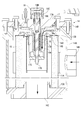
- FIG. 3 shows a detailed structure of the oil filter device 14.
- the oil filter device 14 includes a case main body 14A and a lid body 14B.
- the case body 14A is configured as a cylindrical container, and the filter element 15 is accommodated therein.
- a return oil suction port 141 as a suction portion is formed on the side surface of the case body 14A, a return pipe from the operation valve 13 is connected, and hydraulic oil returned from the operation valve 13 is supplied into the case body 14A.
- the A hole 142 as a discharge portion is formed at the center of the bottom portion of the case main body 14 ⁇ / b> A, and hydraulic oil from which foreign matter has been removed by the filter element 15 is supplied into the hydraulic oil tank 11.
- the lid 14B closes the upper surface of the case body 14A, and a valve 17 is attached to the center of the lid 14B.
- the valve 17 has a valve body 17A, and a coil spring 14C arranged coaxially with the cylindrical central axis of the case body 14A is provided at the lower part of the valve body 17A.
- the coil spring 14C urges the filter element 15 downward via the plate 14D, and fixes the filter element 15 in the case main body 14A.
- the filter element 15 includes a filter medium 15A formed in a hollow cylindrical shape, and plates 15B provided on both end surfaces of the filter medium 15A in the cylindrical axis direction.
- 15 A of filter media removes the foreign material in the hydraulic fluid which flows inside from the radial direction outer side.
- the plate 15B contacts the bottom of the case body 14A and the bottom surface of the plate 14D.
- the filter element 15 is maintained coaxially with the cylindrical axis of the case body 14A by being biased by the coil spring 14C.
- the filter element 15 is also referred to as a filter.
- the valve 17 includes a bypass passage 16 that allows the hydraulic oil outside the filter element 15 and the hydraulic fluid inside to communicate with each other, and a valve body 17C that opens and closes the bypass passage 16.
- the valve 17 includes a valve stem 17B, a valve main body 17C, and a coil spring 17D, and adjusts the flow rate of oil flowing through the bypass flow path 16.
- the valve stem 17B is made of a steel shaft-like member, is accommodated in the valve body 17A, and is supported so as to be slidable in the vertical direction with respect to the valve body 17A.
- the valve body 17C is a disc-shaped lid member attached to the lower end of the valve stem 17B.
- the valve body 17C closes the bypass flow path 16 and blocks the flow of hydraulic oil.
- the valve body 17C moves downward, a gap is formed and the hydraulic oil flows.
- the coil spring 17D is inserted into the valve stem 17B and urges the valve stem 17B to be lifted upward.
- a stroke sensor 18 is provided at the upper base end of the valve stem 17B.
- the stroke sensor 18 includes a movable part 18A including a magnet 18B and a sensor body 18C.
- the movable portion 18A is connected to the proximal end of the valve stem 17B and slides up and down as the valve stem 17B slides.
- the magnet 18B is provided at the upper end of the movable portion 18A, and moves up and down as the movable portion 18A slides up and down.
- the sensor body 18C is provided with a magnetically sensitive element, for example, a Hall IC, and detects a change in the magnetic field due to the vertical movement of the magnet 18B.
- valve stem 17B biased upward by the coil spring 17D is moved downward. To slide. Along with this, the valve body 17C moves downward, and the hydraulic oil that has passed through the bypass passage 16 is discharged from the hole 142.
- the movable portion 18A of the stroke sensor 18 also slides downward simultaneously. The sensor body 18C of the stroke sensor 18 detects this and outputs an electrical signal to inform the controller 20 that the valve 17 is open.
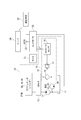
- FIG. 4 shows a functional block diagram of the controller 20 and server 24.
- the controller 20 acquires detection data of various sensors provided in the excavator 1.
- the controller 20 includes a hydraulic oil temperature acquisition unit 201, a valve opening / closing state acquisition unit 202, a position information acquisition unit 203, and an operation information acquisition unit 204.
- the hydraulic oil temperature acquisition unit 201 acquires temperature detection data from the temperature sensor 19 provided in the hydraulic oil tank 11.
- the valve opening / closing state acquisition unit 202 acquires detection data of the opening / closing state of the valve 17 by the stroke sensor 18 and detects opening / closing of the valve 17. Specifically, the valve open / close state acquisition unit 202 opens the valve 17 based on whether or not the time during which the stroke amount detected by the stroke sensor 18 exceeds a predetermined threshold continues for a predetermined time. Get the state.
- the position information acquisition unit 203 acquires the current position of the excavator 1 detected by the GPS 23.
- the operation information acquisition unit 204 acquires detection data from various sensors provided in the excavator 1 and acquires operation information of the excavator 1.
- the operation information includes, for example, engine cooling water temperature, fuel remaining amount, operation time of the hydraulic excavator 1, operating fuel consumption, and the like.
- the controller 20 outputs the acquired hydraulic oil temperature, the open / close state of the valve 17, and the operation information of the hydraulic excavator 1 to the communication terminal 22.
- the server 24 accepts various information output from the communication terminal 22 and stores and saves it.
- the server 24 includes a memory 24A, a data storage unit 240, a state estimation unit 241, a life prediction unit 242, and a replacement presence / absence determination unit 243.
- the memory 24A stores various table data described later.
- the state estimation unit 241 estimates the clogged state of the filter element 15 based on the maximum oil temperature when the valve 17 is open. Specifically, as shown in FIG. 5, the state estimation unit 241 refers to a state estimation table that gives a relationship between the maximum oil temperature in the valve open state and the clogging rate of the filter element 15, and opens the valve 17.
- the clogging rate of the filter element 15 is estimated from the maximum oil temperature in the state.
- the maximum oil temperature in the opened state of the valve 17 means the highest hydraulic oil temperature when the hydraulic oil temperature in the opened state of the valve 17 is detected at any time and viewed within a certain elapsed time, for example, 10 hours. .
- the differential pressure since the oil viscosity is usually low at high temperatures, the differential pressure is unlikely to rise. However, as the filter element 15 becomes clogged, the differential pressure will rise even at high temperatures.
- the data storage unit 240 stores the maximum oil temperature data in the open state of the valve 17 in a time series as shown in FIG. 6 and outputs the result to the life prediction unit 242 and the replacement presence / absence determination unit 243.
- the life prediction unit 242 predicts the life of the filter element 15 based on the transition of the state of the filter element 15 in the open state of the valve 17 from the monitoring result of the maximum oil temperature of the state estimation unit 241.
- the filter life is that the maximum oil temperature in the open state of the valve 17 at the present time and the maximum oil temperature in the open state of the valve 17 in the vicinity of the current time change with time, so that the maximum oil temperature in the open state of the valve 17 is the clogging alarm level. For example, a time for reaching 40 ° C. is obtained and estimated.
- the life of the filter element 15 at the time t1 in FIG. 7A is calculated by extrapolating the time t2 when the oil temperature reaches the clogging warning alarm temperature from the amount of change in the maximum oil temperature at the time t1 and the time t0 near the time t1.
- the time T_remain from time t1 to time t2 is estimated as the life of the filter element 15.
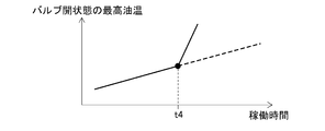
- the life prediction unit 242 determines that an abnormality has occurred in the filter element 15 when a sudden change occurs in the maximum oil temperature in the open state of the valve 17 as in the case of time t4. To do.
- the replacement presence / absence determination unit 243 determines whether or not the filter element 15 is replaced based on the maximum oil temperature time-series data in the valve open state by the data storage unit 240. Specifically, it is determined that the filter element 15 has been replaced when the maximum oil temperature in the open state of the valve 17 suddenly drops below a certain value. For example, in the case of FIG. 6, it is determined that the time t3 and the time t5 are times when the filter element 15 is replaced. When a predetermined operating time (for example, 1000 hours) elapses due to the replacement of the filter element 15, a message prompting the replacement of the filter element 15 is displayed on the monitor 21 or the like. In addition, on the monitor 21 or the like, the exchange time is displayed as a past history.
- a predetermined operating time for example, 1000 hours
- the controller 20 determines whether or not the maximum oil temperature in the opened state of the valve 17, the duration of the opened state of the valve 17, and the closed position of the valve 17 are initialized (procedure S 1). If it has been initialized (S1: Yes), the process proceeds to step S3.
- the hydraulic oil temperature acquisition unit 201 initializes the maximum oil temperature T_max in the open state of the valve 17 to, for example, ⁇ 100 ° C., and the valve open / close state acquisition unit 202 sets the valve open state.
- the state duration time OpenTime is initialized to 0 seconds, and the valve stroke closing position L_0 is initialized to 0 mm (step S2).
- the controller 20 determines whether or not the time after engine startup exceeds the processing start determination time (for example, 3 minutes) (step S3). If the process start determination time has not been exceeded (S3: No), the process ends.
- the valve opening / closing state acquisition unit 202 measures the stroke L of the valve 17 by the stroke sensor 18 (step S4).
- the valve opening / closing state acquisition unit 202 determines whether or not the operation lever is in a neutral state (step S5). When the operation lever is not in the neutral state (S5: No), the process proceeds to step S7.
- the valve opening / closing state acquisition unit 202 automatically corrects the valve stroke closed position L_0 to the stroke L measured by the current stroke sensor 18 (step S6).
- the valve open / closed state acquisition unit 202 determines whether or not the difference between the stroke L measured by the stroke sensor 18 and the valve stroke closed position L_0 is larger than the open determination stroke (for example, 0.3 mm) of the valve 17. (Procedure S7). If it is determined that the stroke is smaller than the opening determination stroke (S7: No), the valve open / close state acquisition unit 202 resets the open state duration OpenTime of the valve 17 to 0 (step S8) and ends the process. If it is determined that the stroke is greater than the opening determination stroke (S7: Yes), the valve opening / closing state acquisition unit 202 adds a calculation cycle (for example, 0.01 seconds) to the opening state duration OpenTime of the valve 17 to open the valve 17 The duration OpenTime is updated (step S9).
- the valve open / close state acquisition unit 202 determines whether or not the open state duration time OpenTime of the valve 17 exceeds a determination time (for example, 1 second) of the valve open state (step S10). If the open state duration time OpenTime of the valve 17 does not exceed the open state determination time (S10: No), the process is terminated. When the open state duration time OpenTime of the valve 17 exceeds the open state determination time (S10: Yes), the hydraulic oil temperature acquisition unit 201 measures the hydraulic oil temperature T by the temperature sensor 19 (procedure S11). .
- a determination time for example, 1 second
- the hydraulic oil temperature acquisition unit 201 determines whether or not the acquired hydraulic oil temperature T exceeds the maximum oil temperature T_max (procedure S12). When the measured hydraulic oil temperature T is equal to or lower than the maximum oil temperature T_max (S12: No), the process proceeds to step S14. When the measured hydraulic oil temperature T exceeds the maximum oil temperature T_max (S12: Yes), the hydraulic oil temperature acquisition unit 201 updates the maximum oil temperature T_max to the measured hydraulic oil temperature T (procedure S13). ).
- the hydraulic oil temperature acquisition unit 201 determines whether or not the measured hydraulic oil temperature T exceeds an alarm reporting oil temperature (for example, 40 ° C.) (procedure S14). When the measured hydraulic oil temperature T is equal to or lower than the alarm reporting oil temperature, the process proceeds to step S16. When the measured hydraulic oil temperature T exceeds the alarm reporting oil temperature, the hydraulic oil temperature acquisition unit 201 outputs the fact to the monitor 21, and the monitor 21 indicates that the filter element 15 is clogged. A clogging alarm indicating the warning is issued (step S15).
- an alarm reporting oil temperature for example, 40 ° C.
- the communication terminal 22 includes the maximum oil temperature T_max acquired by the controller 20 and the open state duration OpenTime of the valve 17 together with the position information acquired by the position information acquisition unit 203 and the operation information acquired by the operation information acquisition unit 204. It is determined whether to transmit to the server 24 (step S16). If it is determined that it is not the timing of transmission output (step S16: No), the process ends.
- the communication terminal 22 transmits and outputs the maximum oil temperature T_max and the open state duration OpenTime of the valve 17 to the server 24 (step S17).
- the transmission timing can be set arbitrarily, for example, it can be transmitted and output every 20 hours of operation. Further, when the filter element 15 suddenly becomes clogged as at time t4 in FIG. 7B, these pieces of information may be transmitted and output at the time t4.
- the state estimation unit 241 estimates the clogged state of the filter element 15 based on the maximum oil temperature T_max transmitted from the communication terminal 22 and the open state duration time OpenTime of the valve 17, and the data storage unit 240. Accumulates the maximum oil temperature T_max and the open state duration OpenTime in time series. Further, the life predicting unit 242 predicts the life of the filter element 15 from the change with time of the maximum oil temperature when the valve 17 is opened. Furthermore, the replacement presence / absence determination unit 243 determines that the filter element 15 has been replaced when the maximum oil temperature in the open state of the valve 17 has suddenly dropped below a certain value.
- the controller 20 includes the valve opening / closing state acquisition unit 202 and the hydraulic oil temperature acquisition unit 201, so that the temperature sensor 19 is detected when the stroke sensor 18 detects that the valve 17 in the bypass channel 16 is in the open state. Can detect the temperature of hydraulic oil. Therefore, by analyzing the transition of the maximum oil temperature in the open state of the valve 17 by the server 24, the clogged state of the filter element 15 can be estimated, and the lifetime of the filter element 15 can be predicted and the presence or absence of replacement can be determined. .
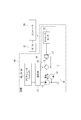
- the monitor 31 displays various data such as the engine coolant temperature, the remaining fuel amount, and the hydraulic oil temperature detected by a sensor and the like, and includes a processing unit 31A, a memory 31B, and a display unit 31C.
- the processing unit 31A includes a data storage unit 310, a state estimation unit 311, a life prediction unit 312, a replacement presence / absence determination unit 313, and an alarm notification unit 314 having the same functions as those of the first embodiment. Further, a state estimation table is stored and stored in the memory 31B, as in the first embodiment.
- the state estimation unit 311 estimates the clogged state of the filter element 15 based on the temperature detection result detected by the temperature sensor 19 with reference to the table stored in the memory 31B. In addition, the state estimation unit 311 generates image information indicating how much the clogging state of the filter element 15 is, for example, image information that displays high, medium, and low, and displays it on the display unit 31C. Display. The image information to be displayed is not limited to this, and may be an image that displays the degree of clogging as a percentage. As in the first embodiment, the data storage unit 310 stores the maximum oil temperature data of the valve 17 in time series, and outputs the result to the life prediction unit 312 and the replacement presence / absence determination unit 313.
- the life prediction unit 312 predicts the life of the filter element 15 based on the maximum oil temperature in the opened state of the valve 17 from the maximum oil temperature monitoring result of the state estimation unit 311.
- the method is the same as in the first embodiment.
- the replacement presence / absence determination unit 313 determines that the filter element 15 has been replaced based on the state estimation of the filter element 15 by the state estimation unit 311.
- the alarm notification unit 314 issues a clogging alarm on the display unit 31C.
- the clogging state may be notified not only by displaying on the display unit 31C but also by an alarm sound.
- the same operations and effects as those of the first embodiment can be enjoyed.
- the filter element 15 since the state of the filter element 15 is estimated by the monitor 31 in the hydraulic excavator 1, the filter element 15 can be managed in a stand-alone manner, resulting in a complicated system. There is nothing.
- the temperature sensor 19 was provided in the suction inlet vicinity of the hydraulic pump 12, this invention is not limited to this.
- the temperature sensor may be provided inside the hydraulic oil tank 11 or may be provided in the vicinity of the lower hole 142 of the filter element 15.
- the stroke sensor 18 is used to detect the opening / closing of the valve 17.
- the present invention is not limited to this, and an optical sensor such as an encoder may be used.
- the specific structure, shape, and the like when implementing the present invention may be other structures as long as the object of the present invention can be achieved.
- SYMBOLS 1 Hydraulic excavator, 2 ... Lower traveling body, 2A ... Traveling device, 2B ... Track, 3 ... Upper turning body, 3A ... Counterweight, 4 ... Cab, 5 ... Working machine, 6 ... Boom, 6A ... Boom cylinder, 7 ... Arm, 7A ... Arm cylinder, 8 ... Bucket, 8A ... Bucket cylinder, 10 ... Hydraulic circuit, 11 ... Hydraulic oil tank, 12 ... Hydraulic pump, 13 ... Operation valve, 14 ... Oil filter device, 14A ... Case body, 14B ... Lid, 14C ... Coil spring, 14D ... Plate, 15 ... Filter element, 15A ...
- position information acquisition unit 204 ... operation information acquisition unit 240 ... data storage unit 241 ... state estimation unit 242 ... life prediction unit, 243 ... replacement presence / absence determination unit, 310 ... data storage unit, 311 ... state estimation unit, 312 ... life prediction unit, 313 ... replacement presence / absence determination unit, 314 ... alarm reporting unit.
Landscapes
- Engineering & Computer Science (AREA)
- Chemical & Material Sciences (AREA)
- Chemical Kinetics & Catalysis (AREA)
- General Engineering & Computer Science (AREA)
- Structural Engineering (AREA)
- Civil Engineering (AREA)
- Mining & Mineral Resources (AREA)
- Analytical Chemistry (AREA)
- Physics & Mathematics (AREA)
- Fluid Mechanics (AREA)
- Mechanical Engineering (AREA)
- Fluid-Pressure Circuits (AREA)
- Filtration Of Liquid (AREA)
- Component Parts Of Construction Machinery (AREA)
- Indication Of The Valve Opening Or Closing Status (AREA)
Abstract
Description
オイルフィルタ装置は、フィルタケース内にフィルタエレメントが収容され、フィルタケースの吸込口から流入した油は、排出口から排出されるまでに、フィルタエレメントの濾材を通過し、油に含まれた異物が除去される。
図1には、本発明の実施形態に係る油圧ショベル1が示され、建設機械としての油圧ショベル1は、下部走行体2と、上部旋回体3と、作業機5とを備えている。
下部走行体2は、図示を略したが、トラックフレームと、トラックフレームの走行方向に直交する車幅方向両端に設けられる一対の走行装置2Aとを備えている。走行装置2Aは、トラックフレームに設けられた駆動輪および遊動輪に巻回される履帯2Bを備え、駆動輪を駆動させることにより、履帯2Bの延出方向に油圧ショベル1を前後進させる。
上部旋回体3の走行方向前部左側には、キャブ4が設けられ、このキャブ4に隣接した前部中央には、作業機5が設けられている。上部旋回体3のキャブ4および作業機5とは反対側の後部には、カウンタウェイト3Aが設けられている。カウンタウェイト3Aは、油圧ショベル1の掘削作業時の重量バランスをとるために設けられている。
キャブ4は、内部にオペレータが乗車して油圧ショベル1を操縦する。キャブ4内には、図1では図示を略したが、オペレータシートが設けられ、オペレータシートの両脇には、操作レバーが設けられている。また、キャブ4の床面には、走行ペダルが設けられている。
ブーム6は、基端が上部旋回体3に動作可能に接続される。ブーム6は、上部旋回体3およびブーム6にそれぞれの先端が接続されるブームシリンダ6Aを伸縮させることにより、上下に動作される。
アーム7は、ブーム6の先端にアーム7の基端がブーム6に動作可能に接続される。アーム7は、ブーム6およびアーム7にそれぞれの先端が接続されるアームシリンダ7Aを伸縮させることにより、上下に動作される。
ブームシリンダ6A、アームシリンダ7A、およびバケットシリンダ8Aは、油圧ポンプ12(図2参照)から吐出される作動油によって駆動する油圧シリンダである。
図2には、本実施形態の油圧ショベル1に設けられる油圧回路10が示されている。油圧回路10は、作動油タンク11、油圧ポンプ12、操作弁13、およびオイルフィルタ装置14を備える。
作動油タンク11は、油圧ポンプ12に作動油を供給するとともに、油圧シリンダ6A、7A、8Aを駆動した戻り作動油を貯留する。油圧ポンプ12は、作動油タンク11から作動油を吸い込み、操作弁13に作動油を圧送する。
操作弁13は、図示しないキャブ4内の操作レバーの操作により、スプールの位置が変更され、アクチュエータである油圧シリンダ6A、7A、8Aに作動油を供給し、油圧シリンダ6A、7A、8Aを伸長させたり、縮退させたりすることにより、ブーム6、アーム7、およびバケット8を動作させる。なお、操作弁13からの作動油は、油圧ショベル1を駆動する油圧モータに供給されてもよい。そして、油圧モータから排出された作動油は、操作弁13を経由して作動油タンク11に戻る。
また、操作弁13は、油圧シリンダ6A、7A、8Aからの戻りの作動油を、オイルフィルタ装置14経由で作動油タンク11に戻すためにも操作される。
バルブ17には、開度センサとしてのストロークセンサ18が設けられ、ストロークセンサ18による検出値は、コントローラ20に出力される。
また、油圧ポンプ12の吸込口には、温度センサ19が設けられ、温度センサ19による検出値は、コントローラ20に出力される。
モニタ21は、処理部および表示部を備え、表示部には、たとえば、センサ等で検出されたエンジンの冷却水の温度、燃料残量、作動油の温度等の各種データが表示される。
通信端末22は、センサ等で検出された検出値や、モニタ21で設定された設定値、Global Positioning System(GPS)23で検出された油圧ショベル1の位置等の情報を外部に出力する。本実施形態では、通信端末22は、衛星通信回線や、携帯通信網を介して、サーバ24にこれらの情報を出力している。
図3には、オイルフィルタ装置14の詳細構造が示されている。オイルフィルタ装置14は、ケース本体14Aおよび蓋体14Bを備える。ケース本体14Aは、円筒状の容器として構成され、内部にフィルタエレメント15が収容される。
ケース本体14Aの側面には、吸込部としての戻り油吸込口141が形成され、操作弁13からの戻り配管が接続され、操作弁13から戻ってきた作動油が、ケース本体14A内に供給される。
ケース本体14Aの底部には、中央に排出部としての孔142が形成され、フィルタエレメント15によって異物が除去された作動油が、作動油タンク11内に供給される。
コイルスプリング14Cは、プレート14Dを介してフィルタエレメント15を下方に付勢し、フィルタエレメント15をケース本体14A内に固定する。
バルブ17は、バルブステム17Bと、バルブ本体17Cと、コイルスプリング17Dとを備え、バイパス流路16を流れる油の流量を調整する。
バルブステム17Bは、鋼製軸状部材から構成され、バルブボディ17Aの内部に収容され、バルブボディ17Aに対して、上下方向に摺動自在に支持される。
可動部18Aは、バルブステム17Bの基端に接続され、バルブステム17Bの摺動とともに、上下に摺動する。
磁石18Bは、可動部18Aの上端に設けられ、可動部18Aの上下の摺動とともに、上下に移動する。
センサ本体18Cは、内部に磁気感応素子、たとえばホールICが設けられ、磁石18Bの上下の移動による磁場の変化を検出する。
しかしながら、フィルタエレメント15の濾材15Aが異物を捕捉して、目詰まりしてくると、濾材15Aを通過しにくくなり、吸い込まれた作動油は、バイパス流路16に供給され、バイパス流路16の内の作動油の圧力が高くなっていく。
バルブステム17Bが下方に摺動すると、同時にストロークセンサ18の可動部18Aも下方に摺動する。ストロークセンサ18のセンサ本体18Cは、これを検出して電気信号を出力して、コントローラ20にバルブ17が開状態であることを報せる。
図4には、コントローラ20およびサーバ24の機能ブロック図が示されている。
コントローラ20は、油圧ショベル1内に設けられた種々のセンサの検出データを取得する。コントローラ20は、作動油温取得部201、バルブ開閉状態取得部202、位置情報取得部203、および稼働情報取得部204を備える。
バルブ開閉状態取得部202は、ストロークセンサ18によるバルブ17の開閉状態の検出データを取得して、バルブ17の開閉を検知する。具体的には、バルブ開閉状態取得部202は、ストロークセンサ18で検出されたストロークの量が所定の閾値を超えている時間が、所定時間継続しているか否かに基づいて、バルブ17が開状態であることを取得する。
位置情報取得部203は、GPS23で検出された油圧ショベル1の現在位置を取得する。
コントローラ20は、取得した作動油の温度、バルブ17の開閉状態、および油圧ショベル1の稼働情報を、通信端末22に出力する。
メモリ24Aは、後述する各種のテーブルデータを記憶する。
寿命予測部242は、状態推定部241の最高油温のモニタ結果から、バルブ17の開状態におけるフィルタエレメント15の状態の推移に基づいて、フィルタエレメント15の寿命を予測する。
たとえば、図7Aの時刻t1におけるフィルタエレメント15の寿命は、時刻t1および時刻t1近傍の時刻t0における最高油温の変化量から、目詰まり警報発報油温に達する時刻t2を外挿などにより計算し、時刻t1から時刻t2までの時間T_remainをフィルタエレメント15の寿命として推定する。
また、図7Bに示すように、寿命予測部242は、時刻t4の場合のように、バルブ17の開状態における最高油温に急激な変化が生じた場合、フィルタエレメント15に異常が生じたと判定する。
たとえば、図6の場合、時刻t3、時刻t5を、フィルタエレメント15を交換した時期であると判定する。なお、フィルタエレメント15の交換により、所定の稼働時間(たとえば1000時間)が経過すると、フィルタエレメント15の交換を促すメッセージをモニタ21等に表示する。また、モニタ21等には、過去の履歴として交換した時期も表示される。
次に、前述したコントローラ20におけるバルブ17の開状態の判定方法を、図8および図9に示されるフローチャートに基づいて説明する。なお、コントローラ20は、このフローチャートに示した一連の処理を、所定周期、たとえば、0.01秒周期で繰り返し実行する。なお、油圧ショベル1による作業機5の稼働状態や、稼働負荷の変化があっても、フィルタエレメント15に流入する作動油量は、一定の時間内では平均化され、作業機5の稼働による変動は無視することができる。
また、本実施形態では、エンジンの始動をトリガーとして最高油温の計測を行っているが、たとえば、何らかの他の原因でバルブ17が開状態であると判断されたことをトリガーとして、最高油温の計測を行ってもよい。
初期化されている場合(S1:Yes)、手順S3に進む。
初期化されていない場合(S1:No)、作動油温取得部201は、バルブ17の開状態における最高油温T_maxを、たとえば-100℃に初期化し、バルブ開閉状態取得部202は、バルブ開状態継続時間OpenTimeを0秒に初期化するとともに、バルブストローク閉位置L_0を0mmに初期化する(手順S2)。
処理開始判定時間を超えていない場合(S3:No)、処理を終了する。
処理開始判定時間を超えている場合(S3:Yes)、バルブ開閉状態取得部202は、ストロークセンサ18により、バルブ17のストロークLを計測する(手順S4)。
バルブ開閉状態取得部202は、操作レバーが中立状態にあるか否かを判定する(手順S5)。
操作レバーが中立状態でない場合(S5:No)、手順S7に進む。
操作レバーが中立状態である場合(S5:Yes)、バルブ開閉状態取得部202は、バルブストローク閉位置L_0を、現在のストロークセンサ18で計測されたストロークLに自動補正する(手順S6)。
開判定ストロークよりも小さいと判定されたら(S7:No)、バルブ開閉状態取得部202は、バルブ17の開状態継続時間OpenTimeを0にリセットし(手順S8)、処理を終了する。
開判定ストロークよりも大きいと判定されたら(S7:Yes)、バルブ開閉状態取得部202は、バルブ17の開状態継続時間OpenTimeに演算周期(たとえば0.01秒)を加え、バルブ17の開状態継続時間OpenTimeの更新を行う(手順S9)。
バルブ17の開状態継続時間OpenTimeが、開状態の判定時間を超えていない場合(S10:No)、処理を終了する。
バルブ17の開状態継続時間OpenTimeが、開状態の判定時間を超えている場合(S10:Yes)、作動油温取得部201は、温度センサ19により、作動油温度Tを計測する(手順S11)。
計測された作動油温度Tが、最高油温T_max以下の場合(S12:No)、手順S14に進む。
計測された作動油温度Tが、最高油温T_maxを超えている場合(S12:Yes)、作動油温取得部201は、最高油温T_maxを計測された作動油温度Tに更新する(手順S13)。
計測された作動油温度Tが警報発報油温以下の場合、手順S16に進む。
計測された作動油温度Tが警報発報油温を超えている場合、作動油温取得部201は、モニタ21にその旨を出力し、モニタ21は、フィルタエレメント15が目詰まりしていることを示す目詰まり警報を発報する(手順S15)
送信出力のタイミングではないと判定された場合(手順S16:No)、処理を終了する。
コントローラ20は、バルブ開閉状態取得部202および作動油温取得部201を備えていることにより、ストロークセンサ18でバイパス流路16におけるバルブ17が開状態であると検出されたときに、温度センサ19で作動油の温度を検出できる。したがって、サーバ24でバルブ17の開状態の最高油温の推移を解析することにより、フィルタエレメント15の目詰まり状態を推定し、フィルタエレメント15の寿命予測や、交換有無の判定を行うことができる。
次に、本発明の第2実施形態について説明する。なお、以下の説明では、すでに説明した部分と同一の部分については、同一符号を付して説明を省略する。
前述の第1実施形態では、センサ等で検出されたバルブ17の開閉状態の検出結果、温度センサ19による温度検出結果を、通信端末22を介して、サーバ24に出力していた。
これに対して、本実施形態では、図10および図11に示すように、センサ等で検出されたバルブ17の開閉状態の検出、温度センサ19による温度検出結果を、モニタ31で処理している点が相違する。
処理部31Aは、第1実施形態と同様の機能を有する、データ蓄積部310、状態推定部311と、寿命予測部312、交換有無判定部313と、警報発報部314とを備える。また、メモリ31B内には、第1実施形態と同様に、状態推定テーブルが記憶保存されている。
また、状態推定部311は、フィルタエレメント15の目詰まりの状態が、どの程度の度合いであるかの画像情報、たとえば、高、中、低を表示する画像情報を生成し、表示部31C上に表示させる。なお、表示させる画像情報は、これに限らず、目詰まりの度合いをパーセント表示させるような画像であってもよい。
データ蓄積部310は、第1実施形態と同様に、バルブ17の最高油温データを、時系列で蓄積し、その結果を寿命予測部312および交換有無判定部313に出力する。
交換有無判定部313は、状態推定部311によるフィルタエレメント15の状態推定に基づいて、フィルタエレメント15が交換されたことを判定する。
警報発報部314は、温度センサ19で検出された作動油の温度が警報発報油温を超えている場合、表示部31C上に目詰まり警報を発報させる。なお、目詰まり状態は、表示部31C上に表示させるだけでなく、発報音によって知らせてもよい。
また、本実施形態によれば、油圧ショベル1内のモニタ31でフィルタエレメント15の状態を推定しているため、スタンドアロンでフィルタエレメント15の目詰まり管理を行うことができ、システムの複雑化を招くこともない。
なお、本発明は前述の実施形態に限定されるものではなく、本発明の目的を達成できる範囲での変形、改良等は本発明に含まれるものである。
前記実施形態では、油圧ショベル1にフィルタ状態推定システムを採用していたが、これに限らず、他のホイールローダ、ブルドーザ等の他の建設機械に採用してもよい。
前記実施形態では、バルブ17の開閉を検知するものとして、ストロークセンサ18を用いていたが、これに限らず、エンコーダ等の光学式のセンサを用いてもよい。
その他、本発明の実施の際の具体的な構造および形状等は、本発明の目的を達成できる範囲で他の構造等としてもよい。
Claims (4)
- 油圧回路中に設けられるフィルタの状態を推定するフィルタ状態推定システムであって、
前記油圧回路は、
フィルタと、
前記フィルタを迂回して油が流れるバイパス流路と、
前記バイパス流路中に設けられ、差圧に基づいて開閉するバルブとを備え、
前記バルブの開閉を検出するセンサと、
油の温度を検出する温度センサと、
前記センサおよび前記温度センサにより検出された検出結果に基づいて、前記フィルタの状態を推定する状態推定部と、を備え、
前記状態推定部は、前記センサにより前記バルブが開状態であると検知されたときの前記温度センサにより検出された油の温度に基づいて、前記フィルタの状態を推定することを特徴とするフィルタ状態推定システム。 - 請求項1に記載のフィルタ状態推定システムにおいて、
前記状態推定部は、前記バルブが開状態における油の温度を一定時間モニタし、
前記状態推定部により推定されたフィルタの状態の推移に基づいて、前記フィルタの寿命を予測する寿命予測部を備えていることを特徴とするフィルタ状態推定システム。 - 請求項1または請求項2に記載のフィルタ状態推定システムにおいて、
前記状態推定部は、前記バルブが開状態における油の温度を一定時間モニタし、
前記状態推定部により推定されたフィルタの状態の推移に基づいて、前記フィルタが交換されたことを判定する交換有無判定部を備えていることを特徴とするフィルタ状態推定システム。 - 油圧回路中に設けられるフィルタの状態を推定するフィルタ状態の推定方法であって、
前記油圧回路は、
フィルタと、
前記フィルタを迂回して油が流れるバイパス流路と、
前記バイパス流路中に設けられ、差圧に基づいて開閉するバルブとを備え、
前記バルブが開状態であると検知する手順と、
前記バルブが開状態であると検知されたときの油の温度に基づいて、前記フィルタの状態を推定する手順と、
を実施することを特徴とするフィルタ状態の推定方法。
Priority Applications (5)
| Application Number | Priority Date | Filing Date | Title |
|---|---|---|---|
| CN201780001602.0A CN107660259B (zh) | 2017-06-16 | 2017-06-16 | 过滤器状态推定系统及过滤器状态的推定方法 |
| US15/577,942 US10695699B2 (en) | 2017-06-16 | 2017-06-16 | Filter state estimation system and filter state estimation method |
| DE112017000028.9T DE112017000028B4 (de) | 2017-06-16 | 2017-06-16 | System zur schätzung des zustands eines filters und verfahren zur schätzung des zustands eines filters |
| PCT/JP2017/022363 WO2017191852A1 (ja) | 2017-06-16 | 2017-06-16 | フィルタ状態推定システムおよびフィルタ状態の推定方法 |
| JP2017550788A JP6311080B1 (ja) | 2017-06-16 | 2017-06-16 | フィルタ状態推定システムおよびフィルタ状態の推定方法 |
Applications Claiming Priority (1)
| Application Number | Priority Date | Filing Date | Title |
|---|---|---|---|
| PCT/JP2017/022363 WO2017191852A1 (ja) | 2017-06-16 | 2017-06-16 | フィルタ状態推定システムおよびフィルタ状態の推定方法 |
Publications (1)
| Publication Number | Publication Date |
|---|---|
| WO2017191852A1 true WO2017191852A1 (ja) | 2017-11-09 |
Family
ID=60203707
Family Applications (1)
| Application Number | Title | Priority Date | Filing Date |
|---|---|---|---|
| PCT/JP2017/022363 Ceased WO2017191852A1 (ja) | 2017-06-16 | 2017-06-16 | フィルタ状態推定システムおよびフィルタ状態の推定方法 |
Country Status (5)
| Country | Link |
|---|---|
| US (1) | US10695699B2 (ja) |
| JP (1) | JP6311080B1 (ja) |
| CN (1) | CN107660259B (ja) |
| DE (1) | DE112017000028B4 (ja) |
| WO (1) | WO2017191852A1 (ja) |
Cited By (6)
| Publication number | Priority date | Publication date | Assignee | Title |
|---|---|---|---|---|
| WO2019181769A1 (ja) * | 2018-03-19 | 2019-09-26 | いすゞ自動車株式会社 | 検出装置 |
| JP2021156077A (ja) * | 2020-03-30 | 2021-10-07 | 住友重機械工業株式会社 | ショベル及びショベルの管理装置 |
| JPWO2020171018A1 (ja) * | 2019-02-19 | 2021-12-16 | 株式会社フジキン | バルブ |
| CN114876916A (zh) * | 2022-04-28 | 2022-08-09 | 索特传动设备有限公司 | 回油过滤器及工程机械 |
| WO2023176496A1 (ja) * | 2022-03-15 | 2023-09-21 | 株式会社小松製作所 | オイルフィルタ装置 |
| WO2023176497A1 (ja) * | 2022-03-15 | 2023-09-21 | 株式会社小松製作所 | オイルフィルタ装置 |
Families Citing this family (9)
| Publication number | Priority date | Publication date | Assignee | Title |
|---|---|---|---|---|
| DE102018214923A1 (de) * | 2018-09-03 | 2020-03-05 | Rolls-Royce Deutschland Ltd & Co Kg | Überwachung von Servoventil-Filterelementen |
| CN109595743B (zh) * | 2018-10-16 | 2022-03-04 | 珠海格力电器股份有限公司 | 一种过滤网清洗提醒方法、装置及设备 |
| JP7198070B2 (ja) * | 2018-12-11 | 2022-12-28 | ヤマシンフィルタ株式会社 | フィルタ寿命予測装置 |
| DE102019106977B4 (de) * | 2019-03-19 | 2024-04-04 | Argo-Hytos Group Ag | Anordnung mit einer Filtereinrichtung und einem Trägerelement und Verfahren zur Erkennung eines Filterelements |
| DE102020200388A1 (de) | 2020-01-14 | 2021-07-15 | Zf Friedrichshafen Ag | Vorrichtung und Verfahren zum Ermitteln des Beladezustands eines Filters |
| DE102020204488B4 (de) | 2020-04-07 | 2023-11-02 | Zf Friedrichshafen Ag | Verfahren und Auswertesystem zum Bestimmen eines Filterverschmutzungszustands, sowie Filtersystem und Maschine |
| CN111425488A (zh) * | 2020-05-13 | 2020-07-17 | 三一重机有限公司 | 液压油温度控制系统和挖掘机 |
| JP7400791B2 (ja) * | 2021-10-19 | 2023-12-19 | コベルコ建機株式会社 | 目詰まり判定システム、目詰まり判定方法、および目詰まり判定プログラム |
| SE548252C2 (en) * | 2024-04-22 | 2026-05-04 | Husqvarna Ab | A demolition robot with a hydraulic system monitoring function |
Citations (2)
| Publication number | Priority date | Publication date | Assignee | Title |
|---|---|---|---|---|
| JPH0651508U (ja) * | 1991-11-18 | 1994-07-15 | 株式会社新潟鉄工所 | フィルタの目詰り警報装置 |
| JP2013000608A (ja) * | 2011-06-10 | 2013-01-07 | Komatsu Ltd | オイルフィルタ装置 |
Family Cites Families (20)
| Publication number | Priority date | Publication date | Assignee | Title |
|---|---|---|---|---|
| JPS4895026A (ja) | 1972-03-17 | 1973-12-06 | ||
| JPS5019081B2 (ja) | 1972-05-26 | 1975-07-04 | ||
| JPS602526B2 (ja) * | 1979-06-15 | 1985-01-22 | 株式会社クボタ | 作業車の安全装置 |
| JPS5910402A (ja) | 1982-07-10 | 1984-01-19 | Toshiba Corp | 圧延機及び圧延方法 |
| JPS602526A (ja) | 1983-05-23 | 1985-01-08 | Chuo Kakoki Kk | ダイヤフラムポンプによる粉体の搬送方法 |
| DE4011913A1 (de) * | 1990-04-12 | 1991-10-17 | Beyer Rudi Dipl Ing | Hydrauliksystem mit filter und filteranordnung |
| US5275909A (en) | 1992-06-01 | 1994-01-04 | Ocg Microelectronic Materials, Inc. | Positive-working radiation sensitive mixtures and articles containing alkali-soluble binder, o-quinonediazide photoactive compound and BLANKOPHOR FBW acting dye |
| JPH0734491A (ja) * | 1993-07-20 | 1995-02-03 | Hitachi Constr Mach Co Ltd | 建設機械のフィルタ目詰り検出装置 |
| JP3499303B2 (ja) | 1994-10-07 | 2004-02-23 | 山信工業株式会社 | 差圧インジケータ付き濾過装置 |
| DE29705018U1 (de) * | 1996-06-26 | 1997-05-15 | Hydac Technology Gmbh, 66280 Sulzbach | Thermo-Bypass-Ventil |
| JP2001038114A (ja) | 1999-08-02 | 2001-02-13 | Saginomiya Seisakusho Inc | 油圧用フィルタ監視システム及び油圧用フィルタ監視方法 |
| DE10357217B4 (de) | 2003-12-08 | 2005-12-29 | Sauer-Danfoss (Neumünster) GmbH & Co OHG | Anordnung zur Filterung von Hydraulikflüssigkeit |
| ITRE20050036A1 (it) * | 2005-04-06 | 2006-10-07 | Ufi Filters Spa | Filtro per gasolio perfezionato |
| US7174273B2 (en) * | 2005-05-11 | 2007-02-06 | Hamilton Sundstrand Corporation | Filter monitoring system |
| DE102007037525A1 (de) | 2007-08-09 | 2009-02-12 | Joma-Polytec Kunststofftechnik Gmbh | Ölfiltersystem und Verfahren zum Betreiben eines Ölfiltersystems |
| BRPI0722165A2 (pt) * | 2007-10-19 | 2014-03-18 | Mp Filtri S P A | Dispositivo para filtração de óleo pressurizado |
| JP2011085215A (ja) * | 2009-10-16 | 2011-04-28 | Caterpillar Sarl | 作業用車両の作動油タンク |
| JP2011190738A (ja) * | 2010-03-15 | 2011-09-29 | Iseki & Co Ltd | コンバインのディーゼルパティキュレートフィルタ再生制御装置 |
| DE102012017059A1 (de) | 2012-08-29 | 2014-03-06 | Robert Bosch Gmbh | Filteranordnung zur Ölfiltration und Verfahren zum Betreiben derselben |
| CN205047584U (zh) * | 2015-06-30 | 2016-02-24 | 常州福宇精密模具有限公司 | 航空液压油净化装置 |
-
2017
- 2017-06-16 US US15/577,942 patent/US10695699B2/en active Active
- 2017-06-16 CN CN201780001602.0A patent/CN107660259B/zh active Active
- 2017-06-16 WO PCT/JP2017/022363 patent/WO2017191852A1/ja not_active Ceased
- 2017-06-16 JP JP2017550788A patent/JP6311080B1/ja active Active
- 2017-06-16 DE DE112017000028.9T patent/DE112017000028B4/de active Active
Patent Citations (2)
| Publication number | Priority date | Publication date | Assignee | Title |
|---|---|---|---|---|
| JPH0651508U (ja) * | 1991-11-18 | 1994-07-15 | 株式会社新潟鉄工所 | フィルタの目詰り警報装置 |
| JP2013000608A (ja) * | 2011-06-10 | 2013-01-07 | Komatsu Ltd | オイルフィルタ装置 |
Cited By (15)
| Publication number | Priority date | Publication date | Assignee | Title |
|---|---|---|---|---|
| WO2019181769A1 (ja) * | 2018-03-19 | 2019-09-26 | いすゞ自動車株式会社 | 検出装置 |
| JPWO2020171018A1 (ja) * | 2019-02-19 | 2021-12-16 | 株式会社フジキン | バルブ |
| JP7374513B2 (ja) | 2019-02-19 | 2023-11-07 | 株式会社フジキン | バルブ |
| JP2021156077A (ja) * | 2020-03-30 | 2021-10-07 | 住友重機械工業株式会社 | ショベル及びショベルの管理装置 |
| JP7455632B2 (ja) | 2020-03-30 | 2024-03-26 | 住友重機械工業株式会社 | ショベル及びショベルの管理装置 |
| JP2023135358A (ja) * | 2022-03-15 | 2023-09-28 | 株式会社小松製作所 | オイルフィルタ装置 |
| WO2023176497A1 (ja) * | 2022-03-15 | 2023-09-21 | 株式会社小松製作所 | オイルフィルタ装置 |
| JP2023135359A (ja) * | 2022-03-15 | 2023-09-28 | 株式会社小松製作所 | オイルフィルタ装置 |
| WO2023176496A1 (ja) * | 2022-03-15 | 2023-09-21 | 株式会社小松製作所 | オイルフィルタ装置 |
| DE112023000414T5 (de) | 2022-03-15 | 2024-09-26 | Komatsu Ltd. | Ölfiltervorrichtung |
| DE112023000446T5 (de) | 2022-03-15 | 2024-11-21 | Komatsu Ltd. | Ölfiltervorrichtung |
| JP7767191B2 (ja) | 2022-03-15 | 2025-11-11 | 株式会社小松製作所 | オイルフィルタ装置 |
| JP7767190B2 (ja) | 2022-03-15 | 2025-11-11 | 株式会社小松製作所 | オイルフィルタ装置 |
| US12539474B2 (en) | 2022-03-15 | 2026-02-03 | Komatsu Ltd. | Oil filter device |
| CN114876916A (zh) * | 2022-04-28 | 2022-08-09 | 索特传动设备有限公司 | 回油过滤器及工程机械 |
Also Published As
| Publication number | Publication date |
|---|---|
| JP6311080B1 (ja) | 2018-04-11 |
| US20180361283A1 (en) | 2018-12-20 |
| DE112017000028T5 (de) | 2018-01-11 |
| CN107660259A (zh) | 2018-02-02 |
| JPWO2017191852A1 (ja) | 2018-05-17 |
| CN107660259B (zh) | 2022-03-29 |
| DE112017000028B4 (de) | 2019-07-18 |
| US10695699B2 (en) | 2020-06-30 |
Similar Documents
| Publication | Publication Date | Title |
|---|---|---|
| JP6311080B1 (ja) | フィルタ状態推定システムおよびフィルタ状態の推定方法 | |
| US11401695B2 (en) | Work machine | |
| KR101775730B1 (ko) | 건설 기계의 유압 구동 장치 | |
| US9145657B2 (en) | System for controlling land leveling work which uses an excavator | |
| US8880302B1 (en) | Working vehicle and method for controlling the working vehicle | |
| AU2008312088A1 (en) | Method and arrangement for detecting leakage of hydraulic oil | |
| JP5402875B2 (ja) | 建設機械のフィルタ目詰まり検出装置 | |
| US8775035B2 (en) | Hydraulic management system and method based on auxiliary work tool usage | |
| JP7001573B2 (ja) | 建設機械 | |
| JP2020143591A (ja) | 油圧ポンプの故障診断装置、故障診断装置を備える建設機械、故障診断方法および故障診断プログラム | |
| CN104053842B (zh) | 作业机械 | |
| JP2010174574A (ja) | 作業機械 | |
| WO2020027135A1 (ja) | 作業機械 | |
| KR102294964B1 (ko) | 밸브체 상태 감시 장치 및 유체압 구동 장치 | |
| KR20230147171A (ko) | 작업 기계 | |
| JP4286649B2 (ja) | 建設機械のエンジン冷却水系統故障診断装置 | |
| JP7400791B2 (ja) | 目詰まり判定システム、目詰まり判定方法、および目詰まり判定プログラム | |
| JP2006104836A (ja) | 建設機械の動作機能監視装置 | |
| JP4178101B2 (ja) | 建設機械の作動油冷却系統故障診断装置 | |
| JP2008232244A (ja) | フィルタ圧力制御機構をそなえた油圧駆動装置 | |
| JP6002064B2 (ja) | 油圧ショベルの油圧制御装置 | |
| JP2001221793A (ja) | 作動油の汚れ状態診断装置 | |
| JP2009036252A (ja) | 目詰まり検出装置およびこれを備えた作業車両 | |
| CN103133459B (zh) | 液压系统的溢流预警方法、溢流预警装置和工程机械 | |
| KR102757088B1 (ko) | 오일필터 예지보전 시스템 |
Legal Events
| Date | Code | Title | Description |
|---|---|---|---|
| ENP | Entry into the national phase |
Ref document number: 2017550788 Country of ref document: JP Kind code of ref document: A |
|
| WWE | Wipo information: entry into national phase |
Ref document number: 112017000028 Country of ref document: DE |
|
| 121 | Ep: the epo has been informed by wipo that ep was designated in this application |
Ref document number: 17792784 Country of ref document: EP Kind code of ref document: A1 |
|
| 122 | Ep: pct application non-entry in european phase |
Ref document number: 17792784 Country of ref document: EP Kind code of ref document: A1 |