US10695699B2 - Filter state estimation system and filter state estimation method - Google Patents
Filter state estimation system and filter state estimation method Download PDFInfo
- Publication number
- US10695699B2 US10695699B2 US15/577,942 US201715577942A US10695699B2 US 10695699 B2 US10695699 B2 US 10695699B2 US 201715577942 A US201715577942 A US 201715577942A US 10695699 B2 US10695699 B2 US 10695699B2
- Authority
- US
- United States
- Prior art keywords
- filter
- state
- valve
- temperature
- oil
- Prior art date
- Legal status (The legal status is an assumption and is not a legal conclusion. Google has not performed a legal analysis and makes no representation as to the accuracy of the status listed.)
- Active, expires
Links
- 238000000034 method Methods 0.000 title claims description 17
- 238000001514 detection method Methods 0.000 claims abstract description 16
- 230000007704 transition Effects 0.000 claims description 4
- 239000003921 oil Substances 0.000 description 70
- 239000010720 hydraulic oil Substances 0.000 description 69
- 238000004891 communication Methods 0.000 description 15
- 238000001914 filtration Methods 0.000 description 9
- 238000013500 data storage Methods 0.000 description 8
- 239000000126 substance Substances 0.000 description 8
- 238000010276 construction Methods 0.000 description 6
- 238000012545 processing Methods 0.000 description 5
- 230000008859 change Effects 0.000 description 4
- 239000000446 fuel Substances 0.000 description 4
- 230000004048 modification Effects 0.000 description 4
- 238000012986 modification Methods 0.000 description 4
- 239000000498 cooling water Substances 0.000 description 3
- 238000010586 diagram Methods 0.000 description 3
- 230000007935 neutral effect Effects 0.000 description 3
- 238000011144 upstream manufacturing Methods 0.000 description 3
- 230000005856 abnormality Effects 0.000 description 2
- 230000006870 function Effects 0.000 description 2
- 238000005259 measurement Methods 0.000 description 2
- 230000001960 triggered effect Effects 0.000 description 2
- 238000004364 calculation method Methods 0.000 description 1
- 230000000694 effects Effects 0.000 description 1
- 230000003287 optical effect Effects 0.000 description 1
- 230000008569 process Effects 0.000 description 1
- 230000004044 response Effects 0.000 description 1
Images


Classifications
-
- B—PERFORMING OPERATIONS; TRANSPORTING
- B01—PHYSICAL OR CHEMICAL PROCESSES OR APPARATUS IN GENERAL
- B01D—SEPARATION
- B01D35/00—Filtering devices having features not specifically covered by groups B01D24/00 - B01D33/00, or for applications not specifically covered by groups B01D24/00 - B01D33/00; Auxiliary devices for filtration; Filter housing constructions
- B01D35/14—Safety devices specially adapted for filtration; Devices for indicating clogging
- B01D35/143—Filter condition indicators
-
- B—PERFORMING OPERATIONS; TRANSPORTING
- B01—PHYSICAL OR CHEMICAL PROCESSES OR APPARATUS IN GENERAL
- B01D—SEPARATION
- B01D29/00—Filters with filtering elements stationary during filtration, e.g. pressure or suction filters, not covered by groups B01D24/00 - B01D27/00; Filtering elements therefor
- B01D29/11—Filters with filtering elements stationary during filtration, e.g. pressure or suction filters, not covered by groups B01D24/00 - B01D27/00; Filtering elements therefor with bag, cage, hose, tube, sleeve or like filtering elements
- B01D29/114—Filters with filtering elements stationary during filtration, e.g. pressure or suction filters, not covered by groups B01D24/00 - B01D27/00; Filtering elements therefor with bag, cage, hose, tube, sleeve or like filtering elements arranged for inward flow filtration
-
- B—PERFORMING OPERATIONS; TRANSPORTING
- B01—PHYSICAL OR CHEMICAL PROCESSES OR APPARATUS IN GENERAL
- B01D—SEPARATION
- B01D29/00—Filters with filtering elements stationary during filtration, e.g. pressure or suction filters, not covered by groups B01D24/00 - B01D27/00; Filtering elements therefor
- B01D29/60—Filters with filtering elements stationary during filtration, e.g. pressure or suction filters, not covered by groups B01D24/00 - B01D27/00; Filtering elements therefor integrally combined with devices for controlling the filtration
- B01D29/608—Filters with filtering elements stationary during filtration, e.g. pressure or suction filters, not covered by groups B01D24/00 - B01D27/00; Filtering elements therefor integrally combined with devices for controlling the filtration by temperature measuring
-
- B—PERFORMING OPERATIONS; TRANSPORTING
- B01—PHYSICAL OR CHEMICAL PROCESSES OR APPARATUS IN GENERAL
- B01D—SEPARATION
- B01D35/00—Filtering devices having features not specifically covered by groups B01D24/00 - B01D33/00, or for applications not specifically covered by groups B01D24/00 - B01D33/00; Auxiliary devices for filtration; Filter housing constructions
- B01D35/02—Filters adapted for location in special places, e.g. pipe-lines, pumps, stop-cocks
-
- B—PERFORMING OPERATIONS; TRANSPORTING
- B01—PHYSICAL OR CHEMICAL PROCESSES OR APPARATUS IN GENERAL
- B01D—SEPARATION
- B01D35/00—Filtering devices having features not specifically covered by groups B01D24/00 - B01D33/00, or for applications not specifically covered by groups B01D24/00 - B01D33/00; Auxiliary devices for filtration; Filter housing constructions
- B01D35/14—Safety devices specially adapted for filtration; Devices for indicating clogging
- B01D35/147—Bypass or safety valves
- B01D35/1475—Pressure relief valves or pressure control valves
-
- E—FIXED CONSTRUCTIONS
- E02—HYDRAULIC ENGINEERING; FOUNDATIONS; SOIL SHIFTING
- E02F—DREDGING; SOIL-SHIFTING
- E02F9/00—Component parts of dredgers or soil-shifting machines, not restricted to one of the kinds covered by groups E02F3/00 - E02F7/00
- E02F9/20—Drives; Control devices
- E02F9/2025—Particular purposes of control systems not otherwise provided for
-
- E—FIXED CONSTRUCTIONS
- E02—HYDRAULIC ENGINEERING; FOUNDATIONS; SOIL SHIFTING
- E02F—DREDGING; SOIL-SHIFTING
- E02F9/00—Component parts of dredgers or soil-shifting machines, not restricted to one of the kinds covered by groups E02F3/00 - E02F7/00
- E02F9/20—Drives; Control devices
- E02F9/22—Hydraulic or pneumatic drives
- E02F9/2278—Hydraulic circuits
- E02F9/2282—Systems using center bypass type changeover valves
-
- E—FIXED CONSTRUCTIONS
- E02—HYDRAULIC ENGINEERING; FOUNDATIONS; SOIL SHIFTING
- E02F—DREDGING; SOIL-SHIFTING
- E02F9/00—Component parts of dredgers or soil-shifting machines, not restricted to one of the kinds covered by groups E02F3/00 - E02F7/00
- E02F9/26—Indicating devices
- E02F9/267—Diagnosing or detecting failure of vehicles
-
- F—MECHANICAL ENGINEERING; LIGHTING; HEATING; WEAPONS; BLASTING
- F15—FLUID-PRESSURE ACTUATORS; HYDRAULICS OR PNEUMATICS IN GENERAL
- F15B—SYSTEMS ACTING BY MEANS OF FLUIDS IN GENERAL; FLUID-PRESSURE ACTUATORS, e.g. SERVOMOTORS; DETAILS OF FLUID-PRESSURE SYSTEMS, NOT OTHERWISE PROVIDED FOR
- F15B21/00—Common features of fluid actuator systems; Fluid-pressure actuator systems or details thereof, not covered by any other group of this subclass
- F15B21/04—Special measures taken in connection with the properties of the fluid
- F15B21/041—Removal or measurement of solid or liquid contamination, e.g. filtering
-
- B—PERFORMING OPERATIONS; TRANSPORTING
- B01—PHYSICAL OR CHEMICAL PROCESSES OR APPARATUS IN GENERAL
- B01D—SEPARATION
- B01D2201/00—Details relating to filtering apparatus
- B01D2201/26—Transport systems for filtering devices
- B01D2201/265—Transport systems for filtering devices mounted on vehicles
-
- E—FIXED CONSTRUCTIONS
- E02—HYDRAULIC ENGINEERING; FOUNDATIONS; SOIL SHIFTING
- E02F—DREDGING; SOIL-SHIFTING
- E02F3/00—Dredgers; Soil-shifting machines
- E02F3/04—Dredgers; Soil-shifting machines mechanically-driven
- E02F3/28—Dredgers; Soil-shifting machines mechanically-driven with digging tools mounted on a dipper- or bucket-arm, i.e. there is either one arm or a pair of arms, e.g. dippers, buckets
- E02F3/30—Dredgers; Soil-shifting machines mechanically-driven with digging tools mounted on a dipper- or bucket-arm, i.e. there is either one arm or a pair of arms, e.g. dippers, buckets with a dipper-arm pivoted on a cantilever beam, i.e. boom
- E02F3/32—Dredgers; Soil-shifting machines mechanically-driven with digging tools mounted on a dipper- or bucket-arm, i.e. there is either one arm or a pair of arms, e.g. dippers, buckets with a dipper-arm pivoted on a cantilever beam, i.e. boom working downwardly and towards the machine, e.g. with backhoes
-
- F—MECHANICAL ENGINEERING; LIGHTING; HEATING; WEAPONS; BLASTING
- F15—FLUID-PRESSURE ACTUATORS; HYDRAULICS OR PNEUMATICS IN GENERAL
- F15B—SYSTEMS ACTING BY MEANS OF FLUIDS IN GENERAL; FLUID-PRESSURE ACTUATORS, e.g. SERVOMOTORS; DETAILS OF FLUID-PRESSURE SYSTEMS, NOT OTHERWISE PROVIDED FOR
- F15B19/00—Testing; Calibrating; Fault detection or monitoring; Simulation or modelling of fluid-pressure systems or apparatus not otherwise provided for
- F15B19/005—Fault detection or monitoring
-
- F—MECHANICAL ENGINEERING; LIGHTING; HEATING; WEAPONS; BLASTING
- F15—FLUID-PRESSURE ACTUATORS; HYDRAULICS OR PNEUMATICS IN GENERAL
- F15B—SYSTEMS ACTING BY MEANS OF FLUIDS IN GENERAL; FLUID-PRESSURE ACTUATORS, e.g. SERVOMOTORS; DETAILS OF FLUID-PRESSURE SYSTEMS, NOT OTHERWISE PROVIDED FOR
- F15B2211/00—Circuits for servomotor systems
- F15B2211/60—Circuit components or control therefor
- F15B2211/615—Filtering means
-
- F—MECHANICAL ENGINEERING; LIGHTING; HEATING; WEAPONS; BLASTING
- F15—FLUID-PRESSURE ACTUATORS; HYDRAULICS OR PNEUMATICS IN GENERAL
- F15B—SYSTEMS ACTING BY MEANS OF FLUIDS IN GENERAL; FLUID-PRESSURE ACTUATORS, e.g. SERVOMOTORS; DETAILS OF FLUID-PRESSURE SYSTEMS, NOT OTHERWISE PROVIDED FOR
- F15B2211/00—Circuits for servomotor systems
- F15B2211/60—Circuit components or control therefor
- F15B2211/63—Electronic controllers
- F15B2211/6303—Electronic controllers using input signals
- F15B2211/634—Electronic controllers using input signals representing a state of a valve
-
- F—MECHANICAL ENGINEERING; LIGHTING; HEATING; WEAPONS; BLASTING
- F15—FLUID-PRESSURE ACTUATORS; HYDRAULICS OR PNEUMATICS IN GENERAL
- F15B—SYSTEMS ACTING BY MEANS OF FLUIDS IN GENERAL; FLUID-PRESSURE ACTUATORS, e.g. SERVOMOTORS; DETAILS OF FLUID-PRESSURE SYSTEMS, NOT OTHERWISE PROVIDED FOR
- F15B2211/00—Circuits for servomotor systems
- F15B2211/60—Circuit components or control therefor
- F15B2211/63—Electronic controllers
- F15B2211/6303—Electronic controllers using input signals
- F15B2211/6343—Electronic controllers using input signals representing a temperature
Definitions
- the present invention relates to a filter state estimation system and a filter state estimation method.
- a hydraulic actuator such as a hydraulic cylinder (hereinafter, occasionally simply referred to as a cylinder)
- a hydraulic pump an oil stored in a hydraulic oil tank is fed to the hydraulic actuator by a hydraulic pump.
- the oil is returned to the hydraulic oil tank.
- the hydraulic oil tank includes an oil filter. The oil returned from the hydraulic actuator is filtrated with the oil filter and stored in the hydraulic oil tank (see, for instance, Patent Literature 1).
- the oil filter includes a filter case and a filter element housed in the filter case.
- the oil fed through an intake port of the filter case passes through a filtering medium of the filter element to remove foreign substance contained in the oil before the oil is discharged from a discharge port.
- Patent Literature 1 JP2013-608A
- Patent Literature 2 JP2011-85215A
- Patent Literature 3 JP2001-38114A
- Patent Literature 2 and Patent Literature 3 it can be judged from the valve being in an open state that the filter element becomes clogged, but, it cannot be understood how a state of the filter element has been changed until the filter element is clogged.
- An object of the invention is to provide a filter state estimation system and a filter state estimation method of estimating a state of a filter element (hereinafter, also referred to as a filter) when a valve in a bypass channel is in an open state.
- a filter filter element
- a filter state estimation system is configured to estimate a state of a filter provided in a hydraulic circuit, the hydraulic circuit including: the filter; a bypass channel circumventing the filter and through which an oil flows; and a valve provided in the bypass channel and configured to be opened and closed based on a differential pressure, the system including: a sensor configured to detect that the valve is in an open state or in a closed state; a temperature sensor configured to detect a temperature of the oil; and a state estimating unit configured to estimate a state of the filter based on detection results detected by the sensor and the temperature sensor, in which the state estimating unit is configured to estimate the state of the filter based on the temperature of the oil detected by the temperature sensor when the sensor detects that the valve is in the open state.
- the temperature sensor detects the temperature of the oil when an open-degree sensor detects that the valve is in an open state. Accordingly, when the valve of the bypass channel is judged to be in the open state, a clogging state of the filter can be estimated according to the temperature of the oil, a lifetime of the filter can be predicted, and the filter can be judged to have been replaced.
- FIG. 1 is a perspective view showing a construction machine according to a first exemplary embodiment of the invention.
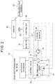
- FIG. 2 is a schematic illustration of a hydraulic circuit of the construction machine in the above exemplary embodiment.
- FIG. 3 is a cross-sectional view showing a structure of an oil filter in the above exemplary embodiment.
- FIG. 4 is a functional block diagram showing a controller and a server in the above exemplary embodiment.
- FIG. 5 is a schematic illustration of a state estimation table in the above exemplary embodiment.
- FIG. 6 is a schematic illustration of time-series maximum oil temperature data in the above exemplary embodiment.
- FIG. 7A is a schematic illustration for explaining a lifetime prediction in the above exemplary embodiment.
- FIG. 7B is a schematic illustration for explaining a case where abnormality occurs in the oil filter in the above exemplary embodiment.
- FIG. 8 is a flow chart showing an estimation method of a filter state in the above exemplary embodiment.
- FIG. 9 is another flow chart showing the estimation method of the filter state in the above exemplary embodiment.
- FIG. 10 is a schematic illustration showing a hydraulic circuit in a construction machine according to a second exemplary embodiment of the invention.
- FIG. 11 is a functional block diagram showing a controller and a monitor in the above exemplary embodiment.
- FIG. 1 shows a hydraulic excavator 1 according an exemplary embodiment of the invention.
- the hydraulic excavator 1 as a construction machine includes an undercarriage 2 , an upper revolving body 3 , and working equipment 5 .
- the undercarriage 2 includes a truck frame (not shown) and a pair of travel devices 2 A provided to both ends of the truck frame in a vehicle width direction orthogonal to a travel direction.
- Each of the travel devices 2 A includes a crawler belt 2 B wound around a drive wheel and an idler wheel provided to the truck frame, and is configured to drive the drive wheel to move the hydraulic excavator 1 forward and backward in an extending direction of the crawler belt 2 B.
- the upper revolving body 3 is rotatably provided on the truck frame of the undercarriage 2 via a swing circle.
- a cab 4 is provided on a front-left side of the upper revolving body 3 in the travel direction.
- the working equipment 5 is provided on a front-center (i.e., next to the cab 4 ) of the upper revolving body 3 .
- a counterweight 3 A is provided on a rear side (i.e., an opposite side from the cab 4 and the working equipment 5 ) of the upper revolving body 3 .
- the counterweight 3 A is provided in order to balance a weight of the hydraulic excavator 1 during a digging operation.
- An operator gets in the cab 4 and operates the hydraulic excavator 1 .
- an operator's seat (not shown in FIG. 1 ) and control levers on both sides of the operator's seat are provided.
- a travel pedal is provided on a floor of the cab 4 .
- the working equipment 5 includes a boom 6 , an arm 7 , a bucket 8 , a boom cylinder 6 A for working the boom 6 , an arm cylinder 7 A for working the arm 7 , and a bucket cylinder 8 A for working the bucket 8 .
- a proximal end of the boom 6 is connected to the upper revolving body 3 so that the boom 6 is movable.
- the boom 6 is vertically moved by extending and contracting the boom cylinder 6 A whose ends are respectively connected to the upper revolving body 3 and the boom 6 .
- a proximal end of the arm 7 is connected to a distal end of the boom 6 so that the arm 7 is movable.
- the arm 7 is vertically moved by extending and contracting the arm cylinder 7 A whose ends are respectively connected to the boom 6 and the arm 7 .
- a proximal end of the bucket 8 is connected to a distal end of the arm 7 so that the bucket 8 is movable.
- the bucket 8 is moved by extending and contracting the bucket cylinder 8 A whose ends are respectively connected to the arm 7 and the bucket 8 .
- the boom cylinder 6 A, the arm cylinder 7 A, and the bucket cylinder 8 A are hydraulic cylinders configured to be driven by a hydraulic oil discharged from a hydraulic pump 12 (see FIG. 2 ).
- FIG. 2 shows a hydraulic circuit 10 provided in the hydraulic excavator 1 in the exemplary embodiment.
- the hydraulic circuit 10 includes a hydraulic oil tank 11 , a hydraulic pump 12 , a control valve 13 , and an oil filter 14 .
- the hydraulic oil tank 11 is configured to feed a hydraulic oil to the hydraulic pump 12 and store a return hydraulic oil after driving the hydraulic cylinders 6 A, 7 A and 8 A.
- the hydraulic pump 12 sucks the hydraulic oil from the hydraulic oil tank 11 and pumps the hydraulic oil to the control valve 13 .
- a position of a spool of the control valve 13 is changed to feed the hydraulic oil to the hydraulic cylinders 6 A, 7 A and 8 A (actuators), thereby extending and contracting the hydraulic cylinders 6 A, 7 A and 8 A to work the boom 6 , the arm 7 , and the bucket 8 .
- the hydraulic oil from the control valve 13 may be fed to a hydraulic motor configured to drive the hydraulic excavator 1 . Subsequently, the hydraulic oil discharged from the hydraulic motor is returned to the hydraulic oil tank 11 via the control valve 13 .
- control valve 13 is also operated in order to return the return hydraulic oil from the hydraulic cylinders 6 A, 7 A and 8 A to the hydraulic oil tank 11 via the oil filter 14 .
- the oil filter 14 is provided in a return pipe from the control valve 13 and is configured to remove foreign substances mixed in the hydraulic oil flowing through the hydraulic circuit 10 .
- the oil filter 14 includes: a filter element 15 ; a bypass channel 16 circumventing the filter element 15 ; and a valve 17 provided in the bypass channel 16 .
- the valve 17 includes a stroke sensor 18 serving as the open-degree sensor. A detection value by the stroke sensor 18 is outputted to a controller 20 .
- a temperature sensor 19 is provided to an intake port of the hydraulic pump 12 . A detection value by the temperature sensor 19 is outputted to the controller 20 .
- the controller 20 serving as a control device is configured to output a control command to each of components of the hydraulic circuit 10 to control the operation of the hydraulic circuit 10 .
- the controller 20 is connected to a monitor 21 and a communication terminal 22 via Control Area Network (CAN) and configured to intercommunicate with the monitor 21 and the communication terminal 22 .
- CAN Control Area Network
- the monitor 21 includes a processor and a display.
- the display displays various data detected by sensors, such as a temperature of an engine cooling water, fuel residual amount, and temperature of the hydraulic oil.
- the communication terminal 22 is configured to output information such as a detection value detected by a sensor and the like, a set value set by the monitor 21 , and a position of the hydraulic excavator 1 detected by Global Positioning System (GPS) 23 .
- the communication terminal 22 outputs the information to a server 24 through a satellite communication line and a portable communication network.
- FIG. 3 shows a detailed structure of the oil filter 14 .
- the oil filter 14 includes a case body 14 A and a lid 14 B.
- the case body 14 A is a cylindrical container and houses the filter element 15 therein.
- a return oil intake port 141 serving as an intake unit is formed on a side surface of the case body 14 A.
- a return pipe extending from the control valve 13 is connected to the return oil intake port 141 , whereby the hydraulic oil returned from the control valve 13 is fed into the case body 14 A.
- a hole 142 serving as a discharge unit is formed at center of the bottom of the case body 14 A.
- the hydraulic oil from which foreign substances are removed by the filter element 15 is fed into the hydraulic oil tank 11 .
- the lid 14 B covers a top surface of the case body 14 A.
- the valve 17 is attached to the center of the lid 14 B.
- the valve 17 has a valve body 17 A.
- a coil spring 14 C is provided under the valve body 17 A in a manner to be disposed coaxially with a cylinder center axis of the case body 14 A.
- the coil spring 14 C biases the filter element 15 downward via a plate 14 D to fix the filter element 15 in the case body 14 A.
- the filter element 15 includes: a filtering medium 15 A formed in a hollow cylinder; and plates 15 B respectively provided to ends in a cylinder axis direction of the filtering medium 15 A.
- the filtering medium 15 A removes foreign substance contained in the hydraulic oil flowing from an outside to an inside in a radial direction.
- the plates 15 B are respectively in contact with the bottom of the case body 14 A and the bottom of the plate 14 D.
- the filter element 15 is held coaxially with the axis of the cylinder of the case body 14 A.
- the filter element 15 is also referred to as a filter.
- the valve 17 includes: a bypass channel 16 through which the hydraulic oil present outside the filter element 15 intercommunicates with the hydraulic oil present inside the filter element 15 ; and a valve body 17 C configured to open and close the bypass channel 16 .
- the valve 17 includes a valve stem 17 B, the valve body 17 C, and a coil spring 17 D.
- the valve 17 is configured to regulate a flow rate of the hydraulic oil flowing through the bypass channel 16 .
- the valve stem 17 B which is formed of a steel-made shaft, is housed in the valve body 17 A and is vertically slidably supported by the valve body 17 A.
- the valve body 17 C is a disc-shaped lid attached to a lower end of the valve stem 17 B.
- the valve body 17 C closes the bypass channel 16 to block the flow of the hydraulic oil.
- the valve stem 17 B is moved downward, a gap is formed between the bypass channel 16 and the valve body 17 C and the hydraulic oil flows through the gap.
- the coil spring 17 D in which the valve stem 17 B is inserted, biases the valve stem 17 B upward.
- the stroke sensor 18 is provided to a top proximal end of the valve stem 17 B.
- the stroke sensor 18 includes: a movable portion 18 A including a magnet 18 B; and a sensor body 18 C.
- the movable portion 18 A is connected to the proximal end of the valve stem 17 B and is configured to vertically slide in conjunction with the sliding of the valve stem 17 B.
- the magnet 18 B is provided to an upper end of the movable portion 18 A and is configured to vertically move in conjunction with the vertical sliding of the movable portion 18 A.
- the sensor body 18 C has a magnetically sensitive element (e.g., Hall IC) therein and is configured to detect a change in a magnetic field caused by the vertical movement of the magnet 18 B.
- a magnetically sensitive element e.g., Hall IC
- the hydraulic oil passes through the filtering medium 15 A of the filter element 15 to remove foreign substance, and subsequently the hydraulic oil is returned to the hydraulic oil tank 11 through the hole 142 on the bottom of the oil filter 14 .
- the movable portion 18 A of the stroke sensor 18 Simultaneously with the downward sliding of the valve stem 17 B, the movable portion 18 A of the stroke sensor 18 also slides downward.
- the sensor body 18 C of the stroke sensor 18 detects the sliding of the movable portion 18 A and outputs this detection in a form of an electric signal, thereby notifying the controller 20 of information that the valve 17 is in an open state.
- FIG. 4 is a functional block diagram showing the controller 20 and the server 24 .
- the controller 20 is configured to acquire detection data by various sensors provided in the hydraulic excavator 1 .
- the controller 20 includes a hydraulic oil temperature acquiring unit 201 , a valve-open/closed state acquiring unit 202 , a position information acquiring unit 203 , and an operation information acquiring unit 204 .
- the hydraulic oil temperature acquiring unit 201 is configured to acquire temperature detection data by the temperature sensor 19 provided in the hydraulic oil tank 11 .
- the valve-open/closed state acquiring unit 202 is configured to acquire detection data on open and closed states of the valve 17 detected by the stroke sensor 18 to detect the open and closed states of the valve 17 . Specifically, the valve-open/closed state acquiring unit 202 acquires the open and closed states of the valve 17 based on whether or not a time when a stroke amount detected by the stroke sensor 18 exceeds a predetermined threshold lasts for a predetermined time.
- the position information acquiring unit 203 acquires a current position of the hydraulic excavator 1 detected by the GPS 23 .
- the operation information acquiring unit 204 acquires the detection data from various sensors provided in the hydraulic excavator 1 to acquire operation information of the hydraulic excavator 1 .
- Examples of the operation information include a temperature of an engine cooling water, a fuel residual amount, and an operation time and an operation fuel efficiency of the hydraulic excavator 1 .
- the controller 20 outputs the acquired information including the hydraulic oil temperature, the open and closed states of the valve 17 and the operation information of the hydraulic excavator 1 to the communication terminal 22 .
- the server 24 receives various information outputted from the communication terminal 22 and stores the information therein.
- the server 24 includes a memory 24 A, a data storage 240 , a state estimating unit 241 , a lifetime predicting unit 242 , and a replacement judging unit 243 .
- the memory 24 A is configured to store various table data described later.
- the state estimating unit 241 is configured to estimate a clogging state of the filter element 15 based on the maximum oil temperature in the open state of the valve 17 . Specifically, as shown in FIG. 5 , the state estimating unit 241 estimates a clogging rate of the filter element 15 based on the maximum oil temperature in the open state of the valve 17 , in view of a state estimation table showing a relationship between the maximum oil temperature in the valve open state and the clogging rate of the filter element 15 .
- the maximum oil temperature in the open state of the valve 17 means the maximum temperature of the hydraulic oil obtained by constantly detecting a hydraulic oil temperature in the open state of the valve 17 and acquiring the maximum temperature during a predetermined elapsed time (e.g., 10 hours). Since a viscosity of the oil is low at a high temperature, a differential pressure is generally unlikely to be caused at a high temperature. However, when the clogging of the filter element 15 progresses, the differential pressure becomes large even at the high temperature.
- the data storage 240 is configured to store the maximum oil temperature data in the open state of the valve 17 in time-series as shown in FIG. 6 , and output the results to the lifetime predicting unit 242 and the replacement judging unit 243 .
- the lifetime predicting unit 242 is configured to predict a lifetime of the filter element 15 based on a transition of a state of the filter element 15 in the open state of the valve 17 with reference to the monitor result of the maximum oil temperature of the state estimating unit 241 .
- the lifetime of the filter is estimated by obtaining a time when the maximum oil temperature in the open state of the valve 17 reaches a temperature of a clogging alarm level (e.g., 40 degrees C.) based on a time-series change between the maximum oil temperature in the open state of the valve 17 at a current time and the maximum oil temperature in the open state of the valve 17 close to the current time.
- a clogging alarm level e.g. 40 degrees C.
- the lifetime of the filter element 15 as of a time t 1 in FIG. 7A is defined by a time T_remain representing a time from the time t 1 to a time t 2 .
- the time T_remain is estimated by calculating (e.g., extrapolating) the time t 2 when the maximum oil temperature reaches the clogging alarm level based on a change in the maximum oil temperature between the time t 1 and a time t 0 close to the time t 1 .
- the lifetime predicting unit 242 judges that abnormality has occurred in the filter element 15 .
- the replacement judging unit 243 is configured to judge whether the filter element 15 has been replaced or not based on the maximum oil temperature time-series data in the valve open state outputted by the data storage 240 . Specifically, when the maximum oil temperature in the open state of the valve 17 is sharply declined to a predetermined value or less, the replacement judging unit 243 judges that the filter element 15 has been replaced.
- a time t 3 and a time t 5 are judged as a replacement time of the filter element 15 .
- a predetermined operation time e.g. 1000 hours
- a message of encouraging the replacement of the filter element 15 is displayed on the monitor 21 and the like.
- a replacement time is also displayed as a history on the monitor 21 and the like.
- the controller 20 repeatedly executes a series of processings shown in the flowcharts in a predetermined cycle (e.g., a 0.01 second cycle). It should be noted that, even when an operation state and an operation load of the working equipment 5 in the hydraulic excavator 1 are changed, an amount of the hydraulic oil flowing into the filter element 15 is averaged within a predetermined time and a fluctuation in the amount of the hydraulic oil caused by the operation of the working equipment 5 can be ignored.
- a predetermined cycle e.g. 0.01 second cycle
- the measurement of the maximum oil temperature is triggered by the start of the engine in the exemplary embodiment, the measurement of the maximum oil temperature may be triggered by a judgment of the valve 17 being in the open state due to another reason.
- the controller 20 judges whether the maximum oil temperature in the open state of the valve 17 , a duration when the valve 17 is in the open state, and a position of the valve 17 in a closed state are initialized or not (Step S 1 ).
- the hydraulic oil temperature acquiring unit 201 initializes the maximum oil temperature T_max in the open state of the valve 17 to, for instance, ⁇ 100 degrees C.
- the valve-open/closed state acquiring unit 202 initializes an open-state duration OpenTime of the valve to zero seconds and initializes a valve-stroke closed position L_ 0 to 0 mm (Step S 2 ).
- the controller 20 judges whether or not the time elapsed after the start of the engine exceeds a processing-start judging time (e.g., three minutes) (Step S 3 ).
- a processing-start judging time e.g., three minutes
- the valve-open/closed state acquiring unit 202 measures a stroke L of the valve 17 by the stroke sensor 18 (Step S 4 ).
- the valve-open/closed state acquiring unit 202 judges whether or not the control lever is at a neutral position (Step S 5 ).
- Step S 7 When the control lever is not at a neutral position (S 5 : No), the procedure proceeds to Step S 7 .
- valve-open/closed state acquiring unit 202 automatically corrects the valve-stroke closed position L_ 0 to the stroke L measured at the current time by the stroke sensor 18 (Step S 6 ).
- the valve-open/closed state acquiring unit 202 judges whether or not a difference between the stroke L measured by the stroke sensor 18 and the valve-stroke closed position L_ 0 is larger than a stroke (e.g., 0.3 mm) for judging whether the valve 17 is opened (hereinafter, also referred to as an open-state judging stroke) (Step S 7 ).
- a stroke e.g., 0.3 mm
- valve-open/closed state acquiring unit 202 When judging that the difference is smaller than the open-state judging stroke (S 7 : No), the valve-open/closed state acquiring unit 202 resets the open-state duration OpenTime of the valve 17 to zero (Step S 8 ) to finish the processing.
- the valve-open/closed state acquiring unit 202 adds a calculation cycle (e.g., 0.01 seconds) to the open-state duration OpenTime of the valve 17 to update the open-state duration OpenTime of the valve 17 (Step S 9 ).
- a calculation cycle e.g. 0.01 seconds
- the valve-open/closed state acquiring unit 202 judges whether or not the open-state duration OpenTime of the valve 17 exceeds a time (e.g., 1 second) for judging a valve open state (Step S 10 ).
- the hydraulic oil temperature acquiring unit 201 measures a hydraulic oil temperature T using the temperature sensor 19 (Step S 11 ).
- the hydraulic oil temperature acquiring unit 201 judges whether or not the acquired hydraulic oil temperature T exceeds the maximum oil temperature T_max (Step S 12 ).
- the hydraulic oil temperature acquiring unit 201 updates the maximum oil temperature T_max to the measured hydraulic oil temperature T (Step S 13 ).
- the hydraulic oil temperature acquiring unit 201 judges whether the measured hydraulic oil temperature T exceeds an alarm oil temperature (e.g., 40 degrees C.) (Step S 14 ).
- an alarm oil temperature e.g. 40 degrees C.
- Step S 16 When the measured hydraulic oil temperature T is equal to or less than the alarm oil temperature, the procedure proceeds to Step S 16 .
- the hydraulic oil temperature acquiring unit 201 When the measured hydraulic oil temperature T exceeds the alarm oil temperature, the hydraulic oil temperature acquiring unit 201 outputs the information to the monitor 21 and the monitor 21 displays a clogging alarm showing the filter element 15 being in a clogged state (Step S 15 ).
- the communication terminal 22 judges whether to output the maximum oil temperature T_max and the open-state duration OpenTime of the valve 17 which are acquired by the controller 20 to the server 24 , together with the position information acquired by the position information acquiring unit 203 and the operation information acquired by the operation information acquiring unit 204 (Step S 16 ).
- Step S 16 When the communication terminal 22 judges that it is not time to output the information (Step S 16 : No), the processing is finished.
- the communication terminal 22 When judging that it is time to output the information, the communication terminal 22 outputs the maximum oil temperature T_max and the open-state duration OpenTime of the valve 17 to the server 24 (Step S 17 ).
- the timing for outputting the information can be set as needed, for instance, every 20 hours of the operation time.
- the communication terminal 22 may output the above information at the time t 4 .
- the state estimating unit 241 estimates the clogging state of the filter element 15 based on the maximum oil temperature T_max and the open-state duration OpenTime of the valve 17 outputted from the communication terminal 22 , and the data storage 240 stores the maximum oil temperature T_max and the open-state duration OpenTime in time-series.
- the lifetime predicting unit 242 predicts the lifetime of the filter element 15 based on the time-series change in the maximum oil temperature in the open state of the valve 17 . Further, when the maximum oil temperature in the open state of the valve 17 is sharply declined to a predetermined value or less, the replacement judging unit 243 judges that the filter element 15 has been replaced.
- the temperature sensor 19 can detect the hydraulic oil temperature when the stroke sensor 18 detects that the valve 17 in the bypass channel 16 is in the open state. Accordingly, when the server 24 analyzes the transition of the maximum oil temperature in the open state of the valve 17 , the server 24 can estimate the clogging state of the filter element 15 , predict the lifetime of the filter element 15 , and judge whether the filter element 15 has been replaced or not.
- the detection result of the open or closed state of the valve 17 which is detected by the sensor and the like and the detection result of the temperature by the temperature sensor 19 are outputted via the communication terminal 22 to the server 24 .
- the second exemplary embodiment is different from the first exemplary embodiment in that a monitor 31 processes the detection result of the open or closed state of the valve 17 and the detection result of the temperature by the temperature sensor 19 .
- the monitor 31 displays various data detected by sensors, such as a temperature of the engine cooling water, fuel residual amount, and temperature of the hydraulic oil.
- the monitor 31 includes a processor 31 A, a memory 31 B, and a display 31 C.
- the processor 31 A includes a data storage 310 , a state estimating unit 311 , a lifetime predicting unit 312 , a replacement judging unit 313 , and an alarm generator 314 , which have the same functions as those in the first exemplary embodiment. Moreover, a state estimation table is stored in the memory 31 B in the same manner as in the first exemplary embodiment.
- the state estimating unit 311 estimates the clogging state of the filter element 15 based on the temperature detection result detected by the temperature sensor 19 in view of the table stored in the memory 31 B.
- the state estimating unit 311 generates image information indicating how far (e.g., to a high, intermediate, or low degree) the clogging state of the filter element 15 progresses, and displays the image information on the display 31 C.
- the image information to be displayed is not limited to the above, but may be an image indicating the clogging degree in percentage terms.
- the data storage 310 is configured to store the maximum oil temperature data of the valve 17 in time-series and outputs the results to the lifetime predicting unit 312 and the replacement judging unit 313 , in the same manner as in the first exemplary embodiment.
- the lifetime predicting unit 312 is configured to predict a lifetime of the filter element 15 based on the maximum oil temperature in the open state of the valve 17 with reference to the monitor result of the maximum oil temperature of the state estimating unit 311 .
- a predicting method is the same as in the first exemplary embodiment.
- the replacement judging unit 313 is configured to judge that the filter element 15 has been replaced based on the state estimation of the filter element 15 by the state estimating unit 311 .
- the alarm generator 314 displays a clogging alarm on the display 31 C when the hydraulic oil temperature detected by the temperature sensor 19 exceeds the alarm oil temperature. It should be noted that the clogging state is not only displayed on the display 31 C, but may be informed using an alarming sound.
- the monitor 31 of the hydraulic excavator 1 estimates the state of the filter element 15 , the clogging of the filter element 15 can be managed in a stand-alone manner, thereby avoiding complication of the system.
- the filter state estimation system is applied to the hydraulic excavator 1 .
- application of the system is not limited thereto.
- the filter state estimation system may be applied to other construction machines such as a wheel loader and a bulldozer.
- the temperature sensor 19 is provided near the intake port of the hydraulic pump 12 .
- the location of the temperature sensor 19 is not limited thereto.
- the temperature sensor may be provided inside the hydraulic oil tank 11 or may be provided near the hole 142 under the filter element 15 .
- the stroke sensor 18 is used for detecting the opening and closing of the valve 17 .
- the detector is not limited to the stroke sensor, but may be an optical sensor such as an encoder.
- operation information acquiring unit 240 . . . data storage, 241 . . . state estimating unit, 242 . . . lifetime predicting unit, 243 . . . replacement judging unit, 310 . . . data storage, 311 . . . state estimating unit, 312 . . . lifetime predicting unit, 313 . . . replacement judging unit, 314 . . . alarm generator.
Landscapes
- Engineering & Computer Science (AREA)
- Chemical & Material Sciences (AREA)
- Chemical Kinetics & Catalysis (AREA)
- General Engineering & Computer Science (AREA)
- Structural Engineering (AREA)
- Civil Engineering (AREA)
- Mining & Mineral Resources (AREA)
- Analytical Chemistry (AREA)
- Physics & Mathematics (AREA)
- Fluid Mechanics (AREA)
- Mechanical Engineering (AREA)
- Fluid-Pressure Circuits (AREA)
- Filtration Of Liquid (AREA)
- Component Parts Of Construction Machinery (AREA)
- Indication Of The Valve Opening Or Closing Status (AREA)
Abstract
Description
Claims (7)
Applications Claiming Priority (1)
| Application Number | Priority Date | Filing Date | Title |
|---|---|---|---|
| PCT/JP2017/022363 WO2017191852A1 (en) | 2017-06-16 | 2017-06-16 | Filter status estimation system and filter status estimation method |
Publications (2)
| Publication Number | Publication Date |
|---|---|
| US20180361283A1 US20180361283A1 (en) | 2018-12-20 |
| US10695699B2 true US10695699B2 (en) | 2020-06-30 |
Family
ID=60203707
Family Applications (1)
| Application Number | Title | Priority Date | Filing Date |
|---|---|---|---|
| US15/577,942 Active 2037-08-19 US10695699B2 (en) | 2017-06-16 | 2017-06-16 | Filter state estimation system and filter state estimation method |
Country Status (5)
| Country | Link |
|---|---|
| US (1) | US10695699B2 (en) |
| JP (1) | JP6311080B1 (en) |
| CN (1) | CN107660259B (en) |
| DE (1) | DE112017000028B4 (en) |
| WO (1) | WO2017191852A1 (en) |
Cited By (1)
| Publication number | Priority date | Publication date | Assignee | Title |
|---|---|---|---|---|
| SE2450430A1 (en) * | 2024-04-22 | 2025-10-23 | Husqvarna Ab | A demolition robot with a hydraulic system monitoring function |
Families Citing this family (13)
| Publication number | Priority date | Publication date | Assignee | Title |
|---|---|---|---|---|
| JP2019163794A (en) * | 2018-03-19 | 2019-09-26 | いすゞ自動車株式会社 | Detection device |
| DE102018214923A1 (en) * | 2018-09-03 | 2020-03-05 | Rolls-Royce Deutschland Ltd & Co Kg | Monitoring of servo valve filter elements |
| CN109595743B (en) * | 2018-10-16 | 2022-03-04 | 珠海格力电器股份有限公司 | Filter screen cleaning reminding method, device and equipment |
| JP7198070B2 (en) * | 2018-12-11 | 2022-12-28 | ヤマシンフィルタ株式会社 | Filter life predictor |
| KR20210126724A (en) * | 2019-02-19 | 2021-10-20 | 가부시키가이샤 후지킨 | valve |
| DE102019106977B4 (en) * | 2019-03-19 | 2024-04-04 | Argo-Hytos Group Ag | Arrangement with a filter device and a carrier element and method for detecting a filter element |
| DE102020200388A1 (en) | 2020-01-14 | 2021-07-15 | Zf Friedrichshafen Ag | Device and method for determining the loading state of a filter |
| JP7455632B2 (en) * | 2020-03-30 | 2024-03-26 | 住友重機械工業株式会社 | Excavators and shovel management devices |
| DE102020204488B4 (en) | 2020-04-07 | 2023-11-02 | Zf Friedrichshafen Ag | Method and evaluation system for determining a filter contamination condition, as well as filter system and machine |
| CN111425488A (en) * | 2020-05-13 | 2020-07-17 | 三一重机有限公司 | Hydraulic oil temperature control system and excavator |
| JP7767190B2 (en) * | 2022-03-15 | 2025-11-11 | 株式会社小松製作所 | Oil filter device |
| JP7767191B2 (en) * | 2022-03-15 | 2025-11-11 | 株式会社小松製作所 | Oil filter device |
| CN114876916B (en) * | 2022-04-28 | 2025-06-17 | 索特传动设备有限公司 | Oil return filter and construction machinery |
Citations (14)
| Publication number | Priority date | Publication date | Assignee | Title |
|---|---|---|---|---|
| JPS4895026A (en) | 1972-03-17 | 1973-12-06 | ||
| JPS499303A (en) | 1972-05-26 | 1974-01-26 | ||
| JPS5910402A (en) | 1982-07-10 | 1984-01-19 | Toshiba Corp | Rolling mill and rolling method |
| JPS602526A (en) | 1983-05-23 | 1985-01-08 | Chuo Kakoki Kk | Conveying method of pulverulent body by diaphragm pump |
| JPH0651508A (en) | 1992-06-01 | 1994-02-25 | Ocg Microelectron Materials Inc | Dyeed positive i-line photosensitive mixture |
| JPH0734491A (en) | 1993-07-20 | 1995-02-03 | Hitachi Constr Mach Co Ltd | Filter clogging detector for construction machinery |
| JP2001038114A (en) | 1999-08-02 | 2001-02-13 | Saginomiya Seisakusho Inc | Hydraulic filter monitoring system and hydraulic filter monitoring method |
| JP3499303B2 (en) | 1994-10-07 | 2004-02-23 | 山信工業株式会社 | Filtration device with differential pressure indicator |
| DE10357217A1 (en) | 2003-12-08 | 2005-07-07 | Sauer-Danfoss (Neumünster) GmbH & Co OHG | Arrangement for filtering hydraulic fluid |
| US7174273B2 (en) * | 2005-05-11 | 2007-02-06 | Hamilton Sundstrand Corporation | Filter monitoring system |
| DE102007037525A1 (en) | 2007-08-09 | 2009-02-12 | Joma-Polytec Kunststofftechnik Gmbh | Oil filter system for internal combustion engine of motor vehicle, has filter element arrangement operated in different operating positions with filter effects, and controller for controlling arrangement depending on degree of contamination |
| JP2011085215A (en) | 2009-10-16 | 2011-04-28 | Caterpillar Sarl | Hydraulic oil tank of working vehicle |
| JP2013000608A (en) | 2011-06-10 | 2013-01-07 | Komatsu Ltd | Oil filter |
| DE102012017059A1 (en) | 2012-08-29 | 2014-03-06 | Robert Bosch Gmbh | Filter arrangement for oil filtration, particularly for hydraulic- and lubricating oil filtration, has oil inlet for supplying oil to be filtered to filter element, and oil outlet that is downstream to filter element |
Family Cites Families (8)
| Publication number | Priority date | Publication date | Assignee | Title |
|---|---|---|---|---|
| JPS602526B2 (en) * | 1979-06-15 | 1985-01-22 | 株式会社クボタ | Work vehicle safety equipment |
| DE4011913A1 (en) * | 1990-04-12 | 1991-10-17 | Beyer Rudi Dipl Ing | Hydraulic system with filter - separates out fine particles by channelling part of flow through by=pass line |
| JPH081282Y2 (en) * | 1991-11-18 | 1996-01-17 | 株式会社新潟鉄工所 | Filter clogging alarm device |
| DE29705018U1 (en) * | 1996-06-26 | 1997-05-15 | Hydac Technology Gmbh, 66280 Sulzbach | Thermal bypass valve |
| ITRE20050036A1 (en) * | 2005-04-06 | 2006-10-07 | Ufi Filters Spa | REFINED DIESEL FUEL FILTER |
| BRPI0722165A2 (en) * | 2007-10-19 | 2014-03-18 | Mp Filtri S P A | PRESSURE OIL FILTERING DEVICE |
| JP2011190738A (en) * | 2010-03-15 | 2011-09-29 | Iseki & Co Ltd | Diesel particulate filter regeneration control device for combine harvester |
| CN205047584U (en) * | 2015-06-30 | 2016-02-24 | 常州福宇精密模具有限公司 | Aviation hydraulic fluid purifier |
-
2017
- 2017-06-16 US US15/577,942 patent/US10695699B2/en active Active
- 2017-06-16 WO PCT/JP2017/022363 patent/WO2017191852A1/en not_active Ceased
- 2017-06-16 DE DE112017000028.9T patent/DE112017000028B4/en active Active
- 2017-06-16 JP JP2017550788A patent/JP6311080B1/en active Active
- 2017-06-16 CN CN201780001602.0A patent/CN107660259B/en active Active
Patent Citations (14)
| Publication number | Priority date | Publication date | Assignee | Title |
|---|---|---|---|---|
| JPS4895026A (en) | 1972-03-17 | 1973-12-06 | ||
| JPS499303A (en) | 1972-05-26 | 1974-01-26 | ||
| JPS5910402A (en) | 1982-07-10 | 1984-01-19 | Toshiba Corp | Rolling mill and rolling method |
| JPS602526A (en) | 1983-05-23 | 1985-01-08 | Chuo Kakoki Kk | Conveying method of pulverulent body by diaphragm pump |
| JPH0651508A (en) | 1992-06-01 | 1994-02-25 | Ocg Microelectron Materials Inc | Dyeed positive i-line photosensitive mixture |
| JPH0734491A (en) | 1993-07-20 | 1995-02-03 | Hitachi Constr Mach Co Ltd | Filter clogging detector for construction machinery |
| JP3499303B2 (en) | 1994-10-07 | 2004-02-23 | 山信工業株式会社 | Filtration device with differential pressure indicator |
| JP2001038114A (en) | 1999-08-02 | 2001-02-13 | Saginomiya Seisakusho Inc | Hydraulic filter monitoring system and hydraulic filter monitoring method |
| DE10357217A1 (en) | 2003-12-08 | 2005-07-07 | Sauer-Danfoss (Neumünster) GmbH & Co OHG | Arrangement for filtering hydraulic fluid |
| US7174273B2 (en) * | 2005-05-11 | 2007-02-06 | Hamilton Sundstrand Corporation | Filter monitoring system |
| DE102007037525A1 (en) | 2007-08-09 | 2009-02-12 | Joma-Polytec Kunststofftechnik Gmbh | Oil filter system for internal combustion engine of motor vehicle, has filter element arrangement operated in different operating positions with filter effects, and controller for controlling arrangement depending on degree of contamination |
| JP2011085215A (en) | 2009-10-16 | 2011-04-28 | Caterpillar Sarl | Hydraulic oil tank of working vehicle |
| JP2013000608A (en) | 2011-06-10 | 2013-01-07 | Komatsu Ltd | Oil filter |
| DE102012017059A1 (en) | 2012-08-29 | 2014-03-06 | Robert Bosch Gmbh | Filter arrangement for oil filtration, particularly for hydraulic- and lubricating oil filtration, has oil inlet for supplying oil to be filtered to filter element, and oil outlet that is downstream to filter element |
Non-Patent Citations (3)
| Title |
|---|
| German Office Action in German Application No. 112017000028.9, dated Dec. 2, 2018, 7 pages. |
| International Search Report in International Application No. PCT/JP2017/022363, dated Aug. 8, 2017, 8 pages (with English translation). |
| Japan Office Action in Japan Application No. 2017-550788, dated Dec. 12, 2017, 5 pages (with English translation). |
Cited By (1)
| Publication number | Priority date | Publication date | Assignee | Title |
|---|---|---|---|---|
| SE2450430A1 (en) * | 2024-04-22 | 2025-10-23 | Husqvarna Ab | A demolition robot with a hydraulic system monitoring function |
Also Published As
| Publication number | Publication date |
|---|---|
| CN107660259A (en) | 2018-02-02 |
| WO2017191852A1 (en) | 2017-11-09 |
| JP6311080B1 (en) | 2018-04-11 |
| US20180361283A1 (en) | 2018-12-20 |
| CN107660259B (en) | 2022-03-29 |
| DE112017000028B4 (en) | 2019-07-18 |
| JPWO2017191852A1 (en) | 2018-05-17 |
| DE112017000028T5 (en) | 2018-01-11 |
Similar Documents
| Publication | Publication Date | Title |
|---|---|---|
| US10695699B2 (en) | Filter state estimation system and filter state estimation method | |
| US10597852B2 (en) | Wheel loader and method for automically accumulating transport operation information of wheel loader | |
| JP5651099B2 (en) | Plunger pump failure diagnosis device | |
| AU2008312088B2 (en) | Method and arrangement for detecting leakage of hydraulic oil | |
| CN108966665B (en) | Hydraulic control system for working machine | |
| US11401700B2 (en) | Hydraulic oil monitoring system and hydraulic oil monitoring method | |
| US8718880B2 (en) | Hydraulic system calibration method and apparatus | |
| US9145657B2 (en) | System for controlling land leveling work which uses an excavator | |
| US11136743B2 (en) | Electric construction machine | |
| CN104169629A (en) | Systems and methods for monitoring a fluid system of a mining machine | |
| EP4008842B1 (en) | Work machine | |
| US20170073937A1 (en) | Fuel Device Water Separation System For Industrial Machine | |
| JP2020143591A (en) | Hydraulic pump failure diagnosis device, construction machinery equipped with failure diagnosis device, failure diagnosis method and failure diagnosis program | |
| WO2020027135A1 (en) | Work machine | |
| SE1050076A1 (en) | Method for cleaning hydraulic fluid, computer program product, control unit and industrial truck | |
| JP4088149B2 (en) | Abnormality monitoring method for hydraulic system | |
| US12163825B2 (en) | Work machine | |
| JP2026009596A (en) | Filter abnormality detection device | |
| JP6903567B2 (en) | Work vehicle | |
| CN121025014A (en) | A hydraulic fault detection system and an excavator | |
| CN112744207A (en) | Vehicle braking system, vehicle and vehicle control method | |
| JP2021038608A (en) | Work machine control device | |
| CN110295643A (en) | It determines the method for the circulation time of actuator and determines the system with the mechanical circulation time of actuator |
Legal Events
| Date | Code | Title | Description |
|---|---|---|---|
| AS | Assignment |
Owner name: KOMATSU LTD., JAPAN Free format text: ASSIGNMENT OF ASSIGNORS INTEREST;ASSIGNORS:YOKOYAMA, YUUKI;KAGEYAMA, MASATO;REEL/FRAME:044250/0083 Effective date: 20170926 |
|
| FEPP | Fee payment procedure |
Free format text: ENTITY STATUS SET TO UNDISCOUNTED (ORIGINAL EVENT CODE: BIG.); ENTITY STATUS OF PATENT OWNER: LARGE ENTITY |
|
| AS | Assignment |
Owner name: KOMATSU LTD., JAPAN Free format text: CORRECTIVE ASSIGNMENT TO CORRECT THE TYPOGRAPHICAL ERROR IN THE WORD "ESTIMATION" IN THE TITLE OF THE INVENTION PREVIOUSLY RECORDED ON REEL 044250 FRAME 0083. ASSIGNOR(S) HEREBY CONFIRMS THE SPELLING OF "ESTMIATION" SHOULD BE "ESTIMATION";ASSIGNORS:YOKOYAMA, YUUKI;KAGEYAMA, MASATO;REEL/FRAME:045073/0003 Effective date: 20170926 |
|
| STPP | Information on status: patent application and granting procedure in general |
Free format text: DOCKETED NEW CASE - READY FOR EXAMINATION |
|
| STPP | Information on status: patent application and granting procedure in general |
Free format text: NON FINAL ACTION MAILED |
|
| STPP | Information on status: patent application and granting procedure in general |
Free format text: RESPONSE TO NON-FINAL OFFICE ACTION ENTERED AND FORWARDED TO EXAMINER |
|
| STPP | Information on status: patent application and granting procedure in general |
Free format text: FINAL REJECTION MAILED |
|
| STPP | Information on status: patent application and granting procedure in general |
Free format text: DOCKETED NEW CASE - READY FOR EXAMINATION |
|
| STPP | Information on status: patent application and granting procedure in general |
Free format text: NOTICE OF ALLOWANCE MAILED -- APPLICATION RECEIVED IN OFFICE OF PUBLICATIONS |
|
| STPP | Information on status: patent application and granting procedure in general |
Free format text: PUBLICATIONS -- ISSUE FEE PAYMENT RECEIVED |
|
| STCF | Information on status: patent grant |
Free format text: PATENTED CASE |
|
| MAFP | Maintenance fee payment |
Free format text: PAYMENT OF MAINTENANCE FEE, 4TH YEAR, LARGE ENTITY (ORIGINAL EVENT CODE: M1551); ENTITY STATUS OF PATENT OWNER: LARGE ENTITY Year of fee payment: 4 |