WO2017187737A1 - Dispositif de décapage et procédé d'opération de décapage en pause - Google Patents
Dispositif de décapage et procédé d'opération de décapage en pause Download PDFInfo
- Publication number
- WO2017187737A1 WO2017187737A1 PCT/JP2017/006557 JP2017006557W WO2017187737A1 WO 2017187737 A1 WO2017187737 A1 WO 2017187737A1 JP 2017006557 W JP2017006557 W JP 2017006557W WO 2017187737 A1 WO2017187737 A1 WO 2017187737A1
- Authority
- WO
- WIPO (PCT)
- Prior art keywords
- pickling
- acid solution
- tank
- pickling tank
- liquid level
- Prior art date
Links
Images


Classifications
-
- C—CHEMISTRY; METALLURGY
- C23—COATING METALLIC MATERIAL; COATING MATERIAL WITH METALLIC MATERIAL; CHEMICAL SURFACE TREATMENT; DIFFUSION TREATMENT OF METALLIC MATERIAL; COATING BY VACUUM EVAPORATION, BY SPUTTERING, BY ION IMPLANTATION OR BY CHEMICAL VAPOUR DEPOSITION, IN GENERAL; INHIBITING CORROSION OF METALLIC MATERIAL OR INCRUSTATION IN GENERAL
- C23G—CLEANING OR DE-GREASING OF METALLIC MATERIAL BY CHEMICAL METHODS OTHER THAN ELECTROLYSIS
- C23G3/00—Apparatus for cleaning or pickling metallic material
- C23G3/02—Apparatus for cleaning or pickling metallic material for cleaning wires, strips, filaments continuously
- C23G3/021—Apparatus for cleaning or pickling metallic material for cleaning wires, strips, filaments continuously by dipping
-
- C—CHEMISTRY; METALLURGY
- C23—COATING METALLIC MATERIAL; COATING MATERIAL WITH METALLIC MATERIAL; CHEMICAL SURFACE TREATMENT; DIFFUSION TREATMENT OF METALLIC MATERIAL; COATING BY VACUUM EVAPORATION, BY SPUTTERING, BY ION IMPLANTATION OR BY CHEMICAL VAPOUR DEPOSITION, IN GENERAL; INHIBITING CORROSION OF METALLIC MATERIAL OR INCRUSTATION IN GENERAL
- C23G—CLEANING OR DE-GREASING OF METALLIC MATERIAL BY CHEMICAL METHODS OTHER THAN ELECTROLYSIS
- C23G1/00—Cleaning or pickling metallic material with solutions or molten salts
- C23G1/02—Cleaning or pickling metallic material with solutions or molten salts with acid solutions
- C23G1/08—Iron or steel
-
- C—CHEMISTRY; METALLURGY
- C23—COATING METALLIC MATERIAL; COATING MATERIAL WITH METALLIC MATERIAL; CHEMICAL SURFACE TREATMENT; DIFFUSION TREATMENT OF METALLIC MATERIAL; COATING BY VACUUM EVAPORATION, BY SPUTTERING, BY ION IMPLANTATION OR BY CHEMICAL VAPOUR DEPOSITION, IN GENERAL; INHIBITING CORROSION OF METALLIC MATERIAL OR INCRUSTATION IN GENERAL
- C23G—CLEANING OR DE-GREASING OF METALLIC MATERIAL BY CHEMICAL METHODS OTHER THAN ELECTROLYSIS
- C23G3/00—Apparatus for cleaning or pickling metallic material
- C23G3/02—Apparatus for cleaning or pickling metallic material for cleaning wires, strips, filaments continuously
- C23G3/025—Details of the apparatus, e.g. linings or sealing means
-
- C—CHEMISTRY; METALLURGY
- C23—COATING METALLIC MATERIAL; COATING MATERIAL WITH METALLIC MATERIAL; CHEMICAL SURFACE TREATMENT; DIFFUSION TREATMENT OF METALLIC MATERIAL; COATING BY VACUUM EVAPORATION, BY SPUTTERING, BY ION IMPLANTATION OR BY CHEMICAL VAPOUR DEPOSITION, IN GENERAL; INHIBITING CORROSION OF METALLIC MATERIAL OR INCRUSTATION IN GENERAL
- C23G—CLEANING OR DE-GREASING OF METALLIC MATERIAL BY CHEMICAL METHODS OTHER THAN ELECTROLYSIS
- C23G3/00—Apparatus for cleaning or pickling metallic material
- C23G3/02—Apparatus for cleaning or pickling metallic material for cleaning wires, strips, filaments continuously
- C23G3/027—Associated apparatus, e.g. for pretreating or after-treating
Definitions
- the present invention relates to a pickling apparatus and a method for operating the pickling temporarily.
- the pickling apparatus is an apparatus that cleans and removes oxide scale, which is an oxide formed on the surface of a strip steel sheet such as a cold-rolled steel sheet or a hot-rolled steel sheet, by reacting with an acid solution such as hydrochloric acid or sulfuric acid.
- oxide scale is an oxide formed on the surface of a strip steel sheet such as a cold-rolled steel sheet or a hot-rolled steel sheet, by reacting with an acid solution such as hydrochloric acid or sulfuric acid.
- a strip steel plate is continuously passed through the pickling tank, and an acid solution is sprayed onto the strip steel plate, or the strip plate is immersed in an acid solution stored in the pickling bath.
- oxide scale on the surface of the steel strip is continuously removed.
- Patent Document 1 is composed of an acid solution receiving tank that is horizontally long in the running direction of the steel strip, shallow at the center in the longitudinal direction, and deep at both the entrance and exit ends, and a tank lid that covers this.
- Acid pickling tanks weirs provided at the bottom of the acid solution receiving tank at both ends of the central part, a plurality of support rolls provided between the weirs, and a steel strip supported by the support rolls.
- a pickling device that performs pickling continuously by spraying an acid solution onto a steel strip.
- a pickling tank filled with an acid solution a lid that covers the top of the pickling tank, a dipping guide roll that is rotatably provided on the lower surface of the lid, and a bottom surface of the pickling tank.
- JP 2004-91856 A Japanese Patent No. 3160300
- the running of the steel strip is temporarily stopped (for example, from several hours to one day) due to maintenance of devices arranged upstream or downstream in the running direction of the steel strip.
- the pickling of the strip steel plate proceeds and becomes a per-acid wash. Treatments such as transferring the acid solution in the pickling tank to the circulation tank and lifting the steel strip above the acid solution have been performed.
- the acid solution in the pickling tank is transferred to the circulation tank when the pickling is temporarily stopped, so that the steel strip is prevented from being pickled, and the pickling operation is performed by a heat exchanger during the pickling operation.
- the temperature of the acid solution decreased according to the pickling stop time, and it took a long time to switch from the pickling pause to the pickling operation.
- the present invention was made in order to solve the above-described problems, and prevents the steel strip from being over pickled during suspension of pickling, and switching between pickling operation and pickling pause. It aims at providing the pickling apparatus which can shorten time, and the operation method at the time of the pickling temporary stop.
- the pickling apparatus for solving the above-described problems is The pickling tank for pickling the band steel sheet by allowing the acid liquid to be stored and letting the band steel sheet pass through in a state immersed in the acid solution, Heating means for heating the acid solution in the pickling tank; Provided separately from the pickling tank, an acid solution storage tank for storing the acid solution, Acid solution circulating means for circulating the acid solution between the pickling tank and the acid solution storage tank; Liquid level height adjusting means for controlling the acid liquid circulation means to hold the level of the acid liquid in the pickling tank below the sheet plate height of the strip steel plate.
- the operation method at the time of pickling suspension of the pickling apparatus that solves the above-described problems
- the pickling tank and the acid pickling tank are kept in a state where the level of the acid solution in the pickling bath is held below the plate passing height of the steel strip.
- the acid solution circulates between the liquid storage tanks, and over-acid washing of the steel strip at this time can be prevented.
- the acid solution is heated to a predetermined temperature by the heating means, and the acid solution is circulated between the pickling tank and the acid solution storage tank by the acid solution circulation means, the entire amount of the acid solution is pickled. Compared with the case where the tank is discharged from the tank and stored in a tank separate from the pickling tank, the switching time between the pickling operation and the pickling pause can be shortened.
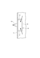
- FIG. 2 is a sectional view taken along the line II-II in FIG.
- FIG. 3 is a cross-sectional view taken along the line III-III in FIG.
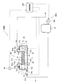
- FIG. 5 is a VV cross-sectional view of FIG. 4.
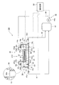
- the pickling apparatus 100 includes a pickling tank 10, a circulation tank (acid solution storage tank) 43, an acid solution circulation device (acid solution circulation means) 40, and And a control device (liquid level height adjusting means) 50.
- the pickling tank 10 is a deep bottom tank.
- the pickling tank 10 includes a bottom plate 11, a front side plate 12, a rear side plate 13, a right side plate 14, and a left side plate 15. Cover member 25 (four in the illustrated example).
- the bottom plate 11 extends in the sheet passing direction (traveling direction) of the steel strip S, and is provided with a gradient so as to be the lowest point at a first discharge port 15b (central circulation port) described later in detail. .
- the front side plate 12, the rear side plate 13, the right side plate 14, and the left side plate 15 form a vertical wall of the pickling tank 10.
- a rubber lining is applied to an acid-resistant material such as a resin such as polypropylene or a composite material thereof, or a steel can body, and an acid-resistant brick is formed thereon. It is possible to use what was done.
- the front side plate 12 is connected to the front end portion of the bottom plate 11 that forms the upstream side of the strip steel plate S in the sheet passing direction.
- the rear side plate 13 is connected to the rear end portion of the bottom plate 11 that forms the downstream side of the strip steel plate S in the sheet passing direction.
- the right side plate 14 is connected to the end portion on the right side in the width direction of the bottom plate 11 over the whole in the sheet passing direction of the steel strip S.
- An upstream end and a downstream end of the right side plate 14 in the plate passing direction of the steel strip S are connected to the front plate 12 and the rear plate 13.
- the left side plate 15 is connected to the end portion on the left side in the width direction of the bottom plate 11 in the plate passing direction of the steel strip S.
- An upstream end and a downstream end of the left side plate 15 in the sheet passing direction of the strip S are connected to the front plate 12 and the rear plate 13.
- the left side plate 15 and the right side plate 14 are respectively provided with a first discharge port 15b and a second discharge port 14b on the lower side in the center in the sheet passing direction of the steel strip S.
- a front flange portion 12a is formed on the upper end portion side of the front plate 12 so as to extend horizontally to the upstream side in the sheet passing direction of the strip steel plate S.
- a rear flange portion 13 a that extends horizontally downstream in the sheet passing direction of the strip steel plate S is formed.
- the front flange portion 12a and the rear flange portion 13a are provided with an entrance-side skid 31 and an exit-side skid 32, respectively.
- a right flange portion 14a and a left flange portion 15a extending inward in the width direction of the pickling tank 10 are formed on the upper end side of the right side plate 14 and the left side plate 15, a right flange portion 14a and a left flange portion 15a extending inward in the width direction of the pickling tank 10 are formed.
- a right receiving portion 16a and a left receiving portion 16b are provided on the right flange portion 14a and the left flange portion 15a, respectively. Sealing liquid is respectively stored in the right receiving portion 16a and the left receiving portion 16b, and the end portions of the right side plate 25d and the left side plate 25e of the cover member 25 are immersed. Thereby, the upper part of the width direction both ends of the pickling tank 10 is sealed by the cover member 25.
- a plurality (three in the illustrated example) of width direction receiving portions 17 having a shape extending in the width direction of the pickling tank 10 are bridged.
- the plurality of width direction receiving portions 17 are arranged adjacent to each other in the sheet passing direction of the strip steel plate S.
- the width direction receiving part 17 is arrange
- the pickling tank 10 is provided with a plurality of heat exchangers (heating means) 18 (two in the illustrated example).
- the plurality of heat exchangers 18 are arranged adjacent to each other in the sheet passing direction of the steel strip S.
- the heat exchanger 18 is disposed in the vicinity of the right side plate 14 in the bottom plate 11 of the pickling tank 10 below the right flange portion 14a.
- the heat exchanger 18 has substantially the same height as the sheet passing height h of the steel strip S.
- each of the heat exchangers 18 is a heat transfer pipe arranged so as to spread in the height direction and the side plate width direction, and has a function of indirectly heating by supplying a heat medium (for example, steam) into the pipe. Have. Therefore, at least a part of the heat exchanger 18 is immersed in the acid solution L in the pickling tank 10, so that the acid solution L in the pickling tank 10 can be heated to a predetermined temperature.
- a heat medium for example, steam
- the pickling tank 10 has a guide device (strip steel plate guide device) 20 for guiding the steel strip S.
- the guide device 20 includes a plurality (four in the illustrated example) of guide device bodies 21A to 21D.
- the plurality of guide device main bodies 21A to 21D are arranged adjacent to each other in the sheet passing direction of the strip steel sheet S.
- Each of the guide device main bodies 21A to 21D includes a bowl-shaped member (immersion box) 22 having a U-shaped cross section, an immersion guide roll 23, a skid 24, and a support block 26.
- the bowl-shaped member 22 extends in the sheet passing direction of the strip steel sheet S, and has a shape that opens on the upstream side and the downstream side of the strip sheet S in the sheet passing direction.
- the bowl-shaped member 22 has a bottom plate portion 22a, a right plate portion 22c, and a left plate portion 22d.
- the right side plate portion 22c and the left side plate portion 22d face each other.
- One end portion (one end portion in the width direction of the strip steel plate S) and the other end portion (the other end portion in the width direction of the strip steel plate S) in the bottom plate portion 22a are in the sheet passing direction of the strip steel plate S. It connects with the right side board part 22c and the left side board part 22d over the whole.
- the bowl-shaped member 22 is supported by a support block 26.
- the skid 24 is provided on the front end portion side of the bottom plate portion 22a, which forms an end portion on the upstream side in the sheet passing direction of the strip steel plate S.
- the skid 24 is also provided on the rear end side of the bottom plate portion 22a that forms the end on the downstream side in the sheet passing direction of the strip steel plate S. It is done.
- the immersion guide roll 23 is provided on the front end portion side of the cover member main body 25a, which will be described later in detail, forming an end portion on the upstream side in the sheet passing direction of the strip steel plate S.
- the support block 26 is provided below the skid 24 on the front end side of the bottom plate portion 22a, which forms an end portion on the upstream side of the strip steel plate S in the sheet passing direction.
- the support blocks 26 are provided at both ends in the width direction of the strip steel plate S, respectively.
- the cover member 25 includes a cover member main body 25a, a front side plate 25b, a rear side plate 25c, a right side plate 25d, and a left side plate 25e.
- the cover member body 25a has a plate shape.
- the cover member main body 25a is disposed above the bowl-shaped member 22.
- the front side plate 25b is connected to the front end portion of the cover member main body 25a and has a shape extending upward. On the upper end side of the front side plate 25b, a front flange portion 25ba extending to the upstream side in the sheet passing direction of the strip steel plate S is formed. In the cover member 25 arranged corresponding to the second to fourth guide device main bodies 21B to 21D, the front end portion of the front flange portion 25ba of the front side plate 25b is bent downward to form the width direction receiving portion 17. It is immersed in the sealing liquid stored in the.
- the rear side plate 25c is connected to the rear end portion of the cover member main body 25a and has a shape extending upward.
- a rear flange portion 25ca extending to the downstream side in the sheet passing direction of the strip steel plate S is formed on the upper end portion side of the rear plate 25c.
- the front end portion of the rear flange portion 25ba of the rear side plate 25c is bent downward to form the width direction receiving portion 17. It is immersed in the sealing liquid stored in the.
- the right side plate 25d is connected to the right end of the cover member body 25a and has a shape extending upward.
- a right flange portion 25da extending outward in the width direction of the strip S is formed.
- the front end portion of the right flange portion 25da is bent downward and is immersed in the sealing liquid stored in the right receiving portion 16a.
- the left side plate 25e is connected to the left end portion of the cover member body 25a and has a shape extending upward.
- a left flange portion 25ea extending outward in the width direction of the strip steel plate S is formed on the upper end portion side of the left side plate 25e.
- the front end portion of the left flange portion 25ea is bent downward and is immersed in the sealing liquid stored in the left receiving portion 16b.
- the upper part of the pickling tank 10 is covered by the cover member 25 provided corresponding to the first to fourth guide device bodies 21A to 21D.
- the acid solution circulation device 40 includes a first discharge pipe (acid solution flow path) 41, a second discharge pipe 42, and a supply pipe (return pipe) 44.
- the first discharge pipe 41 has a base end side (one end side) connected to the first discharge port 15 b of the pickling tank 10 and a tip end side (the other end side) connected to the circulation tank 43. ing.
- the first discharge pipe 41 is provided with an on-off valve 41a.
- the second discharge pipe 42 has a proximal end side connected to the second discharge port 14 b of the pickling tank 10 and a distal end side (the other end side) connected to the circulation tank 43.
- the second discharge pipe 42 is provided with an on-off valve 42a.
- the supply pipe 44 has a base end side (one end side) connected to the circulation tank 43 and a tip end side (the other end side) connected to the supply port 14 c of the pickling tank 10.
- the supply pipe 44 is provided with a circulation pump 44a.
- the circulation tank 43 is preferably provided below the pickling tank 10. This is because the acid solution L can be extracted from the pickling tank 10 to the circulation tank 43 without a pump.
- the pickling apparatus 100 further includes a weir 60 provided in the pickling tank 10, as shown in FIGS.
- the discharge port 15b is at the center and the lower end of the left side plate 15 in the width direction.
- the weir 60 has a shape surrounding the first discharge port 15 b and includes a front side plate portion 61, a rear side plate portion 62, and a lateral side plate portion 63.
- the front side plate portion 61 of the weir 60 is connected to the left side plate 15 and the bottom plate 11 and extends in the width direction of the pickling tank 10.
- the rear side plate portion 62 of the weir 60 is connected to the left side plate 15 and the bottom plate 11.
- the rear side plate portion 62 of the weir 60 is separated from the front side plate portion 61 and has a shape extending in parallel with the front side plate portion 61.
- the lateral side plate portion 63 of the weir 60 is connected to the end portion of the front side plate portion 61, the end portion of the rear side plate portion 62 and the bottom plate 11, and has a shape extending in the plate passing direction of the band steel plate S.
- the upper end (inlet) 60a of the weir 60 is lower than the sheet-plate height h of the steel strip S in the pickling tank 10 and is one third of the liquid level La of the acid solution L during the pickling operation.
- the weir 60 forms an inflow path connected to the first discharge port 15b, the acid solution L overflows from the upper end 60a, and the acid surface Lb of the acid solution L is greater than the plate height h of the steel strip S. It constitutes a part of the liquid level adjusting means that adjusts and holds downward.
- the inlet channel may be provided outside the pickling tank 10 by connecting an inlet to the left side plate 15 of the pickling tank 10.
- the weir 60 is preferably made of the same material as the pickling tank 10.
- the pickling tank 10 is made of resin
- the weir 60 is also preferably made of the same resin as the pickling tank 10. This is because the acid solution L in the pickling tank 10 is held at a high temperature (for example, 85 to 90 ° C.) during the pickling operation and during the pickling pause, and the weir 60 also heats with the pickling tank 10. Because it can. This is because if the pickling tank 10 and the weir 60 are made of different materials, the possibility of causing breakage due to the difference in the thermal elongation at the connecting portion between the pickling tank 10 and the weir 60 is increased.
- the control device 50 is a device that controls each device of the pickling apparatus 100.
- the output side of the control device 50 is connected to the heat exchanger 18, the on-off valves 41a and 42a, and the circulation pump 44a, so that the operation of these devices can be controlled.
- the controller 50 controls the heat exchanger 18 to heat the acid solution L to a predetermined temperature (for example, 85 to 90 ° C.) so that the acid solution L does not circulate.
- the acid solution circulation device 40 is controlled. That is, the control device 50 controls the on-off valves 41a, 42a so that the on-off valves 41a, 42a provided in the first and second discharge pipes 41, 42 are fully closed, and the circulation pump 44a stops.
- the acid solution L is heated to the predetermined temperature, and the liquid level La of the acid solution L is held at substantially the same height as the cover member main body 25a of the cover member 25. . Therefore, the steel strip S is pickled by traveling in the acid solution L while being immersed in the acid solution L while being guided by the immersion guide roll 23 and the skid 24.
- the control device 50 adds the acid solution L to a predetermined temperature (for example, 85 to 90 ° C.) during the pickling pause.
- the heat exchanger 18 is controlled to warm, and the acid solution circulation device 40 is controlled so that the acid solution L circulates. That is, the control device 50 controls the open / close valve 42a so that the open / close valve 42a provided in the second discharge pipe 42 is fully closed, and the open / close valve 41a provided in the first discharge pipe 41 is fully open.
- the on-off valve 41a is controlled so that As a result, the acid solution L in the pickling tank 10 gets over the upper end 60a of the weir 60 and flows downward in the weir 60 to reach the vicinity of the first discharge port 15b, and from the first discharge port 15b to the second position. It flows into the circulation tank 43 through the one discharge pipe 41 and is temporarily stored in the circulation tank 43. The acid solution L in the pickling tank 10 is discharged into the circulation tank 43 through the first discharge pipe 41, and the liquid level Lb of the acid solution L in the pickling tank 10 is substantially the same as the upper end portion 60a of the weir 60. Become height. Thereafter, the control device 50 controls the opening degree of the on-off valve 41a and controls the circulation pump 44a to operate.
- the acid solution L temporarily stored in the circulation tank 43 flows into the pickling tank 10 through the supply pipe 44 by the operation of the circulation pump 44a. That is, the first discharge pipe 41 and the supply pipe 44 form two flow paths through which the acid liquid L flows between the pickling tank 10 and the circulation tank 43.
- the state in which the acid solution L is substantially the same height as the upper end portion 60a of the weir 60 is determined based on the signal provided with a liquid level sensor. It is conceivable that the elapsed time reached is checked and a determination is made based on the elapsed time.
- the flow rate (supply amount) of the acid solution supplied to the pickling tank 10 by the circulation pump 44a is designed or adjusted so as not to exceed the flow rate (discharge amount) that can flow out of the pickling tank 10 over the weir 60,
- the level of the acid solution L is maintained at the height of the upper end portion 60a.
- the acid solution L is circulated between the pickling tank 10 and the circulation tank 43 by the acid solution circulation device 40, and the circulating acid solution L is brought to the predetermined temperature by the heat exchanger 18 in the pickling tank 10. It will be heated.
- the pickling height of the strip steel plate S is changed to the level Lb of the acid solution L in the pickling tank 10 during the pickling pause in which the pickling of the strip steel plate S is temporarily stopped.
- the acid solution L is circulated between the pickling tank 10 and the circulation tank 43 in a state of being held below h, and the pickling of the steel strip S at this time can be prevented.
- the acid liquid L is heated to a predetermined temperature by the heat exchanger 18 and the acid liquid L is circulated between the pickling tank 10 and the circulation tank 43 by the acid liquid circulation device 40, the total amount of acid Compared with the case where the liquid is discharged from the pickling tank and stored in a tank separate from the pickling tank, the amount of the acid liquid L returned to the pickling tank 10 is small and stored in another tank. Therefore, the temperature drop of the acid solution can be prevented, and the switching time between the pickling operation and the pickling pause can be shortened.
- the control device 50 controls the opening and closing of the on-off valve 41a and the operation of the circulation pump 44a, thereby reliably preventing over-acid washing of the steel strip S during the pickling pause while having a simple configuration. In addition, the switching time between the pickling operation and the pickling pause can be shortened.
- the height of the weir 60 is such that a part of the heat exchanger 18 is immersed in the acid solution L so that heating necessary for maintaining the acid solution temperature is possible during the pickling pause.
- the liquid level of the acid solution L is adjusted. Thereby, the acid solution L in the pickling tank 10 can be reliably heated by the heat exchanger 18.
- the pickling tank 10 has a depth at which the upper end of the heat exchanger 18 is disposed in the acid solution L at the same height as the sheet passing height h of the steel strip S.
- FIGS. 4 and 5 A pickling apparatus according to a second embodiment of the present invention will be described with reference to FIGS. 4 and 5.
- This embodiment has a configuration in which the acid solution circulation device and the control device included in the first embodiment shown in FIGS.
- Other configurations are substantially the same as those of the apparatus shown in FIGS. 1 and 2 and described above, and the same components are denoted by the same reference numerals and redundant description is omitted as appropriate.
- the pickling apparatus 100A includes the same equipment as the acid apparatus 100 according to the first embodiment described above, and an acid solution circulation device (acid solution circulation means). 40A, a liquid level sensor (liquid level height measuring means) 64, and a control device (liquid level height adjusting means) 50A. That is, the pickling apparatus 100A includes a liquid level sensor 64 instead of the weir included in the pickling apparatus 100.
- the acid solution circulation device 40A includes a first discharge pipe 41, an on-off valve 41a, a supply pipe 44, and a circulation pump 44a.
- the acid liquid L in the pickling tank 10 is the 1st discharge pipe 41, a circulation tank 43, and fed into the pickling tank 10 through the supply pipe 44, and the level Lb of the acid solution L is lower than the plate height h of the steel strip S in the pickling tank 10. It is held at a predetermined height.
- the liquid level sensor 64 is a device that detects the height of the acid level of the acid solution L in the pickling tank 10.
- the tip end portion 64 a of the liquid level sensor 64 is positioned below the bowl-shaped member 22 of the guide device 20.
- the output side of the liquid level sensor 64 is connected to the control device 50A.
- the liquid level sensor 64 detects the level of the acid liquid L in the pickling tank 10
- the liquid level of the acid liquid L is detected.
- the height information is transmitted to the control device 50A.
- the input side of the control device 50A is connected to the liquid level sensor 64.
- the output side of the control device 50A is connected to the heat exchanger 18, the on-off valve 41a, and the circulation pump 44a.
- the control device 50A heats the acid solution L to a predetermined temperature (for example, 85 to 90 ° C.). 18 is controlled to control the acid solution circulation device 40A so that the acid solution L does not circulate. That is, the control device 50A controls the on-off valve 41a so that the on-off valve 41a provided in the first discharge pipe 41 is fully closed, and controls the circulation pump 44a to stop.
- the acid solution L is heated to the predetermined temperature, and the liquid level La of the acid solution L is held at substantially the same height as the cover member main body 25a of the cover member 25. . Therefore, the steel strip S is pickled by traveling in the acid solution L while being immersed in the acid solution L while being guided by the immersion guide roll 23 and the skid 24.
- the control device 50A While pickling operation is temporarily stopped (for example, several hours to one day), the control device 50A adds the acid solution L to a predetermined temperature (for example, 85 to 90 ° C.).
- the heat exchanger 18 is controlled to warm, and the acid solution circulation device 40A is controlled so that the acid solution L circulates. That is, the control device 50A controls the on-off valve 41a so that the on-off valve 41a provided in the first discharge pipe 41 is fully opened.
- the acid solution L in the pickling tank 10 flows from the first discharge port 15 b to the circulation tank 43 through the first discharge pipe 41 and is temporarily stored in the circulation tank 43. Will be.
- control device 50A controls the opening degree of the on-off valve 41a when the liquid level Lb of the acid solution L in the pickling tank 10 detected by the liquid level sensor 64 falls below the guide device bodies 21A to 21D.
- the circulation pump 44a is controlled to operate. As a result, the acid solution L temporarily stored in the circulation tank 43 flows into the pickling tank 10 through the supply pipe 44 by the operation of the circulation pump 44a.
- the liquid level Lb of the acid solution L in the pickling tank 10 is lowered below the sheet plate height h in the pickling tank 10 to this state. Then, the acid solution L is circulated between the pickling tank 10 and the circulation tank 43 by the acid solution circulation device 40A, and the circulating acid solution L is heated to the predetermined temperature by the heat exchanger 18 in the pickling tank 10. Will be.
- the acid liquid L circulates between the pickling tank 10 and the circulation tank 43 in a state where Lb is held below the plate height h of the steel sheet S, and the peracid of the steel sheet S at this time is circulated. Washing can be prevented.
- the acid liquid L is heated to a predetermined temperature by the heat exchanger 18 and the acid liquid L is circulated between the pickling tank 10 and the circulation tank 43 by the acid liquid circulation device 40A, the total amount of the acid liquid Compared to the case where the acid is discharged from the pickling tank and stored in a tank separate from the pickling tank, the amount of the acid solution L returned to the pickling tank 10 is small and stored in another tank. Therefore, it is possible to shorten the time for switching between pickling operation and pickling pause.
- the control device 50A controls the opening / closing of the on-off valve 41a and the operation of the circulation pump 44a, thereby reliably preventing over-acid washing of the steel strip S during the pickling pause while having a simple configuration. In addition, the switching time between the pickling operation and the pickling pause can be shortened.
- the control device 50A controls the opening / closing of the on-off valve 41a and the operation of the pump 44a based on the liquid level height of the acid liquid L measured by the liquid level sensor 64, while having a simple configuration. In addition, it is possible to more reliably prevent the perforation of the steel strip S during the pickling pause, and to shorten the switching time between the pickling operation and the pickling pause.
- the pickling apparatus 100 provided with the weir 60 surrounding the first discharge port 15b as the inflow path of the liquid level height adjusting means has been described. It is also possible to provide a pickling apparatus that includes an overflow pipe that is connected to the discharge port and has an inlet positioned below the plate height of the steel strip as an inflow path of the liquid level height adjusting means. Even in such a pickling apparatus, the acid solution overflows from the overflow pipe, and the acid solution level can be maintained below the sheet plate height of the strip steel plate.
- the pickling apparatuses 100 and 100A provided with the guide apparatus 20 provided with a plurality of guide apparatus main bodies having the bowl-shaped member 22 provided with the immersion guide roll 23 and the skid 24 in the sheet passing direction of the strip steel sheet S are used.
- the pickling apparatus provided with the support roll etc. which support the lower surface side of the said strip steel plate so that a strip steel plate can be passed.
- the pickling apparatuses 100 and 100A including the guide apparatus 20 including the four guide apparatus bodies 21A to 21D have been described.
- the pickling apparatuses 100 and 100A are immersed in the acid solution and run in the sheet passing direction of the strip. If the band steel plate can be supported as much as possible, the number of guide device main bodies is not limited to four, and the pickling device should have three or less guide device main bodies or five or more guide device main bodies. Is also possible.
- the first discharge port 15b and the second discharge port 14b of the pickling tank 10 are connected to the first discharge pipe 41 and the second discharge pipe 42, and the supply port 14c and the supply pipe 44 of the pickling tank 10 are connected.
- the pickling apparatus 100,100A provided with the two heat exchangers 18 arrange
- the number of exchangers is not limited to two, and a pickling apparatus including one heat exchanger or three or more heat exchangers may be used. It is also possible to provide a pickling apparatus including heat exchangers disposed only in the vicinity of the left side plate 15 of the pickling tank 10, or in the vicinity of the right side plate 14 and in the vicinity of the left side plate 15 of the pickling tank 10.
- the pickling apparatuses 100 and 100A including the cover members 25 provided corresponding to the respective guide apparatus main bodies 21A to 21D have been described, but the upper portion of the pickling tank 10 is covered with one cover member. It is also possible to use a pickling apparatus.
- the pickling apparatus 100, 100A using a water seal is used as the sealing method for the end portion of the cover member 25.
- a rubber having a rubber seal attached to the end portion of the cover member is also possible to use a pickling apparatus using packing.
- the pickling apparatus including the pickling tank and the circulation tank disposed below the pickling tank has been described.
- the arrangement of the pickling tank and the circulation tank is not limited thereto. It is sufficient that the acid solution can be circulated between the pickling tank and the circulation tank by the acid solution circulation device.
- the pickling apparatus has a circulation tank arranged above the pickling tank, or the pickling tank and the circulation tank are at the same height. It is also possible to use a pickling device arranged in the above.
- the acid-liquid circulation apparatus 40 and 40A which has the on-off valve 41a provided in the 1st discharge pipe 41, and the circulation pump 44a provided in the supply pipe 44, a pickling tank and an acid It is only necessary to be able to circulate the acid solution between the liquid circulation tank and the acid solution circulation device having the pump provided in both the discharge pipe and the supply pipe, or the pump provided in both the discharge pipe and the supply pipe It is also possible to provide an acid solution circulation device having an on-off valve or an acid solution circulation device having a pump provided on the discharge pipe and an on-off valve provided on the supply pipe.
Landscapes
- Chemical & Material Sciences (AREA)
- Chemical Kinetics & Catalysis (AREA)
- General Chemical & Material Sciences (AREA)
- Engineering & Computer Science (AREA)
- Materials Engineering (AREA)
- Mechanical Engineering (AREA)
- Metallurgy (AREA)
- Organic Chemistry (AREA)
- Cleaning And De-Greasing Of Metallic Materials By Chemical Methods (AREA)
Abstract
Afin d'empêcher le décapage excessif pendant les pauses dans le décapage et afin de raccourcir les temps de commutation entre l'opération de décapage et les pauses dans le décapage, la présente invention comporte un réservoir de décapage (10) qui collecte une solution acide (L) et décape des tôles d'acier en bande (S) en faisant passer les tôles d'acier en bande à travers celui-ci dans un état dans lequel ces dernières sont immergées dans la solution acide ; un échangeur de chaleur (18) qui chauffe la solution acide à l'intérieur du réservoir de décapage ; un réservoir de circulation (43) disposé séparément du réservoir de décapage et stockant la solution acide ; un dispositif de circulation de solution acide (40) qui fait circuler la solution acide entre le réservoir de décapage et le réservoir de circulation ; et un dispositif de commande (50) qui commande le dispositif de circulation de solution acide (40) et qui maintient la surface liquide de la solution acide à l'intérieur du réservoir de décapage au-dessous de la hauteur (h) à laquelle passent les tôles d'acier en bande.
Priority Applications (4)
| Application Number | Priority Date | Filing Date | Title |
|---|---|---|---|
| US15/756,699 US10711353B2 (en) | 2016-04-27 | 2017-02-22 | Pickling device and pickling pause operation method |
| KR1020187004646A KR102084868B1 (ko) | 2016-04-27 | 2017-02-22 | 산세 장치 및 그 산세 일시 정지 시 운전 방법 |
| CN201780003017.4A CN107949660B (zh) | 2016-04-27 | 2017-02-22 | 酸洗装置以及该酸洗装置的酸洗暂时停止时运转方法 |
| EP17789026.6A EP3330408B1 (fr) | 2016-04-27 | 2017-02-22 | Dispositif de décapage et procédé d'opération de décapage en pause |
Applications Claiming Priority (2)
| Application Number | Priority Date | Filing Date | Title |
|---|---|---|---|
| JP2016089229A JP6586391B2 (ja) | 2016-04-27 | 2016-04-27 | 酸洗装置およびその酸洗一時停止時運転方法 |
| JP2016-089229 | 2016-04-27 |
Publications (1)
| Publication Number | Publication Date |
|---|---|
| WO2017187737A1 true WO2017187737A1 (fr) | 2017-11-02 |
Family
ID=60161258
Family Applications (1)
| Application Number | Title | Priority Date | Filing Date |
|---|---|---|---|
| PCT/JP2017/006557 WO2017187737A1 (fr) | 2016-04-27 | 2017-02-22 | Dispositif de décapage et procédé d'opération de décapage en pause |
Country Status (6)
| Country | Link |
|---|---|
| US (1) | US10711353B2 (fr) |
| EP (1) | EP3330408B1 (fr) |
| JP (1) | JP6586391B2 (fr) |
| KR (1) | KR102084868B1 (fr) |
| CN (1) | CN107949660B (fr) |
| WO (1) | WO2017187737A1 (fr) |
Cited By (1)
| Publication number | Priority date | Publication date | Assignee | Title |
|---|---|---|---|---|
| WO2023281739A1 (fr) * | 2021-07-09 | 2023-01-12 | Primetals Technologies Japan株式会社 | Dispositif de décapage et procédé de décapage |
Families Citing this family (7)
| Publication number | Priority date | Publication date | Assignee | Title |
|---|---|---|---|---|
| JP7155401B2 (ja) * | 2019-03-22 | 2022-10-18 | Primetals Technologies Japan株式会社 | 酸液調製装置及び酸液供給装置並びに酸洗設備 |
| CN110387552B (zh) * | 2019-08-27 | 2024-04-30 | 中冶南方工程技术有限公司 | 节能环保型酸洗装置及带材处理系统 |
| CN110983351A (zh) * | 2019-12-17 | 2020-04-10 | 江苏兴隆防腐设备有限公司 | 一种应用于线材的酸洗装置 |
| WO2021140612A1 (fr) * | 2020-01-09 | 2021-07-15 | Primetals Technologies Japan株式会社 | Procédé de décapage de tôle d'acier et dispositif de décapage |
| CN113088984A (zh) * | 2021-03-13 | 2021-07-09 | 安徽达顺不锈钢有限公司 | 一种不锈钢带用酸洗装置 |
| CN114369837B (zh) * | 2021-12-13 | 2024-05-10 | 首钢京唐钢铁联合有限责任公司 | 避免产线停车重启影响酸洗板表面质量的操作方法和系统 |
| CN114622216A (zh) * | 2022-03-30 | 2022-06-14 | 新余钢铁股份有限公司 | 一种酸洗线防止带钢表面产生酸洗停车斑的方法 |
Citations (6)
| Publication number | Priority date | Publication date | Assignee | Title |
|---|---|---|---|---|
| JPS50145712U (fr) * | 1974-05-23 | 1975-12-02 | ||
| JPS61129871U (fr) * | 1985-01-31 | 1986-08-14 | ||
| JPH05195269A (ja) * | 1992-01-14 | 1993-08-03 | Kobe Steel Ltd | 噴流式酸洗設備によるストリップの酸洗方法 |
| JP2000282271A (ja) * | 1999-03-30 | 2000-10-10 | Kawasaki Steel Corp | 金属材料の連続酸洗設備におけるスケール付着抑制方法 |
| JP2003286593A (ja) * | 2002-03-29 | 2003-10-10 | Mitsubishi Heavy Ind Ltd | ステンレス鋼の酸洗設備及び同設備の酸洗液制御方法 |
| JP2004091856A (ja) * | 2002-08-30 | 2004-03-25 | Sumitomo Metal Ind Ltd | 酸洗鋼板の製造方法及び酸洗装置 |
Family Cites Families (13)
| Publication number | Priority date | Publication date | Assignee | Title |
|---|---|---|---|---|
| US3942489A (en) | 1974-04-23 | 1976-03-09 | Brunswick Corporation | Two-cycle piston-cylinder combination |
| JPS638757Y2 (fr) | 1984-12-12 | 1988-03-16 | ||
| JPS61210195A (ja) * | 1985-03-13 | 1986-09-18 | Ishikawajima Harima Heavy Ind Co Ltd | 酸洗槽 |
| JP2775444B2 (ja) | 1988-11-14 | 1998-07-16 | 住友重機械工業株式会社 | 帯鋼板の酸洗装置 |
| US5248372A (en) * | 1992-09-08 | 1993-09-28 | Production Machinery Corporation | Apparatus for pickling a metal sheet material |
| US5803981A (en) * | 1997-01-13 | 1998-09-08 | Danieli Wean, A Division Of Danieli Corporation | Method and apparatus for continuous pickling of metal strip |
| US6340028B1 (en) | 1998-03-11 | 2002-01-22 | Mitsubishi Heavy Industries, Ltd. | Pickling device |
| JP2003213466A (ja) | 2002-01-15 | 2003-07-30 | Nisshin Steel Co Ltd | 酸洗槽に浸漬している熱交換器の汚れ防止方法 |
| JP2006307240A (ja) * | 2005-04-26 | 2006-11-09 | Nisshin Steel Co Ltd | 物品処理槽の薬液浴の液面レベル制御方法 |
| DE102009037370A1 (de) * | 2009-08-11 | 2011-04-28 | Köppe, Andreas | Anlage zur Beizung von warmgewalzten Stahlbändern und zur Regeneration der verwendeten Beizsäure in einem geschlossenen Wärmekreislauf |
| JP3160300U (ja) | 2009-11-27 | 2010-06-24 | 株式会社Cubic | 考古学の出土遺物の写真撮影に用いる遺物ホルダ |
| US9470462B2 (en) | 2012-12-14 | 2016-10-18 | TITAN Metal Fabricators | Heat exchanger for heating hydrochloric acid pickling solution, a system and method for pickling, and a method of manufacturing steel products |
| CN103590062B (zh) * | 2013-10-10 | 2016-03-02 | 杭州鼎盛炉业有限公司 | 一种节酸环保型带钢酸洗线及方法 |
-
2016
- 2016-04-27 JP JP2016089229A patent/JP6586391B2/ja active Active
-
2017
- 2017-02-22 US US15/756,699 patent/US10711353B2/en active Active
- 2017-02-22 EP EP17789026.6A patent/EP3330408B1/fr active Active
- 2017-02-22 KR KR1020187004646A patent/KR102084868B1/ko active IP Right Grant
- 2017-02-22 CN CN201780003017.4A patent/CN107949660B/zh active Active
- 2017-02-22 WO PCT/JP2017/006557 patent/WO2017187737A1/fr active Application Filing
Patent Citations (6)
| Publication number | Priority date | Publication date | Assignee | Title |
|---|---|---|---|---|
| JPS50145712U (fr) * | 1974-05-23 | 1975-12-02 | ||
| JPS61129871U (fr) * | 1985-01-31 | 1986-08-14 | ||
| JPH05195269A (ja) * | 1992-01-14 | 1993-08-03 | Kobe Steel Ltd | 噴流式酸洗設備によるストリップの酸洗方法 |
| JP2000282271A (ja) * | 1999-03-30 | 2000-10-10 | Kawasaki Steel Corp | 金属材料の連続酸洗設備におけるスケール付着抑制方法 |
| JP2003286593A (ja) * | 2002-03-29 | 2003-10-10 | Mitsubishi Heavy Ind Ltd | ステンレス鋼の酸洗設備及び同設備の酸洗液制御方法 |
| JP2004091856A (ja) * | 2002-08-30 | 2004-03-25 | Sumitomo Metal Ind Ltd | 酸洗鋼板の製造方法及び酸洗装置 |
Cited By (1)
| Publication number | Priority date | Publication date | Assignee | Title |
|---|---|---|---|---|
| WO2023281739A1 (fr) * | 2021-07-09 | 2023-01-12 | Primetals Technologies Japan株式会社 | Dispositif de décapage et procédé de décapage |
Also Published As
| Publication number | Publication date |
|---|---|
| US20180312982A1 (en) | 2018-11-01 |
| CN107949660B (zh) | 2020-05-19 |
| EP3330408A1 (fr) | 2018-06-06 |
| JP2017197808A (ja) | 2017-11-02 |
| JP6586391B2 (ja) | 2019-10-02 |
| EP3330408A4 (fr) | 2018-08-29 |
| KR102084868B1 (ko) | 2020-03-04 |
| US10711353B2 (en) | 2020-07-14 |
| CN107949660A (zh) | 2018-04-20 |
| KR20180030182A (ko) | 2018-03-21 |
| EP3330408B1 (fr) | 2021-07-07 |
Similar Documents
| Publication | Publication Date | Title |
|---|---|---|
| JP6586391B2 (ja) | 酸洗装置およびその酸洗一時停止時運転方法 | |
| RU2620637C2 (ru) | Устройство для термоусадки упаковки и способ термоусадки упаковки | |
| WO2017187736A1 (fr) | Dispositif de décapage | |
| JP6504646B2 (ja) | 貯湯槽内部構造 | |
| JP4869965B2 (ja) | 基板処理方法および基板処理装置 | |
| JP4515269B2 (ja) | 基板処理装置 | |
| JP6865079B2 (ja) | 基板処理装置及び基板処理方法 | |
| JPH0558076B2 (fr) | ||
| WO2018033994A1 (fr) | Installation de recuit continu | |
| JP2010127528A (ja) | 追焚き機能付き給湯機 | |
| KR102237629B1 (ko) | 산세탱크의 산용액 쏠림 방지장치 | |
| KR101940525B1 (ko) | 열간 프레스용 히팅 시스템 | |
| KR101192513B1 (ko) | 강판의 용융아연 도금코팅 장치 및 방법 | |
| JP4883254B2 (ja) | 液体の定量供給装置 | |
| US880247A (en) | Cooler for reclaimed liquor and gas in paper-pulp processes. | |
| JPS6227264Y2 (fr) | ||
| CA3238497A1 (fr) | Installation de traitement et procede de traitement de pieces | |
| JPH10183318A (ja) | 溶融亜鉛めっき用亜鉛ポット | |
| FI62864B (fi) | Ventilationsanlaeggning foer en ytbehandlingsanlaeggning | |
| ITMI970125A1 (it) | Apparecchiatura per la salagione dei formaggi per immersione in una soluzione salina e relativo procedimento | |
| JPS5811554Y2 (ja) | 加硫製品の洗浄装置 | |
| RU2021129359A (ru) | Система охлаждения для вычислительных устройств | |
| JPH01228448A (ja) | 加熱殺菌済み包装食品の二段シャワー冷却法及びシャワー形成装置 | |
| JPS5849177B2 (ja) | 連続加硫法における停止加硫方法 | |
| KR20170026979A (ko) | 냉온음료 공급기의 배관 내 공기 제거시스템. |
Legal Events
| Date | Code | Title | Description |
|---|---|---|---|
| ENP | Entry into the national phase |
Ref document number: 20187004646 Country of ref document: KR Kind code of ref document: A |
|
| WWE | Wipo information: entry into national phase |
Ref document number: 15756699 Country of ref document: US Ref document number: 2017789026 Country of ref document: EP |
|
| NENP | Non-entry into the national phase |
Ref country code: DE |