WO2017179679A1 - Catalyseur d'épuration de gaz d'échappement, procédé d'épuration de gaz d'échappement et système d'épuration de gaz d'échappement - Google Patents
Catalyseur d'épuration de gaz d'échappement, procédé d'épuration de gaz d'échappement et système d'épuration de gaz d'échappement Download PDFInfo
- Publication number
- WO2017179679A1 WO2017179679A1 PCT/JP2017/015205 JP2017015205W WO2017179679A1 WO 2017179679 A1 WO2017179679 A1 WO 2017179679A1 JP 2017015205 W JP2017015205 W JP 2017015205W WO 2017179679 A1 WO2017179679 A1 WO 2017179679A1
- Authority
- WO
- WIPO (PCT)
- Prior art keywords
- exhaust gas
- gas purification
- catalyst layer
- fine particles
- metal fine
- Prior art date
Links
- 239000003054 catalyst Substances 0.000 title claims abstract description 562
- 238000000034 method Methods 0.000 title claims description 57
- 238000004140 cleaning Methods 0.000 title abstract 5
- 229910052751 metal Inorganic materials 0.000 claims abstract description 254
- 239000002184 metal Substances 0.000 claims abstract description 247
- 239000002131 composite material Substances 0.000 claims abstract description 201
- 229910052763 palladium Inorganic materials 0.000 claims abstract description 61
- 229910052703 rhodium Inorganic materials 0.000 claims abstract description 61
- 239000013078 crystal Substances 0.000 claims abstract description 16
- 238000002441 X-ray diffraction Methods 0.000 claims abstract description 14
- 238000000746 purification Methods 0.000 claims description 339
- 239000010419 fine particle Substances 0.000 claims description 245
- 239000002245 particle Substances 0.000 claims description 195
- 239000000463 material Substances 0.000 claims description 79
- CETPSERCERDGAM-UHFFFAOYSA-N ceric oxide Chemical compound O=[Ce]=O CETPSERCERDGAM-UHFFFAOYSA-N 0.000 claims description 33
- 229910000422 cerium(IV) oxide Inorganic materials 0.000 claims description 33
- MCMNRKCIXSYSNV-UHFFFAOYSA-N Zirconium dioxide Chemical compound O=[Zr]=O MCMNRKCIXSYSNV-UHFFFAOYSA-N 0.000 claims description 22
- 239000012298 atmosphere Substances 0.000 claims description 22
- 238000002485 combustion reaction Methods 0.000 claims description 16
- 230000008569 process Effects 0.000 claims description 16
- 238000011144 upstream manufacturing Methods 0.000 claims description 14
- 239000006104 solid solution Substances 0.000 claims description 12
- GWEVSGVZZGPLCZ-UHFFFAOYSA-N Titan oxide Chemical compound O=[Ti]=O GWEVSGVZZGPLCZ-UHFFFAOYSA-N 0.000 claims description 8
- CPLXHLVBOLITMK-UHFFFAOYSA-N Magnesium oxide Chemical compound [Mg]=O CPLXHLVBOLITMK-UHFFFAOYSA-N 0.000 claims description 7
- VYPSYNLAJGMNEJ-UHFFFAOYSA-N Silicium dioxide Chemical compound O=[Si]=O VYPSYNLAJGMNEJ-UHFFFAOYSA-N 0.000 claims description 7
- PNEYBMLMFCGWSK-UHFFFAOYSA-N aluminium oxide Inorganic materials [O-2].[O-2].[O-2].[Al+3].[Al+3] PNEYBMLMFCGWSK-UHFFFAOYSA-N 0.000 claims description 7
- 239000002923 metal particle Substances 0.000 claims description 4
- 239000000395 magnesium oxide Substances 0.000 claims description 3
- 230000001590 oxidative effect Effects 0.000 claims description 3
- 239000000377 silicon dioxide Substances 0.000 claims description 3
- ZSBXGIUJOOQZMP-JLNYLFASSA-N Matrine Chemical compound C1CC[C@H]2CN3C(=O)CCC[C@@H]3[C@@H]3[C@H]2N1CCC3 ZSBXGIUJOOQZMP-JLNYLFASSA-N 0.000 abstract description 4
- 230000002401 inhibitory effect Effects 0.000 abstract 1
- 239000007789 gas Substances 0.000 description 370
- 239000010948 rhodium Substances 0.000 description 262
- KDLHZDBZIXYQEI-UHFFFAOYSA-N Palladium Chemical compound [Pd] KDLHZDBZIXYQEI-UHFFFAOYSA-N 0.000 description 208
- 230000000052 comparative effect Effects 0.000 description 176
- 239000002002 slurry Substances 0.000 description 67
- MWUXSHHQAYIFBG-UHFFFAOYSA-N nitrogen oxide Inorganic materials O=[N] MWUXSHHQAYIFBG-UHFFFAOYSA-N 0.000 description 57
- 239000000758 substrate Substances 0.000 description 50
- 238000002360 preparation method Methods 0.000 description 47
- 150000002500 ions Chemical class 0.000 description 40
- 229910052760 oxygen Inorganic materials 0.000 description 40
- QVGXLLKOCUKJST-UHFFFAOYSA-N atomic oxygen Chemical compound [O] QVGXLLKOCUKJST-UHFFFAOYSA-N 0.000 description 38
- 239000001301 oxygen Substances 0.000 description 38
- 230000003197 catalytic effect Effects 0.000 description 37
- 238000012360 testing method Methods 0.000 description 37
- 239000011259 mixed solution Substances 0.000 description 33
- 239000000243 solution Substances 0.000 description 33
- 238000004519 manufacturing process Methods 0.000 description 32
- 238000003860 storage Methods 0.000 description 29
- IUVCFHHAEHNCFT-INIZCTEOSA-N 2-[(1s)-1-[4-amino-3-(3-fluoro-4-propan-2-yloxyphenyl)pyrazolo[3,4-d]pyrimidin-1-yl]ethyl]-6-fluoro-3-(3-fluorophenyl)chromen-4-one Chemical compound C1=C(F)C(OC(C)C)=CC=C1C(C1=C(N)N=CN=C11)=NN1[C@@H](C)C1=C(C=2C=C(F)C=CC=2)C(=O)C2=CC(F)=CC=C2O1 IUVCFHHAEHNCFT-INIZCTEOSA-N 0.000 description 20
- 229910052878 cordierite Inorganic materials 0.000 description 20
- JSKIRARMQDRGJZ-UHFFFAOYSA-N dimagnesium dioxido-bis[(1-oxido-3-oxo-2,4,6,8,9-pentaoxa-1,3-disila-5,7-dialuminabicyclo[3.3.1]nonan-7-yl)oxy]silane Chemical compound [Mg++].[Mg++].[O-][Si]([O-])(O[Al]1O[Al]2O[Si](=O)O[Si]([O-])(O1)O2)O[Al]1O[Al]2O[Si](=O)O[Si]([O-])(O1)O2 JSKIRARMQDRGJZ-UHFFFAOYSA-N 0.000 description 20
- 229930195733 hydrocarbon Natural products 0.000 description 20
- 150000002430 hydrocarbons Chemical class 0.000 description 20
- UGFAIRIUMAVXCW-UHFFFAOYSA-N Carbon monoxide Chemical compound [O+]#[C-] UGFAIRIUMAVXCW-UHFFFAOYSA-N 0.000 description 18
- 229910002091 carbon monoxide Inorganic materials 0.000 description 18
- 239000011230 binding agent Substances 0.000 description 17
- 239000011248 coating agent Substances 0.000 description 15
- 238000000576 coating method Methods 0.000 description 15
- 238000011156 evaluation Methods 0.000 description 15
- 229910018072 Al 2 O 3 Inorganic materials 0.000 description 14
- 229910002651 NO3 Inorganic materials 0.000 description 14
- NHNBFGGVMKEFGY-UHFFFAOYSA-N Nitrate Chemical compound [O-][N+]([O-])=O NHNBFGGVMKEFGY-UHFFFAOYSA-N 0.000 description 14
- 238000001035 drying Methods 0.000 description 13
- 238000005245 sintering Methods 0.000 description 13
- TZCXTZWJZNENPQ-UHFFFAOYSA-L barium sulfate Chemical compound [Ba+2].[O-]S([O-])(=O)=O TZCXTZWJZNENPQ-UHFFFAOYSA-L 0.000 description 12
- 239000003002 pH adjusting agent Substances 0.000 description 12
- XLYOFNOQVPJJNP-UHFFFAOYSA-N water Substances O XLYOFNOQVPJJNP-UHFFFAOYSA-N 0.000 description 10
- 230000007423 decrease Effects 0.000 description 9
- 238000009792 diffusion process Methods 0.000 description 9
- 239000000523 sample Substances 0.000 description 9
- 238000010304 firing Methods 0.000 description 8
- XLYOFNOQVPJJNP-UHFFFAOYSA-M hydroxide Chemical compound [OH-] XLYOFNOQVPJJNP-UHFFFAOYSA-M 0.000 description 8
- 238000005259 measurement Methods 0.000 description 8
- 238000002156 mixing Methods 0.000 description 8
- WGTYBPLFGIVFAS-UHFFFAOYSA-M tetramethylammonium hydroxide Chemical compound [OH-].C[N+](C)(C)C WGTYBPLFGIVFAS-UHFFFAOYSA-M 0.000 description 8
- 238000003917 TEM image Methods 0.000 description 7
- 239000012018 catalyst precursor Substances 0.000 description 7
- 238000000975 co-precipitation Methods 0.000 description 7
- 239000012153 distilled water Substances 0.000 description 6
- 239000000446 fuel Substances 0.000 description 6
- 239000000203 mixture Substances 0.000 description 6
- 239000002904 solvent Substances 0.000 description 6
- 238000004458 analytical method Methods 0.000 description 5
- 238000009529 body temperature measurement Methods 0.000 description 5
- 238000006243 chemical reaction Methods 0.000 description 5
- 230000000694 effects Effects 0.000 description 5
- BASFCYQUMIYNBI-UHFFFAOYSA-N platinum Chemical group [Pt] BASFCYQUMIYNBI-UHFFFAOYSA-N 0.000 description 5
- 230000009467 reduction Effects 0.000 description 5
- 239000007787 solid Substances 0.000 description 5
- 230000005540 biological transmission Effects 0.000 description 4
- 238000006555 catalytic reaction Methods 0.000 description 4
- 239000002612 dispersion medium Substances 0.000 description 4
- 230000001747 exhibiting effect Effects 0.000 description 4
- -1 for example Substances 0.000 description 4
- 238000005470 impregnation Methods 0.000 description 4
- 239000003112 inhibitor Substances 0.000 description 4
- 239000006069 physical mixture Substances 0.000 description 4
- 239000002994 raw material Substances 0.000 description 4
- 229910021193 La 2 O 3 Inorganic materials 0.000 description 3
- 239000000084 colloidal system Substances 0.000 description 3
- 238000013329 compounding Methods 0.000 description 3
- 238000010586 diagram Methods 0.000 description 3
- 229910044991 metal oxide Inorganic materials 0.000 description 3
- 150000004706 metal oxides Chemical class 0.000 description 3
- 150000002739 metals Chemical class 0.000 description 3
- 239000002105 nanoparticle Substances 0.000 description 3
- 229910052757 nitrogen Inorganic materials 0.000 description 3
- 150000003839 salts Chemical class 0.000 description 3
- 239000000126 substance Substances 0.000 description 3
- 238000001354 calcination Methods 0.000 description 2
- 239000000969 carrier Substances 0.000 description 2
- 230000008859 change Effects 0.000 description 2
- 238000009826 distribution Methods 0.000 description 2
- 229910052739 hydrogen Inorganic materials 0.000 description 2
- 230000006872 improvement Effects 0.000 description 2
- 238000000691 measurement method Methods 0.000 description 2
- 239000004570 mortar (masonry) Substances 0.000 description 2
- 239000012299 nitrogen atmosphere Substances 0.000 description 2
- 238000007254 oxidation reaction Methods 0.000 description 2
- 238000001179 sorption measurement Methods 0.000 description 2
- 238000012935 Averaging Methods 0.000 description 1
- CPELXLSAUQHCOX-UHFFFAOYSA-M Bromide Chemical compound [Br-] CPELXLSAUQHCOX-UHFFFAOYSA-M 0.000 description 1
- 239000004215 Carbon black (E152) Substances 0.000 description 1
- VEXZGXHMUGYJMC-UHFFFAOYSA-M Chloride anion Chemical compound [Cl-] VEXZGXHMUGYJMC-UHFFFAOYSA-M 0.000 description 1
- KRKNYBCHXYNGOX-UHFFFAOYSA-K Citrate Chemical compound [O-]C(=O)CC(O)(CC([O-])=O)C([O-])=O KRKNYBCHXYNGOX-UHFFFAOYSA-K 0.000 description 1
- LFQSCWFLJHTTHZ-UHFFFAOYSA-N Ethanol Chemical compound CCO LFQSCWFLJHTTHZ-UHFFFAOYSA-N 0.000 description 1
- 229910001111 Fine metal Inorganic materials 0.000 description 1
- KRHYYFGTRYWZRS-UHFFFAOYSA-M Fluoride anion Chemical compound [F-] KRHYYFGTRYWZRS-UHFFFAOYSA-M 0.000 description 1
- 238000005033 Fourier transform infrared spectroscopy Methods 0.000 description 1
- 229910017493 Nd 2 O 3 Inorganic materials 0.000 description 1
- 229910052779 Neodymium Inorganic materials 0.000 description 1
- 229910019142 PO4 Inorganic materials 0.000 description 1
- 229910052777 Praseodymium Inorganic materials 0.000 description 1
- NINIDFKCEFEMDL-UHFFFAOYSA-N Sulfur Chemical compound [S] NINIDFKCEFEMDL-UHFFFAOYSA-N 0.000 description 1
- 229910010413 TiO 2 Inorganic materials 0.000 description 1
- 150000001242 acetic acid derivatives Chemical class 0.000 description 1
- 230000002378 acidificating effect Effects 0.000 description 1
- 238000004220 aggregation Methods 0.000 description 1
- 230000002776 aggregation Effects 0.000 description 1
- 230000001174 ascending effect Effects 0.000 description 1
- 229910052788 barium Inorganic materials 0.000 description 1
- 230000033228 biological regulation Effects 0.000 description 1
- 238000004364 calculation method Methods 0.000 description 1
- 239000000919 ceramic Substances 0.000 description 1
- 239000003153 chemical reaction reagent Substances 0.000 description 1
- 239000003638 chemical reducing agent Substances 0.000 description 1
- 238000010668 complexation reaction Methods 0.000 description 1
- 230000002596 correlated effect Effects 0.000 description 1
- 230000000875 corresponding effect Effects 0.000 description 1
- 230000003247 decreasing effect Effects 0.000 description 1
- 230000007812 deficiency Effects 0.000 description 1
- 238000011161 development Methods 0.000 description 1
- 230000018109 developmental process Effects 0.000 description 1
- 239000002270 dispersing agent Substances 0.000 description 1
- 239000006185 dispersion Substances 0.000 description 1
- 239000006260 foam Substances 0.000 description 1
- 150000004820 halides Chemical class 0.000 description 1
- 238000010438 heat treatment Methods 0.000 description 1
- XMBWDFGMSWQBCA-UHFFFAOYSA-N hydrogen iodide Chemical compound I XMBWDFGMSWQBCA-UHFFFAOYSA-N 0.000 description 1
- 150000004679 hydroxides Chemical class 0.000 description 1
- 238000005342 ion exchange Methods 0.000 description 1
- 238000003475 lamination Methods 0.000 description 1
- 229910052746 lanthanum Inorganic materials 0.000 description 1
- FZLIPJUXYLNCLC-UHFFFAOYSA-N lanthanum atom Chemical compound [La] FZLIPJUXYLNCLC-UHFFFAOYSA-N 0.000 description 1
- 238000002844 melting Methods 0.000 description 1
- 230000008018 melting Effects 0.000 description 1
- 229910001960 metal nitrate Inorganic materials 0.000 description 1
- 239000000693 micelle Substances 0.000 description 1
- 239000011859 microparticle Substances 0.000 description 1
- 238000012986 modification Methods 0.000 description 1
- 230000004048 modification Effects 0.000 description 1
- QEFYFXOXNSNQGX-UHFFFAOYSA-N neodymium atom Chemical compound [Nd] QEFYFXOXNSNQGX-UHFFFAOYSA-N 0.000 description 1
- 150000002823 nitrates Chemical class 0.000 description 1
- 230000003287 optical effect Effects 0.000 description 1
- 150000003891 oxalate salts Chemical class 0.000 description 1
- 239000007800 oxidant agent Substances 0.000 description 1
- MUMZUERVLWJKNR-UHFFFAOYSA-N oxoplatinum Chemical compound [Pt]=O MUMZUERVLWJKNR-UHFFFAOYSA-N 0.000 description 1
- PIBWKRNGBLPSSY-UHFFFAOYSA-L palladium(II) chloride Chemical compound Cl[Pd]Cl PIBWKRNGBLPSSY-UHFFFAOYSA-L 0.000 description 1
- 239000008188 pellet Substances 0.000 description 1
- 235000021317 phosphate Nutrition 0.000 description 1
- 150000003013 phosphoric acid derivatives Chemical class 0.000 description 1
- 229910052697 platinum Inorganic materials 0.000 description 1
- 229910003446 platinum oxide Inorganic materials 0.000 description 1
- 231100000572 poisoning Toxicity 0.000 description 1
- 230000000607 poisoning effect Effects 0.000 description 1
- 239000002798 polar solvent Substances 0.000 description 1
- PUDIUYLPXJFUGB-UHFFFAOYSA-N praseodymium atom Chemical compound [Pr] PUDIUYLPXJFUGB-UHFFFAOYSA-N 0.000 description 1
- 238000012545 processing Methods 0.000 description 1
- 229910052761 rare earth metal Inorganic materials 0.000 description 1
- SONJTKJMTWTJCT-UHFFFAOYSA-K rhodium(iii) chloride Chemical compound [Cl-].[Cl-].[Cl-].[Rh+3] SONJTKJMTWTJCT-UHFFFAOYSA-K 0.000 description 1
- 230000005476 size effect Effects 0.000 description 1
- 238000000629 steam reforming Methods 0.000 description 1
- 238000003756 stirring Methods 0.000 description 1
- 229910052717 sulfur Inorganic materials 0.000 description 1
- 239000011593 sulfur Substances 0.000 description 1
- 150000003467 sulfuric acid derivatives Chemical class 0.000 description 1
- 230000001629 suppression Effects 0.000 description 1
- 229910052727 yttrium Inorganic materials 0.000 description 1
- VWQVUPCCIRVNHF-UHFFFAOYSA-N yttrium atom Chemical compound [Y] VWQVUPCCIRVNHF-UHFFFAOYSA-N 0.000 description 1
Images


Classifications
-
- B—PERFORMING OPERATIONS; TRANSPORTING
- B01—PHYSICAL OR CHEMICAL PROCESSES OR APPARATUS IN GENERAL
- B01J—CHEMICAL OR PHYSICAL PROCESSES, e.g. CATALYSIS OR COLLOID CHEMISTRY; THEIR RELEVANT APPARATUS
- B01J23/00—Catalysts comprising metals or metal oxides or hydroxides, not provided for in group B01J21/00
- B01J23/38—Catalysts comprising metals or metal oxides or hydroxides, not provided for in group B01J21/00 of noble metals
- B01J23/40—Catalysts comprising metals or metal oxides or hydroxides, not provided for in group B01J21/00 of noble metals of the platinum group metals
- B01J23/46—Ruthenium, rhodium, osmium or iridium
- B01J23/464—Rhodium
-
- B—PERFORMING OPERATIONS; TRANSPORTING
- B01—PHYSICAL OR CHEMICAL PROCESSES OR APPARATUS IN GENERAL
- B01J—CHEMICAL OR PHYSICAL PROCESSES, e.g. CATALYSIS OR COLLOID CHEMISTRY; THEIR RELEVANT APPARATUS
- B01J23/00—Catalysts comprising metals or metal oxides or hydroxides, not provided for in group B01J21/00
- B01J23/38—Catalysts comprising metals or metal oxides or hydroxides, not provided for in group B01J21/00 of noble metals
- B01J23/54—Catalysts comprising metals or metal oxides or hydroxides, not provided for in group B01J21/00 of noble metals combined with metals, oxides or hydroxides provided for in groups B01J23/02 - B01J23/36
- B01J23/56—Platinum group metals
- B01J23/63—Platinum group metals with rare earths or actinides
-
- B—PERFORMING OPERATIONS; TRANSPORTING
- B01—PHYSICAL OR CHEMICAL PROCESSES OR APPARATUS IN GENERAL
- B01D—SEPARATION
- B01D53/00—Separation of gases or vapours; Recovering vapours of volatile solvents from gases; Chemical or biological purification of waste gases, e.g. engine exhaust gases, smoke, fumes, flue gases, aerosols
- B01D53/34—Chemical or biological purification of waste gases
- B01D53/92—Chemical or biological purification of waste gases of engine exhaust gases
- B01D53/94—Chemical or biological purification of waste gases of engine exhaust gases by catalytic processes
- B01D53/9445—Simultaneously removing carbon monoxide, hydrocarbons or nitrogen oxides making use of three-way catalysts [TWC] or four-way-catalysts [FWC]
- B01D53/945—Simultaneously removing carbon monoxide, hydrocarbons or nitrogen oxides making use of three-way catalysts [TWC] or four-way-catalysts [FWC] characterised by a specific catalyst
-
- B—PERFORMING OPERATIONS; TRANSPORTING
- B01—PHYSICAL OR CHEMICAL PROCESSES OR APPARATUS IN GENERAL
- B01D—SEPARATION
- B01D53/00—Separation of gases or vapours; Recovering vapours of volatile solvents from gases; Chemical or biological purification of waste gases, e.g. engine exhaust gases, smoke, fumes, flue gases, aerosols
- B01D53/34—Chemical or biological purification of waste gases
- B01D53/92—Chemical or biological purification of waste gases of engine exhaust gases
- B01D53/94—Chemical or biological purification of waste gases of engine exhaust gases by catalytic processes
- B01D53/9459—Removing one or more of nitrogen oxides, carbon monoxide, or hydrocarbons by multiple successive catalytic functions; systems with more than one different function, e.g. zone coated catalysts
- B01D53/9463—Removing one or more of nitrogen oxides, carbon monoxide, or hydrocarbons by multiple successive catalytic functions; systems with more than one different function, e.g. zone coated catalysts with catalysts positioned on one brick
- B01D53/9468—Removing one or more of nitrogen oxides, carbon monoxide, or hydrocarbons by multiple successive catalytic functions; systems with more than one different function, e.g. zone coated catalysts with catalysts positioned on one brick in different layers
-
- B—PERFORMING OPERATIONS; TRANSPORTING
- B01—PHYSICAL OR CHEMICAL PROCESSES OR APPARATUS IN GENERAL
- B01D—SEPARATION
- B01D53/00—Separation of gases or vapours; Recovering vapours of volatile solvents from gases; Chemical or biological purification of waste gases, e.g. engine exhaust gases, smoke, fumes, flue gases, aerosols
- B01D53/34—Chemical or biological purification of waste gases
- B01D53/92—Chemical or biological purification of waste gases of engine exhaust gases
- B01D53/94—Chemical or biological purification of waste gases of engine exhaust gases by catalytic processes
- B01D53/9459—Removing one or more of nitrogen oxides, carbon monoxide, or hydrocarbons by multiple successive catalytic functions; systems with more than one different function, e.g. zone coated catalysts
- B01D53/9477—Removing one or more of nitrogen oxides, carbon monoxide, or hydrocarbons by multiple successive catalytic functions; systems with more than one different function, e.g. zone coated catalysts with catalysts positioned on separate bricks, e.g. exhaust systems
-
- B—PERFORMING OPERATIONS; TRANSPORTING
- B01—PHYSICAL OR CHEMICAL PROCESSES OR APPARATUS IN GENERAL
- B01J—CHEMICAL OR PHYSICAL PROCESSES, e.g. CATALYSIS OR COLLOID CHEMISTRY; THEIR RELEVANT APPARATUS
- B01J23/00—Catalysts comprising metals or metal oxides or hydroxides, not provided for in group B01J21/00
- B01J23/10—Catalysts comprising metals or metal oxides or hydroxides, not provided for in group B01J21/00 of rare earths
-
- B—PERFORMING OPERATIONS; TRANSPORTING
- B01—PHYSICAL OR CHEMICAL PROCESSES OR APPARATUS IN GENERAL
- B01J—CHEMICAL OR PHYSICAL PROCESSES, e.g. CATALYSIS OR COLLOID CHEMISTRY; THEIR RELEVANT APPARATUS
- B01J35/00—Catalysts, in general, characterised by their form or physical properties
- B01J35/19—Catalysts containing parts with different compositions
-
- B—PERFORMING OPERATIONS; TRANSPORTING
- B01—PHYSICAL OR CHEMICAL PROCESSES OR APPARATUS IN GENERAL
- B01J—CHEMICAL OR PHYSICAL PROCESSES, e.g. CATALYSIS OR COLLOID CHEMISTRY; THEIR RELEVANT APPARATUS
- B01J35/00—Catalysts, in general, characterised by their form or physical properties
- B01J35/30—Catalysts, in general, characterised by their form or physical properties characterised by their physical properties
- B01J35/391—Physical properties of the active metal ingredient
- B01J35/393—Metal or metal oxide crystallite size
-
- B—PERFORMING OPERATIONS; TRANSPORTING
- B01—PHYSICAL OR CHEMICAL PROCESSES OR APPARATUS IN GENERAL
- B01J—CHEMICAL OR PHYSICAL PROCESSES, e.g. CATALYSIS OR COLLOID CHEMISTRY; THEIR RELEVANT APPARATUS
- B01J35/00—Catalysts, in general, characterised by their form or physical properties
- B01J35/50—Catalysts, in general, characterised by their form or physical properties characterised by their shape or configuration
-
- F—MECHANICAL ENGINEERING; LIGHTING; HEATING; WEAPONS; BLASTING
- F01—MACHINES OR ENGINES IN GENERAL; ENGINE PLANTS IN GENERAL; STEAM ENGINES
- F01N—GAS-FLOW SILENCERS OR EXHAUST APPARATUS FOR MACHINES OR ENGINES IN GENERAL; GAS-FLOW SILENCERS OR EXHAUST APPARATUS FOR INTERNAL COMBUSTION ENGINES
- F01N3/00—Exhaust or silencing apparatus having means for purifying, rendering innocuous, or otherwise treating exhaust
- F01N3/08—Exhaust or silencing apparatus having means for purifying, rendering innocuous, or otherwise treating exhaust for rendering innocuous
- F01N3/10—Exhaust or silencing apparatus having means for purifying, rendering innocuous, or otherwise treating exhaust for rendering innocuous by thermal or catalytic conversion of noxious components of exhaust
- F01N3/101—Three-way catalysts
-
- F—MECHANICAL ENGINEERING; LIGHTING; HEATING; WEAPONS; BLASTING
- F01—MACHINES OR ENGINES IN GENERAL; ENGINE PLANTS IN GENERAL; STEAM ENGINES
- F01N—GAS-FLOW SILENCERS OR EXHAUST APPARATUS FOR MACHINES OR ENGINES IN GENERAL; GAS-FLOW SILENCERS OR EXHAUST APPARATUS FOR INTERNAL COMBUSTION ENGINES
- F01N3/00—Exhaust or silencing apparatus having means for purifying, rendering innocuous, or otherwise treating exhaust
- F01N3/08—Exhaust or silencing apparatus having means for purifying, rendering innocuous, or otherwise treating exhaust for rendering innocuous
- F01N3/10—Exhaust or silencing apparatus having means for purifying, rendering innocuous, or otherwise treating exhaust for rendering innocuous by thermal or catalytic conversion of noxious components of exhaust
- F01N3/103—Oxidation catalysts for HC and CO only
-
- F—MECHANICAL ENGINEERING; LIGHTING; HEATING; WEAPONS; BLASTING
- F01—MACHINES OR ENGINES IN GENERAL; ENGINE PLANTS IN GENERAL; STEAM ENGINES
- F01N—GAS-FLOW SILENCERS OR EXHAUST APPARATUS FOR MACHINES OR ENGINES IN GENERAL; GAS-FLOW SILENCERS OR EXHAUST APPARATUS FOR INTERNAL COMBUSTION ENGINES
- F01N3/00—Exhaust or silencing apparatus having means for purifying, rendering innocuous, or otherwise treating exhaust
- F01N3/08—Exhaust or silencing apparatus having means for purifying, rendering innocuous, or otherwise treating exhaust for rendering innocuous
- F01N3/10—Exhaust or silencing apparatus having means for purifying, rendering innocuous, or otherwise treating exhaust for rendering innocuous by thermal or catalytic conversion of noxious components of exhaust
- F01N3/24—Exhaust or silencing apparatus having means for purifying, rendering innocuous, or otherwise treating exhaust for rendering innocuous by thermal or catalytic conversion of noxious components of exhaust characterised by constructional aspects of converting apparatus
- F01N3/28—Construction of catalytic reactors
-
- B—PERFORMING OPERATIONS; TRANSPORTING
- B01—PHYSICAL OR CHEMICAL PROCESSES OR APPARATUS IN GENERAL
- B01D—SEPARATION
- B01D2255/00—Catalysts
- B01D2255/10—Noble metals or compounds thereof
- B01D2255/102—Platinum group metals
- B01D2255/1021—Platinum
-
- B—PERFORMING OPERATIONS; TRANSPORTING
- B01—PHYSICAL OR CHEMICAL PROCESSES OR APPARATUS IN GENERAL
- B01D—SEPARATION
- B01D2255/00—Catalysts
- B01D2255/10—Noble metals or compounds thereof
- B01D2255/102—Platinum group metals
- B01D2255/1023—Palladium
-
- B—PERFORMING OPERATIONS; TRANSPORTING
- B01—PHYSICAL OR CHEMICAL PROCESSES OR APPARATUS IN GENERAL
- B01D—SEPARATION
- B01D2255/00—Catalysts
- B01D2255/10—Noble metals or compounds thereof
- B01D2255/102—Platinum group metals
- B01D2255/1025—Rhodium
-
- B—PERFORMING OPERATIONS; TRANSPORTING
- B01—PHYSICAL OR CHEMICAL PROCESSES OR APPARATUS IN GENERAL
- B01D—SEPARATION
- B01D2255/00—Catalysts
- B01D2255/20—Metals or compounds thereof
- B01D2255/206—Rare earth metals
- B01D2255/2065—Cerium
-
- B—PERFORMING OPERATIONS; TRANSPORTING
- B01—PHYSICAL OR CHEMICAL PROCESSES OR APPARATUS IN GENERAL
- B01D—SEPARATION
- B01D2255/00—Catalysts
- B01D2255/90—Physical characteristics of catalysts
- B01D2255/902—Multilayered catalyst
- B01D2255/9022—Two layers
-
- B—PERFORMING OPERATIONS; TRANSPORTING
- B01—PHYSICAL OR CHEMICAL PROCESSES OR APPARATUS IN GENERAL
- B01D—SEPARATION
- B01D2255/00—Catalysts
- B01D2255/90—Physical characteristics of catalysts
- B01D2255/92—Dimensions
- B01D2255/9202—Linear dimensions
-
- F—MECHANICAL ENGINEERING; LIGHTING; HEATING; WEAPONS; BLASTING
- F01—MACHINES OR ENGINES IN GENERAL; ENGINE PLANTS IN GENERAL; STEAM ENGINES
- F01N—GAS-FLOW SILENCERS OR EXHAUST APPARATUS FOR MACHINES OR ENGINES IN GENERAL; GAS-FLOW SILENCERS OR EXHAUST APPARATUS FOR INTERNAL COMBUSTION ENGINES
- F01N2370/00—Selection of materials for exhaust purification
- F01N2370/02—Selection of materials for exhaust purification used in catalytic reactors
-
- Y—GENERAL TAGGING OF NEW TECHNOLOGICAL DEVELOPMENTS; GENERAL TAGGING OF CROSS-SECTIONAL TECHNOLOGIES SPANNING OVER SEVERAL SECTIONS OF THE IPC; TECHNICAL SUBJECTS COVERED BY FORMER USPC CROSS-REFERENCE ART COLLECTIONS [XRACs] AND DIGESTS
- Y02—TECHNOLOGIES OR APPLICATIONS FOR MITIGATION OR ADAPTATION AGAINST CLIMATE CHANGE
- Y02T—CLIMATE CHANGE MITIGATION TECHNOLOGIES RELATED TO TRANSPORTATION
- Y02T10/00—Road transport of goods or passengers
- Y02T10/10—Internal combustion engine [ICE] based vehicles
- Y02T10/12—Improving ICE efficiencies
Definitions
- the present invention relates to an exhaust gas purification catalyst, an exhaust gas purification method, and an exhaust gas purification system.
- CO carbon monoxide
- HC hydrocarbons
- NOx nitrogen oxides
- an exhaust gas purification device for decomposing and removing these harmful components is provided in the internal combustion engine, and these harmful components are substantially reduced by the exhaust gas purification catalyst attached in the exhaust gas purification device. Is detoxified.
- the amount of Pd fine particles is excessive as compared with the amount required at the beginning.
- platinum group elements such as Pd are produced, and the regions are unevenly distributed in specific regions such as South Africa and Russia. Therefore, platinum group elements are very expensive rare elements. Furthermore, the amount of platinum group elements used is increasing with the tightening of exhaust gas regulations for automobiles, and there is concern about their depletion.
- Patent Document 1 contains a plurality of metal elements.
- Patent Document 1 describes that the average particle diameter of the composite metal colloid is 2 to 12 nm, and that a plurality of metal elements are substantially uniformly distributed in the composite metal particles.
- Patent Document 1 discloses a composite metal colloid dispersion in which a palladium chloride solution and a rhodium chloride solution are mixed at a molar ratio of 1: 1.
- An object of the present invention is to provide an exhaust gas purification catalyst capable of suppressing the growth of a plurality of fine particles.
- ⁇ 1> having composite metal fine particles containing Pd and Rh, and
- the average ratio of the total number of Rh atoms to the total number of Pd and Rh atoms is 0.5 atomic% or more and 6.5 atomic% or less
- the X-ray wavelength is 1.5403 mm
- the diffraction plane is Pd (111)
- the diffraction angle 2 ⁇ indicating the position of the diffraction peak on the diffraction plane is specified, and these values are used to obtain the following equation (I) relating to the Wegaard law.
- ⁇ 4> In a stoichiometric atmosphere, the exhaust gas containing HC, CO, and NOx is brought into contact with the exhaust gas purification catalyst according to any one of ⁇ 1> to ⁇ 3>, whereby HC and CO are brought into contact with each other.
- An exhaust gas purification method that purifies by oxidizing and reducing NOx.
- An internal combustion engine that discharges exhaust gas, a first exhaust gas purification catalyst device that processes the exhaust gas, and a second exhaust gas purification catalyst device that further processes the exhaust gas processed by the first exhaust gas purification catalyst device
- An exhaust gas purification system comprising: The first exhaust gas purification catalyst device is disposed on the base material, the lower catalyst layer disposed on the base material, the lower catalyst layer, and faces the exhaust gas flow path.
- the upper catalyst layer having a surface
- the upper catalyst layer contains the Pd—Rh composite metal fine particles according to ⁇ 1> in an amount of 0.1 g to 1.1 g per liter of the base material, and the lower catalyst layer and the upper catalyst layer include the above
- the position where the concentration of the Pd—Rh composite metal fine particles is the highest is the surface of the upper catalyst layer.
- An internal combustion engine that discharges exhaust gas, a first exhaust gas purification catalyst device that processes the exhaust gas, and a second exhaust gas purification catalyst device that further processes the exhaust gas processed by the first exhaust gas purification catalyst device
- An exhaust gas purification system comprising: The first exhaust gas purification catalyst device is disposed on the base material, the lower catalyst layer disposed on the base material, the lower catalyst layer, and faces the exhaust gas flow path.
- An upper catalyst layer having a surface The upper catalyst layer includes the Pd—Rh composite metal fine particles according to ⁇ 1> in an amount of 0.1 g or more and 1.2 g or less per liter of the base material, and the upper catalyst layer has a thickness direction. The concentration of the Pd—Rh composite metal fine particles is substantially uniform.
- Exhaust gas purification system ⁇ 7> An internal combustion engine that discharges exhaust gas, a first exhaust gas purification catalyst device that processes the exhaust gas, and a second exhaust gas purification catalyst device that further processes the exhaust gas treated by the first exhaust gas purification catalyst device
- An exhaust gas purification system comprising: The first exhaust gas purification catalyst device is disposed on the base material, the lower catalyst layer disposed on the base material, the lower catalyst layer, and faces the exhaust gas flow path.
- An upper catalyst layer having a surface, The lower catalyst layer contains ceria-based carrier particles carrying the Pd—Rh composite metal fine particles according to ⁇ 1> in an amount of 75 g or less per liter of the base material. In the vertical direction, the concentration of the Pd—Rh composite metal fine particles is substantially uniform.
- the base material has an upstream end that is an inlet portion into which the exhaust gas enters and a downstream end that is an outlet portion from which the exhaust gas exits,
- the lower catalyst layer is formed from the upstream end to the downstream end of the substrate with a length of 80% or less of the total length of the substrate.
- an exhaust gas purification catalyst capable of suppressing the particle growth of the fine particles.
- FIG. 1 is a schematic view showing an embodiment of a method for producing an exhaust gas purification catalyst.
- FIG. 2 is a schematic diagram showing the relationship between time t and temperature ° C. for the thermal endurance test.
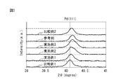
- FIG. 3 shows X-ray diffraction patterns of the exhaust gas purifying catalysts of Examples 1 to 3, Comparative Examples 1 and 2, and Reference Example.
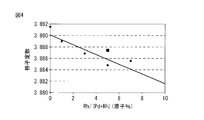
- FIG. 4 shows the relationship between Rh / (Pd + Rh) (atomic%) and the lattice constant for the exhaust gas purifying catalysts of Examples 1 to 3, Comparative Examples 1 and 2, and Reference Example.
- FIG. 1 is a schematic view showing an embodiment of a method for producing an exhaust gas purification catalyst.
- FIG. 2 is a schematic diagram showing the relationship between time t and temperature ° C. for the thermal endurance test.
- FIG. 3 shows X-ray diffraction patterns of the exhaust gas purifying catalysts of Examples 1 to 3, Comparative Examples 1 and 2, and Reference Example.
- FIG. 4 shows the relationship between Rh / (Pd + Rh) (
- FIG. 5 shows the average particle diameter (nm) calculated from the Rh / (Pd + Rh) (atomic%) and Scherrer's equations for the exhaust gas purification catalysts of Examples 1 to 3, Comparative Examples 1 and 2, and Reference Example. ).
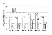
- FIG. 6 shows the HC and CO purification rates (%) at 500 ° C. for the exhaust gas purification catalysts of Examples 1 to 3, Comparative Examples 1 and 2, and Reference Example.
- FIG. 7A is a transmission electron microscope (TEM) image of the exhaust gas purifying catalyst of Comparative Example 1 after the thermal endurance test
- FIG. 7B is an example of Example 3 after the thermal endurance test. It is a TEM image of an exhaust gas purification catalyst.
- FIG. 8 is a schematic view of the exhaust gas purification system of the present invention.
- FIG. 8 is a schematic view of the exhaust gas purification system of the present invention.
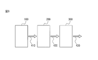
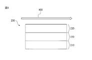
- FIG. 9 is a schematic view of the first exhaust gas purification catalyst device of the exhaust gas purification system of the present invention.
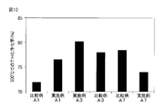
- FIG. 10 is a graph showing the THC purification rate (° C.) at 500 ° C. for the exhaust gas purification catalyst devices of Examples A1, A3, and A7 and Comparative Examples A1, A3, and A7.
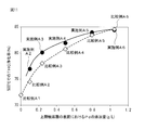
- FIG. 11 shows the amount of Pd added (g / L) on the surface of the upper catalyst layer and the THC purification rate (%) at 500 ° C. for the exhaust gas purification catalyst devices of Examples A2 to A6 and Comparative Examples A1 to A6. It is a figure which shows the relationship.
- FIG. 10 is a graph showing the THC purification rate (° C.) at 500 ° C. for the exhaust gas purification catalyst devices of Examples A1, A3, and A7 and Comparative Examples A1, A3, and A7.
- FIG. 11 shows the amount of Pd added (g / L) on the surface of the upper catalyst layer and the THC purification rate (%) at 500
- FIG. 12 is a graph showing the relationship between the exhaust gas purification catalyst devices of Examples B1, B2, and B6 and Comparative Examples B1 to B4 and B8 and the THC 50% purification temperature (° C.).
- FIG. 13 shows the amount of Pd added in the upper catalyst layer (g / L) and the THC 50% purification temperature (° C.) for the exhaust gas purification catalyst devices of Examples B2 to B5 and Comparative Examples B1 and B4 to B7. It is a figure which shows a relationship.
- FIGS. 14A and 14B are views showing TEM images taken by disassembling the upper catalyst layer of the exhaust gas purifying catalyst device of Example B2 and Comparative Example B4, respectively.
- FIG. 15 is a graph showing the oxygen storage amount (g) for the exhaust gas purifying catalyst devices of Examples C1, C3, and C6 and Comparative Examples C1 to C3.
- FIG. 16 is a graph showing the relationship between the amount of LaY-ACZ composite oxide added (g / L) and the oxygen storage amount (g) in the lower catalyst layer for the exhaust gas purification catalyst devices of Examples C2 to C5 and Comparative Example C1. It is.
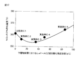
- FIG. 17 shows the relationship between the LaY-ACZ composite oxide addition amount (g / L) in the lower catalyst layer and the NOx 50% purification temperature (° C.) for the exhaust gas purification catalyst devices of Examples C2 to C5 and Comparative Example C1.
- FIG. 18 shows an electron probe microanalyzer (EPMA) image of a cross section of the exhaust gas purifying catalyst device of Example A1.
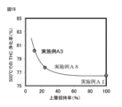
- FIG. 19 is a graph showing the relationship between the upper layer carrying rate (%) and the THC purification rate (%) at 500 ° C. for the exhaust gas purification catalyst devices of Examples A1, A3, and A8.
- EPMA electron probe microanalyzer
- the exhaust gas purifying catalyst of the present invention has composite metal fine particles containing Pd and Rh.
- the average ratio of the total number of Rh atoms to the total number of Pd and Rh atoms is 0.5 atomic% or more and 6.5 atomic% or less.
- Rh which is relatively difficult to grow
- Pd which is relatively easy to grow
- this composite metal fine particle can have the property of preventing grain growth while exhibiting the exhaust gas purifying ability inherent in Pd.
- the composite metal fine particles can modify the property that Pd originally has relatively easy to grow while exhibiting the exhaust gas purification ability that Pd originally has.
- an exhaust gas purification catalyst capable of suppressing the particle growth of fine particles.
- the state of the composite metal fine particles contained in the exhaust gas purification catalyst of the present invention may be a state in which a part thereof is oxidized depending on the conditions of temperature, humidity, and atmosphere.
- the exhaust gas purification catalyst of the present invention can suppress the particle growth of a plurality of fine particles while maintaining the exhaust gas purification ability even when the state of the composite metal fine particles is such a state.
- the composite metal fine particles contain Pd and Rh.
- the average ratio of the total number of Rh atoms to the total number of Pd and Rh atoms may be 0.5 atomic% or more, 1 atomic% or more, 1.5 atomic% or more, or 2 atomic% or more.
- the average ratio of the total number of Rh atoms to the total number of Pd and Rh atoms is 6.5 atomic% or less, 6.0 atomic% or less, 5 atomic% or less, 4.5 atomic% or less, or 4 atomic% or less. Good.
- the “composite metal fine particle” means a material in which at least two kinds of metal elements are at least partially solid-solved.
- Pd and Rh composite metal fine particles Pd and Rh are at least partially in solid solution, and in particular, Pd and Rh at least partially form a solid solution of a single crystal structure together.
- a composite metal fine particle of Pd and Rh may have not only a part in which Pd and Rh are dissolved, but also a part in which Pd and Rh are present independently.
- the exhaust gas purifying catalyst of the present invention includes a plurality of composite metal fine particles having the above average ratio (also referred to as “average ratio A”).
- the composite of the plurality of composite metal fine particles is defined as follows: When XRD analysis is performed under the condition that the X-ray wavelength is 1.5403 mm and the diffraction plane is a crystal lattice plane of Pd (111), the diffraction angle 2 ⁇ indicating the position of the diffraction peak on the diffraction plane is specified.
- the value of the theoretical lattice constant B calculated from the following formula (I) related to the Vegard law and the actually measured lattice constant C calculated from the following formula (II) related to the Bragg law and the lattice constant is, for example, 1.020 ⁇ 10 ⁇ 3 ( ⁇ ) or less, 1.000 ⁇ 10 ⁇ 3 ( ⁇ ) or less, 0.900 ⁇ 10 ⁇ 3 ( ⁇ ) or less, 0.700 ⁇ 10 ⁇ 3 ( ⁇ ) or less, 0.688 ⁇ 10 ⁇ 3 ( ⁇ ) or less, 0.600 ⁇ 10 ⁇ 3 ( ⁇ ) or less, 0.500 ⁇ 10 ⁇ 3 ( ⁇ ) or less, 0.
- the “Vegard rule” is a value between a lattice constant (also referred to as a theoretical lattice constant) of a material in which two kinds of metal elements are in solid solution with each other and a composition ratio of the two kinds of metal elements. It means the rule of thumb that there is a proportional relationship. According to Vegard's law, this proportional relationship can be expressed by the following formula (III).
- B B 1 ⁇ Pd / (Pd + Rh) + B 2 ⁇ Rh / (Pd + Rh) (III)
- B 1 is the lattice constant of the Pd single crystal
- Pd / (Pd + Rh) is the average ratio of the total number of Pd atoms to the total number of Pd and Rh atoms
- B 2 is the lattice constant of the Rh single crystal
- Rh / (Pd + Rh) is the average ratio of the total number of Rh atoms to the total number of Pd and Rh atoms.
- the lattice constant of a Pd single crystal having a crystal lattice plane with a Miller index (hkl) of (111) as a diffraction plane is 3.890105 ⁇ ; and the lattice constant of the Rh single crystal on such a diffraction plane is 3.804646 ⁇
- the above formula (III) is converted by the average ratio (A) of the total number of Rh atoms to the total number of Pd and Rh atoms, the following formula (IV) is derived.
- B 3.890105 ⁇ (1-A) + 3.804646 ⁇ A (IV)
- the above formula (IV) is equal to the above formula (I). It should be noted that in the above formula (I), the value A is converted to a decimal point instead of atomic%, and calculation is performed.
- the absolute value of the difference between the measured lattice constant value of the composite metal fine particles having a predetermined average ratio and the theoretical lattice constant value derived by substituting the predetermined average ratio into the above formula (I) is small. It should be understood that Pd and Rh are highly compounded with each other in the composite metal fine particles. Note that the above composite degree is not a scale indicating the single composite degree of the fine particles related to Pd and Rh in the exhaust gas purification catalyst, but a scale obtained by averaging the composite degree of all the fine particles related to Pd and Rh. I want you to understand.
- the high degree of composite expressed by the absolute value of the difference between the theoretical lattice constant and the actually measured lattice constant means that a large number of fine particles are composite metal fine particles, and Pd and The ratio of the part in which Rh is solid-solved is high, and the ratio of the part in which Pd and Rh are present independently is low.
- such a low degree of compositeness indicates that a small number of fine particles are composite metal fine particles, or that the composite metal fine particles themselves are not substantially formed.
- the position of the diffraction peak on the diffractive surface is not particularly limited, but may be found within a diffraction angle 2 ⁇ of 40 ° or more and 42 ° or less.
- the materials and elements constituting the exhaust gas purification catalyst, and the amount and composition ratio thereof can be determined by a general measurement method in the catalyst field.
- the exhaust gas purification catalyst may be deactivated.
- the average particle size of the plurality of composite metal fine particles may be an average particle size of more than 0 nm, 1 nm or more, or 2 nm or more, and / or 50 nm or less, 10 nm or less, 7 nm or less, 5 nm or less, or 3 nm or less.
- the diameter may be sufficient.
- composite metal fine particles having such a particle diameter as a catalyst component By using composite metal fine particles having such a particle diameter as a catalyst component, the catalytic ability can be improved.
- the carrier particles carry composite metal fine particles.
- carrier particles carrying composite metal fine particles are not particularly limited, and any metal oxide generally used as carrier particles in the technical field of exhaust gas purification catalysts can be used.
- carrier particles examples include silica (SiO 2 ), magnesia (MgO), zirconia (ZrO 2 ), ceria (CeO 2 ), alumina (Al 2 O 3 ), titania (TiO 2 ), and their Examples thereof include solid solutions and combinations thereof. Examples of these combinations include ZrO 2 —CeO 2 composite oxide carriers.
- an acidic carrier for example, silica
- compatibility with a catalytic metal that reduces NOx is good.
- Basic carriers such as magnesia have good compatibility with K and Ba that store NOx.
- Zirconia suppresses sintering of other carrier particles at a high temperature at which other carrier particles cause sintering, and combines with Rh as a catalyst metal to cause a steam reforming reaction to generate H 2.
- NOx can be reduced efficiently.
- Ceria has an OSC (Oxygen Storage Capacity) characteristic of storing oxygen in a lean atmosphere and releasing oxygen in a rich atmosphere. Therefore, it can be suitably used for a three-way catalyst or the like.
- an acid-base amphoteric carrier such as alumina has a high specific surface area, it can be used to efficiently store and reduce NOx. Titania can exert an effect of suppressing sulfur poisoning of the catalyst metal.
- the exhaust gas purification performance of the exhaust gas purification catalyst of the present invention may be improved depending on the type, composition, combination and ratio and / or amount of the selected carrier particles. I want to be.
- the amount of the composite metal fine particles supported by the carrier particles is not particularly limited, but for example, generally 0.01 parts by mass or more, 0.10 parts by mass or more with respect to 100 parts by mass of the carrier particles, or The supported amount may be 1.00 parts by mass or more and / or 5.00 parts by mass or less, 3.00 parts by mass or less, or 1.00 parts by mass or less.
- the description of the exhaust gas purification catalyst of the present invention the following description of the exhaust gas purification catalyst manufacturing method, the description of the exhaust gas purification system, and the exhaust gas purification method can be referred to in relation to each other.
- the method for producing the exhaust gas purification catalyst is not particularly limited as long as the composite metal fine particles containing Pd and Rh can be produced.
- An example of such a method may be a coprecipitation method, a reverse micelle method, or a citrate complex method.
- the coprecipitation method includes stirring and mixing a solution containing Pd ions, Rh ions, and a pH adjusting agent, thereby preparing a mixed solution.
- the method also optionally includes adding and mixing carrier particles to such a mixed solution, thereby preparing a catalyst precursor slurry. Further, the method optionally includes drying and / or calcining such catalyst precursor slurry, thereby preparing an exhaust gas purification catalyst.
- nano-sized metal fine particles have an electron energy structure different from that of macro-sized metal fine particles due to the quantum size effect, and exhibit electrical and optical characteristics depending on the particle size. Furthermore, nano-sized metal fine particles having a very large specific surface area generally have a high catalytic activity.
- Pd and Rh do not complex with each other due to factors such as repulsion of ions in solution, It is considered that Pd fine particles and Rh fine particles are separated separately.
- the time for mixing the solution containing Pd ions, Rh ions, and a pH adjusting agent is not particularly limited, but is 0.5 hours or more and 3 hours or more, and / or 6 hours or less and 24 hours or less. The time is fine.
- the solution may be mixed while heating.
- the pH of the solution is preferably basic.
- the pH of the solution may be in the range 9-12, or in the range 10-11.
- the temperature, time, and atmosphere for drying the catalyst precursor slurry are not particularly limited, but may be, for example, a range of 80 ° C. to 200 ° C., a range of 1 hour to 24 hours, and an air atmosphere.
- the temperature, time, and atmosphere for calcining the catalyst precursor slurry are not particularly limited, but may be in the range of 400 ° C. to 1000 ° C., in the range of 2 hours to 4 hours, and in the air atmosphere.
- FIG. 1 is a schematic view showing an embodiment of a method for producing an exhaust gas purification catalyst.
- Rh ions 1, Pd ions 2, and a pH adjuster 3 that also serves as a dispersant are mixed to form a composite hydroxide 4, which is dried and / or calcined.
- Composite metal fine particles 6 supported on the carrier particles 5 are generated.
- Pd ions and Rh ions are contained in a solution containing a pH adjuster.
- Examples of the raw material for Pd ions include, but are not limited to, inorganic salts of Pd, such as nitrates, phosphates, and sulfates; organic salts of Pd, such as oxalates and acetates; Halides, such as fluoride, chloride, bromide, iodide, etc .; and combinations thereof may be mentioned.
- Rh ion raw material the above description of the Pd ion raw material can be referred to.
- the concentration of Pd ions and Rh ions is not particularly limited.
- the concentration of Pd ions and Rh ions is preferably in the range of 0.01M to 0.20M.
- the molar ratio of Pd ion and Rh ion may correlate with the molar ratio of Pd and Rh in the target composite metal fine particle, for example, the molar ratio of 1:99 to 5:95 And a molar ratio of 2:98 to 4:96.
- the molar ratio of Pd ions and Rh ions may be correlated with the average ratio of the total number of Rh atoms to the total number of Pd and Rh atoms in the composite metal fine particles of the exhaust gas purification catalyst of the present invention. In this case, these molar ratios may be determined in consideration of a reduction scale of those ions, for example, a redox potential and easiness of solid solution of each element.
- the pH adjuster is not particularly limited, and a known pH adjuster can be employed.
- the pH adjuster may be, for example, tetramethylammonium hydroxide (TMAH).
- TMAH tetramethylammonium hydroxide
- the pH adjuster may have a role as a dispersion medium that suppresses aggregation of hydroxide.
- solvent is optionally included in a solution containing Pd ions, Rh ions, and a pH adjuster.
- the solvent are not particularly limited.
- solvents may be polar solvents such as water and alcohol.
- a first embodiment of an exhaust gas purification system of the present invention includes an internal combustion engine that exhausts exhaust gas, a first exhaust gas purification catalyst device that processes the exhaust gas, and the exhaust gas that is processed by the first exhaust gas purification catalyst device And a second exhaust gas purifying catalyst device for further processing.
- the first exhaust gas purification catalyst device is disposed on the base material, the lower catalyst layer disposed on the base material, the lower catalyst layer, and the exhaust gas.
- An upper catalyst layer having a surface facing the flow path, wherein the upper catalyst layer contains the Pd—Rh composite metal fine particles in an amount of 0.1 g to 1.1 g per liter of the substrate.
- the position where the concentration of the Pd—Rh composite metal fine particles is highest in the lower layer and the upper catalyst layer is the surface of the upper catalyst layer.
- the surface of the catalyst layer of the exhaust gas purification catalyst device that is, the surface facing the exhaust gas flow path, first comes into contact with high-temperature and unpurified exhaust gas, and is therefore exposed to a harsh environment.
- a harsh environment typically, the catalyst metal contained in the catalyst layer easily grows and its catalytic activity tends to decrease.
- the Pd—Rh composite metal fine particles of the exhaust gas purifying catalyst of the present invention hardly grow and show high catalytic activity even under high temperature conditions. Therefore, in order to purify the exhaust gas under a high temperature condition where diffusion control is achieved, the exhaust gas purifying catalyst of the present invention should be present at a high concentration on the surface of the upper catalyst layer having the highest contact frequency with the exhaust gas. Is preferred. Therefore, according to the first embodiment of the exhaust gas purification system of the present invention, it is possible to achieve a higher exhaust gas purification ability than conventional under high temperature conditions.
- the rate of the catalytic reaction is limited by the rate at which the reaction substrate reaches the catalyst (diffusion rate) and the rate at which the catalyst catalyzes the chemical reaction of the reaction substrate (reaction rate).
- the rate limiting means a state in which the above diffusion rate substantially corresponds to the rate of the catalytic reaction under the condition where the above reaction rate is sufficiently high (for example, high temperature condition).
- the amount of the composite metal fine particles on the surface of the upper catalyst layer of the first exhaust gas purification apparatus is 0.1 g or more, 0.2 g or more, 0.3 g or more, or 0. 4 g or more and / or 1.1 g or less, 1.0 g or less, 0.9 g or less, or 0.8 g or less.
- both the Pd metal fine particles and the Pd—Rh composite metal fine particles exhibit higher catalytic activity as the amount thereof increases. Therefore, when the amount is excessive, these Pd metal fine particles and Pd—Rh The difference in catalytic activity of the composite metal fine particles is substantially eliminated.
- the amount of the Pd metal fine particles is small, the catalytic activity tends to decrease, whereas when the amount of the Pd—Rh composite metal fine particles is small, the catalytic activity hardly decreases, as a result, The smaller the amount of Pd metal fine particles or Pd—Rh composite metal fine particles, the greater the difference in catalytic activity between them.
- the state where the catalyst metal is supported on the surface of the upper catalyst layer may be defined by the upper layer support rate.
- the catalyst metal is “supported on the surface of the upper catalyst layer” means that the upper layer support ratio is 40% or less, 38% or less, 36% or less, 35% or less, 34% or less. 32% or less, 30% or less, 28% or less, 26% or less, 25% or less, 23% or less, 21% or less, or 20% or less, and / or the upper layer support The rate is over 0%, 1% or more, 3% or more, 5% or more, 7% or more, 9% or more, 10% or more, 13% or more, 15% or more, 17% or more, or 19% or more And may be defined.
- the configuration is the same as that of the first embodiment except for the first exhaust gas purification catalyst device.
- the first exhaust gas purification catalyst device includes a base material, a lower catalyst layer disposed on the base material, and a lower catalyst layer. And an upper catalyst layer having a surface facing the exhaust gas flow path, and the upper catalyst layer contains 0.1 g or more of the Pd—Rh composite metal fine particles per liter of the base material. In the upper catalyst layer, the concentration of the Pd—Rh composite metal fine particles is substantially uniform in the thickness direction.
- the amount of the composite metal fine particles contained in the upper catalyst layer of the first exhaust gas purification apparatus is 0.1 g or more, 0.2 g or more, 0.3 g or more, or 0. 4 g or more and / or 1.2 g or less, 1.1 g or less, 1.0 g or less, 0.9 g or less, or 0.8 g or less.
- the logic relating to the amount refer to the description of the first embodiment.
- the configuration is the same as that of the first embodiment except for the first exhaust gas purification catalyst device.
- the first exhaust gas purifying catalyst device includes a base material, a lower catalyst layer disposed on the base material, and a lower catalyst layer. And an upper catalyst layer having a surface facing the flow path of the exhaust gas, and the lower catalyst layer contains ceria-based carrier particles carrying the Pd—Rh composite metal fine particles. The concentration of the Pd—Rh composite metal fine particles is approximately uniform in the thickness direction in the lower catalyst layer.
- the present inventors have found that this problem can be solved by improving the catalytic activity of such a catalyst component and reducing the amount thereof. Specifically, the present inventors have higher ceria-based carrier particles carrying Pd—Rh composite metal fine particles as a catalyst component compared to conventional ceria-based carrier particles carrying a catalytic metal. Found to show OSC.
- the reason for exhibiting high OSC is that the number of active sites of Pd in the Pd—Rh composite metal fine particles having a sintering suppressing effect is larger than the number of active points of the Pd metal fine particles, Further, there is an oxygen storage active point at the interface portion between the Pd metal fine particles and ceria, and the number of oxygen storage active points at the interface portion between Pd and ceria in the Pd—Rh composite metal fine particles is Pd metal fine particles. This is considered to be because the number of active sites of oxygen storage at the interface portion between C and Ceria is larger.
- the amount of the ceria-based carrier particles supporting the exhaust gas purification catalyst of the present invention contained in the lower catalyst layer of the first exhaust gas purification device is more than 0.0 g per liter of the substrate volume, 5.0 g or more, 10.0 g or more, 15.0 g or more, 20.0 g or more, or 25.0 g or more, and / or 75.0 g or less, 73.0 g or less, 70.0 g or less, 65.0 g or less , 60 g or less, or 55.0 g or less.
- the amount of ceria-based carrier particles carrying the exhaust gas purifying catalyst of the present invention is large, the oxygen storage amount and NOx adsorption ability can be increased. Further, when the amount is small, an improved oxygen storage capacity can be exhibited as compared with the ceria-based support particles on which the conventional catalytic metal is supported.
- the base material has an upstream end that is an inlet portion into which exhaust gas enters and a downstream end that is an outlet portion from which exhaust gas exits
- the lower catalyst layer is From the upstream end to the downstream end of the substrate, 80% or less, 75% or less, 70% or less, 65% or less, or 60% or less, and / or 10% or more, 15% or more, 20% of the total length of the substrate
- the length is 25% or more, 30% or more, 35% or more, 40% or more, 45% or more, or 50% or more.
- the present inventors can improve the oxygen storage amount of the catalyst component without changing the amount of the catalyst component by changing the position where the catalyst layer containing the catalyst component is formed, I found more.
- the oxygen storage amount of the catalyst component is improved by forming the lower catalyst layer from the upstream end to the downstream end of the substrate with a length of 80% or less of the total length of the substrate. It becomes possible to do.
- FIG. 8 is a schematic view of the exhaust gas purification system of the present invention.
- the internal combustion engine 100 that discharges the exhaust gas 410, the first exhaust gas purification catalyst device 200 that processes the exhaust gas 410, and the processed exhaust gas 420 are further processed and further processed.
- the second exhaust gas purification catalyst devices 300 discharged as the exhaust gas 430 are arranged in this order.
- FIG. 9 is a schematic view of the first exhaust gas purification catalyst device of the exhaust gas purification system of the present invention.
- the first exhaust gas purification catalyst device 200 of FIG. 9 includes a substrate 210, a lower catalyst layer 220, and an upper catalyst layer 230, and the exhaust gas 400 passes above the upper catalyst layer 230.
- Examples of internal combustion engines include, but are not limited to, gasoline engines, diesel engines, and lean burn engines.
- the first exhaust gas purification catalyst device is also called a start converter (SC) type catalyst device, and purifies exhaust gas discharged from the internal combustion engine.
- the first exhaust gas purification catalyst device comprises a base material, a lower catalyst layer disposed on the base material, a surface disposed on the lower catalyst layer and facing the exhaust gas flow path. And an upper catalyst layer.
- the substrate has a gas flow path (also referred to as a hole) through which exhaust gas passes.
- the substrate structure may be, for example, a honeycomb structure, a foam structure, or a plate structure.
- Examples of the material of the base material are not particularly limited, and may be made of a cordierite, a ceramic such as SiC, or a metal.
- the catalyst component of the lower catalyst layer is not particularly limited, but may include a catalyst metal, carrier particles, a sintering inhibitor, and a binder.
- the catalyst component of the lower catalyst layer includes ceria-based support particles in addition to the above-described catalyst component, and the ceria-based support particles include the Pd—Rh composite metal of the exhaust gas purification catalyst of the present invention. Fine particles are supported.
- catalyst metals examples include platinum group metals such as Pt, Pd, Rh, combinations thereof, and solid solutions thereof.
- the catalyst metal may contain Pd—Rh composite metal fine particles contained in the exhaust gas purification catalyst of the present invention.
- Carrier Particles for examples of carrier particles, see the item “Carrier Particles” in the exhaust gas purification catalyst of the present invention described above.
- ceria-based carrier particles are not particularly limited, but may be ceria alone or complex oxide carrier particles containing ceria and one or more other oxides.
- “Composite oxide” means a material in which at least two kinds of metal oxides are at least partially dissolved.
- composite oxides containing ceria and zirconia are those in which ceria and zirconia are at least partially in solid solution, in particular ceria and zirconia are at least partially oxidized in a single crystal structure. It means that things are formed together.
- a composite oxide containing ceria and zirconia may include not only a portion in which ceria and zirconia are solid-solved but also a portion in which ceria and zirconia are present alone. Good.
- ceria-based carrier particles are not particularly limited, but may be ceria (CeO 2 ) -zirconia (ZrO 2 ) composite oxide or alumina (Al 2 O 3 ) -ceria-zirconia composite oxide.
- rare earth elements such as yttrium (Y), lanthanum (La), neodymium (Nd), and / or praseodymium (Pr) may be added to these composite oxides. May take the form of its oxide.
- the amount of the Pd—Rh composite metal fine particles of the exhaust gas purifying catalyst of the present invention carried by the ceria-based carrier particles is 0.01 parts by mass or more and 0.10 parts by mass based on 100 parts by mass of the ceria-based carrier particles. Or more, 0.20 parts by mass or more, 0.30 parts by mass or more, 0.50 parts by mass or more, 0.70 parts by mass or more, or 1.00 parts by mass or more, and / or 5.00 parts by mass or less, It may be 3.00 parts by mass or less, or 1.00 parts by mass or less.
- the sintering inhibitor can suppress sintering between carrier particles, sintering between catalyst metals, and burying of the catalyst metal in the carrier.
- the example of the binder is not particularly limited, but may be an alumina binder.
- the catalyst component of the upper catalyst layer is not particularly limited, but may include a catalyst metal, carrier particles, a sintering inhibitor, and a binder.
- the catalyst component of the upper catalyst layer includes Pd—Rh composite metal fine particles of the exhaust gas purification catalyst of the present invention in addition to the above catalyst component.
- the carrier particles, the sintering inhibitor, and the binder refer to the description regarding the lower catalyst layer, and for the Pd—Rh composite metal fine particles, the description regarding the exhaust gas purification catalyst of the present invention described above. Please refer.
- the second exhaust gas purification catalyst device further processes the exhaust gas purified by the first exhaust gas purification catalyst device.
- the second exhaust gas purification catalyst device is also called an underfloor (UF) type catalyst device, for example, a three-way (TW) catalyst device, a NOx occlusion reduction (NSR) type catalyst device, or a selective catalyst reduction (SCR) type catalyst device. It can be a device.
- the method for producing the first exhaust gas purification catalyst device includes at least the following steps: Applying a slurry for the lower catalyst layer to the substrate to form a slurry layer for the lower catalyst layer, drying and firing the slurry layer for the lower catalyst layer, and forming a lower catalyst layer; and The upper catalyst layer slurry is further applied to the lower catalyst layer formed on the surface of the material to form an upper catalyst layer slurry layer, and the upper catalyst layer slurry layer is dried and fired, Forming the upper catalyst layer;
- the method for manufacturing the first exhaust gas purification catalyst device according to the first embodiment described above further includes the following steps and features: Impregnating and supporting a solution containing Pd ions and Rh ions on the surface of the upper catalyst layer, and drying and firing the upper catalyst layer; The ratio of the total moles of Rh ions to the total moles of Pd ions and Rh ions in the solution is 0.5 or more and 6.5 or less, and the amount of Pd ions and Rh ions in the solution is the base material.
- the amount should be such that
- the first exhaust gas purification catalyst device in the first embodiment of the above exhaust gas purification system can be manufactured.
- the above upper layer supporting rate can be changed depending on the pH value of the solution containing the above Pd ions and Rh ions. Adjustment of pH is easy for those skilled in the art with reference to this specification.
- the upper catalyst layer slurry includes carrier particles on which the Pd—Rh composite metal fine particles are supported,
- the amount of the Pd—Rh composite metal fine particles carried on the carrier particles is 0.1 g or more, 0.2 g or more, 0.3 g or more, or 0.4 g or more per liter of the substrate volume, and / Or 1.2 g or less, 1.1 g or less, 1.0 g or less, 0.9 g or less, or 0.8 g or less.
- the first exhaust gas purification catalyst device in the second embodiment of the exhaust gas purification system can be manufactured.
- the method for producing the first exhaust gas purification catalyst device according to the second embodiment described above further includes the following features:
- the lower catalyst layer slurry includes carrier particles on which the Pd—Rh composite metal fine particles are supported;
- the amount of the carrier particles on which the Pd—Rh composite metal fine particles are supported is more than 0.0 g, 5.0 g or more, 10.0 g or more, 15.0 g or more, 20.0 g or more per liter of the base material, Alternatively, the amount is 25.0 g or more and / or 75.0 g or less, 73.0 g or less, 70.0 g or less, 65.0 g or less, 60 g or less, or 55.0 g or less.
- the first exhaust gas purification catalyst device in the third embodiment of the above exhaust gas purification system can be manufactured.
- the step of forming the lower catalyst layer may include an operation of preparing the lower catalyst layer slurry.
- the lower catalyst layer slurry may contain a solvent and a binder in addition to the materials contained in the lower catalyst layer of the exhaust gas purification catalyst device of the present invention.
- Examples of the solvent are not particularly limited, but may be water or ion exchange water, for example.
- the example of a binder is not specifically limited, An alumina binder may be sufficient.
- An example of a method for applying the lower catalyst layer slurry is not particularly limited, but may be a wash coat method.
- the temperature, time, and atmosphere for drying the lower catalyst layer slurry layer are not particularly limited.
- the drying temperature may be, for example, 70 ° C or higher, 75 ° C or higher, 80 ° C or higher, or 90 ° C or higher, and may be 150 ° C or lower, 140 ° C or lower, 130 ° C or lower, or 120 ° C or lower.
- the drying time may be, for example, 1 hour or more, 2 hours or more, 3 hours or more, or 4 hours or more, and may be 12 hours or less, 10 hours or less, 8 hours or less, or 6 hours or less.
- the atmosphere to be dried may be an air atmosphere, for example.
- the temperature, time, and atmosphere for firing the lower catalyst layer slurry layer are not particularly limited.
- the baking temperature may be, for example, 300 ° C. or higher, 400 ° C. or higher, or 500 ° C. or higher, and may be 1000 ° C. or lower, 900 ° C. or lower, 800 ° C. or lower, or 700 ° C. or lower.
- the firing time may be, for example, 1 hour or more, 2 hours or more, 3 hours or more, or 4 hours or more, and may be 12 hours or less, 10 hours or less, 8 hours or less, or 6 hours or less.
- the firing atmosphere may be, for example, an air atmosphere.
- the step of forming the upper catalyst layer may include an operation of preparing an upper catalyst layer slurry.
- the description of the preparation and coating of the lower catalyst layer slurry and the drying of the layer can be referred to.
- the step of supporting the Pd—Rh composite metal fine particles on the surface of the upper catalyst layer may include an operation of preparing a solution containing Pd ions and Rh ions.
- Method for preparing a solution containing Pd ions and Rh ions see the item “Method for producing exhaust gas purification catalyst” above.
- This solution is applied to the surface of the upper catalyst layer, dried and fired.
- conditions for drying and firing conditions for drying and firing the lower catalyst layer slurry layer may be employed.
- the method of the present invention for purifying exhaust gas comprises contacting the exhaust gas containing HC, CO, and NOx with the above-described exhaust gas purification catalyst of the present invention in a stoichiometric atmosphere, thereby oxidizing HC and CO, and NOx is reduced and purified.
- the method of the present invention is preferably applied to an internal combustion engine operating in a stoichiometric atmosphere.
- HC and CO as reducing agents and NOx as oxidizing agents react at a theoretical equivalent ratio, and these can be converted into H 2 O, CO 2 , and N 2 .
- the method of bringing the exhaust gas into contact with the exhaust gas purification catalyst of the present invention in a stoichiometric atmosphere may be an optional method.
- Example 3 Coprecipitation method >> ⁇ Mixed solution preparation process> 31.25 g of Pd nitrate solution (5 g in terms of mass of Pd, Cataler Co., Ltd.) was put into a beaker. Further, 9.28 g of an Rh nitrate solution (0.26 g in terms of Rh mass, Cataler Co., Ltd.) was charged into the beaker. The mixed solution prepared by mixing these two types of metal nitrate solutions was further stirred for 1 hour or more. Next, a 15% by mass TMAH solution (Wako Pure Chemical Industries, Ltd.) was added to the mixed solution so that the pH of the mixed solution was 10 or more. Thereafter, the concentration of the mixed solution was adjusted with pure water so that the total metal concentration was 3% by mass.
- TMAH solution Wi-TMAH solution
- the fired product was pressed at 1 ton / cm 2 to form a solid, and the solid was placed in a sieve and struck with a mortar to obtain a pellet shape having a diameter of 1.0 mm to 1.7 mm.
- An exhaust gas purification catalyst was obtained.
- Comparative Example 1 Examples 1 and 2, and Reference Example: Coprecipitation Method >> Comparative examples except that the mixed solution was prepared so that the molar ratios of Pd and Rh in the mixed solution were 100: 0, 99: 1, 97: 3, and 93: 7 in the mixed solution preparation step. 1, Exhaust gas purification catalysts of Examples 1 and 2 and Reference Example were obtained in the same manner as Example 3.
- Comparative Example 2 Co-impregnation method >> In the mixed solution preparation step, the exhaust gas purification catalyst of Comparative Example 2 was obtained in the same manner as Example 3 except that the TMAH solution was not used.
- the steps of the thermal endurance test are as follows (1) to (5): (1) The sample was placed in an N 2 atmosphere with a gas flow rate of 10 L / min, and the sample was heated from room temperature to 1050 ° C .; (2) The atmosphere was changed to the mixed gas R, and the mixed gas R was exposed to the sample at a flow rate of 10 L / min for 2 minutes; (3) The atmosphere was changed to the mixed gas L, and the mixed gas L was exposed to the sample at a flow rate of 10 L / min for 2 minutes; (4) Thereafter, the steps (2) and (3) were repeated alternately, and the number of steps (2) and (3) was 151 in total. That is, the steps (2) and (3) were performed for a total time of 302 minutes. This operation was completed in the step (2). ; (5) Then, switch to N 2 atmosphere and cooled the temperature of the sample from 1050 ° C. to room temperature.
- the components constituting the mixed gas R (rich) are CO: 1%, H 2 O: 3%, and N 2 balance, and the components constituting the mixed gas L (lean) are O 2 : 5%. , H 2 O: 3%, and N 2 balance.
- FIG. 2 shows the relationship between the time t and the temperature ° C. for the thermal endurance test.
- Measurement mode is FT (Fixed Time) mode
- X-ray source is CuK ⁇ ( ⁇ : 1.5403 mm); step width is 0.01 deg; counting time is 3.0 sec; divergence slit (DS) is 2/3 deg; SS) is 2/3 deg; light receiving slit (RS) is 0.5 mm; tube voltage is 50 kV; and tube current is 300 mA.
- FIG. 3 is a diagram showing X-ray diffraction patterns of the exhaust gas purifying catalysts of Examples 1 to 3, Comparative Examples 1 and 2, and Reference Example.
- FIG. 3 when the crystal lattice plane of the Pd (111) single crystal is used as a diffraction plane, a vertical line indicating the peak position of this diffraction plane is shown.
- the peak position of Comparative Example 1 containing only Pd fine particles is equal to the peak position of the diffraction surface.
- the peak positions of Examples 1 to 3, Comparative Example 2, and Reference Example are shifted to the high angle side. This indicates that Pd and Rh are contained in the exhaust gas purification catalyst of these examples.
- the composite degrees of the exhaust gas purifying catalysts of Examples 1 to 3, Comparative Example 2, and Reference Example are determined in consideration of not only the peak position but also the composition ratio.
- Example 1 As described above, the smaller the absolute value of the difference between the theoretical lattice constant B and the measured lattice constant C is, the higher the degree that Pd and Rh are dissolved in each other. Therefore, it can be seen from Table 2 that the composite degree of Example 1 (0.261 ⁇ 10 ⁇ 3 ) is the highest and the composite degree of Comparative Example 2 (1.578 ⁇ 10 ⁇ 3 ) is the lowest. That is, in Example 1, many composite metal fine particles may be formed with high solid solubility.
- Comparative Example 2 there is a high possibility that a plurality of fine particles are separately formed as Pd fine particles and Rh fine particles, and even if composite metal fine particles are formed,
- the ratio of the part in which Pd and Rh are solid-solved may be low, and the ratio of the part in which Pd and Rh are each present alone may be high.
- Each plot point in FIG. 4 corresponds to the exhaust gas purification catalyst in each of the above examples, and the hatched line indicates the above formula (I). That is, the closer the plot point is to the oblique line, the higher the composite degree of the fine particles in the example corresponding to the plot point.
- the production method the molar ratio of Pd and Rh contained therein (also referred to as “Pd: Rh (molar ratio)”), Rh / (Pd + Rh) (atomic%)
- BC) calculated from the Scherrer equation are as follows: Table 3 shows. Further, regarding the exhaust gas purifying catalyst of each example, the relationship between Rh / (Pd + Rh) (atomic%) and the average particle diameter (nm) of the fine particles is shown in FIG.
- FIG. 5 shows that in the region of 52.0 nm or less which is the average particle size of Example 1, that is, in the region of 0.5 atomic% or more and 6.5 atomic% or less in Rh / (Pd + Rh). It is understood that is suppressed.
- the exhaust gas purifying ability was evaluated based on the amounts of HC and CO purified by each catalyst when the exhaust gas purifying catalysts of Examples 1 to 3, Comparative Examples 1 and 2 and Reference Example were exposed to a test gas (that is, H 2 O and CO 2 increments) were measured by FT-IR analyzer.
- components constituting the test gas CO: 0.65vol%, CO 2 : 10.00vol%, C 3 H 6: 3000ppmC (1000ppm), NO: 1500ppm, O 2: 0.70vol%, H 2 O : 3.00 vol% and N 2 balance.
- FIG. 6 shows the HC and CO purification rates (%) at 500 ° C. for the exhaust gas purification catalysts of Examples 1 to 3, Comparative Examples 1 and 2, and Reference Example.
- FIG. 6 shows that the HC purification rates of Examples 1 to 3 and the reference example are higher than the HC purification rates of Comparative Examples 1 and 2. The same is true for the CO purification rate.
- Example 3 when the purification rate of HC of Example 3 and Comparative Example 2 in which the value of Rh / (Pd + Rh) is 5, the value of Example 3 is the same as that of Comparative Example 2. Higher than the value. This is considered because the average particle diameter of the composite metal fine particles contained in the exhaust gas purification catalyst of Example 3 is smaller than that of Comparative Example 2. The same is true for the CO purification rate. Note that, in general, when the particle size of the fine particles is small, the number of active sites increases as the specific surface area increases, thereby improving the exhaust gas purification ability.
- FIG. 7A is a transmission electron microscope (TEM) image of the exhaust gas purification catalyst of Comparative Example 1 after the thermal endurance test
- FIG. 7B is an illustration of the exhaust gas purification catalyst of Example 3 after the thermal endurance test. It is a TEM image.
- the particle diameters of the measurement points 1 of Comparative Example 1 and Example 3 in Table 5 are the particle diameters of the fine particles measured in FIGS. 7A and 7B, respectively.
- the average particle size of Comparative Example 1 and Example 3 before the durability test is about 3 nm. Further, from Table 5, it is understood that the average particle diameter of Comparative Example 1 after the durability test is 55.1875 nm, and the grain growth rate is 1768.8% compared to that before the durability test. The Furthermore, from Table 5, it is understood that the average particle diameter of Example 3 after the durability test is 47.7875 nm, and the grain growth rate is 1592.9% compared with that before the durability test. The That is, the grain growth rate of Example 3 is smaller than that of Comparative Example 1.
- Rh which is thermally stable and relatively difficult to grow, is compounded with Pd, which is relatively easy to grow, so that It is suggested that grain growth was suppressed.
- Examples A1 to A8 and Comparative Examples A1 to A7 >>
- the exhaust gas purifying catalyst devices of Examples A1 to A8 and Comparative Examples A1 to A7, in which the base material, the lower catalyst layer, and the upper catalyst layer are formed in this order, are manufactured and evaluated. Below, the optimum position where the composite metal fine particles are applied and the amount thereof are examined.
- the unit “g / L” means the mass (g) of the material carried per 1 L of the base material.
- Rg metal fine particles of 0.2 g / L means that the amount of Rh metal fine particles per liter of the substrate is 0.2 g.
- ⁇ Comparative Example A1 >> ⁇ Preparation of lower catalyst layer> Carrier particles 1, carrier particles 2, barium sulfate, and Al 2 O 3 -based binder were added to stirred distilled water, thereby preparing a lower catalyst layer slurry. Next, the slurry was poured into a cordierite honeycomb substrate (material 5), and a blower was applied to the slurry to blow off excess slurry, thereby coating the lower layer catalyst layer slurry on the substrate. The coating amount was adjusted to be 1: 40 g carrier particles, 2: 45 g carrier particles, 5 g barium sulfate, and 5 g Al 2 O 3 binder per 1 L of cordierite honeycomb substrate.
- the base material coated with the lower catalyst layer slurry was dried at 120 ° C. for 2 hours and calcined at 500 ° C. for 2 hours.
- a cordierite honeycomb substrate on which the lower catalyst layer was formed was prepared.
- Rh-supported carrier particles 3 were prepared by impregnating the carrier particles 3 with a Rh nitrate solution.
- the slurry is poured into a cordierite honeycomb substrate on which the lower catalyst layer is formed, and a blower is applied to the slurry to blow off excess slurry, whereby the upper catalyst layer is formed on the substrate.
- the slurry was coated. The coating amount was adjusted so that carrier particle 1:63 g, carrier particle 2:38 g, and Rh carrier particle 3:72 g (Rh 0.2 g) per 1 L of cordierite honeycomb substrate.
- the substrate coated with the upper catalyst layer slurry was dried at 120 ° C. for 2 hours and calcined at 500 ° C. for 2 hours.
- a cordierite honeycomb substrate on which the upper catalyst layer and the lower catalyst layer were formed that is, an exhaust gas purification catalyst device of Comparative Example A1, was prepared.
- Example A1 The exhaust gas purification catalyst device of Example A1 was prepared in the same manner as in Comparative Example A1, except that the carrier particles 2 were impregnated and calcined in “Preparation of upper catalyst layer” in Comparative Example A1. .
- Examples A2 to A6 The exhaust gas purification catalyst devices of Examples A2 to A6 were prepared by impregnating and firing the Pd—Rh mixed solution on the surface of the upper catalyst layer of the exhaust gas purification catalyst device of Comparative Example A1. Specifically, the Pd—Rh mixed solution was impregnated, and the exhaust gas purifying catalyst device of Comparative Example A1 was dried at 120 ° C. for 2 hours and calcined at 500 ° C. for 2 hours.
- Comparative Examples A2 to A6 were prepared by impregnating the surface of the upper catalyst layer of the exhaust gas purification catalyst device of Comparative Example A1 with a Pd nitrate solution. Specifically, the exhaust gas purification catalyst device of Comparative Example A1 was further impregnated with a Pd nitrate solution, dried at 120 ° C. for 2 hours, and calcined at 500 ° C. for 2 hours.
- Comparative Example A7 The exhaust gas purification catalyst device of Comparative Example A7 was prepared by impregnating and baking the surface of the upper catalyst layer of the exhaust gas purification catalyst device of Comparative Example A1 with a Pd nitrate solution and a Rh nitrate solution. Specifically, the exhaust gas purification catalyst device of Comparative Example A1 is further impregnated with a Pd nitrate solution, dried at 120 ° C. for 2 hours, and the surface of the upper catalyst layer of the exhaust gas purification catalyst device is further impregnated with an Rh nitrate solution. This was dried at 120 ° C. for 2 hours and calcined at 500 ° C. for 2 hours.
- Example A7 An exhaust gas purification catalyst device of Example A7 was prepared in the same manner as in Comparative Example A1, except that the carrier particles 2 were impregnated with “Preparation of lower catalyst layer” in Comparative Example A1.
- Example A8 The exhaust gas purification catalyst device of Example A8 was prepared by impregnating and baking the Pd—Rh mixed solution on the surface of the upper catalyst layer of the exhaust gas purification catalyst device of Comparative Example A1. Specifically, a Pd—Rh mixed solution with adjusted pH was used. By adjusting the pH of the mixed solution, the adsorptivity of the Pd—Rh composite hydroxide or the like is lowered, and as a result, the depth of supporting the composite hydroxide can be made deeper than that of Example A3. it can. In addition, this depth means the depth to the lamination direction from the surface of an upper catalyst layer.
- Tables 6 to 8 below show the configurations of the exhaust gas purifying catalyst devices of Examples A1 to A8 and Comparative Examples A1 to A7.
- the total amount of Rh is adjusted to be 0.2 g / L.
- Rh (g / L) of 0.200 or 0.187 is supported on the support particles 3 instead of the support particles 2. Please keep in mind.
- single particle means a state in which a single elemental metal fine particle of Pd or Rh is supported on a carrier particle
- composite fine particle means that a composite metal fine particle of Pd and Rh is a carrier particle.
- physical mixing means a state in which Pd single element metal fine particles and Rh single element metal fine particles are mixed.
- FIG. 10 is a graph showing the THC purification rate (%) at 500 ° C. for the exhaust gas purification catalyst devices of Examples A1, A3, and A7 and Comparative Examples A1, A3, and A7.
- FIG. 10 shows that the THC purification rate at 500 ° C. of Example A7 containing Pd—Rh composite metal fine particles in the lower catalyst layer is higher than that of Comparative Example A1 not containing the composite metal fine particles. . This indicates that the exhaust gas purifying catalyst device of Example A7 including the Pd—Rh composite metal fine particles which are difficult to grow grains efficiently purified THC.
- Example A7 includes Pd—Rh composite metal fine particles in the lower catalyst layer
- Example A1 includes this in the upper catalyst layer
- Example A3 includes this on the surface of the upper catalyst layer.
- Example A3 contains Pd—Rh composite metal fine particles on the surface of the upper catalyst layer
- Comparative Example A3 contains Pd metal fine particles in the same layer
- Comparative Example A7 contains Pd metal fine particles in the same layer.
- Rh metal fine particles are included in a mixed state.
- FIG. 11 shows the relationship between the amount of Pd added (g / L) at the outermost surface and the THC purification rate (%) at 500 ° C. for the exhaust gas purification catalyst devices of Examples A2 to A6 and Comparative Examples A1 to A6.
- FIG. 11 shows the relationship between the amount of Pd added (g / L) at the outermost surface and the THC purification rate (%) at 500 ° C. for the exhaust gas purification catalyst devices of Examples A2 to A6 and Comparative Examples A1 to A6.
- Example A2 to A6 containing Pd—Rh composite metal fine particles on the surface of the upper catalyst layer are as follows. It can be seen that it is higher than those of Comparative Examples A2 to A6 that contain it. This indicates that the Pd—Rh composite metal fine particles which are difficult to grow at high temperatures have higher catalytic activity than the Pd metal fine particles.
- the amounts of Pd metal in Examples A2 to A6 are the same as those in Comparative Examples A2 to A6, respectively.
- the THC purification rate of Example A6 in which the amount of Pd metal is 1.050 g / L is substantially the same as that of Comparative Example A6 in which the amount of Pd metal is the same amount.
- the Pd—Rh composite metal fine particles that are difficult to grow are contained in the surface of the upper catalyst layer that frequently contacts with the exhaust gas at a rate of more than 0 g / L and 1.050 g / L. It is understood that a high THC purification rate is achieved.
- FIG. 18 shows an electron probe microanalyzer (EPMA) image of a cross section of the exhaust gas purifying catalyst device of Example A1. From FIG. 18, it can be seen that Pd (the white spot portion of the upper catalyst layer in FIG. 18) is distributed on the surface of the upper catalyst layer, and that there is a thickness of the layer where Pd is distributed.
- EPMA electron probe microanalyzer
- FIG. 19 is a graph showing the relationship between the upper layer carrying rate (%) and the THC purification rate (%) at 500 ° C. for the exhaust gas purification catalyst devices of Examples A1, A3, and A8.
- Examples B1 to B6 and Comparative Examples B1 to B8 >>
- the exhaust gas purification catalyst devices of Examples B1 to B6 and Comparative Examples B1 to B8, in which the base material, the lower catalyst layer, and the upper catalyst layer are formed in this order, are manufactured and evaluated. We are investigating the optimal position and amount of the composite metal fine particles to be applied under the conditions.
- ⁇ Preparation ⁇ ⁇ Support particles 1 (La-Al composite oxide) Carrier particles 1 were prepared in the same manner as those used in the “Preparation” section of Examples A1 to A8 and Comparative Examples A1 to A7.
- ⁇ Support particles 2 (LaY-ACZ composite oxide) Carrier particles 2 were prepared in the same manner as those used in the “Preparation” section of Examples A1 to A8 and Comparative Examples A1 to A7.
- ⁇ Support particles 3 (NdLaY-ACZ composite oxide) Carrier particles 3 were prepared in the same manner as those used in the “Preparation” section of Examples A1 to A8 and Comparative Examples A1 to A7.
- Pd—Rh mixed solution Pd—Rh mixed solutions were prepared in the same manner as those used in the “Preparation” section of Examples A1 to A8 and Comparative Examples A1 to A7.
- Base material The same base material as that used in the item “Preparation” in Examples A1 to A8 and Comparative Examples A1 to A7 was used.
- ⁇ Comparative Example B1 >> ⁇ Preparation of lower catalyst layer> Carrier particles 1, carrier particles 2, barium sulfate, and Al 2 O 3 -based binder were added to stirred distilled water, thereby preparing a lower catalyst layer slurry. Next, the slurry was poured into a cordierite honeycomb substrate (material 5), and a blower was applied to the slurry to blow off excess slurry, thereby coating the lower layer catalyst layer slurry on the substrate. The coating amount was adjusted to be 1: 40 g carrier particles, 2: 45 g carrier particles, 5 g barium sulfate, and 5 g Al 2 O 3 binder per 1 L of cordierite honeycomb substrate.
- the base material coated with the lower catalyst layer slurry was dried at 120 ° C. for 2 hours and calcined at 500 ° C. for 2 hours.
- a cordierite honeycomb substrate on which the lower catalyst layer was formed was prepared.
- Rh-supported carrier particles 3 were prepared by impregnating the carrier particles 3 with a Rh nitrate solution.
- the slurry is poured into a cordierite honeycomb substrate on which the lower catalyst layer is formed, and a blower is applied to the slurry to blow off excess slurry, whereby the upper catalyst layer is formed on the substrate.
- the slurry was coated. The coating amount was adjusted so that carrier particle 1:63 g, carrier particle 2:38 g, and Rh-supported carrier particle 3:72 g (Rh: 0.2 g) per 1 L of cordierite honeycomb substrate.
- the substrate coated with the upper catalyst layer slurry was dried at 120 ° C. for 2 hours and calcined at 500 ° C. for 2 hours.
- a cordierite honeycomb substrate on which the upper catalyst layer and the lower catalyst layer were formed that is, the exhaust gas purification catalyst device of Comparative Example B1, was prepared.
- Example B1 >> In Comparative Example B1, “Preparation of lower catalyst layer”, Pd—Rh mixed solution was impregnated and fired in support particles 2, and in “Preparation of upper catalyst layer”, the amount of catalyst metal Rh of support particles 3 was changed. Except that, the exhaust gas purifying catalyst device of Example B1 was prepared in the same manner as in Comparative Example B1.
- Comparative Example B2 An exhaust gas purifying catalyst device of Comparative Example B2 was prepared in the same manner as Comparative Example B1, except that the carrier particles 2 were impregnated and calcined in “Preparation of Lower Catalyst Layer” of Comparative Example B1.
- the amount of Pd in the Pd nitrate solution is 0.100 (g / L).
- Examples B2 to B5 >> In Comparative Example B1 “Preparation of the upper catalyst layer”, the support particles 2 were impregnated and calcined with the mixed solution of Pd—Rh, and in “Preparation of the upper catalyst layer”, the amount of the catalyst metal Rh of the support particles 3 was changed. Except for this, the exhaust gas purifying catalyst devices of Examples B2 to B5 were prepared in the same manner as in Comparative Example B1.
- Comparative Example B3 >> In “Preparation of upper catalyst layer” in Comparative Example B1, the support particle 2 was impregnated and calcined in “preparation of upper catalyst layer”. In “Preparation of upper catalyst layer”, another carrier particle 2 was impregnated and calcined with Rh nitrate.
- the exhaust gas purifying catalyst device of Comparative Example B3 was prepared in the same manner as Comparative Example B1, except that the amount of the catalytic metal Rh of the carrier particles 3 was changed in “Preparation of upper catalyst layer”.
- Comparative Examples B4 to B7 >> Exhaust gas purification catalyst devices of Comparative Examples B4 to B7 were prepared in the same manner as in Comparative Example B1, except that the carrier particles 2 were impregnated and calcined in “Preparation of upper catalyst layer” of Comparative Example B1. .
- Example B6 >> In Comparative Example B1 “Preparation of upper catalyst layer”, the amount of catalyst metal Rh of the carrier particles 3 was changed to prepare an exhaust gas purification catalyst device, and the surface of the upper catalyst layer of this exhaust gas purification catalyst device was Pd ⁇ Exhaust gas purification catalyst device of Example B6 was prepared in the same manner as Comparative Example B1, except that it was impregnated with an Rh mixed solution and calcined.
- Comparative Example B8 The exhaust gas purification catalyst device of Comparative Example B8 is the same as that of Comparative Example B1, except that the surface of the upper catalyst layer of the exhaust gas purification catalyst device of Comparative Example B1 is impregnated with Pd solution and the exhaust gas purification catalyst device is baked. Prepared.
- Tables 10 and 11 below show the configurations of the exhaust gas purifying catalyst devices of Examples B1 to B6 and Comparative Examples B1 to B8.
- the total amount of Rh is adjusted to be 0.2 g / L.
- Table 12 shows only the addition position, addition amount, and state of the catalyst metal of the catalyst metal.
- single particle means a state in which single elemental metal fine particles of Pd or Rh are supported on carrier particles
- composite fine particle means that composite metal fine particles of Pd and Rh are supported on carrier particles.
- Physical mixing means that carrier particles carrying Pd single element metal fine particles and carrier particles carrying Rh single element metal fine particles are mixed. It means the state.
- THC 50% purification temperature measurement After the durability test, a slightly rich exhaust gas having an air-fuel ratio (A / F) of 14.4 was supplied to the exhaust gas purification catalyst device of each example, and a THC 50% purification temperature was measured.
- FIG. 12 is a graph showing the relationship between the exhaust gas purification catalyst devices of Examples B1, B2, and B6 and Comparative Examples B1 to B4 and B8 and the THC 50% purification temperature (° C.).
- Example B1 containing Pd—Rh composite metal fine particles in the lower catalyst layer is lower than that of Comparative Example B2 containing Pd fine particles in the same layer. I understand. This indicates that the Pd—Rh composite metal fine particles which are difficult to grow have higher catalytic activity for catalyzing the oxidation reaction of all hydrocarbons than the Pd metal fine particles.
- FIG. 12 shows that the THC 50% purification temperature of Example B2 in which the upper catalyst layer contains Pd—Rh composite metal fine particles, the physical mixing type comparative example B3 of Pd metal fine particles and Rh metal fine particles in the same layer, and Pd It can be seen that it is lower than that of Comparative Example B4 containing fine metal particles. This is also considered to be due to the high catalytic activity of the Pd—Rh composite metal fine particles which are difficult to grow.
- Example B6 containing Pd—Rh composite metal fine particles on the surface of the upper catalyst layer is higher than that of Comparative Example B8 containing Pd fine particles on the surface of the upper catalyst layer. It turns out that it is low. This is also considered to be due to the high catalytic activity of the Pd—Rh composite metal fine particles which are difficult to grow.
- the THC 50% purification temperature of the exhaust gas purification catalyst device of the example containing the Pd—Rh composite metal fine particles is lower than that of the example containing the Pd metal fine particles.
- Example B2 Examination of addition position of Pd—Rh composite metal fine particles capable of achieving lower THC 50% purification temperature: surface of lower catalyst layer, upper catalyst layer, and upper catalyst layer
- Example B6 included on the surface of the upper catalyst layer
- the THC 50% purification temperature is Examples B2, B6, and B1 in order from the lowest. That is, it is understood that the Pd—Rh composite metal fine particles exhibit high catalytic activity under low temperature conditions when contained in the upper catalyst layer (Example B2).
- FIG. 13 shows the amount of Pd added in the upper catalyst layer (g / L) and the THC 50% purification temperature (° C.) for the exhaust gas purification catalyst devices of Examples B2 to B5 and Comparative Examples B1 and B4 to B7. It is a figure which shows a relationship.
- Example B2 and Comparative Example B4 (Pd: 0.1 g / L), the combination of Example B3 and Comparative Example B5 (Pd: 0.2 g / L), Example B4 and Comparative Example B6
- the amount of Pd metal (g / L) is the same.
- Example B2 Regard the combination of Example B2 and Comparative Example B4, it can be seen from FIG. 13 that the difference in the THC 50% purification temperature between them is about 15 ° C. Further, FIG. 13 shows that the difference in the THC 50% purification temperature in the above combination decreases as the amount of Pd metal increases.
- Example B5 and Comparative Example B7 Pd: 1.15 g / L
- the difference in the THC 50% purification temperature is less than about 1 ° C. and is almost none.
- TEM analysis> The upper catalyst layer of the exhaust gas purifying catalyst device of Example B2 and Comparative Example B4 was decomposed, and the particle size of the fine particles after the thermal durability test was evaluated. Specifically, this evaluation was performed by applying a transmission electron microscope (TEM) (JEM-ARM200F made by JEOL) to the upper catalyst layer of the exhaust gas purifying catalyst device of Example B2 and Comparative Example B4 after the thermal endurance test. The fine particles were photographed by the above-mentioned method, and the equivalent circle diameter (Heywood diameter) of the fine particles in this TEM image was measured. The results are shown in FIG.
- TEM transmission electron microscope
- FIGS. 14A and 14B are diagrams showing TEM images taken by disassembling the upper catalyst layer of the exhaust gas purifying catalyst device of Example B2 and Comparative Example B4, respectively.
- Example B2 is 26.2 nm
- Comparative Example B4 is 38.8 nm. . This indicates that the average particle diameter of the Pd—Rh composite metal fine particles of Example B2 is smaller than that of Comparative Example B4 because the particle growth is suppressed.
- Example B2 the average particle size can be kept smaller than that of the conventional Pd metal fine particles, and as a result of the above-mentioned “THC 50% purification temperature measurement”, high catalytic activity was expressed at lower temperature conditions. Understood.
- Examples C1 to C6 and Comparative Examples C1 to C3 >>
- the exhaust gas purifying catalyst devices of Examples C1 to C6 and Comparative Examples C1 to C3 in which the base material, the lower catalyst layer, and the upper catalyst layer are formed in this order are manufactured and evaluated.
- ⁇ Preparation ⁇ ⁇ Support particles 1 (La-Al composite oxide) Carrier particles 1 were prepared in the same manner as those used in the “Preparation” section of Examples A1 to A8 and Comparative Examples A1 to A7.
- ⁇ Support particles 2 (LaY-ACZ composite oxide) Carrier particles 2 were prepared in the same manner as those used in the “Preparation” section of Examples A1 to A8 and Comparative Examples A1 to A7.
- ⁇ Support particles 3 (NdLaY-ACZ composite oxide) Carrier particles 3 were prepared in the same manner as those used in the “Preparation” section of Examples A1 to A8 and Comparative Examples A1 to A7.
- Pd—Rh mixed solution Pd—Rh mixed solutions were prepared in the same manner as those used in the “Preparation” section of Examples A1 to A8 and Comparative Examples A1 to A7.
- Base material The same base material as that used in the item “Preparation” in Examples A1 to A8 and Comparative Examples A1 to A7 was used.
- upstream end means an inlet portion where the exhaust gas passing through the base material enters the base material
- downstream end means an outlet portion where the exhaust gas exits the base material
- Comparative Example C1 >> ⁇ Preparation of lower catalyst layer> Carrier particles 1, carrier particles 2, barium sulfate, and Al 2 O 3 -based binder were added to stirred distilled water, thereby preparing a lower catalyst layer slurry. Next, the slurry was poured into a cordierite honeycomb substrate (material 5), and a blower was applied to the slurry to blow off excess slurry, thereby coating the lower layer catalyst layer slurry on the substrate.
- Coating was performed over 50% of the total length of the lower layer catalyst layer slurry with adjusted viscosity from the upstream end to the downstream end of the substrate.
- the coating amount was adjusted to be 1: 40 g of carrier particles, 2: 0 g of carrier particles, 5 g of barium sulfate, and 5 g of Al 2 O 3 binder per 1 L of honeycomb substrate made of cordierite.
- the base material coated with the lower catalyst layer slurry was dried at 120 ° C. for 2 hours and calcined at 500 ° C. for 2 hours.
- a cordierite honeycomb substrate on which the lower catalyst layer was formed was prepared.
- Rh-supported carrier particles 3 were prepared by impregnating the carrier particles 3 with a Rh nitrate solution.
- the slurry is poured into a cordierite honeycomb substrate on which the lower catalyst layer is formed, and a blower is applied to the slurry to blow off excess slurry, whereby the upper catalyst layer is formed on the substrate.
- the slurry was coated. The coating amount was adjusted so as to be 1:63 g of carrier particles, 2:35 g of carrier particles, and 72 g of Rh-supported carrier particles (Rh: 0.2 g) per 1 L of cordierite honeycomb substrate.
- the substrate coated with the upper catalyst layer slurry was dried at 120 ° C. for 2 hours and calcined at 500 ° C. for 2 hours.
- a cordierite honeycomb substrate on which the upper catalyst layer and the lower catalyst layer were formed that is, the exhaust gas purification catalyst device of Comparative Example C1 was prepared.
- Example C1 >> In Comparative Example C1 “Preparation of lower catalyst layer”, the amount of the carrier particles 2 was changed, the Pd—Rh mixed solution was impregnated and calcined into the carrier particles 2 (total mass 35 g / L), and the coating Exhaust gas purification catalyst device of Example C1 was prepared in the same manner as in Comparative Example C1, except that the lower layer catalyst layer slurry with adjusted viscosity was applied over 50% of the entire length from the downstream end to the upstream end of the substrate. did.
- Examples C2 to C5 >> In Comparative Example C1, “Preparation of lower catalyst layer”, the amount of the carrier particles 2 was partially changed, and the carrier particles 2 were impregnated and calcined (total mass 10 g / L, 35 g Except for / L, 50 g / L, and 85 g / L), the exhaust gas purifying catalyst devices of Examples C2 to C5 were prepared in the same manner as Comparative Example C1.
- Comparative Example C2 Comparative Example C1 “Preparation of lower catalyst layer”, except that the amount of the carrier particles 2 was changed, and that the carrier particles 2 were impregnated and calcined (total mass 35 g / L).
- An exhaust gas purification catalyst device was prepared in the same manner as in Comparative Example C1.
- Comparative Example C3 >> In the “Preparation of lower catalyst layer” of Comparative Example C1, the amount of the carrier particles 2 was changed, the other carrier particles 2 were impregnated and calcined (total mass 33.2 g / L), and Rh nitrate The exhaust gas purifying catalyst device of Comparative Example C3 was prepared in the same manner as Comparative Example C1 except that the other carrier particles 2 were impregnated and calcined (total mass 1.8 g / L).
- Example C6 The exhaust gas purification catalyst apparatus of Example C6 was compared with Comparative Example except that the Pd—Rh mixed solution was impregnated and calcined into the support particles 2 (total mass 35 g / L) in “Preparation of upper catalyst layer” in Comparative Example C1. Prepared in the same manner as C1.
- Tables 13 and 14 below show the configurations of the exhaust gas purification catalyst devices of Examples C1 to C6 and Comparative Examples C1 to C3.
- the total amount of Rh is further adjusted to be 0.2 g / L.
- Example C1 the viscosity of the lower layer catalyst layer slurry was coated from the downstream end to the upstream end of the base material over 50% of the total length (the rear portion of the lower layer catalyst layer).
- Example C2 to C6 and Comparative Examples C1 to C3 the lower layer catalyst layer slurry with adjusted viscosity was coated over 50% of the entire length from the upstream end to the downstream end of the substrate (the front part of the lower layer catalyst layer). ).
- Table 15 shows only the addition position, addition amount, and catalyst metal state of the catalyst metal and the carrier particles 2.
- Rh (g / L) having a value of 0.200 or 0.184 is not supported by the carrier particles 2 but supported by the carrier particles 3.
- front portion 50% means 50% of the total length of the base material from the upstream end to the downstream end of the base material, and “rear portion 50%” means the remaining 50%. is doing.
- single particle means a state in which a single elemental metal fine particle of Pd or Rh is supported on a carrier particle
- composite fine particle means that a composite metal fine particle of Pd and Rh is a carrier particle.
- physical mixing means that the carrier particles carrying the Pd single element metal fine particles and the carrier particles carrying the Rh single element metal fine particles are: It means a mixed state.
- FIG. 15 is a graph showing the oxygen storage amount (g) for the exhaust gas purification catalyst devices of Examples C1, C3, and C6 and Comparative Examples C1 to C3.
- Example C3 (Pd—Rh composite metal fine particles), Comparative Example C2 (Pd metal fine particles), and Comparative Example C3 (Pd metal fine particles and Rh) including the lower catalyst layer occupying the front 50% of the base material.
- the oxygen storage amount of the physical mixture of metal fine particles is Example C3, Comparative Example C3, and Comparative Example C2 in order from the highest.
- the amounts of the carrier particles 2 (LaY-ACZ composite oxide) on which these catalytic metals are supported are substantially the same as each other.
- the carrier particles 2 on which the Pd—Rh composite metal fine particles are supported rather than the carrier particles 2 on which a single substance of Pd metal fine particles or a physical mixture of Pd metal fine particles and Rh metal fine particles are supported, It shows high oxygen storage capacity.
- the reason why the oxygen storage amount is high is that the number of active sites of Pd in the Pd—Rh composite metal fine particles having a sintering suppressing effect is larger than the number of active points of the Pd metal fine particles, and between the Pd metal fine particles and ceria.
- Example C3 Pd—Rh composite metal fine particles
- Example C1 the oxygen storage amount of Example C3 (Pd—Rh composite metal fine particles) including the lower catalyst layer occupying the front 50% of the total length of the base material occupies the rear 50% of the total length of the base material. It can be seen that the oxygen storage amount is higher than that of Example C1 including the lower catalyst layer.
- FIG. 16 is a graph showing the relationship between the amount of LaY-ACZ composite oxide added (g / L) and the oxygen storage amount (g) in the lower catalyst layer for the exhaust gas purification catalyst devices of Examples C2 to C5 and Comparative Example C1. It is.
- the exhaust gas purification catalyst device of each example was connected to an in-line four-cylinder engine (Toyota 2AZ-FE engine), and a slightly rich exhaust gas with an air-fuel ratio (A / F) of 14.4 was supplied to these exhaust gas purification catalysts. It supplied to the apparatus and measured NOx50% purification temperature.
- apparatus name: HORIBA MOTOR EXHAUST GAS ANALYZR, model: MEXA-7500 was used, and the flow rate (Ga) of the exhaust gas was 35 g / s.
- FIG. 17 shows the relationship between the LaY-ACZ composite oxide addition amount (g / L) in the lower catalyst layer and the NOx 50% purification temperature (° C.) for the exhaust gas purification catalyst devices of Examples C2 to C5 and Comparative Example C1.
- FIG. 17 shows the relationship between the LaY-ACZ composite oxide addition amount (g / L) in the lower catalyst layer and the NOx 50% purification temperature (° C.) for the exhaust gas purification catalyst devices of Examples C2 to C5 and Comparative Example C1.
- Example C3 is plotted near the vertex of the curve.
- the NOx 50% purification temperature is Comparative Example C1, Example C2, and Example C3 in descending order, and Example C3, Example C4, and Example C5 in ascending order. Note that the lower the NOx 50% purification temperature, the higher the NOx purification activity.
- Example C1 Example C2, and Example C3
- the NOx 50% purification temperature tends to decrease as the amount of the carrier particles 2 (LaY-ACZ composite oxide) in the lower catalyst layer increases. This is not intended to be bound by any logic, but is thought to be due to an increase in the amount of carrier particles 2 and an improvement in NOx adsorption capacity.
- Example C3, Example C4, and Example C5 it is understood that the NOx 50% purification temperature tends to be lower as the amount of the carrier particles 2 in the lower catalyst layer is smaller. Although this is not bound by any logic, it is considered that the NOx purification performance has been improved by reducing the amount of the carrier particles 2 to suppress the oxygen release amount and to facilitate the diffusion of the exhaust gas. .
- the NOx 50% purification temperature of Comparative Example C1 is about 363 ° C., and for the downwardly convex curve along Comparative Example C1 and Examples C2 to C5, the NOx 50% purification temperature ( It is understood that the amount of the carrier particles 2 (LaY-ACZ composite oxide) achieving a NOx 50% purification temperature lower than about 363 ° C. is more than 0 g / L and not more than 73 g / L.
Landscapes
- Chemical & Material Sciences (AREA)
- Engineering & Computer Science (AREA)
- Chemical Kinetics & Catalysis (AREA)
- Combustion & Propulsion (AREA)
- Health & Medical Sciences (AREA)
- Materials Engineering (AREA)
- Organic Chemistry (AREA)
- Biomedical Technology (AREA)
- Environmental & Geological Engineering (AREA)
- Analytical Chemistry (AREA)
- General Chemical & Material Sciences (AREA)
- Oil, Petroleum & Natural Gas (AREA)
- Mechanical Engineering (AREA)
- General Engineering & Computer Science (AREA)
- Toxicology (AREA)
- Exhaust Gas Treatment By Means Of Catalyst (AREA)
- Catalysts (AREA)
- Exhaust Gas After Treatment (AREA)
Abstract
La présente invention concerne un catalyseur d'épuration de gaz d'échappement permettant d'inhiber la croissance de grain de particules. Un catalyseur d'épuration de gaz d'échappement de la présente invention comprend des particules métalliques composites contenant Pd et Rh, la proportion moyenne du nombre total d'atomes de Rh par rapport au nombre total d'atomes de Pd et Rh étant de 0,5 % atomique à 6,5 % atomique, et, compte tenu d'une longueur d'onde de rayons X de 1,5403 Å, lorsqu'une analyse DX est conduite dans les conditions dans lesquelles la surface de diffraction est la face de réseau cristallin de Pd (111), et des angles de diffraction 2θ indiquant les positions des pics de diffraction sur la surface de diffraction sont identifiés, la valeur absolue de la différence entre la constante de réseau théorique B calculée à partir d'une formule liée à la loi de Vegard au moyen des valeurs identifiées, et la constante de réseau réelle C calculée à partir d'une formule liée aux constantes de réseau et à la loi de Bragg ne dépasse pas 1,020×10-3 (Å). Une valeur absolue plus faible de la différence entre la constante de réseau théorique B et la constante de réseau réelle C est associée à un degré plus élevé auquel Pd et Rh sont combinés l'un avec l'autre.
Priority Applications (4)
| Application Number | Priority Date | Filing Date | Title |
|---|---|---|---|
| EP17782492.7A EP3444030B1 (fr) | 2016-04-13 | 2017-04-13 | Système d'épuration de gaz d'échappement |
| US16/093,249 US20200391186A1 (en) | 2016-04-13 | 2017-04-13 | Exhaust gas cleaning catalyst, exhaust gas cleaning method, and exhaust gas cleaning system |
| CN201780022238.6A CN108883398B (zh) | 2016-04-13 | 2017-04-13 | 排气净化催化剂、排气净化方法和排气净化系统 |
| EP20178997.1A EP3725407A1 (fr) | 2016-04-13 | 2017-04-13 | Catalyseur, procédé et système de nettoyage de gaz d'échappement |
Applications Claiming Priority (2)
| Application Number | Priority Date | Filing Date | Title |
|---|---|---|---|
| JP2016-080594 | 2016-04-13 | ||
| JP2016080594 | 2016-04-13 |
Publications (1)
| Publication Number | Publication Date |
|---|---|
| WO2017179679A1 true WO2017179679A1 (fr) | 2017-10-19 |
Family
ID=60041708
Family Applications (1)
| Application Number | Title | Priority Date | Filing Date |
|---|---|---|---|
| PCT/JP2017/015205 WO2017179679A1 (fr) | 2016-04-13 | 2017-04-13 | Catalyseur d'épuration de gaz d'échappement, procédé d'épuration de gaz d'échappement et système d'épuration de gaz d'échappement |
Country Status (5)
| Country | Link |
|---|---|
| US (1) | US20200391186A1 (fr) |
| EP (2) | EP3725407A1 (fr) |
| JP (1) | JP6822890B2 (fr) |
| CN (1) | CN108883398B (fr) |
| WO (1) | WO2017179679A1 (fr) |
Cited By (4)
| Publication number | Priority date | Publication date | Assignee | Title |
|---|---|---|---|---|
| US11400436B2 (en) | 2019-12-26 | 2022-08-02 | Toyota Jidosha Kabushiki Kaisha | Exhaust gas purification catalyst |
| US11577226B2 (en) | 2019-12-26 | 2023-02-14 | Toyota Jidosha Kabushiki Kaisha | Exhaust gas purification catalyst |
| US11719144B2 (en) | 2019-12-26 | 2023-08-08 | Toyota Jidosha Kabushiki Kaisha | Exhaust gas purification catalyst |
| US11795855B2 (en) | 2020-03-25 | 2023-10-24 | Toyota Jidosha Kabushiki Kaisha | Exhaust gas purification catalyst |
Families Citing this family (5)
| Publication number | Priority date | Publication date | Assignee | Title |
|---|---|---|---|---|
| CN109865428B (zh) * | 2019-02-27 | 2021-06-22 | 北京市劳动保护科学研究所 | 一种工业锅炉烟气的净化方法、装置以及氧化剂载体 |
| JP7288331B2 (ja) * | 2019-03-29 | 2023-06-07 | 株式会社キャタラー | 排ガス浄化触媒装置 |
| KR102211944B1 (ko) * | 2019-04-04 | 2021-02-03 | 희성촉매 주식회사 | 귀금속 박층을 최상층으로 포함하는 다층구조의 배기가스 정화용 촉매 및 이의 제조방법 |
| JP7444762B2 (ja) | 2020-07-28 | 2024-03-06 | トヨタ自動車株式会社 | 触媒及び排ガス浄化装置 |
| CN117651608A (zh) * | 2021-08-13 | 2024-03-05 | 庄信万丰股份有限公司 | 用于三效催化应用的含硫有机化合物辅助的金属纳米粒子合成 |
Citations (5)
| Publication number | Priority date | Publication date | Assignee | Title |
|---|---|---|---|---|
| JPH0290947A (ja) * | 1988-09-26 | 1990-03-30 | Toyota Central Res & Dev Lab Inc | 排気ガス浄化用触媒の製造方法 |
| JPH09215922A (ja) * | 1996-02-09 | 1997-08-19 | Toyota Motor Corp | 排ガス浄化用触媒 |
| JPH1176819A (ja) * | 1997-09-09 | 1999-03-23 | Nissan Motor Co Ltd | 排ガス浄化用触媒 |
| JP2010022892A (ja) * | 2008-07-15 | 2010-02-04 | Daihatsu Motor Co Ltd | 排ガス浄化用触媒 |
| WO2014119749A1 (fr) * | 2013-01-31 | 2014-08-07 | ユミコア日本触媒株式会社 | Catalyseur de purification de gaz d'échappement et procédé de purification de gaz d'échappement utilisant ledit catalyseur |
Family Cites Families (18)
| Publication number | Priority date | Publication date | Assignee | Title |
|---|---|---|---|---|
| JP2001054734A (ja) * | 1999-06-08 | 2001-02-27 | Mitsubishi Heavy Ind Ltd | 一酸化炭素選択酸化触媒、一酸化炭素の選択除去方法、水素精製触媒及び水素精製方法 |
| JP2002102679A (ja) | 2000-09-29 | 2002-04-09 | Toyota Motor Corp | 複合金属コロイド及びその製造方法 |
| KR20080046650A (ko) * | 2005-08-05 | 2008-05-27 | 바스프 카탈리스트 엘엘씨 | 디젤 배기가스 처리 장치 및 이것을 위한 촉매 조성물 |
| JP2007084391A (ja) * | 2005-09-26 | 2007-04-05 | Hitachi Ltd | 自動車用排ガス浄化装置及び水素製造触媒 |
| JP2007278100A (ja) * | 2006-04-03 | 2007-10-25 | Honda Motor Co Ltd | 排気ガス浄化装置 |
| JP4760625B2 (ja) * | 2006-09-06 | 2011-08-31 | マツダ株式会社 | 排ガス浄化用触媒装置 |
| CN100427205C (zh) * | 2006-09-06 | 2008-10-22 | 天津化工研究设计院 | 一种降低冷起动尾气排放净化催化剂的制备方法 |
| JP2010069471A (ja) * | 2008-08-22 | 2010-04-02 | Dowa Electronics Materials Co Ltd | Pm燃焼用複合酸化物触媒、それを用いたスラリー及び排ガス浄化用フィルター |
| KR101448734B1 (ko) * | 2009-03-09 | 2014-10-08 | 현대자동차 주식회사 | 질소 산화물 저감 촉매 및 이를 이용한 배기 장치 |
| JP5380534B2 (ja) * | 2009-06-16 | 2014-01-08 | 株式会社キャタラー | 排ガス浄化用触媒及びその製造方法 |
| JP4883162B2 (ja) * | 2009-10-02 | 2012-02-22 | トヨタ自動車株式会社 | Co又はhc浄化用の排ガス浄化触媒 |
| EP2749352B1 (fr) * | 2011-08-23 | 2019-11-06 | Toyota Jidosha Kabushiki Kaisha | Catalyseur d'épuration de gaz d'échappement et son procédé de production |
| CN104661746B (zh) * | 2012-09-18 | 2017-07-04 | 国立研究开发法人科学技术振兴机构 | 使用PdRu固溶体型合金微粒的催化剂 |
| JP5942894B2 (ja) * | 2013-02-21 | 2016-06-29 | マツダ株式会社 | 排気ガス浄化用触媒の製造方法 |
| WO2014169235A1 (fr) * | 2013-04-12 | 2014-10-16 | Board Of Regents, The University Of Texas System | Synthèse de catalyseurs à base de nanoparticules bimétalliques par irradiation par micro-ondes |
| US9597663B2 (en) * | 2013-12-11 | 2017-03-21 | Cataler Corporation | Exhaust cleaning catalyst |
| US20180280878A1 (en) * | 2015-09-24 | 2018-10-04 | Cataler Corporation | Catalyst for exhaust gas purification, method for producing same and exhaust gas purification apparatus comprising said catalyst |
| KR101814455B1 (ko) * | 2015-12-02 | 2018-01-04 | 희성촉매 주식회사 | Pd-Rh 합금을 포함하는 삼원촉매 |
-
2017
- 2017-04-13 US US16/093,249 patent/US20200391186A1/en not_active Abandoned
- 2017-04-13 EP EP20178997.1A patent/EP3725407A1/fr active Pending
- 2017-04-13 EP EP17782492.7A patent/EP3444030B1/fr active Active
- 2017-04-13 WO PCT/JP2017/015205 patent/WO2017179679A1/fr active Application Filing
- 2017-04-13 CN CN201780022238.6A patent/CN108883398B/zh active Active
- 2017-04-13 JP JP2017080121A patent/JP6822890B2/ja active Active
Patent Citations (5)
| Publication number | Priority date | Publication date | Assignee | Title |
|---|---|---|---|---|
| JPH0290947A (ja) * | 1988-09-26 | 1990-03-30 | Toyota Central Res & Dev Lab Inc | 排気ガス浄化用触媒の製造方法 |
| JPH09215922A (ja) * | 1996-02-09 | 1997-08-19 | Toyota Motor Corp | 排ガス浄化用触媒 |
| JPH1176819A (ja) * | 1997-09-09 | 1999-03-23 | Nissan Motor Co Ltd | 排ガス浄化用触媒 |
| JP2010022892A (ja) * | 2008-07-15 | 2010-02-04 | Daihatsu Motor Co Ltd | 排ガス浄化用触媒 |
| WO2014119749A1 (fr) * | 2013-01-31 | 2014-08-07 | ユミコア日本触媒株式会社 | Catalyseur de purification de gaz d'échappement et procédé de purification de gaz d'échappement utilisant ledit catalyseur |
Non-Patent Citations (2)
| Title |
|---|
| GONZALEZ-VELASCO, J. R. ET AL.: "Comparative three-way behaviour of Pt, Pd and Rh single and combined phases in a full gas mixture with oscillating feedstream", STUDIES IN SURFACE SCIENCE AND CATALYSIS, vol. 116, 1998, pages 73 - 82, XP055430165, ISSN: 0167-2991 * |
| VEDYAGIN, ALEKSEY A. ET AL.: "Catalytic Purification of Exhaust Gases Over Pd-Rh Alloy Catalysts", TOPICS IN CATALYSIS, vol. 56, 30 May 2013 (2013-05-30), pages 1008 - 1014, XP055370080, ISSN: 1572-9028 * |
Cited By (4)
| Publication number | Priority date | Publication date | Assignee | Title |
|---|---|---|---|---|
| US11400436B2 (en) | 2019-12-26 | 2022-08-02 | Toyota Jidosha Kabushiki Kaisha | Exhaust gas purification catalyst |
| US11577226B2 (en) | 2019-12-26 | 2023-02-14 | Toyota Jidosha Kabushiki Kaisha | Exhaust gas purification catalyst |
| US11719144B2 (en) | 2019-12-26 | 2023-08-08 | Toyota Jidosha Kabushiki Kaisha | Exhaust gas purification catalyst |
| US11795855B2 (en) | 2020-03-25 | 2023-10-24 | Toyota Jidosha Kabushiki Kaisha | Exhaust gas purification catalyst |
Also Published As
| Publication number | Publication date |
|---|---|
| CN108883398A (zh) | 2018-11-23 |
| EP3444030A1 (fr) | 2019-02-20 |
| JP6822890B2 (ja) | 2021-01-27 |
| EP3725407A1 (fr) | 2020-10-21 |
| US20200391186A1 (en) | 2020-12-17 |
| JP2017192935A (ja) | 2017-10-26 |
| EP3444030A4 (fr) | 2019-04-24 |
| CN108883398B (zh) | 2021-10-12 |
| EP3444030B1 (fr) | 2020-07-15 |
Similar Documents
| Publication | Publication Date | Title |
|---|---|---|
| WO2017179679A1 (fr) | Catalyseur d'épuration de gaz d'échappement, procédé d'épuration de gaz d'échappement et système d'épuration de gaz d'échappement | |
| RU2515542C2 (ru) | Катализатор очистки выхлопных газов и способ его изготовления | |
| JP5376261B2 (ja) | 排ガス浄化用触媒 | |
| KR100973378B1 (ko) | 배기 가스 정화용 촉매, 그의 재생 방법, 이를 이용한 배기가스 정화 장치 및 배기 가스 정화 방법 | |
| KR100881300B1 (ko) | 금속 산화물 입자의 제조 공정 및 배기 가스 정화용 촉매 | |
| WO2013035568A1 (fr) | Support de catalyseur pour une purification de gaz d'échappement et catalyseur de purification de gaz d'échappement | |
| JP6408062B1 (ja) | 排ガス浄化用触媒 | |
| US11383224B2 (en) | Ceria-containing mixed oxides for oxygen storage | |
| WO2012093599A1 (fr) | Catalyseur de purification de gaz d'échappement | |
| JP4901440B2 (ja) | 排ガス浄化用触媒、その再生方法、それを用いた排ガス浄化装置及び排ガス浄化方法 | |
| JP2005254047A (ja) | 排ガス浄化触媒並びに、金属酸化物粒子及びその製造方法 | |
| JP2010227799A (ja) | 排ガス浄化用触媒 | |
| JP5196656B2 (ja) | 排ガス浄化用触媒及びその製造方法 | |
| JP2020131111A (ja) | 排ガス浄化用触媒 | |
| JP2017144412A (ja) | 排ガス浄化用触媒材料及び排ガス浄化用触媒 | |
| JP5427443B2 (ja) | 排ガス浄化触媒用複合酸化物および排ガス浄化触媒用塗料とディーゼル排ガス浄化用フィルタ | |
| WO2018088201A1 (fr) | Catalyseur à trois voies de purification de gaz d'échappement, son procédé de fabrication, et convertisseur de catalyseur de purification de gaz d'échappement | |
| JP6889012B2 (ja) | 軽油燃焼用ディーゼル酸化触媒、及びこれを用いたディーゼルエンジンの排ガス浄化装置 | |
| JP5589320B2 (ja) | 排気ガス浄化用触媒及びその製造方法 | |
| JP2007260564A (ja) | 排ガス浄化用触媒及びその再生方法 | |
| JP2018075550A (ja) | 排ガス浄化用三元触媒及びその製造方法、並びに排ガス浄化用触媒コンバータ | |
| JP6769862B2 (ja) | 排ガス浄化用三元触媒及びその製造方法、並びに排ガス浄化用触媒コンバータ | |
| WO2019093391A1 (fr) | Sorbant à base d'oxyde d'azote et catalyseur de nettoyage de gaz d'échappement | |
| JP2010149035A (ja) | 触媒、パティキュレートフィルタ及び触媒の製造方法 | |
| JP2007229715A (ja) | 触媒担体及び触媒 |
Legal Events
| Date | Code | Title | Description |
|---|---|---|---|
| NENP | Non-entry into the national phase |
Ref country code: DE |
|
| WWE | Wipo information: entry into national phase |
Ref document number: 2017782492 Country of ref document: EP |
|
| ENP | Entry into the national phase |
Ref document number: 2017782492 Country of ref document: EP Effective date: 20181113 |
|
| 121 | Ep: the epo has been informed by wipo that ep was designated in this application |
Ref document number: 17782492 Country of ref document: EP Kind code of ref document: A1 |