WO2017175276A1 - レール破断検知装置 - Google Patents
レール破断検知装置 Download PDFInfo
- Publication number
- WO2017175276A1 WO2017175276A1 PCT/JP2016/061033 JP2016061033W WO2017175276A1 WO 2017175276 A1 WO2017175276 A1 WO 2017175276A1 JP 2016061033 W JP2016061033 W JP 2016061033W WO 2017175276 A1 WO2017175276 A1 WO 2017175276A1
- Authority
- WO
- WIPO (PCT)
- Prior art keywords
- waveform
- rail
- vibration sensor
- detection device
- vibration
- Prior art date
- Legal status (The legal status is an assumption and is not a legal conclusion. Google has not performed a legal analysis and makes no representation as to the accuracy of the status listed.)
- Ceased
Links
Images


Classifications
-
- B—PERFORMING OPERATIONS; TRANSPORTING
- B61—RAILWAYS
- B61L—GUIDING RAILWAY TRAFFIC; ENSURING THE SAFETY OF RAILWAY TRAFFIC
- B61L23/00—Control, warning or like safety means along the route or between vehicles or trains
- B61L23/04—Control, warning or like safety means along the route or between vehicles or trains for monitoring the mechanical state of the route
- B61L23/042—Track changes detection
- B61L23/044—Broken rails
-
- B—PERFORMING OPERATIONS; TRANSPORTING
- B61—RAILWAYS
- B61L—GUIDING RAILWAY TRAFFIC; ENSURING THE SAFETY OF RAILWAY TRAFFIC
- B61L27/00—Central railway traffic control systems; Trackside control; Communication systems specially adapted therefor
- B61L27/50—Trackside diagnosis or maintenance, e.g. software upgrades
- B61L27/53—Trackside diagnosis or maintenance, e.g. software upgrades for trackside elements or systems, e.g. trackside supervision of trackside control system conditions
-
- G—PHYSICS
- G01—MEASURING; TESTING
- G01H—MEASUREMENT OF MECHANICAL VIBRATIONS OR ULTRASONIC, SONIC OR INFRASONIC WAVES
- G01H1/00—Measuring characteristics of vibrations in solids by using direct conduction to the detector
-
- G—PHYSICS
- G01—MEASURING; TESTING
- G01M—TESTING STATIC OR DYNAMIC BALANCE OF MACHINES OR STRUCTURES; TESTING OF STRUCTURES OR APPARATUS, NOT OTHERWISE PROVIDED FOR
- G01M5/00—Investigating the elasticity of structures, e.g. deflection of bridges or air-craft wings
- G01M5/0033—Investigating the elasticity of structures, e.g. deflection of bridges or air-craft wings by determining damage, crack or wear
-
- G—PHYSICS
- G01—MEASURING; TESTING
- G01M—TESTING STATIC OR DYNAMIC BALANCE OF MACHINES OR STRUCTURES; TESTING OF STRUCTURES OR APPARATUS, NOT OTHERWISE PROVIDED FOR
- G01M5/00—Investigating the elasticity of structures, e.g. deflection of bridges or air-craft wings
- G01M5/0066—Investigating the elasticity of structures, e.g. deflection of bridges or air-craft wings by exciting or detecting vibration or acceleration
-
- G—PHYSICS
- G01—MEASURING; TESTING
- G01M—TESTING STATIC OR DYNAMIC BALANCE OF MACHINES OR STRUCTURES; TESTING OF STRUCTURES OR APPARATUS, NOT OTHERWISE PROVIDED FOR
- G01M7/00—Vibration-testing of structures; Shock-testing of structures
- G01M7/02—Vibration-testing by means of a shake table
Definitions
- the present invention relates to a rail breakage detection device.
- Patent Document 1 which is a conventional technique discloses a technique for detecting breakage of a rail by determining a threshold value of vibration information of a vibration sensor installed on the rail.
- the rail resonance frequency is used for rail breakage detection. Therefore, there has been a problem that threshold values for determination must be set for each rail installation environment.
- the present invention has been made in view of the above, and an object thereof is to obtain a rail breakage detection device that can be realized with a simple configuration regardless of the installation environment of the rail.
- the present invention is a rail breakage detection device to which output waveforms of a plurality of vibration sensors respectively mounted at different locations of a rail are input, and a plurality of the outputs A waveform similarity determination unit that compares waveforms to determine similarity is provided, and the breakage of the rail is detected.
- rupture detection apparatus in case the waveform similarity determination part is not provided with the continuous waveform similarity determination part in Embodiment 1.
- FIG. 1 The figure which shows an example of the vibration waveform when there is no fracture in two rails
- FIG. 2 The figure which shows an example of a vibration waveform when there is a fracture in one of two rails
- FIG. 2 The figure which shows an example of the rail breakage detection apparatus concerning Embodiment 2, and a periphery structure.
- FIG. 1 is a diagram illustrating an example of a rail breakage detection device 4 and peripheral configuration according to the first exemplary embodiment of the present invention.
- FIG. 1 shows a vibration sensor 1 which is a first vibration sensor mounted on one of two rails, a vibration sensor 2 which is a second vibration sensor mounted on the other of the two rails, and 2
- a train 3 running on a single rail and a rail breakage detector 4 are shown.
- the vibration sensors 1 and 2 measure rail vibration.
- the train 3 travels on two rails in a direction approaching the vibration sensors 1 and 2.
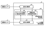
- FIG. 2 is a diagram illustrating an example of the configuration of the rail breakage detection device 4 according to the first embodiment and the vibration sensors 1 and 2.
- the rail breakage detection device 4 shown in FIG. 2 includes waveform separation units 41 and 42 and a waveform similarity determination unit 43.
- the waveform similarity determination unit 43 includes an impulse waveform similarity determination unit 44 and a continuous waveform similarity determination unit 45.
- the waveform separation unit 41 which is the first waveform separation unit, separates the output waveform of the vibration sensor 1 into an impulse waveform and a continuous waveform and outputs them.
- the impulse waveform that is the forced vibration component is referred to as a first impulse waveform for convenience, and the continuous waveform that is the free vibration component is referred to as a first continuous waveform for convenience.
- a waveform separation unit 42 as a second waveform separation unit separates the output waveform of the vibration sensor 2 into an impulse waveform and a continuous waveform and outputs the separated waveform.
- This impulse waveform is referred to as a second impulse waveform for convenience, and this continuous waveform is referred to as a second continuous waveform for convenience.
- examples of the method for performing waveform separation include waveform analysis, time-frequency analysis, Fourier analysis, wavelet analysis, and sparse analysis.
- the waveform similarity determination unit 43 compares the output waveform from the waveform separation unit 41 and the output waveform from the waveform separation unit 42 using at least one of the impulse waveform similarity determination unit 44 and the continuous waveform similarity determination unit 45. Then, the similarity is determined, and rail breakage is detected from the similarity.
- the waveform similarity determination unit 43 performs comparison using an impulse waveform when the train 3 approaches the vibration sensors 1 and 2, and performs comparison using a continuous waveform when the train 3 moves away from the vibration sensors 1 and 2.
- the impulse waveform similarity determination unit 44 compares the first impulse waveform from the waveform separation unit 41 with the second impulse waveform from the waveform separation unit 42 and determines the similarity of the impulse waveform.
- the continuous waveform similarity determination unit 45 compares the first continuous waveform from the waveform separation unit 41 and the second continuous waveform from the waveform separation unit 42 to determine the similarity of the continuous waveforms.
- a method of comparing RMS (Root Mean Square) values can be exemplified.
- RMS Root Mean Square
- the strongest value of the impulse vibration may be compared, or the cross-correlation values of the time series data may be compared.
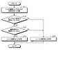
- FIG. 3 is a flowchart showing an example of the operation of the rail breakage detection device 4 in the first embodiment.
- the waveform separators 41 and 42 continuously use the waveforms from the two vibration sensors as the compulsory vibration component and the impulse waveform component, and the free vibration component and the continuous waveform component. Separated into waveforms (S11).
- the impulse waveform similarity determination unit 44 determines whether or not the impulse waveforms are similar (S12).
- the continuous waveform similarity determination unit 45 determines whether the continuous waveform components of the separated waveforms are similar (S13).
- the waveform similarity determination unit 43 determines that there is no rail fracture (S14), and ends the process.
- the waveform similarity determination unit 43 determines that there is a rail break (S15), and performs processing. finish.
- the waveform similarity determination unit 43 uses both the impulse waveform and the continuous waveform.
- the waveform similarity determination unit 43 is at least one of the impulse waveform similarity determination unit 44 and the continuous waveform similarity determination unit 45. As long as it has.
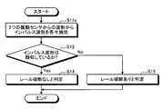
- FIG. 4 is a flowchart illustrating an example of the operation of the rail breakage detection device 4 when the waveform similarity determination unit 43 does not include the continuous waveform similarity determination unit 45 in the first embodiment.
- the waveform separators 41 and 42 extract impulse waveforms, which are compulsory vibration components and impulse waveform components, from the waveforms from the two vibration sensors (S11a).
- the impulse waveform similarity determination unit 44 determines whether or not the extracted impulse waveforms are similar (S12). When the impulse waveforms are similar (S12: Yes), the waveform similarity determination unit 43 determines that there is no rail break (S14) and ends the process. When the impulse waveforms are not similar (S12: No), the waveform similarity determination unit 43 determines that there is a rail break (S15) and ends the process.
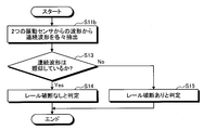
- FIG. 5 is a flowchart illustrating an example of the operation of the rail breakage detection device 4 when the waveform similarity determination unit 43 does not include the impulse waveform similarity determination unit 44 in the first embodiment.
- the processing is started, and the waveform separators 41 and 42 respectively extract continuous waveforms as free vibration components from the waveforms from the two vibration sensors (S11b).
- the continuous waveform similarity determination unit 45 determines whether or not the extracted continuous waveforms are similar (S13). When the continuous waveforms are similar (S13: Yes), the waveform similar (S13: Yes), the waveform similarity determination unit 43 determines that there is no rail fracture (S14), and ends the process. If the continuous waveforms are not similar (S13: No), the waveform similarity determination unit 43 determines that there is a rail break (S15), and ends the process.
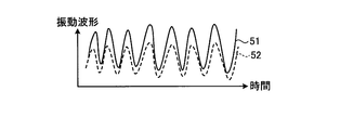
- FIG. 6 is a diagram showing an example of a vibration waveform when the two rails are not broken.
- FIG. 7 is a diagram illustrating an example of a vibration waveform when one of the two rails is broken.
- the output waveform 51 of the vibration sensor 1 and the output waveform 52 of the vibration sensor 2 have similar waveform shapes.
- the output waveform 61 of the vibration sensor 1 and the output waveform 62 of the vibration sensor 2 have dissimilar waveform shapes.
- the threshold for determination is determined for each rail installation environment by comparing the output waveforms of a plurality of vibration sensors mounted at different locations on the rail and determining the similarity.
- Rail breakage can be detected with a simple configuration without setting values one by one, that is, regardless of the rail installation environment. Further, the detection accuracy can be improved by separating the output waveform of the vibration sensor into an impulse waveform and a continuous waveform.
- the rail breakage detection device 4 includes at least a processor, a memory, and an input unit, and the operation of each device is realized by software.
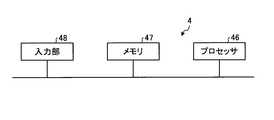
- FIG. 8 is a diagram illustrating an example of a general configuration of hardware for realizing the rail breakage detection device 4 according to the present embodiment.
- the apparatus shown in FIG. 8 includes a processor 46, a memory 47, and an input unit 48.
- the processor 46 performs calculation and control by software using the received data.
- the memory 47 stores received data or data and software necessary for the processor 46 to perform calculation and control.
- the input unit 48 receives the output waveforms of the vibration sensors 1 and 2 as input.
- a plurality of processors 46 and memories 47 may be provided.
- Embodiment 2 FIG. In the first embodiment, the mode in which the two vibration sensors are mounted on different rails has been described. However, the present invention is not limited to this. As shown in the present embodiment, two vibration sensors may be mounted on the same rail.
- FIG. 9 is a diagram illustrating an example of the rail breakage detection device 4 and the peripheral configuration according to the second embodiment of the present invention.
- FIG. 9 shows a vibration sensor 1 that is a first vibration sensor mounted on one of the two rails, and a second vibration sensor mounted on the same rail as the rail on which the vibration sensor 1 is mounted.
- a vibration sensor 2a, a train 3 traveling on two rails, and a rail breakage detection device 4 are shown.
- the train 3 travels on two rails so as to approach the vibration sensors 1 and 2a.
- the output waveform 51 of the vibration sensor 1 and the vibration The output waveform 52 of the sensor 2a has a similar waveform shape, and when the rail to which the vibration sensor 2a is attached is broken, the output waveform of the vibration sensor 1 and the output waveform of the vibration sensor 2a are not similar. It becomes a shape.
- the propagation time of the propagating wave changes. Also, by performing within the propagation time width set in advance when calculating the similarity of the waveform, the vibration sensor 1 The output waveform and the output waveform of the vibration sensor 2a have a dissimilar waveform shape.
- the rail breakage is detected from the similarity of the vibrations of the rails at two or more different locations. Therefore, the rail material, the rail facility method, and the ground where the rails are installed are affected. Therefore, it is not necessary to set a threshold value for detecting rail breakage.
- the technology that detects the breakage of the rail by referring to the current value cannot detect the case where the rail is partially broken. According to the first and second embodiments, since no current is used, partial rail breakage can be detected.
- vibration information measured by a plurality of vibration sensors is compared, there is no false detection due to shock waves caused by crossing the vehicle.
- this invention is not limited to this, The vibration sensor should just be provided with two or more.
- Embodiment 1, 2 it is preferable to apply Embodiment 1, 2 to the area containing the curve part on a route. This is because the rail breakage is likely to occur in the curved portion on the route due to friction with the wheel. It is particularly preferable to apply to a portion where the radius of curvature of the curved portion on the route is small.
- this embodiment is also preferably applied to a section including a weld on a route. This is because rail breakage tends to occur at the welded portion on the route.
- the configuration described in the above embodiment shows an example of the contents of the present invention, and can be combined with another known technique, and can be combined with other configurations without departing from the gist of the present invention. It is also possible to omit or change the part.
Landscapes
- Engineering & Computer Science (AREA)
- Physics & Mathematics (AREA)
- General Physics & Mathematics (AREA)
- Mechanical Engineering (AREA)
- Aviation & Aerospace Engineering (AREA)
- Health & Medical Sciences (AREA)
- Biomedical Technology (AREA)
- General Health & Medical Sciences (AREA)
- Train Traffic Observation, Control, And Security (AREA)
- Measurement Of Mechanical Vibrations Or Ultrasonic Waves (AREA)
- Testing Of Devices, Machine Parts, Or Other Structures Thereof (AREA)
Abstract
レールの設置環境によらず、簡易な構成で実現可能なレール破断検知装置を得ることを目的とし、レールの異なる箇所に各々装着された第1の振動センサ1からの出力波形及び第2の振動センサ2からの出力波形が入力されて、これらの出力波形の類似度を判定する波形類似度判定部43を備え、レールの破断を検知する。第1の振動センサ1と第2の振動センサ2とは、同一のレールに装着されていてもよいし、異なるレールに装着されていてもよい。
Description
本発明は、レール破断検知装置に関するものである。
従来技術である特許文献1には、レールに設置した振動センサの振動情報のしきい値判定によりレールの破断検知を行う技術が開示されている。
しかしながら、上記従来技術によれば、レールの破断検知にレールの共振周波数を用いている。そのため、レールの設置環境毎に判定用のしきい値を逐一設定しなければならない、という問題があった。
本発明は、上記に鑑みてなされたものであって、レールの設置環境によらず、簡易な構成で実現可能なレール破断検知装置を得ることを目的とする。
上述した課題を解決し、目的を達成するために、本発明は、レールの異なる箇所に各々装着された複数の振動センサの出力波形が入力されるレール破断検知装置であって、複数の前記出力波形を比較して類似度を判定する波形類似度判定部を備え、前記レールの破断を検知することを特徴とする。
本発明によれば、レールの設置環境によらず、簡易な構成で実現可能なレール破断検知装置を得ることができる、という効果を奏する。
以下に、本発明の実施の形態にかかるレール破断検知装置を図面に基づいて詳細に説明する。なお、この実施の形態によりこの発明が限定されるものではない。
実施の形態1.
図1は、本発明の実施の形態1にかかるレール破断検知装置4及び周辺構成の一例を示す図である。図1には、2本のレールの一方に装着された第1の振動センサである振動センサ1と、2本のレールの他方に装着された第2の振動センサである振動センサ2と、2本のレール上を走行する列車3と、レール破断検知装置4とが示されている。振動センサ1,2は、レールの振動を計測する。列車3は、振動センサ1,2に近づく方向に2本のレール上を走行している。
図1は、本発明の実施の形態1にかかるレール破断検知装置4及び周辺構成の一例を示す図である。図1には、2本のレールの一方に装着された第1の振動センサである振動センサ1と、2本のレールの他方に装着された第2の振動センサである振動センサ2と、2本のレール上を走行する列車3と、レール破断検知装置4とが示されている。振動センサ1,2は、レールの振動を計測する。列車3は、振動センサ1,2に近づく方向に2本のレール上を走行している。
図2は、実施の形態1にかかるレール破断検知装置4の構成の一例と、振動センサ1,2とを示す図である。図2に示すレール破断検知装置4は、波形分離部41,42と、波形類似度判定部43とを備える。波形類似度判定部43は、インパルス波形類似度判定部44と、連続波形類似度判定部45とを備える。
第1の波形分離部である波形分離部41は、振動センサ1の出力波形をインパルス波形と連続波形とに分離して出力する。この強制振動成分であるインパルス波形を便宜上第1のインパルス波形と記載し、この自由振動成分である連続波形を便宜上第1の連続波形と記載する。第2の波形分離部である波形分離部42は、振動センサ2の出力波形をインパルス波形と連続波形とに分離して出力する。このインパルス波形を便宜上第2のインパルス波形と記載し、この連続波形を便宜上第2の連続波形と記載する。ここで、波形分離を行う方法には、波形解析、時間周波数解析、フーリエ解析、ウェーブレット解析及びスパース解析を例示することができる。
波形類似度判定部43は、インパルス波形類似度判定部44及び連続波形類似度判定部45の少なくとも一方を用いて、波形分離部41からの出力波形と波形分離部42からの出力波形とを比較して類似度の判定を行い、この類似度からレール破断を検知する。波形類似度判定部43は、列車3が振動センサ1,2に近づく際にはインパルス波形により比較を行い、列車3が振動センサ1,2から遠ざかる際には連続波形により比較を行う。
インパルス波形類似度判定部44は、波形分離部41からの第1のインパルス波形と、波形分離部42からの第2のインパルス波形とを比較してインパルス波形の類似度の判定を行う。
連続波形類似度判定部45は、波形分離部41からの第1の連続波形と、波形分離部42からの第2の連続波形とを比較して連続波形の類似度の判定を行う。
ここで、波形類似度を判定する波形比較には、RMS(Root Mean Square)値を比較する方法を例示することができる。RMS値を比較する場合には、振動強度のRMS値の比が予め決められたしきい値の範囲内に収まっていればレール破断していないと判定し、振動強度のRMS値の比が予め決められたしきい値の範囲内に収まっていなければレール破断していると判定する。又は、波形類似度を判定する波形比較には、インパルス振動の最も強い値を比較してもよいし、時系列データの相互相関値を比較してもよい。
図3は、実施の形態1においてレール破断検知装置4の動作の一例を示すフローチャートである。まず、処理をスタートし、波形分離部41,42が、2つの振動センサからの波形を強制振動成分でありインパルス波形の成分であるインパルス波形と、自由振動成分であり連続波形の成分である連続波形とに各々分離する(S11)。次に、インパルス波形類似度判定部44が、インパルス波形が類似しているか否かを判定する(S12)。インパルス波形が類似している場合には(S12:Yes)、連続波形類似度判定部45が、分離された波形の連続波形成分が類似しているか否かを判定する(S13)。連続波形が類似している場合には(S13:Yes)、波形類似度判定部43は、レール破断なしと判定し(S14)、処理を終了する。インパルス波形が類似していない場合(S12:No)又は連続波形が類似していない場合(S13:No)には、波形類似度判定部43は、レール破断ありと判定し(S15)、処理を終了する。
なお、図2に示す波形類似度判定部43は、インパルス波形類似度判定部44と、連続波形類似度判定部45とを備え、図3においては、インパルス波形及び連続波形の双方を用いて波形の類似度を判定しているが、本発明はこれに限定されるものではなく、波形類似度判定部43は、インパルス波形類似度判定部44及び連続波形類似度判定部45の少なくともいずれか一方を備えていればよい。
図4は、実施の形態1において波形類似度判定部43が連続波形類似度判定部45を備えていない場合のレール破断検知装置4の動作の一例を示すフローチャートである。まず、処理をスタートし、波形分離部41,42が、2つの振動センサからの波形から強制振動成分でありインパルス波形の成分であるインパルス波形を各々抽出する(S11a)。次に、インパルス波形類似度判定部44が、抽出した各インパルス波形が類似しているか否かを判定する(S12)。インパルス波形が類似している場合には(S12:Yes)、波形類似度判定部43は、レール破断なしと判定し(S14)、処理を終了する。インパルス波形が類似していない場合(S12:No)には、波形類似度判定部43は、レール破断ありと判定し(S15)、処理を終了する。
図5は、実施の形態1において波形類似度判定部43がインパルス波形類似度判定部44を備えていない場合のレール破断検知装置4の動作の一例を示すフローチャートである。まず、処理をスタートし、波形分離部41,42が、2つの振動センサからの波形から自由振動成分である連続波形を各々抽出する(S11b)。次に、連続波形類似度判定部45が、抽出した各連続波形が類似しているか否かを判定する(S13)。連続波形が類似している場合には(S13:Yes)、波形類似度判定部43は、レール破断なしと判定し(S14)、処理を終了する。連続波形が類似していない場合(S13:No)には、波形類似度判定部43は、レール破断ありと判定し(S15)、処理を終了する。
図6は、2本のレールに破断がないときの振動波形の一例を示す図である。そして、図7は、2本のレールのいずれかに破断があるときの振動波形の一例を示す図である。図6においては2本のレールに破断がないので、振動センサ1の出力波形51と、振動センサ2の出力波形52とは類似した波形形状となる。図7においては振動センサ2が装着されたレールに破断があるので、振動センサ1の出力波形61と、振動センサ2の出力波形62とは非類似の波形形状となる。
このように、本実施の形態によれば、レールの異なる箇所に装着された複数の振動センサの出力波形を比較して類似度を判定することで、レールの設置環境毎に判定用のしきい値を逐一設定することなく、すなわち、レールの設置環境によらず、簡易な構成でレールの破断を検知することができる。また、振動センサの出力波形をインパルス波形と連続波形とに分離することで、検知精度を向上させることができる。
なお、上記説明した本実施の形態において、レール破断検知装置4は、少なくともプロセッサと、メモリと、入力部とを備え、各装置の動作はソフトウエアにより実現する。図8は、本実施の形態にかかるレール破断検知装置4を実現するハードウエアの一般的な構成の一例を示す図である。図8に示す装置は、プロセッサ46、メモリ47及び入力部48を備える。プロセッサ46は受信したデータを用いてソフトウエアによる演算及び制御を行う。メモリ47は受信したデータ又はプロセッサ46が演算及び制御を行うに際して必要なデータ及びソフトウエアの記憶を行う。入力部48は、振動センサ1,2の出力波形を入力とする。なお、プロセッサ46及びメモリ47は、各々複数設けられていてもよい。
実施の形態2.
実施の形態1においては、2つの振動センサを異なるレールに装着した形態について説明したが、本発明はこれに限定されるものではない。本実施の形態にて示すように、2つの振動センサが同一のレールに装着されていてもよい。
実施の形態1においては、2つの振動センサを異なるレールに装着した形態について説明したが、本発明はこれに限定されるものではない。本実施の形態にて示すように、2つの振動センサが同一のレールに装着されていてもよい。
図9は、本発明の実施の形態2にかかるレール破断検知装置4及び周辺構成の一例を示す図である。図9には、2本のレールの一方に装着された第1の振動センサである振動センサ1と、振動センサ1が装着されたレールと同一のレールに装着された第2の振動センサである振動センサ2aと、2本のレール上を走行する列車3と、レール破断検知装置4とが示されている。列車3は、振動センサ1,2aに近づくように2本のレール上を走行している。
図9に示すように、同一のレールに振動センサ1及び振動センサ2aが装着された場合であっても、2本のレールに破断がない場合には、振動センサ1の出力波形51と、振動センサ2aの出力波形52とは類似した波形形状となり、振動センサ2aが装着されたレールに破断がある場合には、振動センサ1の出力波形と、振動センサ2aの出力波形とは非類似の波形形状となる。なお、レールに破断がある場合には、伝搬する波の伝搬時間が変化するため、また、波形の類似度の演算時に予め設定された伝搬時間幅の範囲内で行うことで、振動センサ1の出力波形と、振動センサ2aの出力波形とは非類似の波形形状となる。
なお、実施の形態1,2によれば、レールの破断のみならず、レールの劣化を検知することも可能である。
レールの破断検知にレールの共振周波数を用いる技術では、レールの設置環境毎に判定用のしきい値を逐一設定しなければならない。実施の形態1,2によれば、異なる2つ以上の場所のレールの振動の類似度からレール破断を検知するので、レールの材質、レールの施設方法及びレールが設置された地盤の影響を受けないため、レール破断を検知するしきい値の設定が不要である。
また、電流値を参照することでレールの破断検知を行う技術では、レールが部分的に破断した場合を検知することができない。実施の形態1,2によれば、電流を用いないので、部分的なレール破断を検知することも可能である。
また、左右のレールの画像データを比較することでレールの破断検知を行う技術では、画像データを取得する画像センサが汚れに弱く、画像センサにはオイルミスト及び鉄粉が付着することが想定されるため、頻繁な保守作業を要する。実施の形態1,2では、このような頻繁な保守作業は不要である。
また、複数個の振動センサで計測した振動情報を比較するので、車両の踏切横断に起因する衝撃波による誤検知も生じない。なお、実施の形態1,2では2つの振動センサを用いる場合を例示したが、本発明はこれに限定されず、振動センサは複数個設けられていればよい。
なお、実施の形態1,2は、路線上の曲線部を含む区間に適用することが好ましい。路線上の曲線部では、車輪との摩擦によってレール破断が生じやすいからである。路線上の曲線部の曲率半径が小さい箇所に適用することが特に好ましい。
なお、本実施の形態は、路線上の溶接部を含む区間に適用することも好ましい。路線上の溶接部では、レール破断が生じやすいからである。
以上の実施の形態に示した構成は、本発明の内容の一例を示すものであり、別の公知の技術と組み合わせることも可能であるし、本発明の要旨を逸脱しない範囲で、構成の一部を省略、変更することも可能である。
1,2,2a 振動センサ、3 列車、4 レール破断検知装置、41,42 波形分離部、43 波形類似度判定部、44 インパルス波形類似度判定部、45 連続波形類似度判定部、46 プロセッサ、47 メモリ、48 入力部、51,52,61,62 出力波形。
Claims (9)
- レールの異なる箇所に各々装着された複数の振動センサの出力波形が入力されるレール破断検知装置であって、
複数の前記出力波形を比較して類似度を判定する波形類似度判定部を備え、
前記類似度により前記レールの破断を検知することを特徴とするレール破断検知装置。 - 前記複数の振動センサは同一のレールに設けられていることを特徴とする請求項1に記載のレール破断検知装置。
- 前記複数の振動センサが、路線上の曲線部を含む区間の振動を検知することを特徴とする請求項1に記載のレール破断検知装置。
- 前記複数の振動センサが、路線上の溶接部を含む区間の振動を検知することを特徴とする請求項1に記載のレール破断検知装置。
- レールに装着された第1の振動センサからの第1の出力波形と、前記第1の振動センサとは異なる位置に装着された第2の振動センサからの第2の出力波形とが入力されるレール破断検知装置であって、
前記第1の出力波形と前記第2の出力波形とを比較して前記第1の出力波形と前記第2の出力波形との類似度を判定する波形類似度判定部を備え、
前記類似度により前記レールの破断を検知することを特徴とするレール破断検知装置。 - レールに装着された第1の振動センサからの第1の出力波形と、前記第1の振動センサとは異なる位置に装着された第2の振動センサからの第2の出力波形とが入力されるレール破断検知装置であって、
前記第1の振動センサの出力波形を分離して第1のインパルス波形及び第1の連続波形を出力する第1の波形分離部と、
前記第2の振動センサの出力波形を分離して第2のインパルス波形及び第2の連続波形を出力する第2の波形分離部と、
前記第1のインパルス波形と前記第2のインパルス波形との比較及び前記第1の連続波形と前記第2の連続波形との比較の少なくともいずれか一方を行って、前記第1の出力波形と前記第2の出力波形との類似度を判定する波形類似度判定部とを備え、
前記類似度によりレールの破断を検知することを特徴とするレール破断検知装置。 - 前記第1の振動センサは、前記第2の振動センサと同一のレールに設けられていることを特徴とする請求項5又は請求項6に記載のレール破断検知装置。
- 前記第1及び第2の振動センサが、路線上の曲線部を含む区間の振動を検知することを特徴とする請求項5又は請求項6に記載のレール破断検知装置。
- 前記第1及び第2の振動センサが、路線上の溶接部を含む区間の振動を検知することを特徴とする請求項5又は請求項6に記載のレール破断検知装置。
Priority Applications (5)
| Application Number | Priority Date | Filing Date | Title |
|---|---|---|---|
| PCT/JP2016/061033 WO2017175276A1 (ja) | 2016-04-04 | 2016-04-04 | レール破断検知装置 |
| EP17779146.4A EP3441280B1 (en) | 2016-04-04 | 2017-04-04 | Rail breakage detection device |
| JP2018510619A JP6490302B2 (ja) | 2016-04-04 | 2017-04-04 | レール破断検知装置 |
| PCT/JP2017/014136 WO2017175768A1 (ja) | 2016-04-04 | 2017-04-04 | レール破断検知装置 |
| US16/079,696 US11572088B2 (en) | 2016-04-04 | 2017-04-04 | Rail break detection device |
Applications Claiming Priority (1)
| Application Number | Priority Date | Filing Date | Title |
|---|---|---|---|
| PCT/JP2016/061033 WO2017175276A1 (ja) | 2016-04-04 | 2016-04-04 | レール破断検知装置 |
Publications (1)
| Publication Number | Publication Date |
|---|---|
| WO2017175276A1 true WO2017175276A1 (ja) | 2017-10-12 |
Family
ID=60000982
Family Applications (2)
| Application Number | Title | Priority Date | Filing Date |
|---|---|---|---|
| PCT/JP2016/061033 Ceased WO2017175276A1 (ja) | 2016-04-04 | 2016-04-04 | レール破断検知装置 |
| PCT/JP2017/014136 Ceased WO2017175768A1 (ja) | 2016-04-04 | 2017-04-04 | レール破断検知装置 |
Family Applications After (1)
| Application Number | Title | Priority Date | Filing Date |
|---|---|---|---|
| PCT/JP2017/014136 Ceased WO2017175768A1 (ja) | 2016-04-04 | 2017-04-04 | レール破断検知装置 |
Country Status (4)
| Country | Link |
|---|---|
| US (1) | US11572088B2 (ja) |
| EP (1) | EP3441280B1 (ja) |
| JP (1) | JP6490302B2 (ja) |
| WO (2) | WO2017175276A1 (ja) |
Families Citing this family (9)
| Publication number | Priority date | Publication date | Assignee | Title |
|---|---|---|---|---|
| WO2017175276A1 (ja) * | 2016-04-04 | 2017-10-12 | 三菱電機株式会社 | レール破断検知装置 |
| US11433929B2 (en) * | 2017-04-04 | 2022-09-06 | Loram Technologies, Inc. | Railroad track guidance systems and methods |
| BR102017026315B1 (pt) * | 2017-12-06 | 2023-05-16 | Rumo Logística Operadora Multimodal S.A | Método para detecção de quebra de trilho ferroviário, sistema de detecção de quebra de trilho ferroviário e dispositivo detector de quebra de trilho ferroviário |
| FR3105148B1 (fr) * | 2019-12-23 | 2023-10-06 | Commissariat Energie Atomique | Systeme et procede pour la detection d’un defaut dans un rail d’une voie ferree |
| SE545220C2 (sv) * | 2020-06-03 | 2023-05-30 | Luleaa Tekniska Univ Avd Foer Drift Och Underhaallsteknik | Metod för att i omläggningsanordning mäta skador på spårväxlar och tåghjul |
| FR3114206B1 (fr) * | 2020-09-11 | 2023-01-06 | Commissariat Energie Atomique | Système et Procédé pour la détection de défauts dans des guides d’ondes allongés. |
| CN112945372A (zh) * | 2021-01-26 | 2021-06-11 | 深圳中慧轨道智能科技有限公司 | 一种滑床板断裂监测装置 |
| KR102671392B1 (ko) * | 2023-04-28 | 2024-05-31 | 한국철도기술연구원 | 복합 방식 레일절손 판단시스템 및 이를 이용한 레일절손 판단방법 |
| CN117184175A (zh) * | 2023-08-22 | 2023-12-08 | 北京交通大学 | 基于列车自激励与无线物联技术的断轨检测方法及系统 |
Citations (4)
| Publication number | Priority date | Publication date | Assignee | Title |
|---|---|---|---|---|
| JPH07333054A (ja) * | 1994-06-06 | 1995-12-22 | West Japan Railway Co | レールのき裂検知装置 |
| JPH11118770A (ja) * | 1997-10-20 | 1999-04-30 | Tokimec Inc | 超音波探傷方法及び装置 |
| JP2008151560A (ja) * | 2006-12-15 | 2008-07-03 | Univ Nagoya | 振動特性推定方法及び振動特性推定装置 |
| US20150068296A1 (en) * | 2012-04-06 | 2015-03-12 | The Regents Of The University Of California | Air-Coupled Ultrasonic Inspection Of Rails |
Family Cites Families (17)
| Publication number | Priority date | Publication date | Assignee | Title |
|---|---|---|---|---|
| DE4116650A1 (de) | 1991-05-22 | 1992-11-26 | Gerd R Dipl Ing Wetzler | Verfahren zur erkennung von schienenunterbrechungen bei endlos verschweissten eisenbahnschienen |
| US5743495A (en) * | 1997-02-12 | 1998-04-28 | General Electric Company | System for detecting broken rails and flat wheels in the presence of trains |
| GB0104688D0 (en) * | 2001-02-26 | 2001-04-11 | Roke Manor Research | Active rail health monitoring system |
| US6911914B2 (en) * | 2002-03-29 | 2005-06-28 | General Electric Company | Method and apparatus for detecting hot rail car surfaces |
| US6951132B2 (en) * | 2003-06-27 | 2005-10-04 | General Electric Company | Rail and train monitoring system and method |
| WO2006030786A1 (ja) * | 2004-09-13 | 2006-03-23 | Nsk Ltd. | 異常診断装置及び異常診断方法 |
| US20060076461A1 (en) * | 2004-10-12 | 2006-04-13 | General Electric Company | System and method for self powered wayside railway signaling and sensing |
| JP4569437B2 (ja) * | 2005-08-31 | 2010-10-27 | 日本精工株式会社 | 異常診断装置 |
| JP2010096541A (ja) * | 2008-10-14 | 2010-04-30 | Thk Co Ltd | 損傷検査装置、方法 |
| US20120279308A1 (en) * | 2011-05-04 | 2012-11-08 | Fbs, Inc. | Elastic wave rail defect detection system |
| CZ23860U1 (cs) * | 2012-04-18 | 2012-05-21 | Jaluvka@Otakar | Zařízení k monitoringu, detekci a diagnostice drážních vozidel pozemních, podzemních i nadzemních drah a jejich komponentů za jízdy |
| WO2014027977A1 (en) * | 2012-08-14 | 2014-02-20 | ENEKOM ENERJI EKOLOJI BILIŞIM VE MUHENDISLIK SANAYI TICARET LIMITED ŞlRKETI | A method for the detection of rail fractures and cracks |
| JP6297280B2 (ja) | 2013-08-09 | 2018-03-20 | 日本信号株式会社 | レール破断検知装置 |
| JP6465034B2 (ja) * | 2013-12-27 | 2019-02-06 | 日本電気株式会社 | 信号解析装置、加振力測定システム、信号解析方法および信号解析プログラム |
| CN107406090B (zh) * | 2015-01-16 | 2020-11-20 | 国际电子机械公司 | 异常车辆动态检测 |
| WO2017175276A1 (ja) * | 2016-04-04 | 2017-10-12 | 三菱電機株式会社 | レール破断検知装置 |
| CA3200604A1 (en) * | 2017-03-24 | 2018-09-24 | Canadian Pacific Railway Company | Condition based maintenance of railcar roller bearings using predictive wayside alerts based on acoustic bearing detector measurements |
-
2016
- 2016-04-04 WO PCT/JP2016/061033 patent/WO2017175276A1/ja not_active Ceased
-
2017
- 2017-04-04 JP JP2018510619A patent/JP6490302B2/ja not_active Expired - Fee Related
- 2017-04-04 WO PCT/JP2017/014136 patent/WO2017175768A1/ja not_active Ceased
- 2017-04-04 EP EP17779146.4A patent/EP3441280B1/en not_active Not-in-force
- 2017-04-04 US US16/079,696 patent/US11572088B2/en active Active
Patent Citations (4)
| Publication number | Priority date | Publication date | Assignee | Title |
|---|---|---|---|---|
| JPH07333054A (ja) * | 1994-06-06 | 1995-12-22 | West Japan Railway Co | レールのき裂検知装置 |
| JPH11118770A (ja) * | 1997-10-20 | 1999-04-30 | Tokimec Inc | 超音波探傷方法及び装置 |
| JP2008151560A (ja) * | 2006-12-15 | 2008-07-03 | Univ Nagoya | 振動特性推定方法及び振動特性推定装置 |
| US20150068296A1 (en) * | 2012-04-06 | 2015-03-12 | The Regents Of The University Of California | Air-Coupled Ultrasonic Inspection Of Rails |
Also Published As
| Publication number | Publication date |
|---|---|
| WO2017175768A1 (ja) | 2017-10-12 |
| US20190300032A1 (en) | 2019-10-03 |
| EP3441280B1 (en) | 2021-12-29 |
| JPWO2017175768A1 (ja) | 2018-08-09 |
| JP6490302B2 (ja) | 2019-03-27 |
| US11572088B2 (en) | 2023-02-07 |
| EP3441280A4 (en) | 2019-05-15 |
| EP3441280A1 (en) | 2019-02-13 |
Similar Documents
| Publication | Publication Date | Title |
|---|---|---|
| WO2017175276A1 (ja) | レール破断検知装置 | |
| JP5404572B2 (ja) | ケーブルの故障箇所検知システム及び方法 | |
| CN103119461B (zh) | 声源检测装置 | |
| EP3102932B1 (en) | Method for crack monitoring | |
| US10697861B2 (en) | Structure abnormality detection device, structure abnormality detection method, storage medium, and structure abnormality detection system | |
| CN105549017A (zh) | 物体检测装置 | |
| WO2008143114A1 (ja) | 物体検出装置及び物体検出方法 | |
| CN103988090A (zh) | 声源检测装置 | |
| CN104424808A (zh) | 一种导航提示方法及装置、导航系统 | |
| JP6327297B2 (ja) | 交通情報取得装置、交通情報取得方法、および交通情報取得プログラム | |
| CN108918173A (zh) | 一种检测受电弓或网线故障的方法及系统 | |
| JP5453765B2 (ja) | 道路形状推定装置 | |
| WO2018106677A1 (en) | Ultrasonic inspection of railroad tracks | |
| JP5867351B2 (ja) | 走行音を用いた車両検出装置 | |
| JP2016016731A (ja) | 列車位置検出システムおよび列車位置検出方法、ならびに、プログラム | |
| JP6850185B2 (ja) | 空隙判定方法、空隙判定システム及び弾性波検出方法 | |
| JP6614889B2 (ja) | Aeを利用した床版劣化範囲あるいは床版劣化状況の検知方法 | |
| JP6365633B2 (ja) | 車長推定装置、交通管制システム、車長推定方法、および車長推定プログラム | |
| JP2012146149A (ja) | 死角車両検知システム、死角車両検知装置、死角車両検知方法およびそのプログラム | |
| JP7305854B2 (ja) | 検知システムおよび検知方法 | |
| JP6866666B2 (ja) | 交通状況監視装置、車両監視システム、交通状況監視方法、および交通状況監視プログラム | |
| KR101803648B1 (ko) | 자율주행제어장치 및 자율주행제어방법 | |
| JP6426586B2 (ja) | 物体検知装置 | |
| JP3821754B2 (ja) | スクリーンの異常検出装置 | |
| JP2020074212A5 (ja) | 逆走検知装置、逆走検知方法および逆走検知プログラム |
Legal Events
| Date | Code | Title | Description |
|---|---|---|---|
| NENP | Non-entry into the national phase |
Ref country code: DE |
|
| 121 | Ep: the epo has been informed by wipo that ep was designated in this application |
Ref document number: 16897835 Country of ref document: EP Kind code of ref document: A1 |
|
| 122 | Ep: pct application non-entry in european phase |
Ref document number: 16897835 Country of ref document: EP Kind code of ref document: A1 |
|
| NENP | Non-entry into the national phase |
Ref country code: JP |