EP3441280B1 - Rail breakage detection device - Google Patents
Rail breakage detection device Download PDFInfo
- Publication number
- EP3441280B1 EP3441280B1 EP17779146.4A EP17779146A EP3441280B1 EP 3441280 B1 EP3441280 B1 EP 3441280B1 EP 17779146 A EP17779146 A EP 17779146A EP 3441280 B1 EP3441280 B1 EP 3441280B1
- Authority
- EP
- European Patent Office
- Prior art keywords
- vibration
- waveform
- rail
- train
- rail break
- Prior art date
- Legal status (The legal status is an assumption and is not a legal conclusion. Google has not performed a legal analysis and makes no representation as to the accuracy of the status listed.)
- Not-in-force
Links
Images


Classifications
-
- B—PERFORMING OPERATIONS; TRANSPORTING
- B61—RAILWAYS
- B61L—GUIDING RAILWAY TRAFFIC; ENSURING THE SAFETY OF RAILWAY TRAFFIC
- B61L23/00—Control, warning or like safety means along the route or between vehicles or trains
- B61L23/04—Control, warning or like safety means along the route or between vehicles or trains for monitoring the mechanical state of the route
- B61L23/042—Track changes detection
- B61L23/044—Broken rails
-
- B—PERFORMING OPERATIONS; TRANSPORTING
- B61—RAILWAYS
- B61L—GUIDING RAILWAY TRAFFIC; ENSURING THE SAFETY OF RAILWAY TRAFFIC
- B61L27/00—Central railway traffic control systems; Trackside control; Communication systems specially adapted therefor
- B61L27/50—Trackside diagnosis or maintenance, e.g. software upgrades
- B61L27/53—Trackside diagnosis or maintenance, e.g. software upgrades for trackside elements or systems, e.g. trackside supervision of trackside control system conditions
-
- G—PHYSICS
- G01—MEASURING; TESTING
- G01H—MEASUREMENT OF MECHANICAL VIBRATIONS OR ULTRASONIC, SONIC OR INFRASONIC WAVES
- G01H1/00—Measuring characteristics of vibrations in solids by using direct conduction to the detector
-
- G—PHYSICS
- G01—MEASURING; TESTING
- G01M—TESTING STATIC OR DYNAMIC BALANCE OF MACHINES OR STRUCTURES; TESTING OF STRUCTURES OR APPARATUS, NOT OTHERWISE PROVIDED FOR
- G01M5/00—Investigating the elasticity of structures, e.g. deflection of bridges or air-craft wings
- G01M5/0033—Investigating the elasticity of structures, e.g. deflection of bridges or air-craft wings by determining damage, crack or wear
-
- G—PHYSICS
- G01—MEASURING; TESTING
- G01M—TESTING STATIC OR DYNAMIC BALANCE OF MACHINES OR STRUCTURES; TESTING OF STRUCTURES OR APPARATUS, NOT OTHERWISE PROVIDED FOR
- G01M5/00—Investigating the elasticity of structures, e.g. deflection of bridges or air-craft wings
- G01M5/0066—Investigating the elasticity of structures, e.g. deflection of bridges or air-craft wings by exciting or detecting vibration or acceleration
-
- G—PHYSICS
- G01—MEASURING; TESTING
- G01M—TESTING STATIC OR DYNAMIC BALANCE OF MACHINES OR STRUCTURES; TESTING OF STRUCTURES OR APPARATUS, NOT OTHERWISE PROVIDED FOR
- G01M7/00—Vibration-testing of structures; Shock-testing of structures
- G01M7/02—Vibration-testing by means of a shake table
Definitions
- the present invention relates to a rail break detection device.
- Japanese Patent Application JP 2015-34452 A which is a related art, discloses a technology for detecting a break on a rail by determination using a threshold of vibration information from a vibration sensor provided on the rail.
- Document US 5 743 495 A shows a redundant sensor system for predicting railway hazards including breaks in each rail, the location of the breaks, and determining when a railway vehicle has a flat wheel.
- Vibration sensors are distributed along both rails of a railway. Each sensor has a detection band at least within the sensing range of adjacent sensors and it is positioned such that the sensor detects vibration in both the horizontal and vertical axis of the rail.
- a central processor evaluates the data from these sensors and identifies the rail break, the location of the break, and the flat wheel.
- the present invention has been made in view of the above, and an object thereof is to provide a rail break detection device that can be achieved regardless of the environment in which rails are laid.
- a rail break detection device to which a first output waveform from a first vibration sensor mounted on rails and a second output waveform from a second vibration sensor mounted at a different position from the first vibration sensor are input, the rail break detection device comprising a first waveform separation unit configured to separate the first output waveform of the first vibration sensor and output a first impulse waveform, which is a forced vibration component, and a first continuous waveform, which is a free vibration component; a second waveform separation unit configured to separate the second output waveform of the second vibration sensor and output a second impulse waveform, which is a forced vibration component, and a second continuous waveform, which is a free vibration component; and a waveform similarity determination unit configured to perform at least one of comparison between the first impulse waveform and the second impulse waveform and comparison between the first continuous waveform and the second continuous waveform, and determine similarity between the first output waveform and the second output waveform, wherein a break of rails is detected on the basis
- an effect of providing a rail break detection device that can be achieved regardless of the environment in which rails are laid is produced.
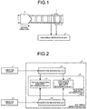
- FIG. 1 is a diagram illustrating a rail break detection device 4 according to a first embodiment of the present invention and structures in the vicinity.
- FIG. 1 illustrates a vibration sensor 1, which is a first vibration sensor mounted on one of two rails, a vibration sensor 2, which is a second vibration sensor mounted on the other of the two rails at a position facing the vibration sensor 1, a train 3 that moves along the two rails, and the rail break detection device 4.
- the vibration sensors 1 and 2 are mounted on different rails from each other, which are parallel to each other.
- the vibration sensors 1 and 2 measure vibration of the rails.
- the train 3 is moving along the two rails in the direction toward the vibration sensors 1 and 2.
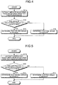
- FIG. 2 is a diagram illustrating a configuration of the rail break detection device 4 according to the first embodiment, and the vibration sensors 1 and 2.
- the rail break detection device 4 illustrated in FIG. 2 includes waveform separation units 41 and 42, and a waveform similarity determination unit 43.
- the waveform similarity determination unit 43 includes an impulse waveform similarity determination unit 44, and a continuous waveform similarity determination unit 45.
- the waveform separation unit 41 which is a first waveform separation unit, separates a waveform output from the vibration sensor 1 into an impulse waveform and a continuous waveform and outputs the impulse waveform and the continuous waveform.
- the impulse waveform which is a forced vibration component
- the continuous waveform which is a free vibration component
- the waveform separation unit 42 which is a second waveform separation unit, separates a waveform output from the vibration sensor 2 into an impulse waveform and a continuous waveform and outputs the impulse waveform and the continuous waveform.
- the impulse waveform will be referred to as a second impulse waveform for convenience sake, and the continuous waveform will be referred to as a second continuous waveform for convenience sake.
- examples of methods for waveform separation include waveform analysis, time frequency analysis, Fourier analysis, wavelet analysis, and sparse analysis.
- the waveform similarity determination unit 43 compares a waveform output from the waveform separation unit 41 with a waveform output from the waveform separation unit 42 to determine similarity between the waveforms by using the impulse waveform similarity determination unit 44 or the continuous waveform similarity determination unit 45, and detects a rail break from the similarity.
- the waveform similarity determination unit 43 compares impulse waveforms by using the impulse waveform similarity determination unit 44 when the train 3 moves toward the vibration sensors 1 and 2, and compares continuous waveforms by using the continuous waveform similarity determination unit 45 when the train 3 moves away from the vibration sensors 1 and 2.
- impulse waveforms are used for similarity determination because the impulse waveform components are large; when the train 3 moves away from the vibration sensors 1 and 2, continuous waveform components are used for similarity determination because the impulse waveform components are attenuated.
- the impulse waveform similarity determination unit 44 compares the first impulse waveform from the waveform separation unit 41 with the second impulse waveform from the waveform separation unit 42 to determine similarity between the impulse waveforms.
- the continuous waveform similarity determination unit 45 compares the first continuous waveform from the waveform separation unit 41 with the second continuous waveform from the waveform separation unit 42 to determine similarity between the continuous waveforms.
- examples of waveform comparison for determining waveform similarity include a method of comparing root mean square (RMS) values.
- RMS root mean square
- highest values of impulse vibration may be compared or correlation values of time-series data may be compared.
- FIG. 3 is a flowchart illustrating operation of the rail break detection device 4 in the first embodiment.
- processing is started, and the waveform separation units 41 and 42 separate waveforms from the two vibration sensors 1 and 2, respectively, into impulse waveforms, which are forced vibration components, and continuous waveforms, which are free vibration components (S11).
- the impulse waveform similarity determination unit 44 determines whether or not the two impulse waveforms obtained by the separation are similar to each other (S12). If the impulse waveforms are similar to each other (S12: Yes), the continuous waveform similarity determination unit 45 determines whether or not the two continuous waveforms obtained by the separation are similar to each other (S13).
- the waveform similarity determination unit 43 determines that no rail break is present (S14), and terminates the processing. If the impulse waveforms are not similar to each other (S12: No) or if the continuous waveforms are not similar to each other (S13: No), the waveform similarity determination unit 43 determines that a rail break is present (S15), and terminates the processing.
- the waveform similarity determination unit 43 illustrated in FIG. 2 includes both of the impulse waveform similarity determination unit 44 and the continuous waveform similarity determination unit 45, the present invention is not limited thereto, and the waveform similarity determination unit 43 may include at least either one of the impulse waveform similarity determination unit 44 and the continuous waveform similarity determination unit 45. In a case where the waveform similarity determination unit 43 does not include the impulse waveform similarity determination unit 44 but includes the continuous waveform similarity determination unit 45, determination on the similarity of waveforms may be performed when the train 3 moves away from the vibration sensors 1 and 2.
- FIG. 4 is a flowchart illustrating operation of the rail break detection device 4 in a case where the waveform similarity determination unit 43 does not include the continuous waveform similarity determination unit 45 in the first embodiment.
- the waveform separation units 41 and 42 extract impulse waveforms, which are forced vibration components, from waveforms from the two vibration sensors, respectively (S11a).
- the impulse waveform similarity determination unit 44 determines whether or not the extracted impulse waveforms are similar to each other (S12). If the impulse waveforms are similar to each other (S12: Yes), the waveform similarity determination unit 43 determines that no rail break is present (S14), and terminates the processing. If the impulse waveforms are not similar to each other (S12: No), the waveform similarity determination unit 43 determines that a rail break is present (S15) and terminates the processing.
- FIG. 5 is a flowchart illustrating operation of the rail break detection device 4 in a case where the waveform similarity determination unit 43 does not include the impulse waveform similarity determination unit 44 in the first embodiment.
- the waveform separation units 41 and 42 extract continuous waveforms, which are free vibration components, from waveforms from the two vibration sensors, respectively (S11b).
- the continuous waveform similarity determination unit 45 determines whether or not the extracted continuous waveforms are similar to each other (S13). If the continuous waveforms are similar to each other (S13: Yes), the waveform similarity determination unit 43 determines that no rail break is present (S14), and terminates the processing. If the continuous waveforms are not similar to each other (S13: No), the waveform similarity determination unit 43 determines that a rail break is present (S15), and terminates the processing.
- output of the result of detection of the presence or absence of a rail break to a railroad map, a display device, a signal, or the like allows users to know the presence or absence of the rail break.
- the information given to users through a railroad map, a display device, a signal, or the like may be train availability information instead of the presence or absence of a rail break.
- FIG. 6 is a graph illustrating vibration waveforms when no break is present on two rails in the first embodiment.
- FIG. 7 is a graph illustrating vibration waveforms when a break is present on either of two rails in the first embodiment.
- an output waveform 51 from the vibration sensor 1 and an output waveform 52 from the vibration sensor 2 have waveform profiles similar to each other.
- an output waveform 61 from the vibration sensor 1 and an output waveform 62 from the vibration sensor 2 have waveform profiles dissimilar to each other.
- waveforms output from a plurality of vibration sensors mounted on two rails at positions facing each other are compared and similarity between the waveforms is determined, so that a difference between the conditions of the two rails is detected without thresholds for determination set for each environment in which rails are laid, which allows detection of a rail break regardless of the environment in which the rails are laid.
- an output waveform from a vibration sensor is separated into an impulse waveform and a continuous waveform, which improves accuracy of the detection.
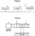
- FIG. 8 is a diagram illustrating a typical hardware configuration for implementing the rail break detection device 4 according to the present embodiment.
- the device illustrated in FIG. 8 includes a processor 46, a memory 47, and an input unit 48.
- the processor 46 performs computation and control by software by using received data.
- the memory 47 stores received data, stores data necessary for the processor 46 to perform computation and control, and stores software for the processor 46 to perform computation and control.
- the input unit 48 inputs output waveforms from the vibration sensors 1 and 2.
- the waveform separation units 41 and 42 are implemented by the processor 46, the memory 47, and the input unit 48, and the waveform similarity determination unit 43 is implemented by the processor 46 and the memory 47. Note that a plurality of processors 46 and a plurality of memories 47 may be provided.
- FIG. 9 is a diagram illustrating a rail break detection device 4 according to the second embodiment of the present invention and structures in the vicinity.
- FIG. 9 illustrates the vibration sensor 1, which is the first vibration sensor mounted on one of two rails, a vibration sensor 2a, which is the second vibration sensor mounted on the same rail as the rail on which the vibration sensor 1 is mounted, the train 3 that moves along the two rails, and the rail break detection device 4.
- the vibration sensors 1 and 2a measure vibration of the rail.
- the train 3 is moving along the two rails in the direction toward the vibration sensors 1 and 2a.
- the rail on which a break can be detected by the vibration sensors 1 and 2a is the rail on which the vibration sensors 1 and 2a are mounted.
- vibration sensors are also mounted on the rail on which the vibration sensors 1 and 2a are not mounted similarly to the vibration sensors 1 and 2a.
- the output waveform 51 from the vibration sensor 1 and the output waveform 52 from the vibration sensor 2a have waveform profiles similar to each other when no break is present on the two rails, and the output waveform from the vibration sensor 1 and the output waveform from the vibration sensor 2a have waveform profiles dissimilar to each other when a break is present on the rail on which the vibration sensor 2a is mounted.
- the output waveform from the vibration sensor 1 and the output waveform from the vibration sensor 2a have waveform profiles dissimilar to each other because the propagation times of propagating waves vary and because the computation of the similarity between waveforms is performed within a predetermined range of propagation time.
- the waveform from one of the two vibration sensors 1 and 2a has a waveform profile that is attenuated as compared to the waveform from the other.
- deterioration refers to a state in which abnormality has occurred inside a rail although no break is observed from the appearance of the rail.
- a threshold for determination has to be set for each environment in which rails are laid.
- a rail break is detected on the basis of similarity between vibrations of rails at two or more different positions, which is not affected by the material of the rails, the way in which the rails are laid, and the ground on which the rails are laid, and setting of a threshold for detecting a rail break thus need not be set for each environment in which the rails are laid.
- a partial break of a rail cannot be detected.
- a partial rail break can be detected. Note that, while the vibration waveform when a rail break is present as illustrated in FIG. 7 is dissimilar to the vibration waveform when no rail break is present as illustrated in FIG. 6 , a vibration waveform similar to the vibration waveform when no rail break is present as illustrated in FIG. 6 is obtained with a small RMS value when a partial rail break is present.
- image sensors for acquiring image data are vulnerable to dirt and it is envisaged that oil mist and iron powder adhere to image sensors, which requires frequent maintenance work. In the first and second embodiments, such frequent maintenance work is not needed.
- vibration information data obtained by measurement by a plurality of vibration sensors are compared, vibration caused by a vehicle crossing a railroad crossing or the like are cancelled out by the comparison. Thus, no false detection occurs owing to the crossing. While cases where two vibration sensors are used have been presented in the first and second embodiments, the present invention is not limited thereto and the number of vibration sensors may be any number larger than one.
- the first and second embodiments are preferably applied to a section including a curve on a railroad.
- any one of sections for detection by the vibration sensors include a curve of a railroad. This is because a rail break is likely to be caused by friction with wheels at a curve on a railroad. Application to a curve with a small radius of curvature on a railroad is particularly preferable.
- first and second embodiments are also preferably applied to a section including a weld on a railroad.
- any one of sections for detection by the vibration sensors include a weld of a railroad. This is because a rail break is likely to occur at a weld on a railroad.
- the present invention is not limited to the embodiments described in the first and second embodiments, but can also be applied to a radio train control system called communications based train control (CBTC).
- CBTC communications based train control
- an example of application to CBTC will be described. Note that, for details in the present embodiment that have already been described in the first and second embodiments, the first and second embodiments are to be referred to and redundant description will not be repeated.
- FIG. 10 is a first diagram illustrating a rail break detection device 4 according to the third embodiment of the present invention and structures in the vicinity.
- FIG. 10 illustrates, similarly to FIG. 1 , a vibration sensor 1, which is a first vibration sensor mounted on one of two rails, a vibration sensor 2, which is a second vibration sensor mounted on the other of the two rails at a position facing the vibration sensor 1, a train 3 that moves along the two rails, and the rail break detection device 4.
- the vibration sensors 1 and 2 measure vibration of the rails.
- the train 3 is moving along the two rails in the direction toward the vibration sensors 1 and 2.
- the same detection section is set for the vibration sensors 1 and 2 on the respective rails on which the vibration sensors 1 and 2 are mounted.
- the distance from an end of the detection section to the vibration sensors 1 and 2 is a distance within which the vibration sensors 1 and 2 can detect a rail break.
- a plurality of vibration sensors are provided on the rails on which the vibration sensors 1 and 2 are mounted so as to allow detection of a rail break in adjacent sections, and adjacent detection sections of the vibration sensors may overlap with each other. Adjacent detection sections of the vibration sensors partially overlapping with each other allow rail break detection without leaving a section in which a rail break cannot be detected on the rails.
- the vibration sensors 1 and 2 are preferably arranged at the center of the detection section, but the positions of the vibration sensors 1 and 2 are not limited as long as the positions are within the detection section.
- a ground radio device 6 communicates with a train radio device, which is not illustrated, mounted on the train 3 to acquire position information and speed information of the train 3, and transmits the acquired information to a ground control device 5.
- the rail break detection device 4 transmits a result of rail break detection to the ground control device 5.
- a central control device 7 is connected with the ground control device 5.
- the central control device 7 receives the position information and the speed information of the train 3 and the result of rail break detection from the ground control device 5, and controls operation of the train 3.
- the central control device 7 transmits an instruction to stop the train 3 to the train 3 via the ground control device 5 and the ground radio device 6 so as to stop the train 3.
- the rail break detection device 4 detects a rail break in the detection section of the vibration sensors 1 and 2 at a timing when the train 3 is moving at a point at a distance equal to or longer than a braking distance L of the train 3 before the end of the detection section of vibration sensors 1 and 2 on the side from which the train 3 is coming, and transmits the result of detection to the ground control device 5.
- the braking distance L can be calculated from the speed information of the train 3 and a coefficient of rolling friction.
- the central control device 7 can stop the train 3 before the train 3 enters the detection section of the vibration sensors 1 and 2 by performing control to stop the train 3 via the ground control device 5 and the ground radio device 6.
- a rail break can be detected and the train 3 can be stopped before the train 3 passes through the position of the rail break. Since the position information and the speed information of the train 3 are transmitted to the rail break detection device 4, the braking distance L of the train 3 can be calculated by the rail break detection device 4. Alternatively, the braking distance L may be calculated by the ground control device 5 or the central control device 7.
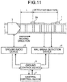
- FIG. 11 is a second diagram illustrating the rail break detection device 4 according to the third embodiment of the present invention and structures in the vicinity.
- FIG. 11 illustrates, similarly to FIG. 9 , the vibration sensor 1, which is the first vibration sensor mounted on one of two rails, a vibration sensor 2a, which is the second vibration sensor mounted on the same rail as the rail on which the vibration sensor 1 is mounted, the train 3 that moves along the two rails, and the rail break detection device 4.
- the vibration sensors 1 and 2a measure vibration of the rail.
- the train 3 is moving along the two rails in the direction toward the vibration sensors 1 and 2a.
- a section between the vibration sensor 1 and the vibration sensor 2a is set as the detection section.
- the positions at which the vibration sensor 1 and the vibration sensor 2a are installed are ends of the detection section, and the distance between the vibration sensor 1 and the vibration sensor 2a is a distance within which the vibration sensors 1 and 2a can detect a rail break.
- vibration sensors are similarly mounted the rail on which the vibration sensors 1 and 2a are not mounted.
- other vibration sensors are provided before the vibration sensor 1, so that adjacent detection sections of vibration sensors are arranged continuously similarly to FIG. 10 , which allows rail break detection without leaving a section in which a rail break cannot be detected on the rails.
- the ground radio device 6 communicates with the train radio device, which is not illustrated, mounted on the train 3 to acquire position information and speed information of the train 3, and transmits the acquired information to the ground control device 5.
- the rail break detection device 4 transmits a result of rail break detection to the ground control device 5.
- the central control device 7 is connected with the ground control device 5.
- the central control device 7 receives the position information and the speed information of the train 3 and the result of rail break detection from the ground control device 5, and controls operation of the train 3.
- the central control device 7 transmits an instruction to stop the train 3 to the train 3 via the ground control device 5 and the ground radio device 6 so as to stop the train 3.
- the rail break detection device 4 detects a rail break in the detection section defined by the vibration sensor 1 and the vibration sensor 2a at a timing when the train 3 is moving at a point at a distance equal to or more than the braking distance L of the train 3 before the vibration sensor 2a, and transmits the result of detection to the ground control device 5.
- the central control device 7 can stop the train 3 before the train 3 enters the detection section defined by the vibration sensor 1 and the vibration sensor 2a by performing control to stop the train 3 via the ground control device 5 and the ground radio device 6.
- a rail break can be detected and the train 3 can be stopped before the train 3 passes through the position of the rail break.
- the braking distance L of the train 3 can be calculated by the rail break detection device 4.
- the braking distance L may be calculated by the ground control device 5 or the central control device 7.
- a rail break can be detected and a train can be stopped before the train passes through the position of the rail break.
- a vibration exciter may be provided adjacent to a vibration sensor.
- vibration exciters are provided adjacent to the vibration sensors in the configuration of the third embodiment. Note that, for details in the present embodiment that have already been described in the first to third embodiments, the first to third embodiments are to be referred to and redundant description will not be repeated. While the embodiment in which vibration exciters are provided adjacent to the vibration sensors in the configuration of the third embodiment will be described in the present embodiment, the configuration of the present embodiment may be combined with the first or second embodiment.
- FIG. 12 is a first diagram illustrating a rail break detection device 4 according to the fourth embodiment of the present invention and structures in the vicinity.
- FIG. 12 illustrates, similarly to FIG. 1 , a vibration sensor 1, which is a first vibration sensor mounted on one of two rails, a vibration sensor 2, which is a second vibration sensor mounted on the other of the two rails at a position facing the vibration sensor 1, a train 3 that moves along the two rails, and the rail break detection device 4.
- the vibration sensors 1 and 2 measure vibration of the rails.
- the train 3 is moving along the two rails in the direction toward the vibration sensors 1 and 2.
- a vibration exciter 71 is provided before the vibration sensor 1 in the moving direction of the train 3, and a vibration exciter 72 is provided before the vibration sensor 2 in the moving direction of the train 3.
- the vibration exciters 71 and 72 applies vibration to the respective rails on which the vibration exciters 71 and 72 are installed at a timing when the train 3 is at a position at a distance equal to or longer than the braking distance L from the end of the detection section in accordance with an instruction from the central control device 7.
- the rail break detection device 4 detects a rail break by using the vibrations caused by the vibration exciters 71 and 72.
- any vibration exciters that can apply vibration to rails may be used, such as those having a configuration in which a piston hits a rail by electromagnetic force, for example.
- FIG. 13 is a second diagram illustrating a rail break detection device 4 according to the fourth embodiment of the present invention and structures in the vicinity.
- FIG. 13 illustrates, similarly to FIG. 9 , the vibration sensor 1, which is the first vibration sensor mounted on one of two rails, a vibration sensor 2a, which is the second vibration sensor mounted on the same rail as the rail on which the vibration sensor 1 is mounted, the train 3 that moves along the two rails, and the rail break detection device 4.
- the vibration sensors 1 and 2a measure vibration of the rail.
- the train 3 is moving along the two rails in the direction toward the vibration sensors 1 and 2a.
- a vibration exciter 71 is provided before the vibration sensor 1 in the moving direction of the train 3, and a vibration exciter 72a is provided before the vibration sensor 2a in the moving direction of the train 3.
- the vibration exciters 71 and 72a applies vibration to the respective rails on which the vibration exciters 71 and 72a are installed at a timing when the train 3 is at a position at a distance equal to or longer than the braking distance L from the end of the detection section in accordance with an instruction from the central control device 7 via the ground control device 5.
- the rail break detection device 4 detects a rail break by using the vibrations caused by the vibration exciters 71 and 72a.
- the rail break detection device 4 or the ground control device 5 may output an instruction to apply vibration to the vibration exciters 71 and 72 or 72a at a timing of rail break detection.
- vibration exciters 71 and 72 or 72a are provided before the vibration sensors 1 and 2 or 2a since the train 3 moves in one direction in FIGS. 12 and 13 , the present invention is not limited thereto. In a case where a railroad is a single track line, for example, vibration exciters may be provided on respective sides of a vibration sensor since the moving direction of the train is switched.
- a rail break can be detected and a train can be stopped before the train passes through the position of the rail break by using vibration applied by a vibration exciter.
- a rail break can be detected by using vibration applied by a vibration exciter.
- a rail break can also be detected by using both of vibration caused by a train 3 present before a vibration sensor in the moving direction of the train and vibration caused by a train 3a present ahead of the vibration sensor in the moving direction. Note that, for details in the present embodiment that have already been described in the first to fourth embodiments, the first to fourth embodiments are to be referred to and redundant description will not be repeated. Note that, in the present embodiment, an embodiment in which a train 3 is present before the vibration sensors in the train moving direction in the configuration of the third embodiment and a train 3a is present ahead of the vibration sensors in the configuration of the third embodiment will be described.
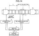
- FIG. 14 is a first diagram illustrating a rail break detection device 4 according to the fifth embodiment of the present invention and structures in the vicinity.
- FIG. 14 illustrates, similarly to FIG. 1 , a vibration sensor 1, which is a first vibration sensor mounted on one of two rails, a vibration sensor 2, which is a second vibration sensor mounted on the other of the two rails at a position facing the vibration sensor 1, a train 3 that is moving along the two rails at a position before the vibration sensors 1 and 2 in the train moving direction, a train 3a that is moving along the two rails at a position ahead of the vibration sensors 1 and 2 in the moving direction, and the rail break detection device 4.
- the vibration sensors 1 and 2 measure vibration of the rails.
- the train 3 is moving along the two rails in the direction toward the vibration sensors 1 and 2
- the train 3a is moving along the two rails in the direction away from the vibration sensors 1 and 2.
- an impulse waveform For the waveform of the vibration caused by the train 3, which is vibration occurring when the train 3 moves toward the vibration sensors 1 and 2, an impulse waveform is used.
- a continuous waveform For the waveform of the vibration caused by the train 3a, which is vibration occurring when the train 3a moves away from the vibration sensors 1 and 2, a continuous waveform is used.
- the rail break detection device 4 determines the similarity between two impulse waveforms, which are obtained by separation by the waveform separation units 41 and 42, by the impulse waveform similarity determination unit 44, and determines the similarity between two continuous waveforms, which are obtained by separation by the waveform separation units 41 and 42, by the continuous waveform similarity determination unit 45. Since the method for determining the similarity of waveforms is described in the first embodiment, the description is not repeated here.
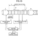
- FIG. 15 is a second diagram illustrating a rail break detection device 4 according to the fifth embodiment of the present invention and structures in the vicinity.
- FIG. 15 illustrates, similarly to FIG. 9 , a vibration sensor 1, which is a first vibration sensor mounted on one of two rails, a vibration sensor 2a, which is a second vibration sensor mounted on the same rail as the rail on which the vibration sensor 1 is mounted, a train 3 that is moving along the two rails at a position before the vibration sensors 1 and 2a in the train moving direction, a train 3a that is moving along the two rails at a position ahead of the vibration sensors 1 and 2a in the moving direction, and the rail break detection device 4.
- the vibration sensors 1 and 2a measure vibration of the rail.
- the train 3 is moving along the two rails in the direction toward the vibration sensors 1 and 2a
- the train 3a is moving along the two rails in the direction away from the vibration sensors 1 and 2a.
- FIG. 15 determination is performed similarly to FIG. 14 , and when two impulse waveforms or two continuous waveforms are dissimilar to each other as a result of the determination, it is determined that a rail break has occurred between the vibration sensor 1 and the vibration sensor 2a. In this manner, a rail break can be detected by using vibration waveforms caused by a plurality of compositions.
- a rail break can be detected by using vibration waveforms caused by a plurality of compositions.
- the present embodiment is also applicable to a radio train control system similarly to the third embodiment, which allows the train 3 to be stopped before passing through the position of a rail break when the rail break is detected.
- vibration is applied a plurality of times by vibration exciters and an average of a plurality of waveforms generated by the plurality of times of application of vibration is calculated in the present embodiment.
- the last application of vibration among the plurality of times of vibration application is performed at a timing when the train 3 is at a position at a distance equal to or longer than the braking distance L from the end of the detection section.
- the present embodiment allows measurement of very weak vibration, which allows the sensors to be arranged at longer intervals.
Landscapes
- Engineering & Computer Science (AREA)
- Physics & Mathematics (AREA)
- General Physics & Mathematics (AREA)
- Mechanical Engineering (AREA)
- Aviation & Aerospace Engineering (AREA)
- Health & Medical Sciences (AREA)
- Biomedical Technology (AREA)
- General Health & Medical Sciences (AREA)
- Train Traffic Observation, Control, And Security (AREA)
- Measurement Of Mechanical Vibrations Or Ultrasonic Waves (AREA)
- Testing Of Devices, Machine Parts, Or Other Structures Thereof (AREA)
Description
- The present invention relates to a rail break detection device.
- Japanese Patent Application
JP 2015-34452 A - Document
US 5 743 495 A shows a redundant sensor system for predicting railway hazards including breaks in each rail, the location of the breaks, and determining when a railway vehicle has a flat wheel. Vibration sensors are distributed along both rails of a railway. Each sensor has a detection band at least within the sensing range of adjacent sensors and it is positioned such that the sensor detects vibration in both the horizontal and vertical axis of the rail. A central processor evaluates the data from these sensors and identifies the rail break, the location of the break, and the flat wheel. - In the related art, however, resonance frequencies of rails are used for detection of a break on a rail. There is thus a problem in which a threshold for determination has to be set for each environment in which rails are laid.
- The present invention has been made in view of the above, and an object thereof is to provide a rail break detection device that can be achieved regardless of the environment in which rails are laid.
- In order to solve the aforementioned problems and achieve the object, there is provided a rail break detection device to which a first output waveform from a first vibration sensor mounted on rails and a second output waveform from a second vibration sensor mounted at a different position from the first vibration sensor are input, the rail break detection device comprising a first waveform separation unit configured to separate the first output waveform of the first vibration sensor and output a first impulse waveform, which is a forced vibration component, and a first continuous waveform, which is a free vibration component; a second waveform separation unit configured to separate the second output waveform of the second vibration sensor and output a second impulse waveform, which is a forced vibration component, and a second continuous waveform, which is a free vibration component; and a waveform similarity determination unit configured to perform at least one of comparison between the first impulse waveform and the second impulse waveform and comparison between the first continuous waveform and the second continuous waveform, and determine similarity between the first output waveform and the second output waveform, wherein a break of rails is detected on the basis of the similarity
- According to the present invention, an effect of providing a rail break detection device that can be achieved regardless of the environment in which rails are laid is produced.
-
-
FIG. 1 is a diagram illustrating a rail break detection device according to a first embodiment and structures in the vicinity. -
FIG. 2 is a diagram illustrating a configuration of the rail break detection device according to the first embodiment, and vibration sensors. -
FIG. 3 is a flowchart illustrating operation of the rail break detection device in the first embodiment. -
FIG. 4 is a flowchart showing only a subset of the features of the invention and illustrating operation of the rail break detection device in a case where a waveform similarity determination unit does not include a continuous waveform similarity determination unit in the first embodiment. -
FIG. 5 is a flowchart showing only a subset of the features of the invention and illustrating operation of the rail break detection device in a case where the waveform similarity determination unit does not include an impulse waveform similarity determination unit in the first embodiment. -
FIG. 6 is a graph illustrating vibration waveforms when no break is present on two rails in the first embodiment. -
FIG. 7 is a graph illustrating vibration waveforms when a break is present on either of two rails in the first embodiment. -
FIG. 8 is a diagram illustrating a typical hardware configuration for implementing the rail break detection device according to the first embodiment. -
FIG. 9 is a diagram illustrating a rail break detection device according to a second embodiment and structures in the vicinity. -
FIG. 10 is a first diagram illustrating a rail break detection device according to a third embodiment and structures in the vicinity. -
FIG. 11 is a second diagram illustrating a rail break detection device according to the third embodiment and structures in the vicinity. -
FIG. 12 is a first diagram illustrating a rail break detection device according to a fourth embodiment and structures in the vicinity. -
FIG. 13 is a second diagram illustrating a rail break detection device according to the fourth embodiment and structures in the vicinity. -
FIG. 14 is a first diagram illustrating a rail break detection device according to a fifth embodiment and structures in the vicinity. -
FIG. 15 is a second diagram illustrating a rail break detection device according to the fifth embodiment and structures in the vicinity. - Rail break detection devices according to certain embodiments of the present invention will be described in detail below with reference to the drawings. Note that the present invention is not limited to the embodiments.
-
FIG. 1 is a diagram illustrating a railbreak detection device 4 according to a first embodiment of the present invention and structures in the vicinity.FIG. 1 illustrates avibration sensor 1, which is a first vibration sensor mounted on one of two rails, avibration sensor 2, which is a second vibration sensor mounted on the other of the two rails at a position facing thevibration sensor 1, atrain 3 that moves along the two rails, and the railbreak detection device 4. Thus, thevibration sensors vibration sensors train 3 is moving along the two rails in the direction toward thevibration sensors -
FIG. 2 is a diagram illustrating a configuration of the railbreak detection device 4 according to the first embodiment, and thevibration sensors break detection device 4 illustrated inFIG. 2 includeswaveform separation units similarity determination unit 43. The waveformsimilarity determination unit 43 includes an impulse waveformsimilarity determination unit 44, and a continuous waveformsimilarity determination unit 45. - The
waveform separation unit 41, which is a first waveform separation unit, separates a waveform output from thevibration sensor 1 into an impulse waveform and a continuous waveform and outputs the impulse waveform and the continuous waveform. The impulse waveform, which is a forced vibration component, will be referred to as a first impulse waveform for convenience sake, and the continuous waveform, which is a free vibration component, will be referred to as a first continuous waveform for convenience sake. Thewaveform separation unit 42, which is a second waveform separation unit, separates a waveform output from thevibration sensor 2 into an impulse waveform and a continuous waveform and outputs the impulse waveform and the continuous waveform. The impulse waveform will be referred to as a second impulse waveform for convenience sake, and the continuous waveform will be referred to as a second continuous waveform for convenience sake. Note that examples of methods for waveform separation include waveform analysis, time frequency analysis, Fourier analysis, wavelet analysis, and sparse analysis. - The waveform
similarity determination unit 43 compares a waveform output from thewaveform separation unit 41 with a waveform output from thewaveform separation unit 42 to determine similarity between the waveforms by using the impulse waveformsimilarity determination unit 44 or the continuous waveformsimilarity determination unit 45, and detects a rail break from the similarity. The waveformsimilarity determination unit 43 compares impulse waveforms by using the impulse waveformsimilarity determination unit 44 when thetrain 3 moves toward thevibration sensors similarity determination unit 45 when thetrain 3 moves away from thevibration sensors train 3 moves toward thevibration sensors train 3 moves away from thevibration sensors - The impulse waveform
similarity determination unit 44 compares the first impulse waveform from thewaveform separation unit 41 with the second impulse waveform from thewaveform separation unit 42 to determine similarity between the impulse waveforms. - The continuous waveform
similarity determination unit 45 compares the first continuous waveform from thewaveform separation unit 41 with the second continuous waveform from thewaveform separation unit 42 to determine similarity between the continuous waveforms. - Note that examples of waveform comparison for determining waveform similarity include a method of comparing root mean square (RMS) values. In a case where RMS values are compared, it is determined that no rail break has occurred when the ratio of the RMS values of vibration strength is within a predetermined threshold range, and it is determined that a rail break has occurred when the ratio of the RMS values of vibration strength is not within the predetermined threshold range. Alternatively, for waveform comparison for determination of waveform similarity, highest values of impulse vibration may be compared or correlation values of time-series data may be compared.
-
FIG. 3 is a flowchart illustrating operation of the railbreak detection device 4 in the first embodiment. First, processing is started, and thewaveform separation units vibration sensors similarity determination unit 44 determines whether or not the two impulse waveforms obtained by the separation are similar to each other (S12). If the impulse waveforms are similar to each other (S12: Yes), the continuous waveformsimilarity determination unit 45 determines whether or not the two continuous waveforms obtained by the separation are similar to each other (S13). If the continuous waveforms are similar to each other (S13: Yes), the waveformsimilarity determination unit 43 determines that no rail break is present (S14), and terminates the processing. If the impulse waveforms are not similar to each other (S12: No) or if the continuous waveforms are not similar to each other (S13: No), the waveformsimilarity determination unit 43 determines that a rail break is present (S15), and terminates the processing. - While the waveform
similarity determination unit 43 illustrated inFIG. 2 includes both of the impulse waveformsimilarity determination unit 44 and the continuous waveformsimilarity determination unit 45, the present invention is not limited thereto, and the waveformsimilarity determination unit 43 may include at least either one of the impulse waveformsimilarity determination unit 44 and the continuous waveformsimilarity determination unit 45. In a case where the waveformsimilarity determination unit 43 does not include the impulse waveformsimilarity determination unit 44 but includes the continuous waveformsimilarity determination unit 45, determination on the similarity of waveforms may be performed when thetrain 3 moves away from thevibration sensors -
FIG. 4 is a flowchart illustrating operation of the railbreak detection device 4 in a case where the waveformsimilarity determination unit 43 does not include the continuous waveformsimilarity determination unit 45 in the first embodiment. First, processing is started, and thewaveform separation units similarity determination unit 44 determines whether or not the extracted impulse waveforms are similar to each other (S12). If the impulse waveforms are similar to each other (S12: Yes), the waveformsimilarity determination unit 43 determines that no rail break is present (S14), and terminates the processing. If the impulse waveforms are not similar to each other (S12: No), the waveformsimilarity determination unit 43 determines that a rail break is present (S15) and terminates the processing. -
FIG. 5 is a flowchart illustrating operation of the railbreak detection device 4 in a case where the waveformsimilarity determination unit 43 does not include the impulse waveformsimilarity determination unit 44 in the first embodiment. First, processing is started, and thewaveform separation units similarity determination unit 45 determines whether or not the extracted continuous waveforms are similar to each other (S13). If the continuous waveforms are similar to each other (S13: Yes), the waveformsimilarity determination unit 43 determines that no rail break is present (S14), and terminates the processing. If the continuous waveforms are not similar to each other (S13: No), the waveformsimilarity determination unit 43 determines that a rail break is present (S15), and terminates the processing. - Although not illustrated in
FIGS. 3 to 5 , output of the result of detection of the presence or absence of a rail break to a railroad map, a display device, a signal, or the like, for example, allows users to know the presence or absence of the rail break. Note that the information given to users through a railroad map, a display device, a signal, or the like may be train availability information instead of the presence or absence of a rail break. -
FIG. 6 is a graph illustrating vibration waveforms when no break is present on two rails in the first embodiment. In addition,FIG. 7 is a graph illustrating vibration waveforms when a break is present on either of two rails in the first embodiment. InFIG. 6 , since no break is present on the two rails, anoutput waveform 51 from thevibration sensor 1 and anoutput waveform 52 from thevibration sensor 2 have waveform profiles similar to each other. InFIG. 7 , since a break is present on a rail on which thevibration sensor 2 is mounted, anoutput waveform 61 from thevibration sensor 1 and anoutput waveform 62 from thevibration sensor 2 have waveform profiles dissimilar to each other. - As described above, according to the present embodiment, waveforms output from a plurality of vibration sensors mounted on two rails at positions facing each other are compared and similarity between the waveforms is determined, so that a difference between the conditions of the two rails is detected without thresholds for determination set for each environment in which rails are laid, which allows detection of a rail break regardless of the environment in which the rails are laid. In addition, an output waveform from a vibration sensor is separated into an impulse waveform and a continuous waveform, which improves accuracy of the detection.
- Note that, in the first embodiment described above, the rail
break detection device 4 may inlude at least a processor, a memory, and an input unit, and operation of each component is implemented by software.FIG. 8 is a diagram illustrating a typical hardware configuration for implementing the railbreak detection device 4 according to the present embodiment. The device illustrated inFIG. 8 includes aprocessor 46, a memory 47, and aninput unit 48. Theprocessor 46 performs computation and control by software by using received data. The memory 47 stores received data, stores data necessary for theprocessor 46 to perform computation and control, and stores software for theprocessor 46 to perform computation and control. Theinput unit 48 inputs output waveforms from thevibration sensors waveform separation units processor 46, the memory 47, and theinput unit 48, and the waveformsimilarity determination unit 43 is implemented by theprocessor 46 and the memory 47. Note that a plurality ofprocessors 46 and a plurality of memories 47 may be provided. - While an embodiment in which two vibration sensors are mounted on different rails has been described in the first embodiment, the present invention is not limited thereto. Two vibration sensors may be mounted on one rail as presented in the present embodiment. Note that, for details in the present embodiment that have already been described in the first embodiment, the first embodiment is to be referred to and redundant description will not be repeated.
-
FIG. 9 is a diagram illustrating a railbreak detection device 4 according to the second embodiment of the present invention and structures in the vicinity.FIG. 9 illustrates thevibration sensor 1, which is the first vibration sensor mounted on one of two rails, avibration sensor 2a, which is the second vibration sensor mounted on the same rail as the rail on which thevibration sensor 1 is mounted, thetrain 3 that moves along the two rails, and the railbreak detection device 4. Thevibration sensors train 3 is moving along the two rails in the direction toward thevibration sensors vibration sensors vibration sensors vibration sensors vibration sensors - As illustrated in
FIG. 9 , in a case where thevibration sensor 1 and thevibration sensor 2a are mounted on one rail as well, theoutput waveform 51 from thevibration sensor 1 and theoutput waveform 52 from thevibration sensor 2a have waveform profiles similar to each other when no break is present on the two rails, and the output waveform from thevibration sensor 1 and the output waveform from thevibration sensor 2a have waveform profiles dissimilar to each other when a break is present on the rail on which thevibration sensor 2a is mounted. Note that, when a break is present on a rail, the output waveform from thevibration sensor 1 and the output waveform from thevibration sensor 2a have waveform profiles dissimilar to each other because the propagation times of propagating waves vary and because the computation of the similarity between waveforms is performed within a predetermined range of propagation time. When no break is present on the rails, the waveform from one of the twovibration sensors - Note that, according to the first and second embodiments, not only a break of a rail but also deterioration of a rail can be detected. Note that deterioration herein refers to a state in which abnormality has occurred inside a rail although no break is observed from the appearance of the rail.
- With a technology using resonance frequencies of rails for rail break detection, a threshold for determination has to be set for each environment in which rails are laid. According to the first and second embodiments, a rail break is detected on the basis of similarity between vibrations of rails at two or more different positions, which is not affected by the material of the rails, the way in which the rails are laid, and the ground on which the rails are laid, and setting of a threshold for detecting a rail break thus need not be set for each environment in which the rails are laid.
- In addition, with a technology of detecting a break of a rail by referring to a current value, a partial break of a rail cannot be detected. According to the first and second embodiments, since current is not used, a partial rail break can be detected. Note that, while the vibration waveform when a rail break is present as illustrated in
FIG. 7 is dissimilar to the vibration waveform when no rail break is present as illustrated inFIG. 6 , a vibration waveform similar to the vibration waveform when no rail break is present as illustrated inFIG. 6 is obtained with a small RMS value when a partial rail break is present. - In addition, with a technology of detecting a break on a rail by comparing image data of left and right rails, image sensors for acquiring image data are vulnerable to dirt and it is envisaged that oil mist and iron powder adhere to image sensors, which requires frequent maintenance work. In the first and second embodiments, such frequent maintenance work is not needed.
- In addition, since vibration information data obtained by measurement by a plurality of vibration sensors are compared, vibration caused by a vehicle crossing a railroad crossing or the like are cancelled out by the comparison. Thus, no false detection occurs owing to the crossing. While cases where two vibration sensors are used have been presented in the first and second embodiments, the present invention is not limited thereto and the number of vibration sensors may be any number larger than one.
- Note that the first and second embodiments are preferably applied to a section including a curve on a railroad. Specifically, it is preferable that any one of sections for detection by the vibration sensors include a curve of a railroad. This is because a rail break is likely to be caused by friction with wheels at a curve on a railroad. Application to a curve with a small radius of curvature on a railroad is particularly preferable.
- Note that the first and second embodiments are also preferably applied to a section including a weld on a railroad. Specifically, it is preferable that any one of sections for detection by the vibration sensors include a weld of a railroad. This is because a rail break is likely to occur at a weld on a railroad.
- The present invention is not limited to the embodiments described in the first and second embodiments, but can also be applied to a radio train control system called communications based train control (CBTC). In the present embodiment, an example of application to CBTC will be described. Note that, for details in the present embodiment that have already been described in the first and second embodiments, the first and second embodiments are to be referred to and redundant description will not be repeated.
-
FIG. 10 is a first diagram illustrating a railbreak detection device 4 according to the third embodiment of the present invention and structures in the vicinity.FIG. 10 illustrates, similarly toFIG. 1 , avibration sensor 1, which is a first vibration sensor mounted on one of two rails, avibration sensor 2, which is a second vibration sensor mounted on the other of the two rails at a position facing thevibration sensor 1, atrain 3 that moves along the two rails, and the railbreak detection device 4. Thevibration sensors train 3 is moving along the two rails in the direction toward thevibration sensors - In
FIG. 10 , the same detection section is set for thevibration sensors vibration sensors vibration sensors vibration sensors vibration sensors vibration sensors vibration sensors - A
ground radio device 6 communicates with a train radio device, which is not illustrated, mounted on thetrain 3 to acquire position information and speed information of thetrain 3, and transmits the acquired information to aground control device 5. The railbreak detection device 4 transmits a result of rail break detection to theground control device 5. - A
central control device 7 is connected with theground control device 5. Thecentral control device 7 receives the position information and the speed information of thetrain 3 and the result of rail break detection from theground control device 5, and controls operation of thetrain 3. In a case where the result of rail break detection indicates presence of a rail break, thecentral control device 7 transmits an instruction to stop thetrain 3 to thetrain 3 via theground control device 5 and theground radio device 6 so as to stop thetrain 3. - In addition, the rail
break detection device 4 detects a rail break in the detection section of thevibration sensors train 3 is moving at a point at a distance equal to or longer than a braking distance L of thetrain 3 before the end of the detection section ofvibration sensors train 3 is coming, and transmits the result of detection to theground control device 5. The braking distance L can be calculated from the speed information of thetrain 3 and a coefficient of rolling friction. In a case where the result of detection indicates presence of a rail break, thecentral control device 7 can stop thetrain 3 before thetrain 3 enters the detection section of thevibration sensors train 3 via theground control device 5 and theground radio device 6. Thus, according to the configuration ofFIG. 10 , a rail break can be detected and thetrain 3 can be stopped before thetrain 3 passes through the position of the rail break. Since the position information and the speed information of thetrain 3 are transmitted to the railbreak detection device 4, the braking distance L of thetrain 3 can be calculated by the railbreak detection device 4. Alternatively, the braking distance L may be calculated by theground control device 5 or thecentral control device 7. -
FIG. 11 is a second diagram illustrating the railbreak detection device 4 according to the third embodiment of the present invention and structures in the vicinity.FIG. 11 illustrates, similarly toFIG. 9 , thevibration sensor 1, which is the first vibration sensor mounted on one of two rails, avibration sensor 2a, which is the second vibration sensor mounted on the same rail as the rail on which thevibration sensor 1 is mounted, thetrain 3 that moves along the two rails, and the railbreak detection device 4. Thevibration sensors train 3 is moving along the two rails in the direction toward thevibration sensors - In
FIG. 11 , a section between thevibration sensor 1 and thevibration sensor 2a is set as the detection section. Specifically, the positions at which thevibration sensor 1 and thevibration sensor 2a are installed are ends of the detection section, and the distance between thevibration sensor 1 and thevibration sensor 2a is a distance within which thevibration sensors vibration sensors vibration sensor 1, so that adjacent detection sections of vibration sensors are arranged continuously similarly toFIG. 10 , which allows rail break detection without leaving a section in which a rail break cannot be detected on the rails. - Similarly to
FIG. 10 , theground radio device 6 communicates with the train radio device, which is not illustrated, mounted on thetrain 3 to acquire position information and speed information of thetrain 3, and transmits the acquired information to theground control device 5. The railbreak detection device 4 transmits a result of rail break detection to theground control device 5. - The
central control device 7 is connected with theground control device 5. Thecentral control device 7 receives the position information and the speed information of thetrain 3 and the result of rail break detection from theground control device 5, and controls operation of thetrain 3. In a case where the result of rail break detection indicates presence of a rail break, thecentral control device 7 transmits an instruction to stop thetrain 3 to thetrain 3 via theground control device 5 and theground radio device 6 so as to stop thetrain 3. - In addition, the rail
break detection device 4 detects a rail break in the detection section defined by thevibration sensor 1 and thevibration sensor 2a at a timing when thetrain 3 is moving at a point at a distance equal to or more than the braking distance L of thetrain 3 before thevibration sensor 2a, and transmits the result of detection to theground control device 5. In a case where the result of detection indicates presence of a rail break, thecentral control device 7 can stop thetrain 3 before thetrain 3 enters the detection section defined by thevibration sensor 1 and thevibration sensor 2a by performing control to stop thetrain 3 via theground control device 5 and theground radio device 6. Thus, according to the configuration ofFIG. 11 , a rail break can be detected and thetrain 3 can be stopped before thetrain 3 passes through the position of the rail break. Since the position information and the speed information of thetrain 3 are transmitted to the railbreak detection device 4, the braking distance L of thetrain 3 can be calculated by the railbreak detection device 4. Alternatively, the braking distance L may be calculated by theground control device 5 or thecentral control device 7. - As described above, according to the configuration of the present embodiment, a rail break can be detected and a train can be stopped before the train passes through the position of the rail break.
- In a case where vibration caused by a moving train is used as a vibration source of rail vibration or a case where vibration excited by a moving train such as a case where the train speed is low, a rail break may not be detected. Thus, in the present invention, a vibration exciter may be provided adjacent to a vibration sensor. In the present embodiment, an embodiment in which vibration exciters are provided adjacent to the vibration sensors in the configuration of the third embodiment will be described. Note that, for details in the present embodiment that have already been described in the first to third embodiments, the first to third embodiments are to be referred to and redundant description will not be repeated. While the embodiment in which vibration exciters are provided adjacent to the vibration sensors in the configuration of the third embodiment will be described in the present embodiment, the configuration of the present embodiment may be combined with the first or second embodiment.
-
FIG. 12 is a first diagram illustrating a railbreak detection device 4 according to the fourth embodiment of the present invention and structures in the vicinity.FIG. 12 illustrates, similarly toFIG. 1 , avibration sensor 1, which is a first vibration sensor mounted on one of two rails, avibration sensor 2, which is a second vibration sensor mounted on the other of the two rails at a position facing thevibration sensor 1, atrain 3 that moves along the two rails, and the railbreak detection device 4. Thevibration sensors train 3 is moving along the two rails in the direction toward thevibration sensors vibration exciter 71 is provided before thevibration sensor 1 in the moving direction of thetrain 3, and avibration exciter 72 is provided before thevibration sensor 2 in the moving direction of thetrain 3. - The
vibration exciters vibration exciters train 3 is at a position at a distance equal to or longer than the braking distance L from the end of the detection section in accordance with an instruction from thecentral control device 7. The railbreak detection device 4 detects a rail break by using the vibrations caused by thevibration exciters vibration exciters -
FIG. 13 is a second diagram illustrating a railbreak detection device 4 according to the fourth embodiment of the present invention and structures in the vicinity.FIG. 13 illustrates, similarly toFIG. 9 , thevibration sensor 1, which is the first vibration sensor mounted on one of two rails, avibration sensor 2a, which is the second vibration sensor mounted on the same rail as the rail on which thevibration sensor 1 is mounted, thetrain 3 that moves along the two rails, and the railbreak detection device 4. Thevibration sensors train 3 is moving along the two rails in the direction toward thevibration sensors vibration exciter 71 is provided before thevibration sensor 1 in the moving direction of thetrain 3, and avibration exciter 72a is provided before thevibration sensor 2a in the moving direction of thetrain 3. - Similarly to
FIG. 12 , thevibration exciters vibration exciters train 3 is at a position at a distance equal to or longer than the braking distance L from the end of the detection section in accordance with an instruction from thecentral control device 7 via theground control device 5. The railbreak detection device 4 detects a rail break by using the vibrations caused by thevibration exciters - While the
vibration exciters central control device 7 in the present embodiment, the present invention is not limited thereto. The railbreak detection device 4 or theground control device 5 may output an instruction to apply vibration to thevibration exciters - While the
vibration exciters vibration sensors train 3 moves in one direction inFIGS. 12 and13 , the present invention is not limited thereto. In a case where a railroad is a single track line, for example, vibration exciters may be provided on respective sides of a vibration sensor since the moving direction of the train is switched. - As described above, according to the configuration of the present embodiment, even in a case where vibration excited by a moving train such as a case where the train speed is low, a rail break can be detected and a train can be stopped before the train passes through the position of the rail break by using vibration applied by a vibration exciter.
- Note that, according to the fourth embodiment, even in a case where no train moves on the rails during non-service hours, a rail break can be detected by using vibration applied by a vibration exciter.
- While only the
train 3 is illustrated on the rails and embodiments in which a rail break is detected by using vibration caused by thetrain 3 have been described in the first to fourth embodiments, the present invention is not limited thereto. In the present invention, a rail break can also be detected by using both of vibration caused by atrain 3 present before a vibration sensor in the moving direction of the train and vibration caused by atrain 3a present ahead of the vibration sensor in the moving direction. Note that, for details in the present embodiment that have already been described in the first to fourth embodiments, the first to fourth embodiments are to be referred to and redundant description will not be repeated. Note that, in the present embodiment, an embodiment in which atrain 3 is present before the vibration sensors in the train moving direction in the configuration of the third embodiment and atrain 3a is present ahead of the vibration sensors in the configuration of the third embodiment will be described. -
FIG. 14 is a first diagram illustrating a railbreak detection device 4 according to the fifth embodiment of the present invention and structures in the vicinity.FIG. 14 illustrates, similarly toFIG. 1 , avibration sensor 1, which is a first vibration sensor mounted on one of two rails, avibration sensor 2, which is a second vibration sensor mounted on the other of the two rails at a position facing thevibration sensor 1, atrain 3 that is moving along the two rails at a position before thevibration sensors train 3a that is moving along the two rails at a position ahead of thevibration sensors break detection device 4. Thevibration sensors train 3 is moving along the two rails in the direction toward thevibration sensors train 3a is moving along the two rails in the direction away from thevibration sensors - For the waveform of the vibration caused by the
train 3, which is vibration occurring when thetrain 3 moves toward thevibration sensors train 3a, which is vibration occurring when thetrain 3a moves away from thevibration sensors break detection device 4 determines the similarity between two impulse waveforms, which are obtained by separation by thewaveform separation units similarity determination unit 44, and determines the similarity between two continuous waveforms, which are obtained by separation by thewaveform separation units similarity determination unit 45. Since the method for determining the similarity of waveforms is described in the first embodiment, the description is not repeated here. When the two impulse waveforms are dissimilar to each other as a result of the determination, it is determined that a rail break has occurred between thetrain 3 and thevibration sensors train 3a and thevibration sensors -
FIG. 15 is a second diagram illustrating a railbreak detection device 4 according to the fifth embodiment of the present invention and structures in the vicinity.FIG. 15 illustrates, similarly toFIG. 9 , avibration sensor 1, which is a first vibration sensor mounted on one of two rails, avibration sensor 2a, which is a second vibration sensor mounted on the same rail as the rail on which thevibration sensor 1 is mounted, atrain 3 that is moving along the two rails at a position before thevibration sensors train 3a that is moving along the two rails at a position ahead of thevibration sensors break detection device 4. Thevibration sensors train 3 is moving along the two rails in the direction toward thevibration sensors train 3a is moving along the two rails in the direction away from thevibration sensors - In
FIG. 15 , determination is performed similarly toFIG. 14 , and when two impulse waveforms or two continuous waveforms are dissimilar to each other as a result of the determination, it is determined that a rail break has occurred between thevibration sensor 1 and thevibration sensor 2a. In this manner, a rail break can be detected by using vibration waveforms caused by a plurality of compositions. - According to the present embodiment, a rail break can be detected by using vibration waveforms caused by a plurality of compositions. In addition, the present embodiment is also applicable to a radio train control system similarly to the third embodiment, which allows the
train 3 to be stopped before passing through the position of a rail break when the rail break is detected. - While an embodiment in which a rail break is detected by using vibration generated by applying vibration to the rails by the vibration exciters has been described in the fourth embodiment, vibration is applied a plurality of times by vibration exciters and an average of a plurality of waveforms generated by the plurality of times of application of vibration is calculated in the present embodiment.
- Note that the last application of vibration among the plurality of times of vibration application is performed at a timing when the
train 3 is at a position at a distance equal to or longer than the braking distance L from the end of the detection section. - The present embodiment allows measurement of very weak vibration, which allows the sensors to be arranged at longer intervals.
- The configurations presented in the embodiments above are examples of the present invention, which can be combined with other known technologies or can be partly omitted or modified without departing from the scope of the present invention as defined by the appended claims.
- 1, 2, 2a vibration sensor; 3, 3a train; 4 rail break detection device; 5 ground control device; 6 ground radio device; 7 central control device; 41, 42 waveform separation unit; 43 waveform similarity determination unit; 44 impulse waveform similarity determination unit; 45 continuous waveform similarity determination unit; 46 processor; 47 memory; 48 input unit; 51, 52, 61, 62 output waveform; 71, 72, 72a vibration exciter.
Claims (9)
- A rail break detection device (4) to which a first output waveform from a first vibration sensor (1) mounted on rails and a second output waveform from a second vibration sensor (2) mounted at a different position from the first vibration sensor (1) are input, the rail break detection device (4) comprising:a first waveform separation unit (41) configured to separate the first output waveform of the first vibration sensor (1) and output a first impulse waveform, which is a forced vibration component, and a first continuous waveform, which is a free vibration component;a second waveform separation unit (42) configured to separate the second output waveform of the second vibration sensor (2) and output a second impulse waveform, which is a forced vibration component, and a second continuous waveform, which is a free vibration component; anda waveform similarity determination unit (43) configured to perform at least one of comparison between the first impulse waveform and the second impulse waveform and comparison between the first continuous waveform and the second continuous waveform, and determine similarity between the first output waveform and the second output waveform, whereina break of rails is detected on the basis of the similarity.
- The rail break detection device (4) according to claim 1, wherein the first vibration sensor (1) and the second vibration sensor (2) are mounted on different rails parallel to each other.
- The rail break detection device (4) according to claim 1, wherein the first vibration sensor (1) is mounted on a same rail as the second vibration sensor (2).
- The rail break detection device (4) according to claim 1, wherein a detection section of the first and second vibration sensors (1, 2) includes a curve of a railroad.
- The rail break detection device (4) according to claim 1, wherein a detection section of the first and second vibration sensors (1, 2) includes a weld of a railroad.
- The rail break detection device (4) according to claim 1, wherein the rail break detection device (4) is configured to detect a break on the rails before a train (3) moving along the rails enters a detection section of the first and second vibration sensors (1, 2) on the basis of position information and speed information of the train (3).
- The rail break detection device (4) according to claim 1, wherein a vibration exciter (71, 72) is provided before the first and second vibration sensors (1, 2) in a moving direction of a train.
- The rail break detection device (4) according to claim 1, whereinwhen the first impulse waveform and the second impulse waveform are dissimilar to each other, the rail break detection device (4) is configured to detect that a rail break is present between a train (3) moving toward the first and second vibration sensors (1, 2) and the first and second vibration sensors (1, 2), andwhen the first continuous waveform and the second continuous waveform are dissimilar to each other, the rail break detection device (4) is configured to detect that a rail break is present between a train (3a) moving away from the first and second vibration sensors (1, 2) and the first and second vibration sensors (1, 2).
- The rail break detection device (4) according to claim 7, whereinthe vibration exciter (71, 72) is configured to apply vibration a plurality of times to a rail on which the vibration exciter (71, 72) is mounted,an average of a plurality of vibration waveforms obtained by the first vibration sensor (1) through a plurality of times of application of vibration is used as an output waveform of the first vibration sensor (1), andan average of a plurality of vibration waveforms obtained by the second vibration sensor (2) through a plurality of times of application of vibration is used as an output waveform of the second vibration sensor (2).
Applications Claiming Priority (2)
| Application Number | Priority Date | Filing Date | Title |
|---|---|---|---|
| PCT/JP2016/061033 WO2017175276A1 (en) | 2016-04-04 | 2016-04-04 | Rail breakage detection device |
| PCT/JP2017/014136 WO2017175768A1 (en) | 2016-04-04 | 2017-04-04 | Rail breakage detection device |
Publications (3)
| Publication Number | Publication Date |
|---|---|
| EP3441280A1 EP3441280A1 (en) | 2019-02-13 |
| EP3441280A4 EP3441280A4 (en) | 2019-05-15 |
| EP3441280B1 true EP3441280B1 (en) | 2021-12-29 |
Family
ID=60000982
Family Applications (1)
| Application Number | Title | Priority Date | Filing Date |
|---|---|---|---|
| EP17779146.4A Not-in-force EP3441280B1 (en) | 2016-04-04 | 2017-04-04 | Rail breakage detection device |
Country Status (4)
| Country | Link |
|---|---|
| US (1) | US11572088B2 (en) |
| EP (1) | EP3441280B1 (en) |
| JP (1) | JP6490302B2 (en) |
| WO (2) | WO2017175276A1 (en) |
Families Citing this family (9)
| Publication number | Priority date | Publication date | Assignee | Title |
|---|---|---|---|---|
| WO2017175276A1 (en) * | 2016-04-04 | 2017-10-12 | 三菱電機株式会社 | Rail breakage detection device |
| US11433929B2 (en) * | 2017-04-04 | 2022-09-06 | Loram Technologies, Inc. | Railroad track guidance systems and methods |
| BR102017026315B1 (en) * | 2017-12-06 | 2023-05-16 | Rumo Logística Operadora Multimodal S.A | METHOD FOR RAILWAY BREAKAGE DETECTION, RAILWAY TRACK BREAKAGE DETECTION SYSTEM AND RAILWAY BREAKAGE DEVICE |
| FR3105148B1 (en) * | 2019-12-23 | 2023-10-06 | Commissariat Energie Atomique | SYSTEM AND METHOD FOR DETECTING A DEFECT IN A RAIL OF A RAILWAY |
| SE545220C2 (en) * | 2020-06-03 | 2023-05-30 | Luleaa Tekniska Univ Avd Foer Drift Och Underhaallsteknik | Method for measuring damage to track switches and train wheels in switching devices |
| FR3114206B1 (en) * | 2020-09-11 | 2023-01-06 | Commissariat Energie Atomique | System and method for detecting defects in elongated waveguides. |
| CN112945372A (en) * | 2021-01-26 | 2021-06-11 | 深圳中慧轨道智能科技有限公司 | Sliding plate fracture monitoring devices |
| KR102671392B1 (en) * | 2023-04-28 | 2024-05-31 | 한국철도기술연구원 | Complex type rail fracture decision system and method for deciding rail fracture using the same |
| CN117184175A (en) * | 2023-08-22 | 2023-12-08 | 北京交通大学 | Track breakage detection method and system based on train self-excitation and wireless IoT technology |
Family Cites Families (21)
| Publication number | Priority date | Publication date | Assignee | Title |
|---|---|---|---|---|
| DE4116650A1 (en) | 1991-05-22 | 1992-11-26 | Gerd R Dipl Ing Wetzler | Detecting rail openings in continuously welded sections of railway track - transmitting sound along rails to microphone and logically combining electrical pulses detected from both rails |
| JPH07333054A (en) * | 1994-06-06 | 1995-12-22 | West Japan Railway Co | Crack sensor for rail |
| US5743495A (en) * | 1997-02-12 | 1998-04-28 | General Electric Company | System for detecting broken rails and flat wheels in the presence of trains |
| JPH11118770A (en) * | 1997-10-20 | 1999-04-30 | Tokimec Inc | Ultrasonic flaw-detecting method and device |
| GB0104688D0 (en) * | 2001-02-26 | 2001-04-11 | Roke Manor Research | Active rail health monitoring system |
| US6911914B2 (en) * | 2002-03-29 | 2005-06-28 | General Electric Company | Method and apparatus for detecting hot rail car surfaces |
| US6951132B2 (en) * | 2003-06-27 | 2005-10-04 | General Electric Company | Rail and train monitoring system and method |
| WO2006030786A1 (en) * | 2004-09-13 | 2006-03-23 | Nsk Ltd. | Abnormality diagnosis device and abnormality diagnosis method |
| US20060076461A1 (en) * | 2004-10-12 | 2006-04-13 | General Electric Company | System and method for self powered wayside railway signaling and sensing |
| JP4569437B2 (en) * | 2005-08-31 | 2010-10-27 | 日本精工株式会社 | Abnormality diagnosis device |
| JP4803382B2 (en) * | 2006-12-15 | 2011-10-26 | 国立大学法人名古屋大学 | Vibration characteristic estimation method and vibration characteristic estimation apparatus |
| JP2010096541A (en) * | 2008-10-14 | 2010-04-30 | Thk Co Ltd | Damage inspection device, and method |
| US20120279308A1 (en) * | 2011-05-04 | 2012-11-08 | Fbs, Inc. | Elastic wave rail defect detection system |
| WO2013152018A1 (en) * | 2012-04-06 | 2013-10-10 | The Regents Of The University Of California | Air-coupled ultrasonic inspection of rails |
| CZ23860U1 (en) * | 2012-04-18 | 2012-05-21 | Jaluvka@Otakar | Device to monitor, detect and diagnose railway vehicles of ground, underground as well as overhead railways and components thereof on the run |
| WO2014027977A1 (en) * | 2012-08-14 | 2014-02-20 | ENEKOM ENERJI EKOLOJI BILIŞIM VE MUHENDISLIK SANAYI TICARET LIMITED ŞlRKETI | A method for the detection of rail fractures and cracks |
| JP6297280B2 (en) | 2013-08-09 | 2018-03-20 | 日本信号株式会社 | Rail break detection device |
| JP6465034B2 (en) * | 2013-12-27 | 2019-02-06 | 日本電気株式会社 | Signal analysis apparatus, excitation force measurement system, signal analysis method, and signal analysis program |
| CN107406090B (en) * | 2015-01-16 | 2020-11-20 | 国际电子机械公司 | Abnormal vehicle dynamic detection |
| WO2017175276A1 (en) * | 2016-04-04 | 2017-10-12 | 三菱電機株式会社 | Rail breakage detection device |
| CA3200604A1 (en) * | 2017-03-24 | 2018-09-24 | Canadian Pacific Railway Company | Condition based maintenance of railcar roller bearings using predictive wayside alerts based on acoustic bearing detector measurements |
-
2016
- 2016-04-04 WO PCT/JP2016/061033 patent/WO2017175276A1/en not_active Ceased
-
2017
- 2017-04-04 JP JP2018510619A patent/JP6490302B2/en not_active Expired - Fee Related
- 2017-04-04 WO PCT/JP2017/014136 patent/WO2017175768A1/en not_active Ceased
- 2017-04-04 EP EP17779146.4A patent/EP3441280B1/en not_active Not-in-force
- 2017-04-04 US US16/079,696 patent/US11572088B2/en active Active
Also Published As
| Publication number | Publication date |
|---|---|
| WO2017175768A1 (en) | 2017-10-12 |
| WO2017175276A1 (en) | 2017-10-12 |
| US20190300032A1 (en) | 2019-10-03 |
| JPWO2017175768A1 (en) | 2018-08-09 |
| JP6490302B2 (en) | 2019-03-27 |
| US11572088B2 (en) | 2023-02-07 |
| EP3441280A4 (en) | 2019-05-15 |
| EP3441280A1 (en) | 2019-02-13 |
Similar Documents
| Publication | Publication Date | Title |
|---|---|---|
| EP3441280B1 (en) | Rail breakage detection device | |
| EP3050774B2 (en) | Railway systems using acoustic monitoring | |
| RU2365517C2 (en) | Rail and train monitoring system and method thereof | |
| CN106662483B (en) | Anomaly detection in a rail wheel set | |
| US10850754B2 (en) | Distributed fibre optic sensing for monitoring rail networks | |
| US12116030B2 (en) | Methods and systems for monitoring a transportation path with acoustic or vibration sensing | |
| EP3441279A1 (en) | Rail breakage detection device | |
| WO2013125110A1 (en) | Obstacle determination device | |
| KR102534694B1 (en) | Method for train localization and train integrity verification using distributed acoustic sensing technology | |
| US20220032981A1 (en) | Railroad monitoring system, railroad monitoring device, railroad monitoring method, and non-transitory computer-readable medium | |
| JP2016016731A (en) | Train position detection system and train position detection method, and program | |
| JP6851111B2 (en) | Railroad crossing obstacle detection device | |
| JP6617881B2 (en) | Train passage determination system, train passage determination method, and train passage determination program | |
| JP6365633B2 (en) | Vehicle length estimation device, traffic control system, vehicle length estimation method, and vehicle length estimation program | |
| KR20200050012A (en) | Wheel detecting system for detecting position of the railway car using piezoelectric element and method thereof | |
| JP2025165263A (en) | Wheel tread inspection device, wheel tread inspection system, and wheel tread inspection method | |
| JP2016014537A (en) | Sensor | |
| KR20230085521A (en) | railway and train monitoring system | |
| KR20230065491A (en) | Apparatus and method for calculating traffic information through radar and loop detection complex sensing | |
| TH2001004342A (en) | Rail system fault detectors and methods thereof | |
| TH2001004728A (en) | A set of abnormality detectors for the rail system. |
Legal Events
| Date | Code | Title | Description |
|---|---|---|---|
| STAA | Information on the status of an ep patent application or granted ep patent |
Free format text: STATUS: THE INTERNATIONAL PUBLICATION HAS BEEN MADE |
|
| PUAI | Public reference made under article 153(3) epc to a published international application that has entered the european phase |
Free format text: ORIGINAL CODE: 0009012 |
|
| STAA | Information on the status of an ep patent application or granted ep patent |
Free format text: STATUS: REQUEST FOR EXAMINATION WAS MADE |
|
| 17P | Request for examination filed |
Effective date: 20180928 |
|
| AK | Designated contracting states |
Kind code of ref document: A1 Designated state(s): AL AT BE BG CH CY CZ DE DK EE ES FI FR GB GR HR HU IE IS IT LI LT LU LV MC MK MT NL NO PL PT RO RS SE SI SK SM TR |
|
| AX | Request for extension of the european patent |
Extension state: BA ME |
|
| A4 | Supplementary search report drawn up and despatched |
Effective date: 20190416 |
|
| RIC1 | Information provided on ipc code assigned before grant |
Ipc: G01H 1/00 20060101ALI20190410BHEP Ipc: B61L 23/04 20060101AFI20190410BHEP Ipc: B61L 27/00 20060101ALI20190410BHEP Ipc: G01M 7/02 20060101ALI20190410BHEP |
|
| DAV | Request for validation of the european patent (deleted) | ||
| DAX | Request for extension of the european patent (deleted) | ||
| RIC1 | Information provided on ipc code assigned before grant |
Ipc: B61L 23/04 20060101AFI20201223BHEP Ipc: G01H 1/00 20060101ALI20201223BHEP Ipc: G01M 7/02 20060101ALI20201223BHEP Ipc: B61L 27/00 20060101ALI20201223BHEP |
|
| GRAP | Despatch of communication of intention to grant a patent |
Free format text: ORIGINAL CODE: EPIDOSNIGR1 |
|
| STAA | Information on the status of an ep patent application or granted ep patent |
Free format text: STATUS: GRANT OF PATENT IS INTENDED |
|
| INTG | Intention to grant announced |
Effective date: 20210129 |
|
| GRAJ | Information related to disapproval of communication of intention to grant by the applicant or resumption of examination proceedings by the epo deleted |
Free format text: ORIGINAL CODE: EPIDOSDIGR1 |
|
| STAA | Information on the status of an ep patent application or granted ep patent |
Free format text: STATUS: REQUEST FOR EXAMINATION WAS MADE |
|
| INTC | Intention to grant announced (deleted) | ||
| GRAP | Despatch of communication of intention to grant a patent |
Free format text: ORIGINAL CODE: EPIDOSNIGR1 |
|
| STAA | Information on the status of an ep patent application or granted ep patent |
Free format text: STATUS: GRANT OF PATENT IS INTENDED |
|
| INTG | Intention to grant announced |
Effective date: 20210709 |
|
| GRAS | Grant fee paid |
Free format text: ORIGINAL CODE: EPIDOSNIGR3 |
|
| GRAA | (expected) grant |
Free format text: ORIGINAL CODE: 0009210 |
|
| STAA | Information on the status of an ep patent application or granted ep patent |
Free format text: STATUS: THE PATENT HAS BEEN GRANTED |
|
| AK | Designated contracting states |
Kind code of ref document: B1 Designated state(s): AL AT BE BG CH CY CZ DE DK EE ES FI FR GB GR HR HU IE IS IT LI LT LU LV MC MK MT NL NO PL PT RO RS SE SI SK SM TR |
|
| REG | Reference to a national code |
Ref country code: GB Ref legal event code: FG4D |
|
| REG | Reference to a national code |
Ref country code: CH Ref legal event code: EP |
|
| REG | Reference to a national code |
Ref country code: AT Ref legal event code: REF Ref document number: 1458482 Country of ref document: AT Kind code of ref document: T Effective date: 20220115 |
|
| REG | Reference to a national code |
Ref country code: IE Ref legal event code: FG4D |
|
| REG | Reference to a national code |
Ref country code: DE Ref legal event code: R096 Ref document number: 602017051610 Country of ref document: DE |
|
| REG | Reference to a national code |
Ref country code: LT Ref legal event code: MG9D |
|
| PG25 | Lapsed in a contracting state [announced via postgrant information from national office to epo] |
Ref country code: RS Free format text: LAPSE BECAUSE OF FAILURE TO SUBMIT A TRANSLATION OF THE DESCRIPTION OR TO PAY THE FEE WITHIN THE PRESCRIBED TIME-LIMIT Effective date: 20211229 Ref country code: LT Free format text: LAPSE BECAUSE OF FAILURE TO SUBMIT A TRANSLATION OF THE DESCRIPTION OR TO PAY THE FEE WITHIN THE PRESCRIBED TIME-LIMIT Effective date: 20211229 Ref country code: FI Free format text: LAPSE BECAUSE OF FAILURE TO SUBMIT A TRANSLATION OF THE DESCRIPTION OR TO PAY THE FEE WITHIN THE PRESCRIBED TIME-LIMIT Effective date: 20211229 Ref country code: BG Free format text: LAPSE BECAUSE OF FAILURE TO SUBMIT A TRANSLATION OF THE DESCRIPTION OR TO PAY THE FEE WITHIN THE PRESCRIBED TIME-LIMIT Effective date: 20220329 |
|
| REG | Reference to a national code |
Ref country code: NL Ref legal event code: MP Effective date: 20211229 |
|
| REG | Reference to a national code |
Ref country code: AT Ref legal event code: MK05 Ref document number: 1458482 Country of ref document: AT Kind code of ref document: T Effective date: 20211229 |
|
| PG25 | Lapsed in a contracting state [announced via postgrant information from national office to epo] |
Ref country code: SE Free format text: LAPSE BECAUSE OF FAILURE TO SUBMIT A TRANSLATION OF THE DESCRIPTION OR TO PAY THE FEE WITHIN THE PRESCRIBED TIME-LIMIT Effective date: 20211229 Ref country code: NO Free format text: LAPSE BECAUSE OF FAILURE TO SUBMIT A TRANSLATION OF THE DESCRIPTION OR TO PAY THE FEE WITHIN THE PRESCRIBED TIME-LIMIT Effective date: 20220329 Ref country code: LV Free format text: LAPSE BECAUSE OF FAILURE TO SUBMIT A TRANSLATION OF THE DESCRIPTION OR TO PAY THE FEE WITHIN THE PRESCRIBED TIME-LIMIT Effective date: 20211229 Ref country code: HR Free format text: LAPSE BECAUSE OF FAILURE TO SUBMIT A TRANSLATION OF THE DESCRIPTION OR TO PAY THE FEE WITHIN THE PRESCRIBED TIME-LIMIT Effective date: 20211229 Ref country code: GR Free format text: LAPSE BECAUSE OF FAILURE TO SUBMIT A TRANSLATION OF THE DESCRIPTION OR TO PAY THE FEE WITHIN THE PRESCRIBED TIME-LIMIT Effective date: 20220330 |
|
| PG25 | Lapsed in a contracting state [announced via postgrant information from national office to epo] |
Ref country code: NL Free format text: LAPSE BECAUSE OF FAILURE TO SUBMIT A TRANSLATION OF THE DESCRIPTION OR TO PAY THE FEE WITHIN THE PRESCRIBED TIME-LIMIT Effective date: 20211229 |
|
| PG25 | Lapsed in a contracting state [announced via postgrant information from national office to epo] |
Ref country code: SM Free format text: LAPSE BECAUSE OF FAILURE TO SUBMIT A TRANSLATION OF THE DESCRIPTION OR TO PAY THE FEE WITHIN THE PRESCRIBED TIME-LIMIT Effective date: 20211229 Ref country code: SK Free format text: LAPSE BECAUSE OF FAILURE TO SUBMIT A TRANSLATION OF THE DESCRIPTION OR TO PAY THE FEE WITHIN THE PRESCRIBED TIME-LIMIT Effective date: 20211229 Ref country code: RO Free format text: LAPSE BECAUSE OF FAILURE TO SUBMIT A TRANSLATION OF THE DESCRIPTION OR TO PAY THE FEE WITHIN THE PRESCRIBED TIME-LIMIT Effective date: 20211229 Ref country code: PT Free format text: LAPSE BECAUSE OF FAILURE TO SUBMIT A TRANSLATION OF THE DESCRIPTION OR TO PAY THE FEE WITHIN THE PRESCRIBED TIME-LIMIT Effective date: 20220429 Ref country code: ES Free format text: LAPSE BECAUSE OF FAILURE TO SUBMIT A TRANSLATION OF THE DESCRIPTION OR TO PAY THE FEE WITHIN THE PRESCRIBED TIME-LIMIT Effective date: 20211229 Ref country code: EE Free format text: LAPSE BECAUSE OF FAILURE TO SUBMIT A TRANSLATION OF THE DESCRIPTION OR TO PAY THE FEE WITHIN THE PRESCRIBED TIME-LIMIT Effective date: 20211229 Ref country code: CZ Free format text: LAPSE BECAUSE OF FAILURE TO SUBMIT A TRANSLATION OF THE DESCRIPTION OR TO PAY THE FEE WITHIN THE PRESCRIBED TIME-LIMIT Effective date: 20211229 |
|
| PG25 | Lapsed in a contracting state [announced via postgrant information from national office to epo] |
Ref country code: PL Free format text: LAPSE BECAUSE OF FAILURE TO SUBMIT A TRANSLATION OF THE DESCRIPTION OR TO PAY THE FEE WITHIN THE PRESCRIBED TIME-LIMIT Effective date: 20211229 Ref country code: AT Free format text: LAPSE BECAUSE OF FAILURE TO SUBMIT A TRANSLATION OF THE DESCRIPTION OR TO PAY THE FEE WITHIN THE PRESCRIBED TIME-LIMIT Effective date: 20211229 |
|
| PG25 | Lapsed in a contracting state [announced via postgrant information from national office to epo] |
Ref country code: IS Free format text: LAPSE BECAUSE OF FAILURE TO SUBMIT A TRANSLATION OF THE DESCRIPTION OR TO PAY THE FEE WITHIN THE PRESCRIBED TIME-LIMIT Effective date: 20220429 |
|
| REG | Reference to a national code |
Ref country code: DE Ref legal event code: R097 Ref document number: 602017051610 Country of ref document: DE |
|
| PG25 | Lapsed in a contracting state [announced via postgrant information from national office to epo] |
Ref country code: DK Free format text: LAPSE BECAUSE OF FAILURE TO SUBMIT A TRANSLATION OF THE DESCRIPTION OR TO PAY THE FEE WITHIN THE PRESCRIBED TIME-LIMIT Effective date: 20211229 Ref country code: AL Free format text: LAPSE BECAUSE OF FAILURE TO SUBMIT A TRANSLATION OF THE DESCRIPTION OR TO PAY THE FEE WITHIN THE PRESCRIBED TIME-LIMIT Effective date: 20211229 |
|
| PLBE | No opposition filed within time limit |
Free format text: ORIGINAL CODE: 0009261 |
|
| STAA | Information on the status of an ep patent application or granted ep patent |
Free format text: STATUS: NO OPPOSITION FILED WITHIN TIME LIMIT |
|
| REG | Reference to a national code |
Ref country code: CH Ref legal event code: PL |
|
| 26N | No opposition filed |
Effective date: 20220930 |
|
| GBPC | Gb: european patent ceased through non-payment of renewal fee |
Effective date: 20220404 |
|
| REG | Reference to a national code |
Ref country code: BE Ref legal event code: MM Effective date: 20220430 |
|
| PG25 | Lapsed in a contracting state [announced via postgrant information from national office to epo] |
Ref country code: MC Free format text: LAPSE BECAUSE OF FAILURE TO SUBMIT A TRANSLATION OF THE DESCRIPTION OR TO PAY THE FEE WITHIN THE PRESCRIBED TIME-LIMIT Effective date: 20211229 Ref country code: LU Free format text: LAPSE BECAUSE OF NON-PAYMENT OF DUE FEES Effective date: 20220404 Ref country code: LI Free format text: LAPSE BECAUSE OF NON-PAYMENT OF DUE FEES Effective date: 20220430 Ref country code: GB Free format text: LAPSE BECAUSE OF NON-PAYMENT OF DUE FEES Effective date: 20220404 Ref country code: FR Free format text: LAPSE BECAUSE OF NON-PAYMENT OF DUE FEES Effective date: 20220430 Ref country code: CH Free format text: LAPSE BECAUSE OF NON-PAYMENT OF DUE FEES Effective date: 20220430 |
|
| PG25 | Lapsed in a contracting state [announced via postgrant information from national office to epo] |
Ref country code: SI Free format text: LAPSE BECAUSE OF FAILURE TO SUBMIT A TRANSLATION OF THE DESCRIPTION OR TO PAY THE FEE WITHIN THE PRESCRIBED TIME-LIMIT Effective date: 20211229 Ref country code: BE Free format text: LAPSE BECAUSE OF NON-PAYMENT OF DUE FEES Effective date: 20220430 |
|
| PG25 | Lapsed in a contracting state [announced via postgrant information from national office to epo] |
Ref country code: IE Free format text: LAPSE BECAUSE OF NON-PAYMENT OF DUE FEES Effective date: 20220404 |
|
| PG25 | Lapsed in a contracting state [announced via postgrant information from national office to epo] |
Ref country code: IT Free format text: LAPSE BECAUSE OF FAILURE TO SUBMIT A TRANSLATION OF THE DESCRIPTION OR TO PAY THE FEE WITHIN THE PRESCRIBED TIME-LIMIT Effective date: 20211229 |
|
| P01 | Opt-out of the competence of the unified patent court (upc) registered |
Effective date: 20230512 |
|
| REG | Reference to a national code |
Ref country code: DE Ref legal event code: R084 Ref document number: 602017051610 Country of ref document: DE |
|
| PG25 | Lapsed in a contracting state [announced via postgrant information from national office to epo] |
Ref country code: HU Free format text: LAPSE BECAUSE OF FAILURE TO SUBMIT A TRANSLATION OF THE DESCRIPTION OR TO PAY THE FEE WITHIN THE PRESCRIBED TIME-LIMIT; INVALID AB INITIO Effective date: 20170404 |
|
| PG25 | Lapsed in a contracting state [announced via postgrant information from national office to epo] |
Ref country code: MK Free format text: LAPSE BECAUSE OF FAILURE TO SUBMIT A TRANSLATION OF THE DESCRIPTION OR TO PAY THE FEE WITHIN THE PRESCRIBED TIME-LIMIT Effective date: 20211229 Ref country code: CY Free format text: LAPSE BECAUSE OF FAILURE TO SUBMIT A TRANSLATION OF THE DESCRIPTION OR TO PAY THE FEE WITHIN THE PRESCRIBED TIME-LIMIT Effective date: 20211229 |
|
| PG25 | Lapsed in a contracting state [announced via postgrant information from national office to epo] |
Ref country code: TR Free format text: LAPSE BECAUSE OF FAILURE TO SUBMIT A TRANSLATION OF THE DESCRIPTION OR TO PAY THE FEE WITHIN THE PRESCRIBED TIME-LIMIT Effective date: 20211229 |
|
| PGFP | Annual fee paid to national office [announced via postgrant information from national office to epo] |
Ref country code: DE Payment date: 20240227 Year of fee payment: 8 |
|
| PG25 | Lapsed in a contracting state [announced via postgrant information from national office to epo] |
Ref country code: MT Free format text: LAPSE BECAUSE OF FAILURE TO SUBMIT A TRANSLATION OF THE DESCRIPTION OR TO PAY THE FEE WITHIN THE PRESCRIBED TIME-LIMIT Effective date: 20211229 |
|
| REG | Reference to a national code |
Ref country code: DE Ref legal event code: R119 Ref document number: 602017051610 Country of ref document: DE |
|
| PG25 | Lapsed in a contracting state [announced via postgrant information from national office to epo] |
Ref country code: DE Free format text: LAPSE BECAUSE OF NON-PAYMENT OF DUE FEES Effective date: 20251104 |