WO2017170897A1 - ディスクブレーキ及び鉄道車両用ディスクブレーキ - Google Patents
ディスクブレーキ及び鉄道車両用ディスクブレーキ Download PDFInfo
- Publication number
- WO2017170897A1 WO2017170897A1 PCT/JP2017/013323 JP2017013323W WO2017170897A1 WO 2017170897 A1 WO2017170897 A1 WO 2017170897A1 JP 2017013323 W JP2017013323 W JP 2017013323W WO 2017170897 A1 WO2017170897 A1 WO 2017170897A1
- Authority
- WO
- WIPO (PCT)
- Prior art keywords
- guide pin
- inner peripheral
- rubber ring
- disc brake
- caliper
- Prior art date
- Legal status (The legal status is an assumption and is not a legal conclusion. Google has not performed a legal analysis and makes no representation as to the accuracy of the status listed.)
- Ceased
Links
Images



Classifications
-
- F—MECHANICAL ENGINEERING; LIGHTING; HEATING; WEAPONS; BLASTING
- F16—ENGINEERING ELEMENTS AND UNITS; GENERAL MEASURES FOR PRODUCING AND MAINTAINING EFFECTIVE FUNCTIONING OF MACHINES OR INSTALLATIONS; THERMAL INSULATION IN GENERAL
- F16D—COUPLINGS FOR TRANSMITTING ROTATION; CLUTCHES; BRAKES
- F16D55/00—Brakes with substantially-radial braking surfaces pressed together in axial direction, e.g. disc brakes
- F16D55/02—Brakes with substantially-radial braking surfaces pressed together in axial direction, e.g. disc brakes with axially-movable discs or pads pressed against axially-located rotating members
- F16D55/22—Brakes with substantially-radial braking surfaces pressed together in axial direction, e.g. disc brakes with axially-movable discs or pads pressed against axially-located rotating members by clamping an axially-located rotating disc between movable braking members, e.g. movable brake discs or brake pads
- F16D55/224—Brakes with substantially-radial braking surfaces pressed together in axial direction, e.g. disc brakes with axially-movable discs or pads pressed against axially-located rotating members by clamping an axially-located rotating disc between movable braking members, e.g. movable brake discs or brake pads with a common actuating member for the braking members
- F16D55/225—Brakes with substantially-radial braking surfaces pressed together in axial direction, e.g. disc brakes with axially-movable discs or pads pressed against axially-located rotating members by clamping an axially-located rotating disc between movable braking members, e.g. movable brake discs or brake pads with a common actuating member for the braking members the braking members being brake pads
- F16D55/226—Brakes with substantially-radial braking surfaces pressed together in axial direction, e.g. disc brakes with axially-movable discs or pads pressed against axially-located rotating members by clamping an axially-located rotating disc between movable braking members, e.g. movable brake discs or brake pads with a common actuating member for the braking members the braking members being brake pads in which the common actuating member is moved axially, e.g. floating caliper disc brakes
- F16D55/2265—Brakes with substantially-radial braking surfaces pressed together in axial direction, e.g. disc brakes with axially-movable discs or pads pressed against axially-located rotating members by clamping an axially-located rotating disc between movable braking members, e.g. movable brake discs or brake pads with a common actuating member for the braking members the braking members being brake pads in which the common actuating member is moved axially, e.g. floating caliper disc brakes the axial movement being guided by one or more pins engaging bores in the brake support or the brake housing
- F16D55/227—Brakes with substantially-radial braking surfaces pressed together in axial direction, e.g. disc brakes with axially-movable discs or pads pressed against axially-located rotating members by clamping an axially-located rotating disc between movable braking members, e.g. movable brake discs or brake pads with a common actuating member for the braking members the braking members being brake pads in which the common actuating member is moved axially, e.g. floating caliper disc brakes the axial movement being guided by one or more pins engaging bores in the brake support or the brake housing by two or more pins
-
- F—MECHANICAL ENGINEERING; LIGHTING; HEATING; WEAPONS; BLASTING
- F16—ENGINEERING ELEMENTS AND UNITS; GENERAL MEASURES FOR PRODUCING AND MAINTAINING EFFECTIVE FUNCTIONING OF MACHINES OR INSTALLATIONS; THERMAL INSULATION IN GENERAL
- F16D—COUPLINGS FOR TRANSMITTING ROTATION; CLUTCHES; BRAKES
- F16D55/00—Brakes with substantially-radial braking surfaces pressed together in axial direction, e.g. disc brakes
- F16D55/02—Brakes with substantially-radial braking surfaces pressed together in axial direction, e.g. disc brakes with axially-movable discs or pads pressed against axially-located rotating members
- F16D55/22—Brakes with substantially-radial braking surfaces pressed together in axial direction, e.g. disc brakes with axially-movable discs or pads pressed against axially-located rotating members by clamping an axially-located rotating disc between movable braking members, e.g. movable brake discs or brake pads
- F16D55/224—Brakes with substantially-radial braking surfaces pressed together in axial direction, e.g. disc brakes with axially-movable discs or pads pressed against axially-located rotating members by clamping an axially-located rotating disc between movable braking members, e.g. movable brake discs or brake pads with a common actuating member for the braking members
- F16D55/2245—Brakes with substantially-radial braking surfaces pressed together in axial direction, e.g. disc brakes with axially-movable discs or pads pressed against axially-located rotating members by clamping an axially-located rotating disc between movable braking members, e.g. movable brake discs or brake pads with a common actuating member for the braking members in which the common actuating member acts on two levers carrying the braking members, e.g. tong-type brakes
-
- B—PERFORMING OPERATIONS; TRANSPORTING
- B61—RAILWAYS
- B61H—BRAKES OR OTHER RETARDING DEVICES SPECIALLY ADAPTED FOR RAIL VEHICLES; ARRANGEMENT OR DISPOSITION THEREOF IN RAIL VEHICLES
- B61H5/00—Applications or arrangements of brakes with substantially radial braking surfaces pressed together in axial direction, e.g. disc brakes
-
- F—MECHANICAL ENGINEERING; LIGHTING; HEATING; WEAPONS; BLASTING
- F16—ENGINEERING ELEMENTS AND UNITS; GENERAL MEASURES FOR PRODUCING AND MAINTAINING EFFECTIVE FUNCTIONING OF MACHINES OR INSTALLATIONS; THERMAL INSULATION IN GENERAL
- F16D—COUPLINGS FOR TRANSMITTING ROTATION; CLUTCHES; BRAKES
- F16D65/00—Parts or details
- F16D65/02—Braking members; Mounting thereof
- F16D65/04—Bands, shoes or pads; Pivots or supporting members therefor
- F16D65/092—Bands, shoes or pads; Pivots or supporting members therefor for axially-engaging brakes, e.g. disc brakes
- F16D65/095—Pivots or supporting members therefor
- F16D65/097—Resilient means interposed between pads and supporting members or other brake parts
- F16D65/0973—Resilient means interposed between pads and supporting members or other brake parts not subjected to brake forces
- F16D65/0974—Resilient means interposed between pads and supporting members or other brake parts not subjected to brake forces acting on or in the vicinity of the pad rim in a direction substantially transverse to the brake disc axis
- F16D65/0977—Springs made from sheet metal
-
- F—MECHANICAL ENGINEERING; LIGHTING; HEATING; WEAPONS; BLASTING
- F16—ENGINEERING ELEMENTS AND UNITS; GENERAL MEASURES FOR PRODUCING AND MAINTAINING EFFECTIVE FUNCTIONING OF MACHINES OR INSTALLATIONS; THERMAL INSULATION IN GENERAL
- F16D—COUPLINGS FOR TRANSMITTING ROTATION; CLUTCHES; BRAKES
- F16D55/00—Brakes with substantially-radial braking surfaces pressed together in axial direction, e.g. disc brakes
- F16D2055/0004—Parts or details of disc brakes
- F16D2055/0008—Brake supports
-
- F—MECHANICAL ENGINEERING; LIGHTING; HEATING; WEAPONS; BLASTING
- F16—ENGINEERING ELEMENTS AND UNITS; GENERAL MEASURES FOR PRODUCING AND MAINTAINING EFFECTIVE FUNCTIONING OF MACHINES OR INSTALLATIONS; THERMAL INSULATION IN GENERAL
- F16D—COUPLINGS FOR TRANSMITTING ROTATION; CLUTCHES; BRAKES
- F16D55/00—Brakes with substantially-radial braking surfaces pressed together in axial direction, e.g. disc brakes
- F16D2055/0004—Parts or details of disc brakes
- F16D2055/0016—Brake calipers
-
- F—MECHANICAL ENGINEERING; LIGHTING; HEATING; WEAPONS; BLASTING
- F16—ENGINEERING ELEMENTS AND UNITS; GENERAL MEASURES FOR PRODUCING AND MAINTAINING EFFECTIVE FUNCTIONING OF MACHINES OR INSTALLATIONS; THERMAL INSULATION IN GENERAL
- F16D—COUPLINGS FOR TRANSMITTING ROTATION; CLUTCHES; BRAKES
- F16D55/00—Brakes with substantially-radial braking surfaces pressed together in axial direction, e.g. disc brakes
- F16D2055/0004—Parts or details of disc brakes
- F16D2055/0016—Brake calipers
- F16D2055/0029—Retraction devices
-
- F—MECHANICAL ENGINEERING; LIGHTING; HEATING; WEAPONS; BLASTING
- F16—ENGINEERING ELEMENTS AND UNITS; GENERAL MEASURES FOR PRODUCING AND MAINTAINING EFFECTIVE FUNCTIONING OF MACHINES OR INSTALLATIONS; THERMAL INSULATION IN GENERAL
- F16D—COUPLINGS FOR TRANSMITTING ROTATION; CLUTCHES; BRAKES
- F16D55/00—Brakes with substantially-radial braking surfaces pressed together in axial direction, e.g. disc brakes
- F16D2055/0004—Parts or details of disc brakes
- F16D2055/0041—Resilient elements interposed directly between the actuating member and the brake support, e.g. anti-rattle springs
-
- F—MECHANICAL ENGINEERING; LIGHTING; HEATING; WEAPONS; BLASTING
- F16—ENGINEERING ELEMENTS AND UNITS; GENERAL MEASURES FOR PRODUCING AND MAINTAINING EFFECTIVE FUNCTIONING OF MACHINES OR INSTALLATIONS; THERMAL INSULATION IN GENERAL
- F16D—COUPLINGS FOR TRANSMITTING ROTATION; CLUTCHES; BRAKES
- F16D55/00—Brakes with substantially-radial braking surfaces pressed together in axial direction, e.g. disc brakes
- F16D2055/0004—Parts or details of disc brakes
- F16D2055/007—Pins holding the braking members
-
- F—MECHANICAL ENGINEERING; LIGHTING; HEATING; WEAPONS; BLASTING
- F16—ENGINEERING ELEMENTS AND UNITS; GENERAL MEASURES FOR PRODUCING AND MAINTAINING EFFECTIVE FUNCTIONING OF MACHINES OR INSTALLATIONS; THERMAL INSULATION IN GENERAL
- F16D—COUPLINGS FOR TRANSMITTING ROTATION; CLUTCHES; BRAKES
- F16D55/00—Brakes with substantially-radial braking surfaces pressed together in axial direction, e.g. disc brakes
- F16D55/02—Brakes with substantially-radial braking surfaces pressed together in axial direction, e.g. disc brakes with axially-movable discs or pads pressed against axially-located rotating members
- F16D55/22—Brakes with substantially-radial braking surfaces pressed together in axial direction, e.g. disc brakes with axially-movable discs or pads pressed against axially-located rotating members by clamping an axially-located rotating disc between movable braking members, e.g. movable brake discs or brake pads
- F16D55/224—Brakes with substantially-radial braking surfaces pressed together in axial direction, e.g. disc brakes with axially-movable discs or pads pressed against axially-located rotating members by clamping an axially-located rotating disc between movable braking members, e.g. movable brake discs or brake pads with a common actuating member for the braking members
- F16D55/225—Brakes with substantially-radial braking surfaces pressed together in axial direction, e.g. disc brakes with axially-movable discs or pads pressed against axially-located rotating members by clamping an axially-located rotating disc between movable braking members, e.g. movable brake discs or brake pads with a common actuating member for the braking members the braking members being brake pads
- F16D55/226—Brakes with substantially-radial braking surfaces pressed together in axial direction, e.g. disc brakes with axially-movable discs or pads pressed against axially-located rotating members by clamping an axially-located rotating disc between movable braking members, e.g. movable brake discs or brake pads with a common actuating member for the braking members the braking members being brake pads in which the common actuating member is moved axially, e.g. floating caliper disc brakes
- F16D55/2265—Brakes with substantially-radial braking surfaces pressed together in axial direction, e.g. disc brakes with axially-movable discs or pads pressed against axially-located rotating members by clamping an axially-located rotating disc between movable braking members, e.g. movable brake discs or brake pads with a common actuating member for the braking members the braking members being brake pads in which the common actuating member is moved axially, e.g. floating caliper disc brakes the axial movement being guided by one or more pins engaging bores in the brake support or the brake housing
- F16D55/22655—Constructional details of guide pins
Definitions
- the present invention relates to a disc brake and a disc brake for railway vehicles.
- a floating caliper type disc brake in which a brake pad drag phenomenon is prevented has been conventionally known (see Patent Document 1).
- one pad (brake pad) is fixed to the arm at one end of the caliper (floating caliper) with both ends opened to the fork, and the other pad is provided on the opposite arm
- the piston is driven toward the rotor by a piston (drive piston).
- Two guide pins are fixed to the arm at the other end of the caliper, and these guide pins are slidably supported in the axial direction on a cylindrical portion of a support coupled to a carriage frame or the like.
- a pair of upper and lower guide pins 503 (only the upper side is shown) is spanned between a pair of caliper arms 501, and flanges 505 and It is fixed to the arm 501 by a nut (not shown).
- a pair of holding rings 509 are attached to an inner surface of a cylindrical portion 507 of a support (not shown) surrounding the upper guide pin 503 by being sandwiched by a step portion 511 and a snap ring (not shown).
- a retraction rubber ring (friction rubber ring) 513 having an H-shaped cross section is fitted inside the holding ring 509.
- the tip of the inner circumferential protrusion 515 of the H-shaped retraction rubber ring 513 is straight on the outer peripheral surface of the guide pin 503 as shown in FIG. It is in contact.
- the guide pin 503 moves in the direction of the arrow (A) in FIG. 12B together with the caliper by the reaction force with the pad pressed against the rotor.
- the protrusion 515 of the retraction rubber ring 513 bends (bends) in the direction of the arrow (A).
- the pad fixed to the caliper is immediately pulled away from the rotor by the retraction rubber ring 513 when the brake is released to prevent dragging and to prevent an increase in starting torque.
- the wear of the lining can be prevented.
- the above-described conventional floating caliper type disc brake manages the caliper retraction effect (return force) and the return amount only by the retraction rubber ring 513, and therefore the manufacturing variations and dimensions of the retraction rubber ring 513 are limited.
- a fine adjustment of the return amount is required for calipers with different specifications, so there is a structure that allows fine adjustment of the return amount without any additional work on the existing caliper (casting). It is desired.
- the present invention has been made in view of the above situation, and its purpose is to easily set a caliper return force and to stably exhibit a desired caliper return operation, thereby reliably preventing pad dragging.
- An object of the present invention is to provide a disc brake and a disc brake for a railway vehicle.
- a base portion slidably supported via a guide pin with respect to a cylindrical support portion of the support, and a pair of pressing arms extended from the base portion to a position sandwiching the disk rotor from both sides in the axial direction.
- a floating caliper having a pair, a pair of brake pads provided at the front ends of the pair of pressing arms so as to face the side surface of the disk rotor, and one of the brake pads is driven toward the side surface of the disk rotor.
- the drive piston provided on one of the pair of pressing arms and the guide pin are arranged at least at the end opposite to the drive piston side at both ends of the guide pin and slidably supported with respect to the guide pin.
- a caliper return mechanism for elastically urging the base portion to the side opposite to the drive piston side, and a guide pin fitted to the inside of the cylindrical support portion.
- a rubber ring that elastically supports the rubber ring in a radial direction, and is disposed on at least the drive piston side on both sides in the axial direction of the rubber ring and is inserted into the guide pin, whereby the inner peripheral portion of the rubber ring is the guide pin
- a disc brake comprising: an inner peripheral washer that restricts bending and deformation along the axial direction.
- the caliper return is provided at the end opposite to the drive piston side of the guide pin that slidably supports the base portion of the floating caliper with respect to the cylindrical support portion of the support.
- a mechanism is provided.
- the caliper returning mechanism generates a caliper returning force between the guide pin and the floating caliper. Therefore, the caliper returning mechanism causes the pair of pads to be separated from the disk rotor by the same clearance as before braking by the caliper returning force when the brake is released.
- the guide pin provided with the caliper return mechanism only needs to be replaced with the guide pin in the current floating caliper, and in order to realize pad drag countermeasures for the disc brake without any additional work on the existing floating caliper. Improvements are possible.
- the rubber ring that is fitted inside the cylindrical support portion and elastically supports the guide pin in the radial direction is disposed at least on the drive piston side on both sides in the axial direction of the rubber ring, and is fitted inside the guide pin.
- the peripheral washer restricts the inner peripheral portion from being bent and deformed along the axial direction of the guide pin. Therefore, unlike the conventional traction rubber ring, the rubber ring does not bend and deform along the axial direction of the guide pin due to the movement of the guide pin during braking, and the elastic restoring force causes the guide pin to move. There is no movement in the axial direction. Therefore, the caliper return mechanism can stably generate the caliper return force without being affected by variations in the frictional resistance of the rubber ring that elastically supports the guide pin in the radial direction.
- the inner peripheral washer fitted into the guide pin is fixed to the axial direction of the guide pin by the outer peripheral washer fixed to the inner peripheral surface of the cylindrical support portion.
- the inner washer fitted into the guide pin has a clearance with respect to the inner peripheral surface of the cylindrical support portion, and the outer washer fixed to the inner peripheral surface of the cylindrical support portion is the outer periphery of the guide pin. Clearance to the surface. Therefore, the inner peripheral washer positioned in the axial direction by the outer peripheral washer slips at the surface contact portion with the outer peripheral washer, and can follow the radial movement of the guide pin.
- the inner peripheral washer is fitted to the inner peripheral surface of the rubber ring by the extending portion, and the position is determined in advance. Therefore, there is no need to perform positioning when assembling the guide pin to the cylindrical support portion of the support, and assemblability is good.
- the cylindrical extending portion is formed by bending the inner peripheral end of the annular inner peripheral washer into an L-shaped cross section by, for example, burring. Therefore, when the inner peripheral washer is inserted into the guide pin, the entrance of the inner peripheral washer has a bent R portion instead of an edge, so that the guide pin is smoothly caught without being caught by the inner peripheral washer. Can be inserted.
- the sliding resistance of the guide pin with respect to the rubber ring is stabilized by interposing the fitting member between the inner peripheral surface of the rubber ring and the guide pin.
- the fluctuation of the axial force is reduced, and the caliper return force of the caliper return mechanism is stabilized.
- the rubber ring does not come into contact with the guide pin, the rubber ring and the guide pin are not fixed to each other, and the rubber ring is not broken by the fixing.
- the fitting member is formed of a cylindrical member having a slit, and is fitted and inserted along the inner peripheral surface of the rubber ring in a state of being elastically deformed in the reduced diameter direction.
- Disc brake is formed of a cylindrical member having a slit, and is fitted and inserted along the inner peripheral surface of the rubber ring in a state of being elastically deformed in the reduced diameter direction.
- the fitting member inserted into the inner peripheral surface of the rubber ring can be fitted with the guide pin with a tightening margin.
- the guide pin has a more stable sliding resistance against the rubber ring.
- the inner peripheral side washers are arranged on both sides in the axial direction of the rubber ring, so that not only the elastic deformation of the rubber ring due to the movement of the guide pin during braking, The bending deformation of the rubber ring due to the movement of the guide pin in the opposite direction when the floating caliper is moved by the swing of the rotor can also be restricted.
- a railway vehicle disc brake comprising the disc brake according to any one of (1) to (6) above.
- the railway vehicle disc brake having the configuration of (7) above, when the brake is pressed by the brake rotor against the disc rotor attached to both side surfaces of the railcar wheel, braking is performed.
- the pad clearance between the brake pad and the disc rotor can be maintained constant. As a result, it is possible to prevent uneven wear and drag of the brake pad and to suppress an increase in the starting torque of the vehicle.
- the caliper return force can be easily set, and the desired caliper return operation can be stably exhibited, and the pad drag can be reliably prevented. .
- FIG. 1 is an exploded perspective view of a disc brake according to a first embodiment of the present invention.
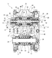
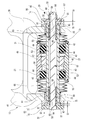
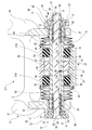
- FIG. 2 is a vertical sectional view of the disc brake shown in FIG. 3 is a horizontal cross-sectional view of the main part of the disc brake shown in FIG.
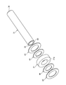
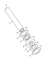
- FIG. 4 is an exploded perspective view of an inner peripheral washer and a rubber ring fitted into the guide pin shown in FIG.
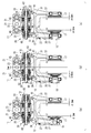
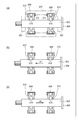
- FIG. 5 is a diagram for explaining the operation of the disc brake shown in FIG. 1.
- FIG. 5 (a) is a diagram for explaining the operation at the time of initializing
- FIG. 5 (b) is a diagram for explaining the operation at the time of brake braking
- c) is an operation explanatory diagram when the brake is slowly opened.
- FIG. 5 (a) is a diagram for explaining the operation at the time of initializing
- FIG. 5 (b) is a diagram for explaining the operation at the time of brake braking
- c) is an operation explanatory diagram when the brake is slowly opened.
- FIG. 6 is a horizontal sectional view of an essential part of a disc brake according to a second embodiment of the present invention.
- FIG. 7 is an exploded perspective view of an inner peripheral washer and a rubber ring fitted into the guide pin shown in FIG.
- FIG. 8 is a horizontal sectional view of an essential part of a disc brake according to a third embodiment of the present invention.
- FIG. 9 is an exploded perspective view of an inner peripheral washer and a rubber ring fitted into the guide pin shown in FIG.
- FIG. 10 is a horizontal sectional view of an essential part of a disc brake according to a fourth embodiment of the present invention.
- FIG. 11 is an exploded perspective view of the inner peripheral washer and the rubber ring fitted into the guide pin shown in FIG.
- FIG. 12A is a schematic diagram showing the posture of the retraction rubber ring with respect to the guide pin during non-braking in the conventional configuration
- FIG. 12B is a diagram of the retraction rubber ring during braking in FIG.
- FIG. 12 (c) is a schematic diagram showing the action of the retraction rubber ring during repositioning.
- the floating caliper type disc brake 11 according to the first embodiment of the present invention will be described by taking as an example a case of being used for a railcar disc brake.
- the disc brake 11 can be suitably used in various industrial drive device brake devices that generate a braking force on a rotating member such as an elevator.
- the floating caliper type disc brake 11 includes a wheel 35 (see (a) to (c) of FIG. 5) from a base 25 slidably supported on a support 23 coupled to a carriage frame (not shown).
- the floating caliper 13 has a piston-side pressing arm 39 and a counter-piston-side pressing arm 41 which are a pair of pressing arms extended to positions sandwiching the disk rotors 37, 37 attached to both side surfaces of the reference) from both sides in the axial direction.
- a pair of brake pads 17 and 17 provided on the piston-side pressing arm 39 and the anti-piston-side pressing arm 41 so as to face the outer surfaces of the disk rotors 37 and 37, respectively, and a piston-side pressing arm 39.
- the caliper return arranged at both ends of the drive piston 15 (see the partially broken portion in FIG. 5A) and the upper guide pin (guide pin) 31 It has a mechanism 20, 22 as main components.
- the upper guide pin 31 is formed as a hollow pipe.
- An upper guide pin 31 that is a guide pin with respect to an upper cylindrical support portion 27 and a lower cylindrical support portion 29 that are a pair of upper and lower cylindrical support portions of the support 23 are provided above and below the base portion 25 in the floating caliper 13.
- Lower guide pins 33 are spanned.
- the base 25 of the floating caliper 13 is slidably supported on the upper cylindrical support 27 and the lower cylindrical support 29 via the upper guide pin 31 and the lower guide pin 33. Both ends of the upper guide pin 31 are prevented from coming off from the base portion 25 by caliper return mechanisms 20 and 22.
- the lower guide pin 33 is fixed to the base portion 25 by a flange 34 and a nut 36.
- the base portion 25 of the floating caliper 13 is a pair of pressing arms up to a position sandwiching the disk rotor 37 attached to both sides of the wheel 35 (see FIGS. 5A to 5C) from both sides in the axial direction.
- the piston side pressing arm 39 and the anti-piston side pressing arm 41 are extended. Note that the piston-side pressing arm 39 and the anti-piston-side pressing arm 41 in the first embodiment are each composed of a bifurcated arm portion.
- the brake pads 17 are provided at the tip portions of the piston-side pressing arm 39 and the anti-piston-side pressing arm 41 so as to face the outer surface of the disc rotor 37 attached to both side surfaces of the wheel 35.
- a structure in which the lining surface of the brake pad 17 presses the disc rotor 37 to perform a brake operation will be described as an example.
- the disc brake 11 may be configured to brake by directly pressing both side surfaces of the wheel 35.
- the drive piston 15 is provided on a piston-side pressing arm 39 that is one of a pair of pressing arms in order to drive one of the brake pads 17 toward the side surface of the disc rotor 37.
- the caliper return mechanisms 20 and 22 are disposed at both ends of the upper guide pin 31 in the first embodiment.
- the caliper return mechanism 20 elastically biases the base portion 25 slidably supported with respect to the upper guide pin 31 to the drive piston side, and the caliper return mechanism 22 elastically applies the base portion 25 to the side opposite to the drive piston side. Rush.
- the caliper return mechanism according to the present invention is provided at least at the end (the left end in FIG. 3) opposite to the drive piston side at both ends of the upper guide pin 31 like the caliper return mechanism 22. Good.
- the caliper return mechanisms 20 and 22 are provided only on the upper guide pin 31 will be described.
- the caliper return mechanisms 20 and 22 are provided on both the upper guide pin 31 and the lower guide pin 33. It may be provided.
- the caliper return mechanism 20 includes a spring housing member 59 mounted on a spring housing portion 69 provided in a piston side end opening (end portion) 38 of a hollow upper guide pin 31, and an upper guide pin.
- a compression spring member 65 interposed between the bottom portion 58.
- the spring accommodating member 59 is formed in a bottomed cylindrical shape and has an open end flange 57 on the open end side.
- the caliper return mechanism 22 has a spring accommodating member 59 attached to a spring accommodating portion 69 provided in the opposite piston end opening (end) 32 of the hollow upper guide pin 31 and the upper guide pin 31.
- a sliding bearing 61 for slidably supporting the base 25, a spring receiving member 63 covering the opening of the upper guide pin 31 serving as the spring accommodating portion 69, a spring receiving member 63, and a bottom 58 of the spring accommodating member 59 A compression spring member 65 interposed therebetween.
- the spring accommodating member 59 is attached to a spring accommodating portion 69 that is recessed in the piston side end opening 38 and the anti-piston side end opening (end portion) 32 of the upper guide pin 31, respectively.
- the opening end flange 57 is locked to the opening edge of the spring accommodating portion 69, and further insertion into the spring accommodating portion 69 is restricted.
- the compression spring member 65 may be an elastic member such as rubber.
- the sliding bearing 61 is formed in a cylindrical shape, is fitted into the guide pin support portion 71 of the spring receiving members 63 and 66, and is disposed between the upper guide pin 31 and the spring receiving members 63 and 66.
- the slide bearing 61 reduces the sliding resistance of the base portion 25 with respect to the upper guide pin 31. Therefore, spring receiving members 63 and 66 are slidably fitted on the outer peripheral sides of both ends of the upper guide pin 31.
- the spring receiving member 66 includes a cylindrical guide pin support portion 71 and an annular spring support portion 68.
- the spring receiving member 63 has a cylindrical guide pin support portion 71 and an annular spring support portion 72.
- the guide pin support portion 71 is formed in a cylindrical shape, and is fixed to the base portion 25 so as to slidably support the upper guide pin 31 via the slide bearing 61. Further, between the guide pin support portion 71 and the base portion 25, there is provided a detent mechanism for restricting relative rotation of each other by engaging the notch portion 76 of the collar portion 75 with the locking rib 78 of the base portion 25. It has been.
- the spring support 68 and the spring support 72 are respectively in contact with the opening 56 at the bottom 58 of the spring housing member 59 so as to cover the outer opening end of the guide pin support 71 while being in contact with one end of the compression spring member 65. It is fixed to the base 25 together with the guide pin support portion 71 by a bolt shaft 62 penetrating through the hollow upper guide pin 31 in the central axis direction and a nut 70 screwed to the tip of the bolt shaft 62. Thereby, the spring receiving members 63 and 66 are fixed integrally with the base portion 25. The spring receiving members 63 and 66 fixed integrally with the base portion 25 are slidable on the upper guide pin 31 via the sliding bearing 61.
- the base 25 is slidably supported with respect to the upper guide pin 31 via the spring receiving members 63 and 66.
- the spring support portions 72 and 68 are removed while the guide pin support portions 71 of the spring receiving members 63 and 66 fixed to the base portion 25 of the floating caliper 13 are slidably supported on the outer periphery of the upper guide pin 31.
- the compression spring member 65 can be attached and detached.
- the return force and return amount of the floating caliper 13 can be adjusted very easily by replacing the spring support portions 72 and 68 and the compression spring member 65 with different specifications (predetermined interval S1, spring constant, etc.). Become.
- an O-ring 80 is mounted between the washer 84 tightened by the nut 70 and the spring support portion 68, and the O-ring is interposed between the spring support portion 68 and the flange portion 75 of the guide pin support portion 71.
- 81 is mounted.
- an O-ring 82 is mounted between the bolt head 64 of the bolt shaft 62 and the spring support portion 72, and an O-ring 81 is interposed between the spring support portion 72 and the flange portion 75 of the guide pin support portion 71. Is installed.
- the O-rings 80 and 82 seal the through holes of the spring support portions 68 and 72 through which the bolt shaft 62 passes, respectively, and the O-ring 81 is provided between the guide pin support portion 71 and the spring support portions 68 and 72.
- the mating portion is sealed in a watertight manner to prevent water and dust from entering the spring accommodating portion 69 and the spring accommodating member 59.
- the notch portion 74 of the spring support portion 72 engages with the locking projection 77 of the flange portion 75, thereby restricting relative rotation of each other.
- a stop mechanism is provided between the spring support portion 72 and the bolt shaft 62.
- a bolt head 64 having a two-sided width is fitted into the fitting recess 73 of the spring support portion 72 so as to restrict relative rotation of each other. Is provided. Therefore, when the nut 70 is screwed onto the tip of the bolt shaft 62, the bolt shaft 62 does not idle and the assembly workability is improved.
- the compression spring member 65 is housed inside the spring housing member 59, as shown in FIGS. One end of the compression spring member 65 accommodated in each spring accommodating member 59 abuts on the bottom 58 of the spring accommodating member 59 and the other end is the spring support portion 72 of the spring receiving member 63 (or the spring support of the spring receiving member 66). Part 68).
- Each compression spring member 65 includes a spring receiving member 66 (or a spring receiving member 63) in a state having a predetermined interval S1 with respect to the open end flange 57 of the spring accommodating member 59, and a bottom 58 of the spring accommodating member 59. It is inserted between.
- the caliper returning mechanisms 20 and 22 have a stopper portion 85 (see FIG. 3).
- the stopper portion 85 is formed in a step shape on the inner periphery of the guide pin support portion 71.
- the stopper portion 85 abuts against the opening end flange 57 of the spring housing member 59 to restrict the movement of the spring housing member 59 in the axial direction with respect to the base portion 25 via the guide pin support portion 71 at a predetermined interval S1. That is, the movement of the spring housing member 59 in the caliper return mechanisms 20 and 22 is restricted to the predetermined interval S1 by the stopper portion 85 of the guide pin support portion 71 in the spring receiving member 66 (or the spring receiving member 63).
- a pair of rubber rings 21 that elastically support the upper guide pin 31 in the radial direction are fitted inside the upper cylindrical support portion 27 of the support 23.
- inner peripheral side washers 44 fitted into the upper guide pins 31 are arranged on the both sides in the axial direction of the rubber ring 21.
- the inner peripheral side washer 44 is configured such that the outer peripheral side washer 43 fixed to the inner peripheral surface of the upper cylindrical support portion 27 comes into contact with the surface of the inner peripheral side washer 44 opposite to the surface that contacts the rubber ring 21. Movement along the axial direction of the upper guide pin 31 is restricted. That is, the outer peripheral washer 43 restricts movement in the direction along the upper guide pin 31 of the rubber ring 21 via the inner peripheral washer 44.
- a centering bearing 49 is fixed by a step 45 and a snap ring 47 at the center of the inner peripheral surface of the upper cylindrical support 27 surrounding the upper guide pin 31.
- the aligning bearing 49 supports the upper guide pin 31 in a swingable manner.
- the upper guide pin 31 and the upper cylindrical support portion 27 of the support 23 are not connected to each other because the wheel 35 elastically supported by the carriage frame is displaced (swing) relative to the carriage frame. Even if they are parallel, the sliding surfaces of the brake pad 17 and the disk rotor 37 can be brought into close contact with each other during braking.
- a rubber bush 52 and a sleeve 51 are interposed between the lower guide pin 33 and the lower cylindrical support portion 29 as shown in FIG.
- the lower guide pin 33 is supported slidably in the axial direction with respect to the lower cylindrical support portion 29 via the rubber bush 52 and the sleeve 51 instead of the aligning bearing 49.
- the pair of rubber rings 21 are disposed on both sides in the axial direction of the aligning bearing 49 on the inner peripheral surface of the upper cylindrical support portion 27.
- the pair of rubber rings 21 are slidably fitted to the upper cylindrical support portion 27 and elastically support the upper guide pin 31 in the radial direction.
- each rubber ring 21 has a stepped portion 53 formed on the inner peripheral surface of the upper cylindrical support portion 27 via an inner peripheral side washer 44 and an outer peripheral side washer 43.
- the pair of rubber rings 21 are fixed to the inner peripheral surface of the upper cylindrical support portion 27 in a state where movement in the axial direction is restricted.
- a rubber ring 21 having a shape and material having a high elastic range (deformation amount) is selected.
- the cross-sectional shape of the surface including the axis of the rubber ring 21 is a rectangular shape. As shown in FIG. 3, the rubber ring 21 is in sliding contact with the outer peripheral surface of the upper guide pin 31 on the inner peripheral surface side.
- the cross-sectional shape of the rubber ring according to the present invention is not limited to the rectangular cross section of the rubber ring 21 in the first embodiment, but a U-shaped cross section having an annular groove that can hold grease on the inner peripheral surface. Various shapes such as a cross section and an H-shaped section can be adopted.
- the sliding resistance value between the inner peripheral surface of the rubber ring and the outer peripheral surface of the upper guide pin 31 is set to an appropriate value of 5 to 50 kgf. Therefore, high-performance grease mixed with solidified lubricant such as molybdenum disulfide can be held.
- solidified lubricant such as molybdenum disulfide
- the inner periphery of the rubber ring 21 is in sliding contact with the outer peripheral surface of the upper guide pin 31, but the inner ring washer 44 is disposed on both sides in the axial direction of the rubber ring 21 and inserted into the upper guide pin 31.
- the inner peripheral portion is restricted from being bent and deformed along the axial direction of the upper guide pin 31. Therefore, the rubber ring 21 has an inner peripheral portion along the axial direction of the upper guide pin 31 due to the movement of the upper guide pin 31 during braking as in the conventional retraction rubber ring 513 (see FIG. 12B).
- the rubber ring 21 elastically supports the upper guide pin 31 only in the radial direction.
- the drive piston side is opposite (hereinafter referred to as the anti-drive piston side).
- the rubber ring 21 does not produce a force for returning the upper guide pin 31 to the above, but only the caliper returning force of the caliper returning mechanism 20 acts.
- the force relationship necessary for the caliper returning force is as follows. That is, F1: sliding resistance of the upper guide pin 31 and the support 23 (aligning bearing 49, rubber ring 21), F2: spring force of the compression spring member 65, F3: lower guide pin 33 and the support 23 (sleeve 51) Sliding resistance, F4: When the sliding resistance of the sliding bearing 61 at both ends of the upper guide pin 31 is set, F1>F2> (F3 + F4) It is set so as to have a power relationship of
- the floating caliper 13 is such that the base 25 on the side opposite to the piston side pressing arm 41 has a spring bearing on the side opposite to the driving piston (right side in FIG. 5B).
- the member 63 is moved in a direction to approach the disc rotor 37 (leftward in FIG. 5B), and the base 25 on the piston side pressing arm 39 side is left on the driving piston side (left side in FIG. 5B).
- Spring receiving member 66 is moved away from the disc rotor 37 (leftward in FIG. 5B).
- the caliper return force is accumulated in the caliper return mechanism 22 disposed on the counter drive piston side.
- the compression spring member 65 When the compression spring member 65 is compressed, the spring receiving member 63 moves on the outer periphery of the upper guide pin 31 with sliding resistance reduced in the direction along the axis by the slide bearing 61. Due to the movement of the spring receiving member 63, the spring support portion 72 on the counter drive piston side is locked to the counter piston side end opening 32 (see FIG. 3) of the upper guide pin 31 as shown in FIG. It abuts on the open end flange 57.
- the piston side pressing arm 39 moves the spring receiving member 66 on the driving piston side in a direction away from the disk rotor 37. Then, the spring accommodating member 59 on the drive piston side is moved in a direction in which the opening end flange 57 is pressed by the stopper portion 85 of the spring receiving member 66 and is pulled out from the spring accommodating portion 69 of the upper guide pin 31. Thereby, a gap (interference avoidance gap) S2 is formed between the opening end flange 57 and the piston side end opening 38 (see FIG. 3) of the upper guide pin 31.
- the opening end flange 57 remains in contact with the stopper portion 85 due to the urging force of the compression spring member 65 and is separated from the spring support portion 68. Therefore, the compression spring member 65 on the drive piston side is arranged. Does not affect the compression deformation of the compression spring member 65 on the counter-drive piston side. The above is the state at the time of brake braking.
- the piston side pressing arm 39 moves the spring receiving member 66 on the driving piston side in a direction to approach the disk rotor 37.
- the interference avoidance gap S2 is formed between the opening end flange 57 and the piston side end opening 38 of the upper guide pin 31. For this reason, the elastic force of the compression spring member 65 on the drive piston side does not act as a reaction force (load) against the caliper return force.
- the clearance d between each brake pad 17 and the disc rotor 37 is set to 3 mm before braking (at the time of initializing).
- the compression spring member 65 on the counter drive piston side is compressed and deformed. The restoring force due to the deformation of the compression spring member 65 creates a force (retraction effect) for returning the floating caliper 13.
- the operation of the disc brake 11 having the above-described structure when the wheel is swung will be described.
- the wheel 35 swings with respect to the floating caliper 13 fixed to the carriage frame during braking during curve traveling.
- the clearance of both brake pads 17 is maintained at the same value even after the wheel is swung as long as the amount of wheel swing is twice the pad clearance.
- the floating caliper type disc brake 11 of the first embodiment can secure both pad clearances of 3 mm up to a wheel swing amount of ⁇ 6 mm.
- the pressing force of the brake pad 17 against the disc rotor 37 is generated by the compression deformation of the compression spring member 65 on the drive piston side. That is, when the wheel 35 swings 6 mm in the direction of the drive piston from the initial time when the wheel 35 is initialized, the displacement amount between the support 23 and the base portion 25 becomes 3 mm, and the displacement amount between the wheel 35 and the base portion 25 becomes 3 mm. .
- a return force of 3 mm is generated in the caliper return mechanism 20 on the drive piston side. If the disc brake 11 is released from the swinging, it is possible to secure a pad clearance of 3 mm.
- the disc brake 11 at the initial time has a displacement amount of 7 mm between the support 23 and the base portion 25 and a deviation amount between the wheel 35 and the base portion 25 becomes 3 mm. . Therefore, when the wheel return amount is 6 mm, the shift amount between the support 23 and the base portion 25 is 4 mm, and the shift amount between the wheel 35 and the base portion 25 is 0 mm.
- the pad clearance between the disc rotor 37 and the brake pad 17 is 3 mm.
- the wheel return amount is 9 mm
- the amount of deviation between the support 23 and the base portion 25 is 4 mm
- the amount of deviation between the wheel 35 and the base portion 25 is 0 mm.
- the remaining amount of movement of the wheel 35 is 1 mm, and the disc rotor 37 contacts the brake pad 17.
- the compression spring member 65 on the drive piston side bends, and a pressing force of the brake pad 17 against the disc rotor 37 is generated.
- the base portion 25 of the floating caliper 13 is slidable with respect to the upper cylindrical support portion 27 of the support 23.
- Caliper return mechanisms 20 and 22 are provided at both ends of the upper guide pin 31 to be supported.
- the caliper return mechanism 22 on the counter drive piston side generates a caliper return force between the upper guide pin 31 and the floating caliper 13. Therefore, the caliper return mechanism 22 on the counter-drive piston side separates the pair of brake pads 17 from the disc rotor 37 with the same clearance as before braking by the caliper return force when the brake is released.
- the upper guide pin 31 provided with the caliper return mechanisms 20 and 22 only needs to be replaced with the upper guide pin in the existing floating caliper, and there is no additional modification to the existing floating caliper. Improvements can be made to realize pad drag countermeasures against the brake.
- the rubber rings 21 that are fitted inwardly of the upper cylindrical support portion 27 and elastically support the upper guide pins 31 in the radial direction are arranged on both sides in the axial direction of the rubber rings 21 and are inserted into the upper guide pins 31.
- the inner peripheral washer 44 is configured to restrict the inner peripheral portion from being bent and deformed along the axial direction of the upper guide pin 31. Therefore, the rubber ring 21 has an inner peripheral portion in the axial direction of the upper guide pin 31 due to the movement of the upper guide pin 31 during braking, like a conventional retraction rubber ring 513 (see FIG. 12B). Therefore, the upper guide pin 31 is not moved in the axial direction by the elastic restoring force. Accordingly, the caliper return mechanisms 20 and 22 can stably generate the caliper return force without being affected by variations in the frictional resistance of the rubber ring 21 that elastically supports the upper guide pin 31 in the radial direction.
- the inner peripheral washer 44 fitted into the upper guide pin 31 is fixed by the outer peripheral washer 43 fixed to the inner peripheral surface of the upper cylindrical support portion 27.
- the upper guide pin 31 is positioned with respect to the axial direction.
- the inner washer 44 inserted into the upper guide pin 31 has a clearance with respect to the inner peripheral surface of the upper cylindrical support portion 27 and is fixed to the inner peripheral surface of the upper cylindrical support portion 27.
- the side washer 43 has a clearance with respect to the outer peripheral surface of the upper guide pin 31. Therefore, the inner peripheral washer 44 positioned in the axial direction by the outer peripheral washer 43 can follow the movement of the upper guide pin 31 in the radial direction by slipping at the surface contact portion with the outer peripheral washer 43. it can.
- the caliper returning mechanisms 20 and 22 are disposed at both ends of the upper guide pin 31, for example, the counter-driving required when the wheel 35 swings is performed. It is possible to create a force for returning the base portion 25 of the floating caliper 13 to the piston side. Since the inner peripheral side washers 44 of the first embodiment are disposed on both axial sides of the rubber ring 21, not only the deformation of the rubber ring 21 due to the movement of the upper guide pin 31 during braking, but also the above-described wheels. The bending deformation of the rubber ring 21 due to the movement of the upper guide pin 31 in the opposite direction when the floating caliper 13 is moved by the swinging of the 35 can also be restricted.
- the brake pads 17 are pressed against the disc rotors 37 attached to both side surfaces of the railcar wheel 35 for braking. In doing so, the pad clearance between the brake pad 17 and the disc rotor 37 can be maintained constant. As a result, it is possible to prevent uneven wear and drag of the brake pad 17 and to suppress an increase in the starting torque of the vehicle.
- the floating caliper type disc brake 111 according to the second embodiment the same members as those in the floating caliper type disc brake 11 according to the first embodiment are denoted by the same reference numerals, and redundant description is omitted.
- the floating caliper type disc brake 111 according to the second embodiment is provided on the inner peripheral surface 21 a of the rubber ring 21 ⁇ / b> A fitted inside the upper cylindrical support portion 27.
- a fitting member 50 interposed between the upper guide pin 31 and the upper guide pin 31 is disposed.
- the fitting member 50 is a cylindrical member made of metal or resin, and has a slit 54. Then, the fitting member 50 is fitted and inserted along the inner peripheral surface 21a of the rubber ring 21A in a state of being elastically deformed in the reduced diameter direction. Therefore, the fitting member 50 fitted and inserted into the inner peripheral surface 21a of the rubber ring 21A can be fitted with the upper guide pin 31 with an allowance.
- the fitting member 50 is interposed between the inner peripheral surface 21a of the rubber ring 21A and the upper guide pin 31, so that the rubber The sliding resistance of the upper guide pin 31 with respect to the ring 21 ⁇ / b> A is stabilized, the width of the axial force fluctuation is reduced when the upper guide pin 31 slides, and the caliper returning force of the caliper returning mechanisms 20 and 22 is stabilized. Further, since the fitting member 50 fitted on the inner peripheral surface 21a of the rubber ring 21A can be fitted with the upper guide pin 31 with a tightening margin, the upper guide pin 31 has a sliding resistance against the rubber ring 21A. Is more stable.
- the floating caliper type disc brake 211 according to the third embodiment is provided on the inner peripheral surface 21 a of the rubber ring 21 ⁇ / b> A fitted inside the upper cylindrical support portion 27.
- a fitting member 50B interposed between the upper guide pin 31 and the upper guide pin 31 is disposed.
- the inner peripheral end of the inner peripheral washer 46 has a cylindrical extending portion 48 extending along the inner peripheral surface 21a of the rubber ring 21A.
- the fitting member 50 ⁇ / b> B is a cylindrical member made of metal or resin, and has a slit 54.
- the fitting member 50B is inserted and inserted along the inner peripheral surface 21a of the rubber ring 21A in a state of being elastically deformed in the diameter reducing direction. Therefore, the fitting member 50B fitted on the inner peripheral surface 21a of the rubber ring 21A can be fitted with the upper guide pin 31 with a tightening margin.
- the inner peripheral washer 46 has a cylindrical extension 48 formed by bending the inner peripheral end of the annular inner peripheral washer into an L-shaped cross section by, for example, burring.
- the pair of inner peripheral side washers 46 are fitted to the inner peripheral surface 21a of the rubber ring 21A so that the extending portions 48 sandwich the fitting member 50B fitted and inserted into the rubber ring 21A from both opening end sides. That is, the inner washer 46 and the fitting member 50B are fitted to the inner circumferential surface 21a of the rubber ring 21A by the extending portion 48, and the positions thereof are determined in advance. Therefore, it is not necessary to perform positioning when the upper guide pin 31 is assembled to the upper cylindrical support portion 27 of the support 23, and the assemblability is good.
- the opening edge of the inner peripheral side washer 46 has an R portion in which the entrance is bent rather than the edge by the cylindrical extending portion 48, so that the inner peripheral side washer 46 is inserted into the upper guide pin 31.
- the upper guide pin 31 can be smoothly inserted without being caught by the inner peripheral washer 46.
- the floating caliper type disc brake 311 according to the fourth embodiment includes a rubber ring 21B fitted inside the upper cylindrical support portion 27, and a shaft of the rubber ring 21B. And inner washers 46 disposed on both sides in the direction.
- the rubber ring 21B has an annular protrusion 21b that protrudes from the axially central portion of the inner peripheral surface 21a.
- the inner peripheral washer 46 has a cylindrical extending portion 48 whose inner peripheral end extends along the inner peripheral surface 21a of the rubber ring 21B. Therefore, the pair of inner peripheral washers 46 are fitted to the inner peripheral surface 21a of the rubber ring 21B so that the extended portions 48 sandwich the annular protrusion 21b of the rubber ring 21B from both opening end sides. That is, the inner peripheral washer 46 is fitted to the inner peripheral surface 21a of the rubber ring 21B by the extending portion 48, and the position is determined in advance.
- the opening edge of the inner peripheral side washer 46 has an R portion in which the entrance is bent rather than the edge by the cylindrical extending portion 48, so that the inner peripheral side washer 46 is inserted into the upper guide pin 31.
- the upper guide pin 31 can be smoothly inserted without being caught by the inner peripheral washer 46.
- the caliper return force can be easily set, and the desired caliper can be set.
- the return operation can be exhibited stably, and the brake pad 17 can be reliably prevented from being dragged.
- a base (slidably supported via a guide pin (upper guide pin 31) with respect to the cylindrical support (upper cylindrical support 27 and lower cylindrical support 29) of the support (23).
- the base portion which is disposed at least on the opposite side of the drive piston side at both ends of the guide pin and is slidably supported with respect to the guide pin, is elastically biased to the side opposite to the drive piston side.
- the rubber ring is arranged at least on the drive piston side on both sides in the axial direction of the rubber ring, and is inserted into the guide pin to restrict the inner peripheral portion of the rubber ring from being bent and deformed along the axial direction of the guide pin.
- Disc brake
- the inner peripheral end of the inner peripheral washer is The disc brake according to the above [1] or [2], wherein the disc brake has a cylindrical extension extending along the inner peripheral surface of the rubber ring.
- the fitting member is The disc brake according to the above [4], which is formed of a cylindrical member having a slit and is fitted and inserted along the inner peripheral surface of the rubber ring in a state of being elastically deformed in the diameter reducing direction.
- the inner peripheral washer is The disc brake according to any one of [1] to [5], which is disposed on both axial sides of the rubber ring.
- a railway vehicle disc brake comprising the disc brake according to any one of [1] to [6].
- this invention is not limited to embodiment mentioned above, A deformation
- the material, shape, dimensions, number, arrangement location, and the like of each component in the above-described embodiment are arbitrary and are not limited as long as the present invention can be achieved.
- This application is based on a Japanese patent application filed on March 30, 2016 (Japanese Patent Application No. 2016-068673), the contents of which are incorporated herein by reference.
- the caliper return force can be easily set, and the desired caliper return operation can be stably exhibited to reliably prevent pad dragging. Therefore, it is possible to provide a good disc brake and a railcar disc brake that can prevent an increase in starting torque and prevent lining wear.
Landscapes
- Engineering & Computer Science (AREA)
- General Engineering & Computer Science (AREA)
- Mechanical Engineering (AREA)
- Braking Arrangements (AREA)
Abstract
ディスクブレーキ(11)は、サポート(23)に支持された上段ガイドピン(31)に摺動自在に支承された基部(25)と、ピストン側押圧腕(39)及び反ピストン側押圧腕(41)とを有するフローティングキャリパ(13)と、一対のブレーキパッド(17)と、ピストン側押圧腕(39)に設けられた駆動ピストン(15)と、上段ガイドピン(31)の端部に配置されて基部(25)を駆動ピストン側と反対側へ弾性付勢するためのキャリパ戻し機構(22)と、上段ガイドピン(31)を径方向に弾性支持するゴムリング(21)の軸方向両側に配置されて該ゴムリング(21)の内周部が上段ガイドピン(31)の軸方向に沿って撓み変形するのを規制する内周側ワッシャ(44)と、を備える。
Description
本発明は、ディスクブレーキ及び鉄道車両用ディスクブレーキに関する。
ブレーキパッドの引摺り現象が防止されたフローティングキャリパ型のディスクブレーキが、従来から知られている(特許文献1参照)。
このフローティングキャリパ型のディスクブレーキは、一方のパッド(ブレーキパッド)が、両端部を二股に開いたキャリパ(フローティングキャリパ)の一端の腕に固定され、他方のパッドがこれと反対側の腕に設けたピストン(駆動ピストン)によりロータに向けて押し出されるように構成されている。キャリパの他端の腕には、2本のガイドピンが固定され、これらのガイドピンは、台車枠等に結合されたサポートの筒状部に軸方向へ摺動自在に支承されている。
このフローティングキャリパ型のディスクブレーキは、一方のパッド(ブレーキパッド)が、両端部を二股に開いたキャリパ(フローティングキャリパ)の一端の腕に固定され、他方のパッドがこれと反対側の腕に設けたピストン(駆動ピストン)によりロータに向けて押し出されるように構成されている。キャリパの他端の腕には、2本のガイドピンが固定され、これらのガイドピンは、台車枠等に結合されたサポートの筒状部に軸方向へ摺動自在に支承されている。
すなわち、図12の(a)に示すように、キャリパの二股になった一対の腕501の間には、上下一対のガイドピン503(上側のみを図示する)が掛渡され、それぞれフランジ505とナット(図示略)とにより腕501に固定されている。上側のガイドピン503を囲むサポート(図示略)の筒状部507の内面には、一対の保持リング509が段部511とスナップリング(図示略)とにより挟持されて取り付けられている。この保持リング509の内側には、断面がH形状のリトラクションゴムリング(フリクションゴムリング)513が嵌着されている。
上記の構成において、非制動時は、断面H形のリトラクションゴムリング513の内周の突条515における先端部が、図12の(a)のように、ガイドピン503の外周面に真直に当接している。
制動すると、パッドがロータに押付けられた反力でガイドピン503がキャリパと共に図12の(b)の矢印(A)の方向に移動する。これと共にガイドピン503の外周面と突条515の先端部との摩擦のため、リトラクションゴムリング513の突条515が矢印(A)の方向に曲がる(撓む)。
制動すると、パッドがロータに押付けられた反力でガイドピン503がキャリパと共に図12の(b)の矢印(A)の方向に移動する。これと共にガイドピン503の外周面と突条515の先端部との摩擦のため、リトラクションゴムリング513の突条515が矢印(A)の方向に曲がる(撓む)。
制動を解除すると、リトラクションゴムリング513はその弾性力のため元の姿勢に戻ろうとし、内周の突条515の先端部とガイドピン503の外周面との摩擦によりガイドピン503が、図12の(c)の矢印(B)の方向へ動かされる。これによりガイドピン503に結合されたキャリパが矢印(B)の方向へ僅かに移動し、キャリパに固定されたパッドをロータから僅かながら離す。これにより車両の始動を軽くすることができる。車両が走行を始めると、振動等のためパッドとロータとの間隙は十分大きくなる。
このようなフローティングキャリパ型のディスクブレーキによれば、リトラクションゴムリング513によって、制動解除時に直ちにキャリパに固定されたパッドをロータから引離して、引摺りを防止し、始動トルクの増大を防ぎ、ライニングの摩耗を防止することができる。
しかしながら、上述した従来のフローティングキャリパ型のディスクブレーキは、リトラクションゴムリング513のみでキャリパのリトラクション効果(戻し力)と戻し量を管理しているため、リトラクションゴムリング513の製造バラつきや寸法公差などによって所望するキャリパ戻し動作を安定的に発揮させることが難しいという問題があった。すなわち、戻し力をリトラクションゴムリング513のみによって得るのでは限界がある。また、異なる仕様のキャリパに対しては、戻し量の微調整が必要となるため、既存のキャリパ(鋳物)に対して追加工を行ったりせずに戻し量の微調整が可能となる構造が望まれている。
本発明は上記状況に鑑みてなされたもので、その目的は、キャリパ戻し力の設定が容易に行なわれ、しかも、所望するキャリパ戻し動作が安定的に発揮されて、パッドの引き摺りを確実に防止できるディスクブレーキ及び鉄道車両用ディスクブレーキを提供することにある。
本発明に係る上記目的は、下記構成により達成される。
(1) サポートの筒状支持部に対しガイドピンを介して摺動自在に支承された基部と、該基部からディスクロータを軸方向両側から挟む位置にまで延出された一対の押圧腕とを有するフローティングキャリパと、前記ディスクロータの側面に対向するように前記一対の押圧腕の先端部にそれぞれ設けられた一対のブレーキパッドと、前記ブレーキパッドの一方を前記ディスクロータの側面に向けて駆動するために前記一対の押圧腕の一方に設けられた駆動ピストンと、前記ガイドピンの両端部における少なくとも前記駆動ピストン側と反対側の端部に配置され、前記ガイドピンに対して摺動自在に支持された前記基部を前記駆動ピストン側と反対側へ弾性付勢するためのキャリパ戻し機構と、前記筒状支持部の内方に嵌装されて前記ガイドピンを径方向に弾性支持するゴムリングと、前記ゴムリングの軸方向両側における少なくとも前記駆動ピストン側に配置されて前記ガイドピンに嵌挿されることにより、前記ゴムリングの内周部が前記ガイドピンの軸方向に沿って撓み変形するのを規制する内周側ワッシャと、を備えるディスクブレーキ。
(1) サポートの筒状支持部に対しガイドピンを介して摺動自在に支承された基部と、該基部からディスクロータを軸方向両側から挟む位置にまで延出された一対の押圧腕とを有するフローティングキャリパと、前記ディスクロータの側面に対向するように前記一対の押圧腕の先端部にそれぞれ設けられた一対のブレーキパッドと、前記ブレーキパッドの一方を前記ディスクロータの側面に向けて駆動するために前記一対の押圧腕の一方に設けられた駆動ピストンと、前記ガイドピンの両端部における少なくとも前記駆動ピストン側と反対側の端部に配置され、前記ガイドピンに対して摺動自在に支持された前記基部を前記駆動ピストン側と反対側へ弾性付勢するためのキャリパ戻し機構と、前記筒状支持部の内方に嵌装されて前記ガイドピンを径方向に弾性支持するゴムリングと、前記ゴムリングの軸方向両側における少なくとも前記駆動ピストン側に配置されて前記ガイドピンに嵌挿されることにより、前記ゴムリングの内周部が前記ガイドピンの軸方向に沿って撓み変形するのを規制する内周側ワッシャと、を備えるディスクブレーキ。
上記(1)の構成のディスクブレーキによれば、サポートの筒状支持部に対してフローティングキャリパの基部を摺動自在に支承するガイドピンにおける駆動ピストン側と反対側の端部には、キャリパ戻し機構が設けられる。キャリパ戻し機構は、ガイドピンとフローティングキャリパとの間に、キャリパ戻し力を発生させる。そこで、キャリパ戻し機構は、制動解除時にこのキャリパ戻し力によって一対のパッドを制動前と同じクリアランスでディスクロータから離間させる。キャリパ戻し機構が設けられたガイドピンは、現行のフローティングキャリパおけるガイドピンと交換されるだけでよく、既存のフローティングキャリパに対して一切の追加工なしに、ディスクブレーキに対するパッド引き摺り対策を実現するための改良が可能となる。
更に、筒状支持部の内方に嵌装されてガイドピンを径方向に弾性支持するゴムリングは、ゴムリングの軸方向両側における少なくとも駆動ピストン側に配置されてガイドピンに嵌挿された内周側ワッシャによって、内周部がガイドピンの軸方向に沿って撓み変形するのが規制される。そこで、ゴムリングは、従来のトラクションゴムリングのように、制動時のガイドピンの移動により内周部がガイドピンの軸方向に沿って撓み変形することがなく、その弾性復元力によってガイドピンを軸方向に移動させることがない。
従って、キャリパ戻し機構は、ガイドピンを径方向に弾性支持するゴムリングの摩擦抵抗のバラツキによる影響を受けることなく、キャリパ戻し力を安定的に発生することができる。
更に、筒状支持部の内方に嵌装されてガイドピンを径方向に弾性支持するゴムリングは、ゴムリングの軸方向両側における少なくとも駆動ピストン側に配置されてガイドピンに嵌挿された内周側ワッシャによって、内周部がガイドピンの軸方向に沿って撓み変形するのが規制される。そこで、ゴムリングは、従来のトラクションゴムリングのように、制動時のガイドピンの移動により内周部がガイドピンの軸方向に沿って撓み変形することがなく、その弾性復元力によってガイドピンを軸方向に移動させることがない。
従って、キャリパ戻し機構は、ガイドピンを径方向に弾性支持するゴムリングの摩擦抵抗のバラツキによる影響を受けることなく、キャリパ戻し力を安定的に発生することができる。
(2) 前記筒状支持部の内周面に固定された外周側ワッシャが、前記内周側ワッシャにおける前記ゴムリングに接触する面と反対側の面に当接することにより、前記ガイドピンの軸方向に沿う前記内周側ワッシャの移動が規制される上記(1)に記載のディスクブレーキ。
上記(2)の構成のディスクブレーキによれば、ガイドピンに嵌挿された内周側ワッシャは、筒状支持部の内周面に固定された外周側ワッシャによりガイドピンの軸方向に対して位置決めされる。そして、ガイドピンに嵌挿された内周側ワッシャは筒状支持部の内周面に対してクリアランスを有し、筒状支持部の内周面に固定された外周側ワッシャはガイドピンの外周面に対してクリアランスを有する。そこで、外周側ワッシャにより軸方向に位置決めされた内周側ワッシャは、外周側ワッシャとの面接触部で滑りが生じることにより、ガイドピンの径方向の動きに追従することができる。
(3) 前記内周側ワッシャの内周端が、前記ゴムリングの内周面に沿って延びる円筒状の延出部を有する上記(1)又は(2)に記載のディスクブレーキ。
上記(3)の構成のディスクブレーキによれば、内周側ワッシャは、延出部によってゴムリングの内周面に嵌合されて予め位置が決まっている。そこで、ガイドピンをサポートの筒状支持部に組付ける際に位置決めを行う必要がなく、組付け性がよい。
また、円筒状の延出部は、例えばバーリング加工等によって円環状の内周側ワッシャの内周端を断面L字状に曲げ加工することで形成される。そこで、内周側ワッシャをガイドピンに挿入する時、内周側ワッシャの入り口がエッジではなく曲げ加工されたR部を有しているため、ガイドピンが内周側ワッシャに引っかかることなくスムーズに挿入できる。
また、円筒状の延出部は、例えばバーリング加工等によって円環状の内周側ワッシャの内周端を断面L字状に曲げ加工することで形成される。そこで、内周側ワッシャをガイドピンに挿入する時、内周側ワッシャの入り口がエッジではなく曲げ加工されたR部を有しているため、ガイドピンが内周側ワッシャに引っかかることなくスムーズに挿入できる。
(4) 前記ゴムリングの内周面には、前記ガイドピンとの間に介装される嵌合部材が配置されている上記(1)~(3)の何れか1つに記載のディスクブレーキ。
上記(4)の構成のディスクブレーキによれば、ゴムリングの内周面とガイドピンとの間に嵌合部材が介装されることで、ゴムリングに対するガイドピンの摺動抵抗が安定し、ガイドピンが摺動する際に軸力変動の幅が小さくなり、キャリパ戻し機構のキャリパ戻し力が安定する。
また、ゴムリングがガイドピンと接触しないため、ゴムリングとガイドピンの固着や、固着によるゴムリングの千切れが起こらなくなる。
また、ゴムリングがガイドピンと接触しないため、ゴムリングとガイドピンの固着や、固着によるゴムリングの千切れが起こらなくなる。
(5) 前記嵌合部材が、すり割りを有する円筒状部材から成り、縮径方向に弾性変形された状態で前記ゴムリングの内周面に沿って嵌挿されている上記(4)に記載のディスクブレーキ。
上記(5)の構成のディスクブレーキによれば、ゴムリングの内周面に嵌挿された嵌合部材は、ガイドピンと締め代をもって嵌合することができる。そこで、ガイドピンは、ゴムリングに対する摺動抵抗がより安定する。
(6) 前記内周側ワッシャが、前記ゴムリングの軸方向両側に配置されている上記(1)~(5)の何れか1つに記載のディスクブレーキ。
上記(6)の構成のディスクブレーキによれば、内周側ワッシャがゴムリングの軸方向両側に配置されることで、制動時のガイドピンの移動によるゴムリングの撓み変形だけでなく、例えばディスクロータの揺動によりフローティングキャリパが移動された際のガイドピンの反対方向の移動によるゴムリングの撓み変形も規制することができる。
(7) 上記(1)~(6)の何れか1つに記載のディスクブレーキを備えた鉄道車両用ディスクブレーキ。
上記(7)の構成の鉄道車両用ディスクブレーキによれば、上記のディスクブレーキの構成を備えることで、鉄道車両用の車輪の両側面に取り付けたディスクロータにブレーキパッドを押圧して制動する際に、ブレーキパッドとディスクロータのパッドクリアランスを一定に維持できる。これにより、ブレーキパッドの偏摩耗及び引きずりを防止するとともに、車両の始動トルクの増大を抑制可能とすることができる。
本発明に係るディスクブレーキ及び鉄道車両用ディスクブレーキによれば、キャリパ戻し力の設定が容易に行なわれ、しかも、所望するキャリパ戻し動作が安定的に発揮されて、パッドの引き摺りを確実に防止できる。
以上、本発明について簡潔に説明した。更に、以下に説明される発明を実施するための形態(以下、「実施形態」という。)を添付の図面を参照して通読することにより、本発明の詳細は更に明確化されるであろう。
以下、本発明に係る実施形態を図面を参照して説明する。
図1~図4に示すように、本発明の第1実施形態に係るフローティングキャリパ型のディスクブレーキ11は、鉄道車両用ディスクブレーキに用いられる場合を例に説明する。この他、ディスクブレーキ11は、例えばエレベータ等、回転部材に対して制動力を発生させる種々の産業用駆動装置のブレーキ装置にも好適に用いることができるものである。
図1~図4に示すように、本発明の第1実施形態に係るフローティングキャリパ型のディスクブレーキ11は、鉄道車両用ディスクブレーキに用いられる場合を例に説明する。この他、ディスクブレーキ11は、例えばエレベータ等、回転部材に対して制動力を発生させる種々の産業用駆動装置のブレーキ装置にも好適に用いることができるものである。
本第1実施形態に係るフローティングキャリパ型のディスクブレーキ11は、図示しない台車枠に結合されたサポート23に摺動自在に支承された基部25から車輪35(図5の(a)~(c)参照)の両側面に取り付けられたディスクロータ37,37を軸方向両側から挟む位置にまで延出された一対の押圧腕であるピストン側押圧腕39及び反ピストン側押圧腕41を有するフローティングキャリパ13と、ディスクロータ37,37の外側面に対向するようにピストン側押圧腕39及び反ピストン側押圧腕41にそれぞれ設けられた一対のブレーキパッド17,17と、ピストン側押圧腕39に設けられた駆動ピストン15(図5の(a)の部分破断部参照)と、上段ガイドピン(ガイドピン)31の両端部に配置されたキャリパ戻し機構20,22と、を主要な構成として有している。上段ガイドピン31は、中空のパイプとして形成される。
フローティングキャリパ13における基部25の上部及び下部には、サポート23の上下一対の筒状支持部である上段筒状支持部27及び下段筒状支持部29に対し、ガイドピンである上段ガイドピン31及び下段ガイドピン33がそれぞれ掛け渡されている。フローティングキャリパ13の基部25は、上段ガイドピン31及び下段ガイドピン33を介して上段筒状支持部27及び下段筒状支持部29に摺動自在に支承される。上段ガイドピン31は、両端がキャリパ戻し機構20,22により基部25から抜け止めされている。下段ガイドピン33は、フランジ34とナット36とにより基部25に固定されている。フローティングキャリパ13の基部25には、車輪35(図5の(a)~(c)参照)の両側面に取り付けられたディスクロータ37を軸方向両側から挟む位置にまで、一対の押圧腕であるピストン側押圧腕39及び反ピストン側押圧腕41が延設される。なお、本第1実施形態におけるピストン側押圧腕39及び反ピストン側押圧腕41は、それぞれ平行な二股の腕部により構成されている。
ブレーキパッド17は、車輪35の両側面に取り付けられたディスクロータ37の外側面に対向するようにピストン側押圧腕39及び反ピストン側押圧腕41の先端部にそれぞれ設けられる。なお、本第1実施形態では、ブレーキパッド17のライニング面が、ディスクロータ37を押圧してブレーキ動作を行う構造を例に説明する。勿論、ディスクブレーキ11は、車輪35の両側面を直接挟圧して制動する構成であってもよい。
駆動ピストン15は、本第1実施形態において、ブレーキパッド17の一方をディスクロータ37の側面に向けて駆動するために一対の押圧腕の一方であるピストン側押圧腕39に設けられている。
キャリパ戻し機構20,22は、本第1実施形態において、上段ガイドピン31の両端部に配置されている。キャリパ戻し機構20は、上段ガイドピン31に対して摺動自在に支持された基部25を駆動ピストン側へ弾性付勢し、キャリパ戻し機構22は、基部25を駆動ピストン側と反対側へ弾性付勢する。なお、本発明に係るキャリパ戻し機構は、キャリパ戻し機構22のように上段ガイドピン31の両端部における少なくとも駆動ピストン側と反対側の端部(図3中、左端部)に設けられていればよい。なお、本第1実施形態では、キャリパ戻し機構20,22が上段ガイドピン31にのみ設けられる例を説明するが、キャリパ戻し機構20,22は、上段ガイドピン31及び下段ガイドピン33の双方に設けられてもよい。
本第1実施形態に係るキャリパ戻し機構20は、中空の上段ガイドピン31のピストン側端開口部(端部)38に設けられたばね収容部69に装着されるばね収容部材59と、上段ガイドピン31に対して基部25を摺動自在に支持するための滑り軸受61と、ばね収容部69となる上段ガイドピン31の開口を覆うばね受け部材66と、ばね受け部材66とばね収容部材59の底部58との間に介装される圧縮ばね部材65と、を有する。
ばね収容部材59は、有底筒状に形成され、開口端側に開口端フランジ57を有する。
ばね収容部材59は、有底筒状に形成され、開口端側に開口端フランジ57を有する。
一方、キャリパ戻し機構22は、中空の上段ガイドピン31の反ピストン側端開口部(端部)32に設けられたばね収容部69に装着されるばね収容部材59と、上段ガイドピン31に対して基部25を摺動自在に支持するための滑り軸受61と、ばね収容部69となる上段ガイドピン31の開口を覆うばね受け部材63と、ばね受け部材63とばね収容部材59の底部58との間に介装される圧縮ばね部材65と、を有する。
ばね収容部材59は、上段ガイドピン31のピストン側端開口部38及び反ピストン側端開口部(端部)32に凹設されたばね収容部69にそれぞれ装着される。ばね収容部69に装着されたばね収容部材59は、開口端フランジ57がばね収容部69の開口縁に係止され、それ以上のばね収容部69への挿入が規制される。なお、本第1実施形態では、圧縮ばね部材65として圧縮コイルばねを用いる例を説明するが、この他、圧縮ばね部材65は、ゴム等の弾性部材であってもよい。
滑り軸受61は、円筒状に形成され、ばね受け部材63,66のガイドピン支持部71に内嵌されて、上段ガイドピン31とばね受け部材63,66との間に配設される。滑り軸受61は、上段ガイドピン31に対する基部25の摺動抵抗を軽減させる。そこで、上段ガイドピン31の両端の外周側には、ばね受け部材63,66が摺動自在に外挿される。
ばね受け部材66は、筒状のガイドピン支持部71と、円環状のばね支持部68とを有する。また、ばね受け部材63は、筒状のガイドピン支持部71と、円環状のばね支持部72とを有する。
ガイドピン支持部71は、円筒状に形成され、滑り軸受61を介して上段ガイドピン31を摺動自在に支持するため基部25に固定される。更に、ガイドピン支持部71と基部25との間には、鍔部75の切欠き部76が基部25の係止リブ78に係合することで互いの相対回転を規制する回り止め機構が設けられている。
ガイドピン支持部71は、円筒状に形成され、滑り軸受61を介して上段ガイドピン31を摺動自在に支持するため基部25に固定される。更に、ガイドピン支持部71と基部25との間には、鍔部75の切欠き部76が基部25の係止リブ78に係合することで互いの相対回転を規制する回り止め機構が設けられている。
ばね支持部68及びばね支持部72は、それぞれ圧縮ばね部材65の一端に当接された状態でガイドピン支持部71の外側開口端を覆うように、ばね収容部材59の底部58における開口56と中空の上段ガイドピン31とを中心軸方向に貫通したボルト軸62と、ボルト軸62の先端に螺着されたナット70とによって、ガイドピン支持部71と伴に基部25に固定される。これにより、ばね受け部材63,66は、基部25と一体に固定される。基部25と一体に固定されたばね受け部材63,66は、滑り軸受61を介して上段ガイドピン31に摺動自在となる。つまり、基部25は、ばね受け部材63,66を介して上段ガイドピン31に対して摺動自在に支持される。
なお、フローティングキャリパ13の基部25に固定されたばね受け部材63,66のガイドピン支持部71が上段ガイドピン31の外周に摺動自在に支持された状態のまま、ばね支持部72,68を取り外して圧縮ばね部材65を着脱することができる。これにより、仕様(所定間隔S1や、ばね定数など)の異なるばね支持部72,68や圧縮ばね部材65と交換することで、極めて容易にフローティングキャリパ13の戻し力と戻し量の調整が可能となる。
なお、フローティングキャリパ13の基部25に固定されたばね受け部材63,66のガイドピン支持部71が上段ガイドピン31の外周に摺動自在に支持された状態のまま、ばね支持部72,68を取り外して圧縮ばね部材65を着脱することができる。これにより、仕様(所定間隔S1や、ばね定数など)の異なるばね支持部72,68や圧縮ばね部材65と交換することで、極めて容易にフローティングキャリパ13の戻し力と戻し量の調整が可能となる。
キャリパ戻し機構20では、ナット70で締め付けられたワッシャ84とばね支持部68との間にOリング80が装着され、ばね支持部68とガイドピン支持部71の鍔部75との間にOリング81が装着される。キャリパ戻し機構22では、ボルト軸62のボルト頭64とばね支持部72との間にOリング82が装着され、ばね支持部72とガイドピン支持部71の鍔部75との間にOリング81が装着される。Oリング80,82は、ボルト軸62が貫通するばね支持部68,72の貫通穴をそれぞれ水密にシールし、Oリング81は、ガイドピン支持部71とばね支持部68,72との間の合わせ部分を水密にシールし、ばね収容部69やばね収容部材59への水や埃の侵入を防止する。
更に、ガイドピン支持部71とばね支持部72との間には、ばね支持部72の切欠き部74が鍔部75の係止突起77に係合することで互いの相対回転を規制する回り止め機構が設けられている。また、ばね支持部72とボルト軸62との間には、二面幅を有するボルト頭64がばね支持部72の嵌合凹部73に嵌合することで互いの相対回転を規制する回り止め機構が設けられている。そこで、ボルト軸62の先端にナット70を螺着する際、ボルト軸62は空転することがなく、組立作業性が向上する。
圧縮ばね部材65は、図2及び図3に示すように、それぞればね収容部材59の内方に収容される。各ばね収容部材59に収容された圧縮ばね部材65は、一端がばね収容部材59の底部58に当接し、他端がばね受け部材63のばね支持部72(又は、ばね受け部材66のばね支持部68)に当接する。そして、各圧縮ばね部材65は、ばね収容部材59の開口端フランジ57に対して所定間隔S1を有した状態のばね受け部材66(又は、ばね受け部材63)とばね収容部材59の底部58との間に介装される。
また、キャリパ戻し機構20,22は、ストッパー部85(図3参照)を有する。ストッパー部85は、ガイドピン支持部71の内周に、段部状に形成される。ストッパー部85は、ばね収容部材59の開口端フランジ57に当接することで、ガイドピン支持部71を介して基部25に対する軸方向のばね収容部材59の移動を所定間隔S1に規制する。すなわち、キャリパ戻し機構20,22におけるばね収容部材59の移動は、ばね受け部材66(又は、ばね受け部材63)におけるガイドピン支持部71のストッパー部85によって所定間隔S1に規制されている。そこで、制動時には、フローティングキャリパ13の駆動ピストン側への移動によって、駆動ピストン側のキャリパ戻し機構20におけるばね収容部材59の開口端フランジ57と上段ガイドピン31のピストン側端開口部38との間には、図5の(b)に示す間隙(干渉回避間隙)S2が形成されるように構成されている。
サポート23の上段筒状支持部27の内方には、上段ガイドピン31を径方向に弾性支持する一対のゴムリング21が嵌装されている。図3及び図4に示すように、ゴムリング21の軸方向両側には、上段ガイドピン31に嵌挿された内周側ワッシャ44が配置される。内周側ワッシャ44は、上段筒状支持部27の内周面に固定された外周側ワッシャ43が内周側ワッシャ44におけるゴムリング21に接触する面と反対側の面に当接することにより、上段ガイドピン31の軸方向に沿う移動が規制される。即ち、外周側ワッシャ43は、内周側ワッシャ44を介してゴムリング21の上段ガイドピン31に沿う方向の移動を規制している。
上段ガイドピン31を囲む上段筒状支持部27の内周面中央には、段部45とスナップリング47とにより調心軸受49が固定されている。調心軸受49は、上段ガイドピン31を揺動可能に支持する。調心軸受49は、台車枠に弾力的に支持される車輪35が台車枠に対して相対的に変位(揺動)して上段ガイドピン31とサポート23の上段筒状支持部27とが不平行になっても、ブレーキパッド17とディスクロータ37との摺動面を制動時に密接させることができる。
なお、下段ガイドピン33と下段筒状支持部29との間には、図2に示すように、ゴムブッシュ52とスリーブ51が介装される。下段ガイドピン33は、調心軸受49の代わりに、これらゴムブッシュ52及びスリーブ51を介して、下段筒状支持部29に対して軸線方向に摺動自在に支持されている。
一対のゴムリング21は、上段筒状支持部27の内周面において、調心軸受49の軸方向両側に配置される。一対のゴムリング21は、上段筒状支持部27に摺動自在に嵌装されて上段ガイドピン31を径方向に弾性支持する。
内周側ワッシャ44は、ゴムリング21の軸方向両側に配置されて、ゴムリング21の内周部が上段ガイドピン31の軸方向に沿って撓み変形するのを規制する。本第1実施形態において、各ゴムリング21は、図3に示すように、内周側ワッシャ44及び外周側ワッシャ43を介して上段筒状支持部27の内周面に形成された段部53によって軸方向一方への移動が規制され、スナップリング55によって軸方向他方への移動が規制される。これにより、一対のゴムリング21は、上段筒状支持部27の内周面に軸方向の移動が規制された状態で固定される。
ゴムリング21は、高い弾性域(変形量)を有する形状及び材質のものが選定される。本第1実施形態において、ゴムリング21の軸線を含む面による断面形状は、矩形状に形成されている。ゴムリング21は、図3に示すように、内周面側が上段ガイドピン31の外周面に摺接する。
なお、本発明に係るゴムリングの断面形状は、本第1実施形態におけるゴムリング21の断面矩形状に限定されるものではなく、内周面にグリスが保持できる環状溝を有する断面U字形状や断面H形等の種々の形状を採りうる。ゴムリングの内周面に環状溝を設けた場合、ゴムリングの内周面と上段ガイドピン31の外周面との間には、両者間の摺動抵抗値を適性値である5~50kgfにするために、二硫化モリブデン等の固化潤滑材を混入した高性能グリスを保持させることができる。高性能グリスは、その種類、グリス塗布の有無を調整の中で最適な組み合わせが選択される。
なお、本発明に係るゴムリングの断面形状は、本第1実施形態におけるゴムリング21の断面矩形状に限定されるものではなく、内周面にグリスが保持できる環状溝を有する断面U字形状や断面H形等の種々の形状を採りうる。ゴムリングの内周面に環状溝を設けた場合、ゴムリングの内周面と上段ガイドピン31の外周面との間には、両者間の摺動抵抗値を適性値である5~50kgfにするために、二硫化モリブデン等の固化潤滑材を混入した高性能グリスを保持させることができる。高性能グリスは、その種類、グリス塗布の有無を調整の中で最適な組み合わせが選択される。
ゴムリング21は、その内周部が上段ガイドピン31の外周面に摺接するが、ゴムリング21の軸方向両側に配置されて上段ガイドピン31に嵌挿された内周側ワッシャに44よって、内周部が上段ガイドピン31の軸方向に沿って撓み変形するのが規制されている。そこで、ゴムリング21は、従来のリトラクションゴムリング513(図12の(b)、参照)のように制動時の上段ガイドピン31の移動により内周部が上段ガイドピン31の軸方向に沿って撓み変形することがなく、その弾性復元力によって上段ガイドピン31を軸方向に移動させることがない。ゴムリング21は、上段ガイドピン31を径方向にのみ弾性支持する。これにより、例えばブレーキ制動時に上段ガイドピン31が上段筒状支持部27に対して駆動ピストン側へ移動した際、ブレーキ緩開時においては、駆動ピストン側と反対側(以下、反駆動ピストン側と云う)へ上段ガイドピン31を戻す力をゴムリング21が作ることはなく、キャリパ戻し機構20のキャリパ戻り力のみが作用する。
ここで、上記構成を有するディスクブレーキ11において、キャリパ戻し力に必要な力関係は以下のとおりである。すなわち、F1: 上段ガイドピン31とサポート23(調心軸受49、ゴムリング21)の摺動抵抗、F2: 圧縮ばね部材65のばね力、F3: 下段ガイドピン33とサポート23(スリーブ51)の摺動抵抗、F4: 上段ガイドピン31の両端部における滑り軸受61の摺動抵抗としたとき、
F1>F2>(F3+F4)
の力関係となるように設定される。
F1>F2>(F3+F4)
の力関係となるように設定される。
次に、上記した構成のディスクブレーキ11の作用を説明する。
本第1実施形態に係るフローティングキャリパ型のディスクブレーキ11は、ピストン側押圧腕39の先端部に設けられている駆動ピストン15が駆動されると、一方(図5の(a)中、左方)のブレーキパッド17がディスクロータ37に押圧される。これによって、一方のブレーキパッド17は、ディスクロータ37から反力を受ける。
一方のブレーキパッド17が受けた反力は、ピストン側押圧腕39をディスクロータ37から離反する方向(図5の(a)中、左方)に移動させる。
本第1実施形態に係るフローティングキャリパ型のディスクブレーキ11は、ピストン側押圧腕39の先端部に設けられている駆動ピストン15が駆動されると、一方(図5の(a)中、左方)のブレーキパッド17がディスクロータ37に押圧される。これによって、一方のブレーキパッド17は、ディスクロータ37から反力を受ける。
一方のブレーキパッド17が受けた反力は、ピストン側押圧腕39をディスクロータ37から離反する方向(図5の(a)中、左方)に移動させる。
この移動により、図5の(b)に示すように、フローティングキャリパ13は、反ピストン側押圧腕41側の基部25が、反駆動ピストン側(図5の(b)中、右側)のばね受け部材63をディスクロータ37に接近させる方向(図5の(b)中、左方向)に移動させ、ピストン側押圧腕39側の基部25が、駆動ピストン側(図5の(b)中、左側)のばね受け部材66をディスクロータ37から離間させる方向(図5の(b)中、左方向)に移動させる。
このフローティングキャリパ13の移動により、反駆動ピストン側におけるばね受け部材63のばね収容部材59に収容されている圧縮ばね部材65は圧縮変形する。これにより、反駆動ピストン側に配置されたキャリパ戻し機構22にキャリパ戻し力が蓄積される。圧縮ばね部材65の圧縮時、ばね受け部材63は、滑り軸受61によって上段ガイドピン31の外周を軸線に沿う方向で摺動抵抗が軽減されて移動する。ばね受け部材63の移動によって、反駆動ピストン側のばね支持部72は、図5の(b)に示すように、上段ガイドピン31の反ピストン側端開口部32(図3参照)に係止されている開口端フランジ57に当接する。
このフローティングキャリパ13の移動により、反駆動ピストン側におけるばね受け部材63のばね収容部材59に収容されている圧縮ばね部材65は圧縮変形する。これにより、反駆動ピストン側に配置されたキャリパ戻し機構22にキャリパ戻し力が蓄積される。圧縮ばね部材65の圧縮時、ばね受け部材63は、滑り軸受61によって上段ガイドピン31の外周を軸線に沿う方向で摺動抵抗が軽減されて移動する。ばね受け部材63の移動によって、反駆動ピストン側のばね支持部72は、図5の(b)に示すように、上段ガイドピン31の反ピストン側端開口部32(図3参照)に係止されている開口端フランジ57に当接する。
上記のフローティングキャリパ13の移動によって、ピストン側押圧腕39は、駆動ピストン側のばね受け部材66をディスクロータ37から離反する方向に移動させる。すると、駆動ピストン側のばね収容部材59は、ばね受け部材66のストッパー部85に開口端フランジ57が押圧されて、上段ガイドピン31のばね収容部69から引き出される方向に移動される。これにより、開口端フランジ57と上段ガイドピン31のピストン側端開口部38(図3参照)との間には、間隙(干渉回避間隙)S2が形成される。また、開口端フランジ57は、圧縮ばね部材65の付勢力によって、ストッパー部85に当接したままとなり、ばね支持部68と離間された状態に配置されるので、駆動ピストン側の圧縮ばね部材65のばね力が反駆動ピストン側の圧縮ばね部材65の圧縮変形に影響を及ぼすことはない。以上が、ブレーキ制動時の状態である。
一方、制動緩開後は、駆動ピストン15が後退する。すると、ピストン側押圧腕39には、ディスクロータ37から離反させる方向の反力が作用しなくなる。そこで、反ピストン側押圧腕41側において圧縮変形されていた圧縮ばね部材65が、弾性復元する。弾性復元した圧縮ばね部材65は、ばね支持部72を開口端フランジ57から離反する方向に押圧する。この弾性復元力によって、反駆動ピストン側のばね受け部材63が滑り軸受61によってディスクロータ37から離反する方向(図5の(b)の右方向)に移動する。反駆動ピストン側のばね受け部材63の移動は、反ピストン側押圧腕41をディスクロータ37から離反する方向に移動させる。その結果、図5の(c)に示すように、フローティングキャリパ13が制動前(イニシャル時)の状態に戻り、一対のブレーキパッド17は、制動前と同じクリアランスでそれぞれディスクロータ37から離間されることになる。
なお、この制動緩開時、ピストン側押圧腕39は、駆動ピストン側のばね受け部材66をディスクロータ37へ接近させる方向に移動させる。開口端フランジ57と上段ガイドピン31のピストン側端開口部38との間には、上記の干渉回避間隙S2が形成されている。このため、駆動ピストン側の圧縮ばね部材65の弾性力は、キャリパ戻し力に対する反力(負荷)となって作用することがない。
ここで、図5の(a)に示すように、制動前(イニシャル時)において、各ブレーキパッド17とディスクロータ37とのクリアランスdを3mmとする。図5の(b)に示すブレーキ制動時は、駆動ピストン15が6mm突出する(ピストンストロークs=6mm)ことで、基部25は反力によって3mmだけ駆動ピストン15の突出方向と逆に移動する。この時、上段ガイドピン31は移動せずキャリパ戻し機構22が移動するため、反駆動ピストン側の圧縮ばね部材65が圧縮変形する。この圧縮ばね部材65の変形による復元力がフローティングキャリパ13を戻す力(リトラクション効果)を作る。従って、図5の(c)に示すブレーキ緩開後においては、駆動ピストン15が6mm引き戻すのと同時に、フローティングキャリパ13が3mmだけ反ピストン側へ移動し、両パッドクリアランスが3mmとなる。なお、ライニング摩耗が生じている場合には、ブレーキ緩開後において、その分がサポート23と上段ガイドピン31とのズレ量となって現れる。
次に、上記構成を有するディスクブレーキ11の車輪揺動時における作用を説明する。
鉄道車両において、車輪35は、カーブ走行時のブレーキングにおいて、台車枠に固定されたフローティングキャリパ13に対して揺動する。
上記の構成を有するディスクブレーキ11は、車輪揺動時についても、車輪揺動量がパッドクリアランスの2倍までならば車輪揺動後も両方のブレーキパッド17のクリアランスは同値で維持される。
鉄道車両において、車輪35は、カーブ走行時のブレーキングにおいて、台車枠に固定されたフローティングキャリパ13に対して揺動する。
上記の構成を有するディスクブレーキ11は、車輪揺動時についても、車輪揺動量がパッドクリアランスの2倍までならば車輪揺動後も両方のブレーキパッド17のクリアランスは同値で維持される。
本第1実施形態のフローティングキャリパ型のディスクブレーキ11は、車輪揺動量±6mmまでは、両パッドクリアランス3mmの確保が可能である。車輪揺動量が9mmを超えた場合は、駆動ピストン側の圧縮ばね部材65の圧縮変形により、ディスクロータ37に対するブレーキパッド17の押圧力が発生する。
即ち、イニシャル時にディスクブレーキ11は、車輪35がイニシャル時から駆動ピストン方向に6mm揺動すると、サポート23と基部25とのズレ量が3mmとなり、車輪35と基部25とのズレ量が3mmとなる。この場合、駆動ピストン側のキャリパ戻し機構20には、3mmの戻し力が発生する。ディスクブレーキ11は、揺動が解消後されれば、両パッドクリアランス3mmの確保が可能となる。
即ち、イニシャル時にディスクブレーキ11は、車輪35がイニシャル時から駆動ピストン方向に6mm揺動すると、サポート23と基部25とのズレ量が3mmとなり、車輪35と基部25とのズレ量が3mmとなる。この場合、駆動ピストン側のキャリパ戻し機構20には、3mmの戻し力が発生する。ディスクブレーキ11は、揺動が解消後されれば、両パッドクリアランス3mmの確保が可能となる。
また、イニシャル時にディスクブレーキ11は、車輪35がイニシャル時から駆動ピストン方向に10mm揺動すると、サポート23と基部25とのズレ量が7mmとなり、車輪35と基部25とのズレ量が3mmとなる。
そこで、車輪戻り量が6mmの場合、サポート23と基部25とのズレ量は、4mmとなり、車輪35と基部25とのズレ量は、0mmとなる。そして、ディスクロータ37とブレーキパッド17のパッドクリアランスは、3mmとなる。
また、車輪戻り量が9mmの場合、サポート23と基部25とのズレ量は、4mmとなり、車輪35と基部25とのズレ量は、0mmとなる。そして、車輪35は、残り移動量が1mmとなってブレーキパッド17にディスクロータ37が当接する。この残り移動量の1mm分、車輪35が移動することで、駆動ピストン側の圧縮ばね部材65がたわみ、ディスクロータ37に対するブレーキパッド17の押付力が発生する。
そこで、車輪戻り量が6mmの場合、サポート23と基部25とのズレ量は、4mmとなり、車輪35と基部25とのズレ量は、0mmとなる。そして、ディスクロータ37とブレーキパッド17のパッドクリアランスは、3mmとなる。
また、車輪戻り量が9mmの場合、サポート23と基部25とのズレ量は、4mmとなり、車輪35と基部25とのズレ量は、0mmとなる。そして、車輪35は、残り移動量が1mmとなってブレーキパッド17にディスクロータ37が当接する。この残り移動量の1mm分、車輪35が移動することで、駆動ピストン側の圧縮ばね部材65がたわみ、ディスクロータ37に対するブレーキパッド17の押付力が発生する。
図5の(a)に示すように、本第1実施形態に係るフローティングキャリパ型のディスクブレーキ11では、サポート23の上段筒状支持部27に対してフローティングキャリパ13の基部25を摺動自在に支承する上段ガイドピン31の両端部には、キャリパ戻し機構20,22が設けられる。反駆動ピストン側のキャリパ戻し機構22は、上段ガイドピン31とフローティングキャリパ13との間に、キャリパ戻し力を発生させる。そこで、反駆動ピストン側のキャリパ戻し機構22は、制動解除時にこのキャリパ戻し力によって一対のブレーキパッド17を制動前と同じクリアランスでディスクロータ37から離間させる。キャリパ戻し機構20,22が設けられた上段ガイドピン31は、現行のフローティングキャリパにおける上段ガイドピンと交換されるだけでよく、既存のフローティングキャリパに対して一切の追加工なしに、フローティングキャリパ型のディスクブレーキに対するパッド引き摺り対策を実現するための改良が可能となる。
更に、上段筒状支持部27の内方に嵌装されて上段ガイドピン31を径方向に弾性支持するゴムリング21は、ゴムリング21の軸方向両側に配置されて上段ガイドピン31に嵌挿された内周側ワッシャ44によって、内周部が上段ガイドピン31の軸方向に沿って撓み変形するのが規制される。そこで、ゴムリング21は、従来のリトラクションゴムリング513(図12の(b)、参照)のように、制動時の上段ガイドピン31の移動により内周部が上段ガイドピン31の軸方向に沿って撓み変形することがなく、その弾性復元力によって上段ガイドピン31を軸方向に移動させることがない。
従って、キャリパ戻し機構20,22は、上段ガイドピン31を径方向に弾性支持するゴムリング21の摩擦抵抗のバラツキによる影響を受けることなく、キャリパ戻し力を安定的に発生することができる。
従って、キャリパ戻し機構20,22は、上段ガイドピン31を径方向に弾性支持するゴムリング21の摩擦抵抗のバラツキによる影響を受けることなく、キャリパ戻し力を安定的に発生することができる。
そして、本実施形態のフローティングキャリパ型のディスクブレーキ11では、上段ガイドピン31に嵌挿された内周側ワッシャ44が、上段筒状支持部27の内周面に固定された外周側ワッシャ43により上段ガイドピン31の軸方向に対して位置決めされる。そして、上段ガイドピン31に嵌挿された内周側ワッシャ44は上段筒状支持部27の内周面に対してクリアランスを有し、上段筒状支持部27の内周面に固定された外周側ワッシャ43は上段ガイドピン31の外周面に対してクリアランスを有する。そこで、外周側ワッシャ43により軸方向に位置決めされた内周側ワッシャ44は、外周側ワッシャ43との面接触部で滑りが生じることにより、上段ガイドピン31の径方向の動きに追従することができる。
更に、本第1実施形態のフローティングキャリパ型のディスクブレーキ11では、上段ガイドピン31の両端部にキャリパ戻し機構20,22が配置されるので、例えば車輪35の揺動時において必要となる反駆動ピストン側へフローティングキャリパ13の基部25を戻す力を作ることが可能となる。本第1実施形態の内周側ワッシャ44は、ゴムリング21の軸方向両側に配置されているので、制動時の上段ガイドピン31の移動によるゴムリング21の撓み変形だけでなく、上述の車輪35の揺動によりフローティングキャリパ13が移動された際の上段ガイドピン31の反対方向の移動によるゴムリング21の撓み変形も規制することができる。
そこで、車輪35の揺動によりフローティングキャリパ13が反駆動ピストン側へ移動された際も、駆動ピストン側へ上段ガイドピン31を戻す力をゴムリング21が作ることはなく、キャリパ戻し機構22のキャリパ戻り力のみが作用する。
そこで、車輪35の揺動によりフローティングキャリパ13が反駆動ピストン側へ移動された際も、駆動ピストン側へ上段ガイドピン31を戻す力をゴムリング21が作ることはなく、キャリパ戻し機構22のキャリパ戻り力のみが作用する。
なお、制動時には、駆動ピストン15が駆動されてフローティングキャリパ13が上段ガイドピン31に対して駆動ピストン側に移動されると、上段ガイドピン31の反駆動ピストン側の端部に設けられたキャリパ戻し機構22における圧縮ばね部材65は圧縮されてキャリパ戻し力を発生する。この際、上段ガイドピン31の駆動ピストン側の端部に配置されたキャリパ戻し機構20におけるばね収容部材59の移動は、ばね受け部材66のストッパー部85によって所定間隔S1に規制されているので、フローティングキャリパ13の駆動ピストン側への移動によって、駆動ピストン側のキャリパ戻し機構20におけるばね収容部材59の開口端フランジ57と上段ガイドピン31のピストン側端開口部38との間には、間隙(干渉回避間隙)S2が形成される。そこで、駆動ピストン側のキャリパ戻し機構20における圧縮ばね部材65の弾性力は、反駆動ピストン側のキャリパ戻し機構22における圧縮ばね部材65のキャリパ戻し力に干渉せず、キャリパ戻し力に対する反力(負荷)となって作用することがない。
本第1実施形態に係る鉄道車両用ディスクブレーキでは、上記のディスクブレーキ11の構成を備えることで、鉄道車両用の車輪35の両側面に取り付けたディスクロータ37にブレーキパッド17を押圧して制動する際に、ブレーキパッド17とディスクロータ37のパッドクリアランスを一定に維持できる。これにより、ブレーキパッド17の偏摩耗及び引きずりを防止するとともに、車両の始動トルクの増大を抑制可能とすることができる。
次に、本発明の第2実施形態に係るフローティングキャリパ型のディスクブレーキ111を説明する。
なお、本第2実施形態に係るフローティングキャリパ型のディスクブレーキ111において上記第1実施形態に係るフローティングキャリパ型のディスクブレーキ11と同等の部材には同一の符号を付して重複する説明は省略する。
図6及び図7に示すように、本第2実施形態に係るフローティングキャリパ型のディスクブレーキ111は、上段筒状支持部27の内方に嵌装されたゴムリング21Aの内周面21aに、上段ガイドピン31との間に介装される嵌合部材50が配置されている。
なお、本第2実施形態に係るフローティングキャリパ型のディスクブレーキ111において上記第1実施形態に係るフローティングキャリパ型のディスクブレーキ11と同等の部材には同一の符号を付して重複する説明は省略する。
図6及び図7に示すように、本第2実施形態に係るフローティングキャリパ型のディスクブレーキ111は、上段筒状支持部27の内方に嵌装されたゴムリング21Aの内周面21aに、上段ガイドピン31との間に介装される嵌合部材50が配置されている。
嵌合部材50は、金属製又は樹脂製の円筒状部材であり、すり割り54を有している。そして、嵌合部材50は、縮径方向に弾性変形された状態でゴムリング21Aの内周面21aに沿って嵌挿される。そこで、ゴムリング21Aの内周面21aに嵌挿された嵌合部材50は、上段ガイドピン31と締め代をもって嵌合することができる。
従って、本第2実施形態に係るフローティングキャリパ型のディスクブレーキ111によれば、ゴムリング21Aの内周面21aと上段ガイドピン31との間に嵌合部材50が介装されることで、ゴムリング21Aに対する上段ガイドピン31の摺動抵抗が安定し、上段ガイドピン31が摺動する際に軸力変動の幅が小さくなり、キャリパ戻し機構20,22のキャリパ戻し力が安定する。更に、ゴムリング21Aの内周面21aに嵌挿された嵌合部材50は、上段ガイドピン31と締め代をもって嵌合することができるので、上段ガイドピン31は、ゴムリング21Aに対する摺動抵抗がより安定する。
次に、本発明の第3実施形態に係るフローティングキャリパ型のディスクブレーキ211を説明する。
なお、本第3実施形態に係るフローティングキャリパ型のディスクブレーキ211において上記第1実施形態に係るフローティングキャリパ型のディスクブレーキ11と同等の部材には同一の符号を付して重複する説明は省略する。
図8及び図9に示すように、本第3実施形態に係るフローティングキャリパ型のディスクブレーキ211は、上段筒状支持部27の内方に嵌装されたゴムリング21Aの内周面21aに、上段ガイドピン31との間に介装される嵌合部材50Bが配置されている。また、内周側ワッシャ46の内周端が、ゴムリング21Aの内周面21aに沿って延びる円筒状の延出部48を有する。
なお、本第3実施形態に係るフローティングキャリパ型のディスクブレーキ211において上記第1実施形態に係るフローティングキャリパ型のディスクブレーキ11と同等の部材には同一の符号を付して重複する説明は省略する。
図8及び図9に示すように、本第3実施形態に係るフローティングキャリパ型のディスクブレーキ211は、上段筒状支持部27の内方に嵌装されたゴムリング21Aの内周面21aに、上段ガイドピン31との間に介装される嵌合部材50Bが配置されている。また、内周側ワッシャ46の内周端が、ゴムリング21Aの内周面21aに沿って延びる円筒状の延出部48を有する。
嵌合部材50Bは、金属製又は樹脂製の円筒状部材であり、すり割り54を有している。そして、嵌合部材50Bは、縮径方向に弾性変形された状態でゴムリング21Aの内周面21aに沿って嵌挿される。そこで、ゴムリング21Aの内周面21aに嵌挿された嵌合部材50Bは、上段ガイドピン31と締め代をもって嵌合することができる。
また、内周側ワッシャ46は、例えばバーリング加工等によって円環状の内周側ワッシャの内周端を断面L字状に曲げ加工することで、円筒状の延出部48が形成されている。
また、内周側ワッシャ46は、例えばバーリング加工等によって円環状の内周側ワッシャの内周端を断面L字状に曲げ加工することで、円筒状の延出部48が形成されている。
そこで、一対の内周側ワッシャ46は、ゴムリング21Aに嵌挿された嵌合部材50Bを両開口端側から延出部48が挟むようにしてゴムリング21Aの内周面21aに嵌合される。即ち、内周側ワッシャ46及び嵌合部材50Bは、延出部48によってゴムリング21Aの内周面21aに嵌合されて予め位置が決まっている。そこで、上段ガイドピン31をサポート23の上段筒状支持部27に組付ける際に位置決めを行う必要がなく、組付け性がよい。
また、内周側ワッシャ46の開口縁は、円筒状の延出部48により入り口がエッジではなく曲げ加工されたR部を有しているため、内周側ワッシャ46を上段ガイドピン31に挿入する時、上段ガイドピン31が内周側ワッシャ46に引っかかることなくスムーズに挿入できる。
また、内周側ワッシャ46の開口縁は、円筒状の延出部48により入り口がエッジではなく曲げ加工されたR部を有しているため、内周側ワッシャ46を上段ガイドピン31に挿入する時、上段ガイドピン31が内周側ワッシャ46に引っかかることなくスムーズに挿入できる。
次に、本発明の第4実施形態に係るフローティングキャリパ型のディスクブレーキ311を説明する。
なお、本第4実施形態に係るフローティングキャリパ型のディスクブレーキ311において上記第1実施形態に係るフローティングキャリパ型のディスクブレーキ11と同等の部材には同一の符号を付して重複する説明は省略する。
図10及び図11に示すように、本第4実施形態に係るフローティングキャリパ型のディスクブレーキ311は、上段筒状支持部27の内方に嵌装されたゴムリング21Bと、ゴムリング21Bの軸方向両側に配置される内周側ワッシャ46とを備える。
なお、本第4実施形態に係るフローティングキャリパ型のディスクブレーキ311において上記第1実施形態に係るフローティングキャリパ型のディスクブレーキ11と同等の部材には同一の符号を付して重複する説明は省略する。
図10及び図11に示すように、本第4実施形態に係るフローティングキャリパ型のディスクブレーキ311は、上段筒状支持部27の内方に嵌装されたゴムリング21Bと、ゴムリング21Bの軸方向両側に配置される内周側ワッシャ46とを備える。
ゴムリング21Bは、内周面21aにおける軸方向中央部に突設された環状突起21bを有する。内周側ワッシャ46は、内周端がゴムリング21Bの内周面21aに沿って延びる円筒状の延出部48を有する。
そこで、一対の内周側ワッシャ46は、ゴムリング21Bの環状突起21bを両開口端側から延出部48が挟むようにしてゴムリング21Bの内周面21aに嵌合される。即ち、内周側ワッシャ46は、延出部48によってゴムリング21Bの内周面21aに嵌合されて予め位置が決まっている。そこで、上段ガイドピン31をサポート23の上段筒状支持部27に組付ける際に位置決めを行う必要がなく、組付け性がよい。
また、内周側ワッシャ46の開口縁は、円筒状の延出部48により入り口がエッジではなく曲げ加工されたR部を有しているため、内周側ワッシャ46を上段ガイドピン31に挿入する時、上段ガイドピン31が内周側ワッシャ46に引っかかることなくスムーズに挿入できる。
そこで、一対の内周側ワッシャ46は、ゴムリング21Bの環状突起21bを両開口端側から延出部48が挟むようにしてゴムリング21Bの内周面21aに嵌合される。即ち、内周側ワッシャ46は、延出部48によってゴムリング21Bの内周面21aに嵌合されて予め位置が決まっている。そこで、上段ガイドピン31をサポート23の上段筒状支持部27に組付ける際に位置決めを行う必要がなく、組付け性がよい。
また、内周側ワッシャ46の開口縁は、円筒状の延出部48により入り口がエッジではなく曲げ加工されたR部を有しているため、内周側ワッシャ46を上段ガイドピン31に挿入する時、上段ガイドピン31が内周側ワッシャ46に引っかかることなくスムーズに挿入できる。
従って、上記第1~第4実施形態に係るフローティングキャリパ型のディスクブレーキ11,111,211,311及び鉄道車両用ディスクブレーキによれば、キャリパ戻し力の設定を容易に行え、しかも、所望するキャリパ戻し動作を安定的に発揮させて、ブレーキパッド17の引き摺りを確実に防止できる。
ここで、上述した本発明に係るディスクブレーキ及び鉄道車両用ディスクブレーキの実施の形態の特徴をそれぞれ以下に簡潔に纏めて列記する。
[1] サポート(23)の筒状支持部(上段筒状支持部27及び下段筒状支持部29)に対し、ガイドピン(上段ガイドピン31)を介して摺動自在に支承された基部(25)と、該基部からディスクロータ(37)を軸方向両側から挟む位置にまで延出された一対の押圧腕(ピストン側押圧腕39及び反ピストン側押圧腕41)とを有するフローティングキャリパ(13)と、
前記ディスクロータの側面に対向するように前記一対の押圧腕の先端部にそれぞれ設けられた一対のブレーキパッド(17)と、
前記ブレーキパッドの一方を前記ディスクロータの側面に向けて駆動するために前記一対の押圧腕の一方に設けられた駆動ピストン(15)と、
前記ガイドピンの両端部における少なくとも前記駆動ピストン側と反対側の端部に配置され、前記ガイドピンに対して摺動自在に支持された前記基部を前記駆動ピストン側と反対側へ弾性付勢するためのキャリパ戻し機構(20,22)と、
前記筒状支持部の内方に嵌装されて前記ガイドピンを径方向に弾性支持するゴムリング(21)と、
前記ゴムリングの軸方向両側における少なくとも前記駆動ピストン側に配置されて前記ガイドピンに嵌挿されることにより、前記ゴムリングの内周部が前記ガイドピンの軸方向に沿って撓み変形するのを規制する内周側ワッシャ(44)と、を備えるディスクブレーキ(11)。
[2] 前記筒状支持部(上段筒状支持部27及び下段筒状支持部29)の内周面に固定された外周側ワッシャ(43)が、
前記内周側ワッシャにおける前記ゴムリングに接触する面と反対側の面に当接することにより、前記ガイドピンの軸方向に沿う前記内周側ワッシャの移動が規制される上記[1]に記載のディスクブレーキ。
[3] 前記内周側ワッシャの内周端が、
前記ゴムリングの内周面に沿って延びる円筒状の延出部を有する
上記[1]又は[2]に記載のディスクブレーキ。
[4] 前記ゴムリングの内周面には、
前記ガイドピンとの間に介装される嵌合部材が配置されている
上記[1]~[3]の何れか1つに記載のディスクブレーキ。
[5] 前記嵌合部材が、
すり割りを有する円筒状部材から成り、縮径方向に弾性変形された状態で前記ゴムリングの内周面に沿って嵌挿されている上記[4]に記載のディスクブレーキ。
[6] 前記内周側ワッシャが、
前記ゴムリングの軸方向両側に配置されている
上記[1]~[5]の何れか1つに記載のディスクブレーキ。
[7] 上記[1]~[6]の何れか1つに記載のディスクブレーキを備えた鉄道車両用ディスクブレーキ。
[1] サポート(23)の筒状支持部(上段筒状支持部27及び下段筒状支持部29)に対し、ガイドピン(上段ガイドピン31)を介して摺動自在に支承された基部(25)と、該基部からディスクロータ(37)を軸方向両側から挟む位置にまで延出された一対の押圧腕(ピストン側押圧腕39及び反ピストン側押圧腕41)とを有するフローティングキャリパ(13)と、
前記ディスクロータの側面に対向するように前記一対の押圧腕の先端部にそれぞれ設けられた一対のブレーキパッド(17)と、
前記ブレーキパッドの一方を前記ディスクロータの側面に向けて駆動するために前記一対の押圧腕の一方に設けられた駆動ピストン(15)と、
前記ガイドピンの両端部における少なくとも前記駆動ピストン側と反対側の端部に配置され、前記ガイドピンに対して摺動自在に支持された前記基部を前記駆動ピストン側と反対側へ弾性付勢するためのキャリパ戻し機構(20,22)と、
前記筒状支持部の内方に嵌装されて前記ガイドピンを径方向に弾性支持するゴムリング(21)と、
前記ゴムリングの軸方向両側における少なくとも前記駆動ピストン側に配置されて前記ガイドピンに嵌挿されることにより、前記ゴムリングの内周部が前記ガイドピンの軸方向に沿って撓み変形するのを規制する内周側ワッシャ(44)と、を備えるディスクブレーキ(11)。
[2] 前記筒状支持部(上段筒状支持部27及び下段筒状支持部29)の内周面に固定された外周側ワッシャ(43)が、
前記内周側ワッシャにおける前記ゴムリングに接触する面と反対側の面に当接することにより、前記ガイドピンの軸方向に沿う前記内周側ワッシャの移動が規制される上記[1]に記載のディスクブレーキ。
[3] 前記内周側ワッシャの内周端が、
前記ゴムリングの内周面に沿って延びる円筒状の延出部を有する
上記[1]又は[2]に記載のディスクブレーキ。
[4] 前記ゴムリングの内周面には、
前記ガイドピンとの間に介装される嵌合部材が配置されている
上記[1]~[3]の何れか1つに記載のディスクブレーキ。
[5] 前記嵌合部材が、
すり割りを有する円筒状部材から成り、縮径方向に弾性変形された状態で前記ゴムリングの内周面に沿って嵌挿されている上記[4]に記載のディスクブレーキ。
[6] 前記内周側ワッシャが、
前記ゴムリングの軸方向両側に配置されている
上記[1]~[5]の何れか1つに記載のディスクブレーキ。
[7] 上記[1]~[6]の何れか1つに記載のディスクブレーキを備えた鉄道車両用ディスクブレーキ。
なお、本発明は、上述した実施形態に限定されるものではなく、適宜、変形、改良、等が可能である。その他、上述した実施形態における各構成要素の材質、形状、寸法、数、配置箇所、等は本発明を達成できるものであれば任意であり、限定されない。
また、本出願は、2016年3月30日出願の日本特許出願(特願2016-068673)に基づくものであり、その内容はここに参照として取り込まれる。
また、本出願は、2016年3月30日出願の日本特許出願(特願2016-068673)に基づくものであり、その内容はここに参照として取り込まれる。
本発明のディスクブレーキ及び鉄道車両用ディスクブレーキによれば、キャリパ戻し力の設定が容易に行なわれ、しかも、所望するキャリパ戻し動作が安定的に発揮されて、パッドの引き摺りを確実に防止できる。従って、始動トルクの増大を防ぎ、ライニングの摩耗を防止することができる良好なディスクブレーキ及び鉄道車両用ディスクブレーキを提供できる。
11…ディスクブレーキ
13…フローティングキャリパ
15…駆動ピストン
17…ブレーキパッド
20,22…キャリパ戻し機構
21…ゴムリング
23…サポート
25…基部
27…上段筒状支持部(筒状支持部)
29…下段筒状支持部(筒状支持部)
31…上段ガイドピン(ガイドピン)
32…反ピストン側端開口部(端部)
37…ディスクロータ
38…ピストン側端開口部(端部)
39…ピストン側押圧腕(押圧腕)
41…反ピストン側押圧腕(押圧腕)
43…外周側ワッシャ
44…内周側ワッシャ
57…開口端フランジ
58…底部
59…ばね収容部材
61…滑り軸受
63,66…ばね受け部材
65…圧縮ばね部材
68,72…ばね支持部
69…ばね収容部
71…ガイドピン支持部
80,81,82…Oリング
85…ストッパー部
13…フローティングキャリパ
15…駆動ピストン
17…ブレーキパッド
20,22…キャリパ戻し機構
21…ゴムリング
23…サポート
25…基部
27…上段筒状支持部(筒状支持部)
29…下段筒状支持部(筒状支持部)
31…上段ガイドピン(ガイドピン)
32…反ピストン側端開口部(端部)
37…ディスクロータ
38…ピストン側端開口部(端部)
39…ピストン側押圧腕(押圧腕)
41…反ピストン側押圧腕(押圧腕)
43…外周側ワッシャ
44…内周側ワッシャ
57…開口端フランジ
58…底部
59…ばね収容部材
61…滑り軸受
63,66…ばね受け部材
65…圧縮ばね部材
68,72…ばね支持部
69…ばね収容部
71…ガイドピン支持部
80,81,82…Oリング
85…ストッパー部
Claims (7)
- サポートの筒状支持部に対し、ガイドピンを介して摺動自在に支承された基部と、該基部からディスクロータを軸方向両側から挟む位置にまで延出された一対の押圧腕とを有するフローティングキャリパと、
前記ディスクロータの側面に対向するように前記一対の押圧腕の先端部にそれぞれ設けられた一対のブレーキパッドと、
前記ブレーキパッドの一方を前記ディスクロータの側面に向けて駆動するために前記一対の押圧腕の一方に設けられた駆動ピストンと、
前記ガイドピンの両端部における少なくとも前記駆動ピストン側と反対側の端部に配置され、前記ガイドピンに対して摺動自在に支持された前記基部を前記駆動ピストン側と反対側へ弾性付勢するためのキャリパ戻し機構と、
前記筒状支持部の内方に嵌装されて前記ガイドピンを径方向に弾性支持するゴムリングと、
前記ゴムリングの軸方向両側における少なくとも前記駆動ピストン側に配置されて前記ガイドピンに嵌挿されることにより、前記ゴムリングの内周部が前記ガイドピンの軸方向に沿って撓み変形するのを規制する内周側ワッシャと、を備えるディスクブレーキ。 - 前記筒状支持部の内周面に固定された外周側ワッシャが、
前記内周側ワッシャにおける前記ゴムリングに接触する面と反対側の面に当接することにより、前記ガイドピンの軸方向に沿う前記内周側ワッシャの移動が規制される請求項1に記載のディスクブレーキ。 - 前記内周側ワッシャの内周端が、
前記ゴムリングの内周面に沿って延びる円筒状の延出部を有する
請求項1又は2に記載のディスクブレーキ。 - 前記ゴムリングの内周面には、
前記ガイドピンとの間に介装される嵌合部材が配置されている
請求項1~3の何れか1項に記載のディスクブレーキ。 - 前記嵌合部材が、
すり割りを有する円筒状部材から成り、縮径方向に弾性変形された状態で前記ゴムリングの内周面に沿って嵌挿されている請求項4に記載のディスクブレーキ。 - 前記内周側ワッシャが、
前記ゴムリングの軸方向両側に配置されている
請求項1~5の何れか1項に記載のディスクブレーキ。 - 請求項1~6の何れか1項に記載のディスクブレーキを備えた鉄道車両用ディスクブレーキ。
Priority Applications (1)
| Application Number | Priority Date | Filing Date | Title |
|---|---|---|---|
| US16/089,414 US10890221B2 (en) | 2016-03-30 | 2017-03-30 | Disc brake and disc brake for railway vehicles |
Applications Claiming Priority (2)
| Application Number | Priority Date | Filing Date | Title |
|---|---|---|---|
| JP2016-068673 | 2016-03-30 | ||
| JP2016068673A JP6676437B2 (ja) | 2016-03-30 | 2016-03-30 | ディスクブレーキ及び鉄道車両用ディスクブレーキ |
Publications (1)
| Publication Number | Publication Date |
|---|---|
| WO2017170897A1 true WO2017170897A1 (ja) | 2017-10-05 |
Family
ID=59964739
Family Applications (1)
| Application Number | Title | Priority Date | Filing Date |
|---|---|---|---|
| PCT/JP2017/013323 Ceased WO2017170897A1 (ja) | 2016-03-30 | 2017-03-30 | ディスクブレーキ及び鉄道車両用ディスクブレーキ |
Country Status (3)
| Country | Link |
|---|---|
| US (1) | US10890221B2 (ja) |
| JP (1) | JP6676437B2 (ja) |
| WO (1) | WO2017170897A1 (ja) |
Cited By (1)
| Publication number | Priority date | Publication date | Assignee | Title |
|---|---|---|---|---|
| IT202300028029A1 (it) * | 2023-12-27 | 2025-06-27 | Brembo Spa | Pinza freno del tipo flottante |
Families Citing this family (3)
| Publication number | Priority date | Publication date | Assignee | Title |
|---|---|---|---|---|
| IT202000027230A1 (it) * | 2020-11-13 | 2022-05-13 | Brembo Spa | Assieme di perno di supporto di pastiglie freno ed elemento elastico di vincolo assiale, pinza freno e metodo di interazione di un perno di supporto per pastiglie ed un elemento elastico di vincolo assiale |
| CN115467914B (zh) * | 2021-06-10 | 2024-06-04 | 盐城市步高汽配制造有限公司 | 一种汽车辅助制动系统 |
| CN120548422A (zh) * | 2023-01-18 | 2025-08-26 | 亨德里克森美国有限责任公司 | 用于重型车辆的根据扭矩剪断的引导销组件 |
Citations (5)
| Publication number | Priority date | Publication date | Assignee | Title |
|---|---|---|---|---|
| JPH0448438U (ja) * | 1990-08-30 | 1992-04-24 | ||
| JPH0632773U (ja) * | 1992-09-30 | 1994-04-28 | 曙ブレーキ工業株式会社 | フローティングキャリパ型ディスクブレーキ |
| JPH08270690A (ja) * | 1995-03-31 | 1996-10-15 | Akebono Brake Ind Co Ltd | ディスクブレーキのパッド戻し構造 |
| JPH11263223A (ja) * | 1998-03-17 | 1999-09-28 | Akebono Brake Ind Co Ltd | キャリパブレーキ |
| US20080093181A1 (en) * | 2006-10-19 | 2008-04-24 | Waag James R | Brake caliper guide pin assembly |
Family Cites Families (8)
| Publication number | Priority date | Publication date | Assignee | Title |
|---|---|---|---|---|
| JP4566170B2 (ja) | 2006-08-23 | 2010-10-20 | カヤバ工業株式会社 | 鉄道車両用キャリパブレーキ装置 |
| JP5156325B2 (ja) * | 2007-10-11 | 2013-03-06 | カヤバ工業株式会社 | 車両用キャリパブレーキ装置 |
| JP5677915B2 (ja) * | 2011-09-06 | 2015-02-25 | カヤバ工業株式会社 | キャリパブレーキ装置 |
| JP5622757B2 (ja) * | 2012-02-06 | 2014-11-12 | カヤバ工業株式会社 | キャリパブレーキ装置 |
| JP5822134B2 (ja) * | 2012-02-06 | 2015-11-24 | Kyb株式会社 | キャリパブレーキ装置 |
| JP5845153B2 (ja) * | 2012-08-06 | 2016-01-20 | Kyb株式会社 | キャリパブレーキ装置 |
| JP6012490B2 (ja) * | 2013-01-25 | 2016-10-25 | Kyb株式会社 | キャリパブレーキ装置 |
| US9694833B2 (en) * | 2014-12-04 | 2017-07-04 | Akebono Brake Industry Co., Ltd. | Disk brake and disk brake for railway vehicle |
-
2016
- 2016-03-30 JP JP2016068673A patent/JP6676437B2/ja active Active
-
2017
- 2017-03-30 US US16/089,414 patent/US10890221B2/en not_active Expired - Fee Related
- 2017-03-30 WO PCT/JP2017/013323 patent/WO2017170897A1/ja not_active Ceased
Patent Citations (5)
| Publication number | Priority date | Publication date | Assignee | Title |
|---|---|---|---|---|
| JPH0448438U (ja) * | 1990-08-30 | 1992-04-24 | ||
| JPH0632773U (ja) * | 1992-09-30 | 1994-04-28 | 曙ブレーキ工業株式会社 | フローティングキャリパ型ディスクブレーキ |
| JPH08270690A (ja) * | 1995-03-31 | 1996-10-15 | Akebono Brake Ind Co Ltd | ディスクブレーキのパッド戻し構造 |
| JPH11263223A (ja) * | 1998-03-17 | 1999-09-28 | Akebono Brake Ind Co Ltd | キャリパブレーキ |
| US20080093181A1 (en) * | 2006-10-19 | 2008-04-24 | Waag James R | Brake caliper guide pin assembly |
Cited By (2)
| Publication number | Priority date | Publication date | Assignee | Title |
|---|---|---|---|---|
| IT202300028029A1 (it) * | 2023-12-27 | 2025-06-27 | Brembo Spa | Pinza freno del tipo flottante |
| WO2025141402A1 (en) * | 2023-12-27 | 2025-07-03 | Brembo S.P.A. | Floating-type brake caliper |
Also Published As
| Publication number | Publication date |
|---|---|
| JP2017180661A (ja) | 2017-10-05 |
| US20200300311A1 (en) | 2020-09-24 |
| JP6676437B2 (ja) | 2020-04-08 |
| US10890221B2 (en) | 2021-01-12 |
Similar Documents
| Publication | Publication Date | Title |
|---|---|---|
| WO2017170897A1 (ja) | ディスクブレーキ及び鉄道車両用ディスクブレーキ | |
| JP5184693B2 (ja) | ディスクブレーキ | |
| WO2011126125A1 (ja) | フローティング型ディスクブレーキとその組立方法並びにパッドクリップとリターンスプリングとの組立体 | |
| WO2015190495A1 (ja) | ディスクブレーキ用パッド組立体 | |
| JPS6044529B2 (ja) | 円板ブレーキ | |
| US4498564A (en) | Disc brake subassembly having friction pad retaining means | |
| JP6719171B2 (ja) | フローティングキャリパ型ディスクブレーキ装置及び鉄道車両用ディスクブレーキ装置 | |
| CN105008751A (zh) | 具有不能旋转的车辆部件的盘式制动组件及其生产方法 | |
| JP5016492B2 (ja) | 摩擦部材及びディスクブレーキ | |
| JP2005106291A (ja) | ブレーキキャリパ | |
| JP2000220670A (ja) | ディスクブレーキ | |
| US9694833B2 (en) | Disk brake and disk brake for railway vehicle | |
| US20220299074A1 (en) | Brake assembly | |
| JP6599730B2 (ja) | ディスクブレーキ及び鉄道車両用ディスクブレーキ | |
| JPWO2019003735A1 (ja) | ディスクブレーキ | |
| US20200325946A1 (en) | Brake disc for a disc brake and method | |
| JP6416013B2 (ja) | ディスクブレーキ及び鉄道車両用ディスクブレーキ | |
| WO1997021043A1 (en) | Drum brake actuator with center tracking roller and cam arrangement | |
| JP2022024201A (ja) | ディスクブレーキ、摩擦パッドおよびシム | |
| CN112324821B (zh) | 用于车辆制动器的制动卡钳 | |
| KR101405201B1 (ko) | 차량용 디스크 브레이크 | |
| JPWO2019012805A1 (ja) | ディスクブレーキ | |
| JP6708004B2 (ja) | ダンパ装置 | |
| US20180180120A1 (en) | Brake module | |
| JP6149273B2 (ja) | ディスクブレーキ |
Legal Events
| Date | Code | Title | Description |
|---|---|---|---|
| NENP | Non-entry into the national phase |
Ref country code: DE |
|
| 121 | Ep: the epo has been informed by wipo that ep was designated in this application |
Ref document number: 17775431 Country of ref document: EP Kind code of ref document: A1 |
|
| 122 | Ep: pct application non-entry in european phase |
Ref document number: 17775431 Country of ref document: EP Kind code of ref document: A1 |