WO2017170253A1 - 車高調整装置 - Google Patents
車高調整装置 Download PDFInfo
- Publication number
- WO2017170253A1 WO2017170253A1 PCT/JP2017/012101 JP2017012101W WO2017170253A1 WO 2017170253 A1 WO2017170253 A1 WO 2017170253A1 JP 2017012101 W JP2017012101 W JP 2017012101W WO 2017170253 A1 WO2017170253 A1 WO 2017170253A1
- Authority
- WO
- WIPO (PCT)
- Prior art keywords
- vehicle height
- vehicle
- pressure
- change rate
- detection device
- Prior art date
- Legal status (The legal status is an assumption and is not a legal conclusion. Google has not performed a legal analysis and makes no representation as to the accuracy of the status listed.)
- Ceased
Links
Images




Classifications
-
- B—PERFORMING OPERATIONS; TRANSPORTING
- B60—VEHICLES IN GENERAL
- B60G—VEHICLE SUSPENSION ARRANGEMENTS
- B60G17/00—Resilient suspensions having means for adjusting the spring or vibration-damper characteristics, for regulating the distance between a supporting surface and a sprung part of vehicle or for locking suspension during use to meet varying vehicular or surface conditions, e.g. due to speed or load
- B60G17/015—Resilient suspensions having means for adjusting the spring or vibration-damper characteristics, for regulating the distance between a supporting surface and a sprung part of vehicle or for locking suspension during use to meet varying vehicular or surface conditions, e.g. due to speed or load the regulating means comprising electric or electronic elements
- B60G17/018—Resilient suspensions having means for adjusting the spring or vibration-damper characteristics, for regulating the distance between a supporting surface and a sprung part of vehicle or for locking suspension during use to meet varying vehicular or surface conditions, e.g. due to speed or load the regulating means comprising electric or electronic elements characterised by the use of a specific signal treatment or control method
-
- B—PERFORMING OPERATIONS; TRANSPORTING
- B60—VEHICLES IN GENERAL
- B60G—VEHICLE SUSPENSION ARRANGEMENTS
- B60G17/00—Resilient suspensions having means for adjusting the spring or vibration-damper characteristics, for regulating the distance between a supporting surface and a sprung part of vehicle or for locking suspension during use to meet varying vehicular or surface conditions, e.g. due to speed or load
- B60G17/015—Resilient suspensions having means for adjusting the spring or vibration-damper characteristics, for regulating the distance between a supporting surface and a sprung part of vehicle or for locking suspension during use to meet varying vehicular or surface conditions, e.g. due to speed or load the regulating means comprising electric or electronic elements
- B60G17/016—Resilient suspensions having means for adjusting the spring or vibration-damper characteristics, for regulating the distance between a supporting surface and a sprung part of vehicle or for locking suspension during use to meet varying vehicular or surface conditions, e.g. due to speed or load the regulating means comprising electric or electronic elements characterised by their responsiveness, when the vehicle is travelling, to specific motion, a specific condition, or driver input
-
- B—PERFORMING OPERATIONS; TRANSPORTING
- B60—VEHICLES IN GENERAL
- B60G—VEHICLE SUSPENSION ARRANGEMENTS
- B60G17/00—Resilient suspensions having means for adjusting the spring or vibration-damper characteristics, for regulating the distance between a supporting surface and a sprung part of vehicle or for locking suspension during use to meet varying vehicular or surface conditions, e.g. due to speed or load
- B60G17/015—Resilient suspensions having means for adjusting the spring or vibration-damper characteristics, for regulating the distance between a supporting surface and a sprung part of vehicle or for locking suspension during use to meet varying vehicular or surface conditions, e.g. due to speed or load the regulating means comprising electric or electronic elements
- B60G17/019—Resilient suspensions having means for adjusting the spring or vibration-damper characteristics, for regulating the distance between a supporting surface and a sprung part of vehicle or for locking suspension during use to meet varying vehicular or surface conditions, e.g. due to speed or load the regulating means comprising electric or electronic elements characterised by the type of sensor or the arrangement thereof
-
- B—PERFORMING OPERATIONS; TRANSPORTING
- B60—VEHICLES IN GENERAL
- B60G—VEHICLE SUSPENSION ARRANGEMENTS
- B60G2202/00—Indexing codes relating to the type of spring, damper or actuator
- B60G2202/40—Type of actuator
- B60G2202/41—Fluid actuator
- B60G2202/413—Hydraulic actuator
-
- B—PERFORMING OPERATIONS; TRANSPORTING
- B60—VEHICLES IN GENERAL
- B60G—VEHICLE SUSPENSION ARRANGEMENTS
- B60G2300/00—Indexing codes relating to the type of vehicle
- B60G2300/12—Cycles; Motorcycles
-
- B—PERFORMING OPERATIONS; TRANSPORTING
- B60—VEHICLES IN GENERAL
- B60G—VEHICLE SUSPENSION ARRANGEMENTS
- B60G2400/00—Indexing codes relating to detected, measured or calculated conditions or factors
- B60G2400/20—Speed
- B60G2400/204—Vehicle speed
-
- B—PERFORMING OPERATIONS; TRANSPORTING
- B60—VEHICLES IN GENERAL
- B60G—VEHICLE SUSPENSION ARRANGEMENTS
- B60G2400/00—Indexing codes relating to detected, measured or calculated conditions or factors
- B60G2400/25—Stroke; Height; Displacement
- B60G2400/252—Stroke; Height; Displacement vertical
-
- B—PERFORMING OPERATIONS; TRANSPORTING
- B60—VEHICLES IN GENERAL
- B60G—VEHICLE SUSPENSION ARRANGEMENTS
- B60G2400/00—Indexing codes relating to detected, measured or calculated conditions or factors
- B60G2400/50—Pressure
- B60G2400/51—Pressure in suspension unit
-
- B—PERFORMING OPERATIONS; TRANSPORTING
- B60—VEHICLES IN GENERAL
- B60G—VEHICLE SUSPENSION ARRANGEMENTS
- B60G2400/00—Indexing codes relating to detected, measured or calculated conditions or factors
- B60G2400/80—Exterior conditions
- B60G2400/82—Ground surface
- B60G2400/823—Obstacle sensing
-
- B—PERFORMING OPERATIONS; TRANSPORTING
- B60—VEHICLES IN GENERAL
- B60G—VEHICLE SUSPENSION ARRANGEMENTS
- B60G2500/00—Indexing codes relating to the regulated action or device
- B60G2500/30—Height or ground clearance
-
- B—PERFORMING OPERATIONS; TRANSPORTING
- B60—VEHICLES IN GENERAL
- B60G—VEHICLE SUSPENSION ARRANGEMENTS
- B60G2600/00—Indexing codes relating to particular elements, systems or processes used on suspension systems or suspension control systems
- B60G2600/02—Retarders, delaying means, dead zones, threshold values, cut-off frequency, timer interruption
-
- B—PERFORMING OPERATIONS; TRANSPORTING
- B60—VEHICLES IN GENERAL
- B60G—VEHICLE SUSPENSION ARRANGEMENTS
- B60G2800/00—Indexing codes relating to the type of movement or to the condition of the vehicle and to the end result to be achieved by the control action
- B60G2800/90—System Controller type
- B60G2800/91—Suspension Control
- B60G2800/914—Height Control System
-
- B—PERFORMING OPERATIONS; TRANSPORTING
- B62—LAND VEHICLES FOR TRAVELLING OTHERWISE THAN ON RAILS
- B62K—CYCLES; CYCLE FRAMES; CYCLE STEERING DEVICES; RIDER-OPERATED TERMINAL CONTROLS SPECIALLY ADAPTED FOR CYCLES; CYCLE AXLE SUSPENSIONS; CYCLE SIDECARS, FORECARS, OR THE LIKE
- B62K25/00—Axle suspensions
- B62K25/04—Axle suspensions for mounting axles resiliently on cycle frame or fork
- B62K2025/044—Suspensions with automatic adjustment
Definitions
- the present invention relates to a vehicle height adjustment device that is suitable for mounting on a vehicle such as a four-wheeled vehicle.
- Patent Document 1 discloses a vehicle height adjustment device that stops vehicle height adjustment when it is detected that an object is present in the vehicle setting region before or during the start of vehicle height adjustment. Yes.
- surrounding object detection devices including clearance sonar, millimeter wave radar, and the like are provided at four corners of the vehicle, and the presence of an object is detected using these surrounding object detection devices. is doing. For this reason, for example, when an obstacle enters directly under the vehicle, the object may not be detected.
- the vehicle height is lowered in this state, the bottom of the vehicle body collides with an object and the wheel tends to lift. If the driving wheel is lifted, the driving force cannot be obtained and the vehicle may not be started.
- An object of the present invention is to provide a vehicle height adjusting device that can accurately detect a collision between a vehicle body and an object.
- a vehicle height adjusting device is provided on at least a pair of front wheels or a pair of rear wheels among a plurality of wheels of a vehicle, and adjusts a vehicle height that is a distance between the wheels and the vehicle body.
- a vehicle height adjustment actuator an actuator control device that controls the vehicle height adjustment actuator so that the vehicle height approaches a target vehicle height, and the vehicle body is moved upward or downward by contact with an external contacted body.
- a detection device that detects a physical quantity that changes when restricted, and the actuator control device is based on a detection value of the detection device when it is determined that movement of the vehicle body is restricted by the detection device. Then, the movement of the vehicle body in the upward or downward direction is stopped and switched to the movement in the reverse direction.
- a collision between a vehicle body and an object can be detected with high accuracy.
- FIG. 1 to FIG. 6 show a first embodiment of the present invention.
- a vehicle body 1 constituting the vehicle body
- left front and right front wheels 2A, 2B front wheels
- left rear and right rear wheels 2C, 2D rear wheels
- the air suspension 3 constitutes a fluid pressure device that adjusts the vehicle height H by fluid pressure (pneumatic pressure).
- the air suspension 3 is provided on each of two wheels 2C and 2D (rear wheels) located at the rear of the four wheels 2A to 2D of the vehicle.
- two air suspensions 3 are provided between the vehicle body 1 and the wheels 2C and 2D of the vehicle so as to correspond to the two wheels 2C and 2D, respectively.
- the air suspension 3 includes an air spring 4.
- the air suspension 3 constitutes a vehicle height adjusting actuator. For this reason, the air suspension 3 adjusts the vehicle height H that is the distance between the wheels 2C, 2D and the vehicle body 1 by supplying or discharging air as a working fluid.
- the air spring 4 When compressed air is supplied or discharged through the branch pipes 14A and 14B and the supply / exhaust valve 15, the air spring 4 is expanded or contracted in the vertical direction according to the supply / discharge amount (air amount) at this time.
- the air suspension 3 individually adjusts the vehicle height of the vehicle body 1, and the vehicle height is raised or lowered for each of the wheels 2C and 2D.
- the air compressor module 5 includes an air compressor 6 and an electric motor 7, and constitutes an hydraulic / pneumatic pump that operates by supplying power from the battery 21.
- the air compressor module 5 is mounted, for example, on the rear side of the vehicle body 1 and supplies compressed air to the air spring 4 of the air suspension 3.
- the air compressor 6 is constituted by, for example, a reciprocating compressor or a scroll compressor.
- Check valves 6A are provided on the suction side and the discharge side of the air compressor 6, respectively.
- the air compressor 6 is driven by an electric motor 7 as a drive source, and compresses the outside air or the air sucked from the suction filter 8 side to generate compressed air (air).
- the suction filter 8 also functions as a silencer that reduces suction noise.
- the supply / discharge line 9 is connected to the discharge side of the air compressor 6. As shown in FIG. 2, one side (base end side) of the supply / exhaust conduit 9 is connected to the discharge side of the air compressor 6, and the other side (distal end) of the supply / exhaust conduit 9 is the air compressor module 5. It extends to the outside. Branch pipes 14 ⁇ / b> A and 14 ⁇ / b> B are connected to the distal end side of the supply / discharge pipe 9.
- the air dryer 10 is provided in the middle of the supply / exhaust pipe 9 and dries the air.
- the air dryer 10 contains a moisture adsorbent (not shown), for example, and is disposed between the slow return valve 11 and the exhaust pipe 13.
- the slow return valve 11 is configured by a parallel circuit of a throttle 11A and a check valve 11B. For a forward flow from the air compressor 6 toward the air suspension 3, the check valve 11B is opened and the compressed air flows. The flow rate is not throttled. On the other hand, the check valve 11B closes against the flow in the reverse direction, and the flow rate of the compressed air at this time is throttled by the throttle 11A, so that the air flows slowly through the air dryer 10 at a small flow rate.
- the air dryer 10 adsorbs moisture by bringing the compressed air into contact with an internal moisture adsorbent and dries it. Compressed air is supplied toward the air spring 4.
- the compressed air (exhaust gas) discharged from the air spring 4 flows through the air dryer 10 in the reverse direction, the dried air flows back through the air dryer 10.
- the moisture adsorbent in the air dryer 10 is desorbed by this dry air. Thereby, the moisture adsorbent is regenerated and returned to a state where moisture can be adsorbed again.
- the exhaust valve 12 discharges air (working fluid) on the discharge side of the air compressor module 5 (air compressor 6).
- the exhaust valve 12 is connected to the supply / exhaust conduit 9 via the exhaust conduit 13.
- the exhaust valve 12 includes a solenoid (coil) 12A, and is configured by, for example, a 2-port 2-position electromagnetic switching valve (a spring offset type normally closed valve).
- the exhaust valve 12 is normally closed to block the exhaust pipe 13.
- the solenoid 12 ⁇ / b> A of the exhaust valve 12 is excited by energization from the controller 26, the exhaust valve 12 is opened and the exhaust pipe line 13 is communicated. Thereby, the exhaust valve 12 discharges (releases) the compressed air in the supply / exhaust conduit 9 into the atmosphere.
- the branch pipes 14A and 14B branch into two from the supply / discharge pipe 9 according to the wheels 2C and 2D, and extend toward the air suspension 3 of the wheels 2C and 2D.
- These two branch pipes 14 ⁇ / b> A and 14 ⁇ / b> B connect between the air compressor module 5 and the air spring 4 of the air suspension 3.
- the branch pipes 14 ⁇ / b> A and 14 ⁇ / b> B are branched from the tip of the supply / exhaust pipe 9 in order to connect the air spring 4 to the supply / exhaust pipe 9.
- the supply / exhaust valve 15 (supply / exhaust valve) is provided between the air compressor module 5 and the air suspension 3. Specifically, the air supply / exhaust valve 15 is located between the air compressor 6 of the air compressor module 5 and the air spring 4 of the air suspension 3 and is provided in each of the two branch pipes 14A and 14B. Yes.
- the air supply / exhaust valve 15 is configured in the same manner as the exhaust valve 12. That is, the air supply / exhaust valve 15 includes a solenoid 15A, and is configured by, for example, a 2-port 2-position electromagnetic switching valve. At this time, the air supply / exhaust valve 15 is formed as a spring-offset type normally closed valve. In the present embodiment, the configuration using the air supply / exhaust valve 15 in which the air supply valve and the exhaust valve are integrated will be described. However, the air supply valve and the exhaust valve may be provided separately.
- the solenoid 15A is electrically connected to the controller 26.
- the air supply / exhaust valve 15 is powered by the solenoid 26A from the controller 26, thereby sucking (moving) a plunger (not shown) against the spring force and opening the valve. In this valve open state, compressed air can be supplied to or discharged from the air suspension 3.
- the supply / exhaust valve 15 is closed by a spring force by stopping the power supply to the solenoid 15A. In this closed state, the air supply / exhaust valve 15 can stop the supply and discharge of compressed air to the air suspension 3.
- the air suspension 3 is provided with a vehicle height sensor 16.
- the vehicle height sensor 16 constitutes a part of a detection device that detects a physical quantity that changes when the vehicle body 1 is restricted from moving upward or downward by contact with an external contacted body. That is, the vehicle height sensor 16 is a vehicle height detection device, and the vehicle height of the air suspension 3 is determined based on the length dimension (upper and lower dimensions) of the air spring 4 in the direction in which the air spring 4 expands or contracts. H (vehicle height value) is detected.
- the vehicle height sensor 16 outputs a vehicle height H detection signal to the controller 26.
- a pressure sensor 17 is provided in the supply / exhaust pipeline 9 between the slow return valve 11 and the supply / exhaust valve 15.
- the pressure sensor 17 constitutes a part of a detection device that detects a physical quantity that changes when the vehicle body 1 is restricted from moving upward or downward by contact with an external contacted body. That is, the pressure sensor 17 is a pressure detection device that detects air pressure acting on the air suspension 3. For this reason, the pressure sensor 17 detects the pressure P (pressure value) of the compressed air (air) on the discharge side of the air compressor module 5 (air compressor 6). Specifically, the pressure sensor 17 detects the pressure P of the compressed air supplied to the air spring 4. The pressure sensor 17 outputs a pressure P detection signal to the controller 26.
- the battery 21 is provided in the vehicle.
- a positive terminal of the electric motor 7 is connected to a battery 21 serving as a power source via a compressor relay 23 and a fuse 24.
- a voltage sensor 22 that detects a battery voltage V is connected to the battery 21.
- the voltage sensor 22 detects the battery voltage V and outputs a detection signal of the battery voltage V to the controller 26.
- the negative terminal of the electric motor 7 is connected to the ground.
- a choke coil 7 ⁇ / b> A for suppressing an inrush current or the like is connected to the positive and negative terminals of the electric motor 7.
- a thermal relay 25 is connected to the positive terminal of the electric motor 7 so as to be positioned between the choke coil 7 ⁇ / b> A and the battery 21.
- Compressor relay 23 connects between battery 21 and air compressor module 5.
- the compressor relay 23 includes a coil 23A and a contact 23B.
- the contact 23B is normally turned off, and when a current flows through the coil 23A by the controller 26, the contact 23B is turned on.
- the compressor relay 23 connects between the battery 21 and the electric motor 7 of the air compressor module 5 when the contact 23B is turned on.
- the controller 26 constitutes an actuator control device that controls the air suspension 3 so that the vehicle height H approaches the target vehicle height Ht.
- the controller 26 controls driving and stopping of the air compressor module 5 including the air compressor 6 and the electric motor 7.
- the controller 26 controls the opening and closing of the exhaust valve 12 and the supply / exhaust valve 15.
- the input side of the controller 26 is connected to the vehicle height sensor 16, the pressure sensor 17, and the voltage sensor 22.
- the output side of the controller 26 is connected to the coil 23 ⁇ / b> A of the compressor relay 23, the solenoid 12 ⁇ / b> A of the exhaust valve 12, and the solenoid 15 ⁇ / b> A of the supply / exhaust valve 15.
- the controller 26 has a storage unit 26A composed of, for example, a ROM, a RAM, a nonvolatile memory, or the like.
- a vehicle height adjustment control processing program shown in FIG. 3 is stored in the storage unit 26A.
- the controller 26 controls the air suspension 3 and adjusts the vehicle height H of the vehicle by executing a program stored in the storage unit 26A.
- the controller 26 controls the current supplied to the electric motor 7 based on detection signals input from the vehicle height sensor 16, the pressure sensor 17, and the like, and the solenoids of the exhaust valve 12 and the supply / exhaust valve 15. The current supplied to 12A and 15A is controlled.
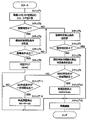
- the vehicle height adjustment control process by the controller 26 will be described with reference to FIGS. Note that the vehicle height adjustment control process shown in FIG. 3 is activated, for example, with the start of vehicle height adjustment, and is repeatedly executed at preset time intervals.
- SB determination in the snow bank determination (hereinafter referred to as SB determination), it is determined whether or not the vehicle body 1 rides on an obstacle that is an external contacted object on the ground side.
- GC determination garage sealing determination
- step 1 the vehicle height H and pressure P are read by detection signals from the vehicle height sensor 16 and the pressure sensor 17.
- the battery voltage V is also read by the detection signal from the voltage sensor 22.
- the vehicle height change as a rate of change of the vehicle height H per unit time.
- the rate ⁇ H is calculated.
- the pressure change rate ⁇ P is calculated as the rate of change of the pressure P per unit time based on, for example, the difference between the previous pressure P and the current pressure P.
- step 2 it is determined whether or not SB determination or GC determination is being performed.
- SB determination or GC determination since it is the start time of the vehicle height adjustment control process, the processes after step 6 are executed.
- step 3 the process proceeds to step 3 because the vehicle height adjustment control process is being executed.
- step 3 conditions for canceling the collision determination (SB determination and GC determination) against the obstacle are calculated.
- a vehicle speed for example, 5 km / h
- a condition for determining the power OFF state is set. Note that the value of the vehicle speed for determining whether or not the vehicle is in a running state is not limited to the exemplified value, and is set as appropriate.
- step 4 it is determined whether or not the release condition set in step 3 is satisfied. Specifically, the controller 26 determines whether the vehicle is in a traveling state or whether the power source is in an OFF state.
- Step 4 when it is determined as “NO” in Step 4, the release condition is not satisfied. Specifically, the vehicle is stopped and the power is turned on. For this reason, the process proceeds to step 6 to calculate the collision determination prohibition condition.
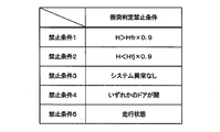
- the prohibition condition 1 is that the vehicle height H detected by the vehicle height sensor 16 is higher than 90% of the fully extended vehicle height Hfr of the air suspension 3 (H> Hfr ⁇ 0.9).
- the prohibition condition 2 is that the vehicle height H is lower than 90% of the retracted vehicle height Hfj of the air suspension 3 (H ⁇ Hfj ⁇ 0.9).
- the prohibition condition 3 is that there is no abnormality in the system.
- the prohibition condition 4 is that any door of the vehicle is open.
- the prohibition condition 5 is that the vehicle is traveling.
- the value that determines whether or not the vehicle height H is near the full vehicle height Hfr is not limited to 90% of the full vehicle height Hfr.
- the value that determines whether or not the vehicle height H is near the shrunken vehicle height Hfj is not limited to 90% of the shrunken vehicle height Hfj.
- Step 7 it is determined whether or not the collision determination is prohibited. Specifically, the controller 26 determines whether or not at least one of the prohibition conditions 1 to 5 set in step 6 is satisfied.
- Step 7 When it is determined as “YES” in Step 7, since any one of the prohibition conditions 1 to 5 is satisfied, the controller 26 maintains the target vehicle height Ht at the current value, and proceeds to Step 13.
- Step 7 when “NO” is determined in Step 7, all of the prohibition conditions 1 to 5 are not satisfied, so that the collision determination is possible. Therefore, the process proceeds to step 8 to calculate threshold values ⁇ Hsb1, ⁇ Hgc1, ⁇ Psb1, and ⁇ Pgc1 used in SB determination and GC determination.
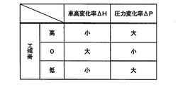
- FIG. 7 shows an example of the relationship between the vehicle height H and the change rates ⁇ H and ⁇ P.
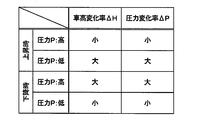
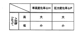
- the threshold values ⁇ Hsb1 and ⁇ Hgc1 of the vehicle height change rate ⁇ H and the threshold values ⁇ Psb1 and ⁇ Pgc1 of the pressure change rate ⁇ P are based on the current vehicle height H, pressure P, and battery voltage V in consideration of the characteristics shown in FIGS. Calculated.
- the threshold value ⁇ Hgc1 of the vehicle height change rate ⁇ H and the threshold value ⁇ Pgc1 of the pressure change rate ⁇ P used for the GC determination are calculated based on the current vehicle height H, pressure P, and battery voltage V.
- the threshold value ⁇ Hsb1 of the vehicle height change rate ⁇ H and the threshold value ⁇ Psb1 of the pressure change rate ⁇ P used for the SB determination are calculated based on the current vehicle height H and pressure P.
- the snow bank is generated when the vehicle height H is lowered.
- the air compressor module 5 is not driven and the exhaust valve 12 is opened to discharge the compressed air into the atmosphere. . For this reason, it is not necessary to consider the battery voltage V when calculating the thresholds ⁇ Hsb1 and ⁇ Psb1 used for the SB determination.
- the battery voltage V is taken into account when calculating the threshold values ⁇ Hsb1 and ⁇ Psb1 used for the SB determination. There is a need to.
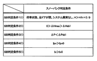
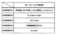
- step 8 in addition to the threshold values ⁇ Hsb1, ⁇ Hgc1, ⁇ Psb1, and ⁇ Pgc1, a collision determination condition is calculated. Specifically, SB determination conditions 1 (1) to 5 (1) shown in FIG. 5 and GC determination conditions 1 (1) to 5 (1) shown in FIG. 6 are set.
- SB determination condition 1 (1) is that when the vehicle is stopped, all doors are closed, the system is normal, and the detected vehicle height H is higher than 90% of the fully extended vehicle height Hfr of the air suspension 3 ( H> Hfr ⁇ 0.9).
- the SB determination condition 2 (1) is that the maximum value ⁇ Hmax of the vehicle height change rate ⁇ H is a negative value and larger than the threshold value ⁇ Hsb1 (0> ⁇ Hmax> ⁇ Hsb1).
- the SB determination condition 3 (1) is that the pressure change rate ⁇ P is smaller than the threshold value ⁇ Psb1 ( ⁇ P ⁇ Psb1).
- GC determination condition 1 (1) is that when the vehicle is stopped, all the doors are closed, the system is normal, and the detected vehicle height H is lower than 90% of the retracted vehicle height Hfj of the air suspension 3 ( H ⁇ Hfj ⁇ 0.9).
- the GC determination condition 2 (1) is that the minimum value ⁇ Hmin of the vehicle height change rate ⁇ H is a positive value and smaller than the threshold value ⁇ Hgc1 (0 ⁇ Hmin ⁇ Hgc1).
- the GC determination condition 3 (1) is that the pressure change rate ⁇ P is larger than the threshold value ⁇ Pgc1 ( ⁇ P> ⁇ Pgc1).
- the GC determination condition 4 (1) is that the drive command for the air compressor 6 is ON (output state).
- the maximum value ⁇ Hmax and the minimum value ⁇ Hmin of the vehicle height change rate ⁇ H indicate the maximum value and the minimum value of the vehicle height change rate ⁇ H calculated within the current control cycle. Further, specific numerical values of the drive current values Ipv0 and Iv0 are examples, and are set as appropriate for each actual vehicle.
- the fixed time is set to a short time (for example, 2 seconds), and after the garage sealing is determined by the previous detection. Is set to a long time (for example, 10 seconds).
- step 9 determines whether or not all the GC determination conditions 1 (1) to 5 (1) are satisfied over a certain period of time.
- the fixed time is set to a short time (for example, 2 seconds) in a state where neither the snow bank nor the garage sealing is determined, and a long time (for example, 10 seconds) after the snow bank is determined by the previous detection. Second).
- the fixed time is not limited to the exemplified numerical values, and is set as appropriate in consideration of the occurrence of erroneous determination.
- Step 11 when it is determined as “NO” in Step 11, it is considered that neither the snow bank nor the garage sealing has occurred. Therefore, the process proceeds to step 13 in a state where the target vehicle height Ht is held at the current value.
- step 13 the controller 26 performs vehicle height adjustment so that the target vehicle height Ht is obtained. That is, the controller 26 raises the vehicle body 1 when the target vehicle height Ht is higher than the current vehicle height H. On the other hand, when the target vehicle height Ht is lower than the current vehicle height H, the controller 26 lowers the vehicle body 1. When the target vehicle height Ht is close to the current vehicle height H, the controller 26 stops the raising and lowering of the vehicle body 1 and maintains the current vehicle height H.
- FIG. 12A shows a state where the vehicle body 1 is lowered by adjusting the vehicle height.
- the controller 26 opens the exhaust valve 12 and the supply / exhaust valve 15. Thereby, since air is discharged from the air suspension 3, the air suspension 3 is reduced and the vehicle body 1 is lowered.
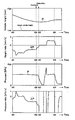
- the vehicle height H decreases as shown between times t01 and t02 in FIG.
- the pressure P tends to decrease (negative value), but the change is relatively small.
- FIG. 12B shows a state in which a snow bank has occurred while the vehicle body 1 is descending.
- the obstacle 1 prevents the vehicle body 1 from descending.
- the vehicle height H is fixed at a constant value and the pressure P starts to greatly decrease compared to before the collision of the obstacle.
- the controller 26 determines that the snow bank.
- the controller 26 stops the vehicle height adjustment operation and displaces the vehicle body 1 by the collision avoidance amount dh in the direction opposite to the descending operation (upward direction). Specifically, the controller 26 switches the exhaust valve 12 from opening to closing, and then drives the air compressor module 5 to supply compressed air to the air suspension 3. As a result, the pressure P increases and the vehicle height H increases as shown between times t03 and t04 in FIG. As a result, as shown in FIG. 12C, the vehicle body 1 rises and leaves the obstacle, so that the vehicle can move.
- FIG. 12C shows a state in which the vehicle body 1 is raised after the snow bank is detected.
- FIG. 13A shows a state in which the vehicle body 1 is raised by adjusting the vehicle height.
- the controller 26 closes the exhaust valve 12 and opens the air supply / exhaust valve 15. Then, the air compressor module 5 is driven. Thereby, since compressed air is supplied to the air suspension 3, the air suspension 3 extends and the vehicle body 1 moves up. At this time, the vehicle height H increases as shown between times t11 and t12 in FIG. On the other hand, the pressure P tends to increase (positive value), but its change is relatively small.
- FIG. 13B shows a state in which garage sealing has occurred while the vehicle body 1 is being raised.
- the obstacle prevents the vehicle body 1 from rising.
- the vehicle height H is fixed at a constant value and the pressure P starts to increase greatly as compared to before the collision of the obstacle.
- the minimum value ⁇ Hmin of the vehicle height change rate ⁇ H becomes smaller than the threshold value ⁇ Hgc1, and the pressure change rate ⁇ P increases more than the threshold value ⁇ Pgc1. If this state continues for a certain period of time or longer, the controller 26 determines that the garage sealing is being performed.
- the controller 26 stops the vehicle height adjustment operation and displaces the vehicle body 1 by the collision avoidance amount dh in the direction opposite to the ascending operation (downward direction). Specifically, the controller 26 opens the exhaust valve 12 and discharges air from the air suspension 3. As a result, the pressure P decreases and the vehicle height H decreases as shown between times t13 and t14 in FIG. As a result, as shown in FIG. 13C, the vehicle body 1 descends and leaves the obstacle, so that the vehicle can move.
- FIG. 13C shows a state where the vehicle body 1 is lowered after detection of the garage sealing.
- the vehicle height adjusting device of the first embodiment when the controller 26 determines that the movement of the vehicle body 1 is restricted by the vehicle height sensor 16 and the pressure sensor 17, the vehicle height sensor 16 and the pressure sensor 17. Based on the detected value (vehicle height H, pressure P), the movement of the vehicle body 1 upward or downward is stopped so that the movement of the vehicle body 1 is restricted, and the movement is switched to the reverse direction. As a result, the collision between the vehicle body 1 and the object can be detected with high accuracy even when the obstacle, which is an external contacted body, is disposed at any position above and below the vehicle body 1. In addition to this, when the movement of the vehicle body 1 is restricted, the vehicle body 1 is moved in the direction opposite to the vehicle height adjustment movement direction. Can be made possible.
- the threshold values ⁇ Hsb1 and ⁇ Psb1 used in the SB determination and the threshold values ⁇ Hgc1 and ⁇ Pgc1 used in the GC determination are changed according to the pressure P and the vehicle height H. For this reason, the SB determination and the GC determination can be performed in consideration of the characteristics of the air spring 4 and the bump rubber characteristics.
- the controller 26 determines SB and GC. It was decided not to do. For example, when the air spring 4 is in a high pressure state, the vehicle height H may slightly decrease even when the exhaust operation is performed. In addition, when the air spring 4 is in an extremely low pressure state, the vehicle height H may slightly increase even if the air supply operation is performed. Since the collision with the obstacle is not determined when the change in the vehicle height H is small as described above, erroneous determination can be suppressed.
- the controller 26 prohibits the determination of the collision with the obstacle in the situation where the erroneous determination is assumed as shown in the prohibition conditions 3 to 5. For this reason, erroneous determination can be suppressed.
- FIG. 1 to FIG. 4, FIG. 14 and FIG. 15 show a second embodiment of the present invention.
- the feature of the second embodiment is that the vehicle height change rate and pressure change rate threshold values used for collision determination are calculated based on the vehicle height change rate and pressure change rate measured in the past.
- the same components as those in the first embodiment are denoted by the same reference numerals, and the description thereof is omitted.
- the controller 31 according to the second embodiment is configured in substantially the same manner as the controller 26 according to the first embodiment. For this reason, the storage unit 31A of the controller 31 stores a vehicle height adjustment control processing program and the like shown in FIG. 3 as in the first embodiment. The controller 31 executes a vehicle height adjustment control process shown in FIG.
- the controller 31 replaces the SB determination conditions 1 (1) to 5 (1) and the GC determination conditions 1 (1) to 5 (1) according to the first embodiment with reference to FIG. SB determination conditions 1 (2) to 5 (2) shown in FIG. 5 and GC determination conditions 1 (2) to 5 (2) shown in FIG. 15 are set.
- the SB determination conditions 1 (2), 4 (2), 5 (2) according to the second embodiment are the SB determination conditions 1 (1), 4 (1), 5 according to the first embodiment. Same as (1).
- the GC determination conditions 1 (2), 4 (2), 5 (2) according to the second embodiment are the GC determination conditions 1 (1), 4 (1), 5 (1) according to the first embodiment. Is the same.
- the thresholds ⁇ Hsb2 and ⁇ Psb2 used in the SB determination conditions 2 (2) and 3 (2) and the thresholds ⁇ Hgc2 and ⁇ Pgc2 used in the GC determination conditions 2 (2) and 3 (2) are This is different from the threshold values ⁇ Hsb1, ⁇ Hgc1, ⁇ Psb1, and ⁇ Pgc1 used in the first embodiment.
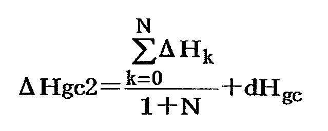
- the threshold values ⁇ Hsb2 and ⁇ Hgc2 are calculated based on the following formulas 1 and 2 by averaging the past vehicle height variation ⁇ H.
- the change amount ⁇ H is shown.
- the threshold value ⁇ Hsb2 indicates a value obtained by adding the margin dHsb to the average value of the vehicle height change amount ⁇ H for the total (N + 1) times obtained by adding the current N times to the past N times.
- the threshold value ⁇ Hgc2 indicates a value obtained by adding the margin dHgc to the average value of the vehicle height change amount ⁇ H for the total (N + 1) times obtained by adding the current N to the past N times.
- the margins dHsb and dHgc are set in advance in consideration of, for example, a vehicle height change amount ⁇ H obtained with an actual vehicle.
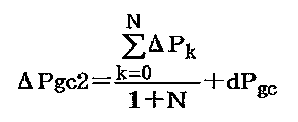
- the threshold value ⁇ Psb2 indicates a value obtained by adding the margin dPsb to the average value of the pressure change amount ⁇ P for the total (N + 1) times obtained by adding the current N to the past N times.
- the threshold value ⁇ Pgc2 indicates a value obtained by adding the margin dPgc to the average value of the pressure change amount ⁇ P for the total (N + 1) times obtained by adding the current N times to the past N times.
- the margins dPsb and dPgc are set in advance in consideration of, for example, the pressure change amount ⁇ P obtained in an actual vehicle.
- the number of past vehicle height change amounts ⁇ H and pressure change amounts ⁇ P (N times) used to calculate the threshold values ⁇ Hsb2, ⁇ Hgc2, ⁇ Psb2, and ⁇ Pgc2 is appropriately set in consideration of the occurrence of erroneous determination. is there.
- Step 11 the controller 31 determines whether or not all the GC determination conditions 1 (2) to 5 (2) are satisfied over a certain period of time. If “YES” is determined in the step 11, the process proceeds to the step 12.
- the controller 31 holds the target vehicle height Ht at the current value.
- the vehicle height change amount ⁇ H and the pressure change amount ⁇ P change under various conditions such as the vehicle height H, the pressure P, the battery voltage V, and the like. Therefore, in the first embodiment, the determination thresholds ⁇ Hsb1, ⁇ Hgc1, ⁇ Psb1, and ⁇ Pgc1 are calculated based on various conditions such as the vehicle height H, the pressure P, the battery voltage V, and the like. .
- threshold values ⁇ Hsb2, ⁇ Hgc2, ⁇ Psb2, and ⁇ Pgc2 used for SB determination and GC determination are sequentially set based on the actually measured vehicle height change amount ⁇ H and pressure change amount ⁇ P.
- the controller 31 stores a vehicle height change amount ⁇ H and a pressure change amount ⁇ P since the start of the vehicle height adjustment, and based on the stored past vehicle height change amount ⁇ H and pressure change amount ⁇ P.
- the current threshold values ⁇ Hsb2, ⁇ Hgc2, ⁇ Psb2, and ⁇ Pgc2 are determined. For this reason, it is not necessary to consider various conditions.
- the threshold values ⁇ Hsb2, ⁇ Hgc2, ⁇ Psb2, and ⁇ Pgc2 it is necessary to store the past vehicle height change amount ⁇ H and the pressure change amount ⁇ P over a predetermined time. Contact cannot be detected. Therefore, at the start of the vehicle height adjustment, the threshold values ⁇ Hsb1, ⁇ Hgc1, ⁇ Psb1, ⁇ Pgc1 according to the first embodiment are used, and after a certain time has elapsed, the threshold values ⁇ Hsb2, ⁇ Hgc2, ⁇ Psb2, It may be switched to ⁇ Pgc2.
- FIGS. 1 to 4 and FIGS. 16 to 17 show a third embodiment of the present invention.
- a feature of the third embodiment resides in that SB determination and GC determination are performed based on a value obtained by dividing the pressure change rate by the vehicle height change rate. Note that in the third embodiment, the same components as those in the first embodiment described above are denoted by the same reference numerals, and description thereof is omitted.
- the controller 41 according to the third embodiment is configured in substantially the same manner as the controller 26 according to the first embodiment. For this reason, the storage unit 41A of the controller 41 stores a vehicle height adjustment control processing program and the like shown in FIG. 3 as in the first embodiment. The controller 41 executes a vehicle height adjustment control process shown in FIG.
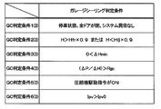
- the controller 41 replaces the SB determination conditions 1 (1) to 5 (1) and the GC determination conditions 1 (1) to 5 (1) according to the first embodiment with step 6 in FIG. And SB determination conditions 1 (3) to 6 (3) shown in FIG. 17 and GC determination conditions 1 (3) to 6 (3) shown in FIG.
- SB judgment condition 1 (3) is that all doors are closed and there is no abnormality in the system when the vehicle is stopped.
- the SB determination condition 2 (3) is that the detected vehicle height H is higher than 90% of the fully extended vehicle height Hfr of the air suspension 3 (H> Hfr ⁇ 0.9), or the detected vehicle height H Is lower than 90% of the contraction wheel height Hfj of the air suspension 3 (H ⁇ Hfj ⁇ 0.9).
- the SB determination condition 3 (3) is that the maximum value ⁇ Hmax of the vehicle height change rate ⁇ H is a negative value (0> ⁇ Hmax).
- a value ( ⁇ P / ⁇ H) obtained by dividing the pressure change rate ⁇ P by the vehicle height change rate ⁇ H is larger than a threshold value Rsb determined based on the vehicle height H and the pressure P (Rsb ⁇ ⁇ P / ⁇ H).
- GC determination condition 1 (3) is that all doors are closed and there is no abnormality in the system when the vehicle is stopped.
- the GC determination condition 2 (3) is that the detected vehicle height H is higher than 90% of the fully extended vehicle height Hfr of the air suspension 3 (H> Hfr ⁇ 0.9), or the detected vehicle height H Is lower than 90% of the contracted vehicle height Hfj of the air suspension 3 (H> Hfj ⁇ 0.9).
- the GC determination condition 3 (3) is that the minimum value ⁇ Hmin of the vehicle height change rate ⁇ H is a positive value (0 ⁇ Hmin).
- a value ( ⁇ P / ⁇ H) obtained by dividing the pressure change rate ⁇ P by the vehicle height change rate ⁇ H is larger than a threshold value Rgc determined based on the vehicle height H and the pressure P (Rgc ⁇ ⁇ P / ⁇ H).
- the GC determination condition 5 (3) is that the drive command for the air compressor 6 is ON (output state).
- the storage unit 41A of the controller 41 stores a map of the threshold values Rsb and Rgc. Therefore, the controller 41 calculates the threshold values Rsb and Rgc based on the current vehicle height H and pressure P. At this time, the threshold values Rsb and Rgc may be the same value or different values. The threshold values Rsb and Rgc may be set sequentially based on the actually measured vehicle height change amount ⁇ H and pressure change amount ⁇ P. In this case, the accuracy of SB determination and GC determination can be improved.
- Step 11 the controller 41 determines whether or not all the GC determination conditions 1 (3) to 6 (3) are satisfied over a certain period of time. If “YES” is determined in the step 11, the process proceeds to the step 12.
- the controller 41 holds the target vehicle height Ht at the current value.
- the controller 41 uses the pressure change rate ⁇ P based on the detection value (pressure P) detected by the pressure sensor 17 as the vehicle height change rate based on the detection value (vehicle height H) detected by the vehicle height sensor 16. It is determined that the upward or downward movement of the vehicle body 1 is restricted by the value divided by ⁇ H. For this reason, since it does not depend on the performance of the air compressor 6, for example, the robustness of the vehicle height adjusting device can be improved.
- the SB determination condition 5 (3) is such that the current command Ipv of the air supply / exhaust valve 15 is larger than the predetermined drive current value Ipv0 (Ipv> Ipv0).
- the present invention is not limited to this.
- the state where the current command Ipv of the supply / exhaust valve 15 is larger than the drive current value Ipv0 (Ipv> Ipv0) continues for a predetermined time.
- This may be one of the SB determination conditions.
- the predetermined time is set to a value (for example, 10 seconds) obtained by adding a margin (for example, 3 seconds) to a maximum time (for example, 7 seconds) in which the vehicle height does not change in the actual vehicle.
- step 9 in FIG. 3 it is determined whether or not all the SB determination conditions are satisfied over a certain period of time.
- the fixed time is set to a short time (for example, 2 seconds) in a state where neither the snow bank nor the garage sealing is determined.
- the initial determination is made for a certain period of time from the time obtained by adding a margin (for example, 1 second) to the maximum time (for example, 12 seconds) from the collision to the obstacle. It is set to a value (for example, 3 seconds) obtained by subtracting a predetermined time (for example, 10 seconds).
- a margin for example, 1 second
- the maximum time for example, 12 seconds
- a predetermined time for example, 10 seconds
- the GC determination condition 5 (3) is such that the current command Ipv of the supply / exhaust valve 15 is larger than the predetermined drive current value Ipv0 (Ipv> Ipv0).
- the present invention is not limited to this.
- a state where the current command Ipv of the supply / exhaust valve 15 is larger than the drive current value Ipv0 (Ipv> Ipv0) continues for a predetermined time.
- This may be one of the SB determination conditions.
- the predetermined time is set to a value (for example, 10 seconds) obtained by adding a margin (for example, 3 seconds) to the maximum time (for example, 7 seconds) in which the vehicle height does not change in the actual vehicle.
- step 11 in FIG. 3 it is determined whether or not all the GC determination conditions are satisfied over a certain period of time.
- the fixed time is set to a short time (for example, 2 seconds) in a state where neither the snow bank nor the garage sealing is determined.
- the predetermined time is set to a time (for example, 3 seconds) in consideration of a predetermined time that is an initial determination time as in the SG determination condition.
- a GC determination can also be applied to the first and second embodiments.
- a collision determination prohibition condition a case where a garage ceiling is detected after detecting a snow bank and a case where a snow bank is detected after detecting a garage ceiling may be added. The reason for this is to prevent the snow bank and garage sealing from being repeatedly determined. Such prohibition of collision determination can also be applied to the first and second embodiments.
- steps 6 and 7 in FIG. 3 show a specific example of the collision determination prohibiting means
- steps 8, 9, and 11 show a specific example of the collision determination means.
- the same controller 26, 31, 41 executes the collision determination with the obstacle and the control of the air suspension 3.
- the present invention is not limited to this, and a separate controller may execute the collision determination with the obstacle and the control of the air suspension. That is, the controllers 26, 31, and 41 may control the air suspension 3 based on the determination result by a separate controller.
- the air suspension 3 is provided on the rear wheels 2C and 2D.
- the present invention is not limited to this, and air suspensions may be provided on all the wheels 2A to 2D, or air suspensions may be provided only on the front wheels.
- the pneumatic suspension device including the air compressor module 5 and the air suspension 3 as a fluid pressure device has been described as an example.
- the present invention is not limited to this, and may be applied to, for example, a hydraulic suspension device including a hydraulic pump and a hydraulic damper or hydraulic cylinder as a fluid pressure device.
- the present invention may be applied to an electromagnetic suspension capable of adjusting the vehicle height by a magnetic force.
- a current supplied to the electromagnetic suspension may be detected as a physical quantity relating to the restriction on the upward or downward movement of the vehicle body. That is, the detection device may be configured by a current sensor that detects a current supplied to the electromagnetic suspension.
- the air suspension device is applied to a vehicle of a four-wheel automobile.
- the present invention is not limited to this, and may be applied to other vehicles such as railway vehicles.
- a vehicle height adjustment actuator that is provided on at least a pair of front wheels or a pair of rear wheels among a plurality of wheels of the vehicle and adjusts a vehicle height that is a distance between the wheels and the vehicle body, and the vehicle height adjustment actuator,
- An actuator control device that controls the vehicle height to approach the target vehicle height, and a detection device that detects a physical quantity that changes when the vehicle body is restricted from moving upward or downward by contact with an external contacted body.
- the actuator control device stops moving the vehicle body upward or downward based on the detection value of the detection device when it is determined that the movement of the vehicle body is restricted by the detection device. And it was set as the structure switched to the movement to a reverse direction.
- the vehicle height adjusting actuator is a fluid pressure device that adjusts the vehicle height by a fluid pressure
- the detection device is a vehicle height detection device, and a pressure detection device that detects a fluid pressure acting on the fluid pressure device
- the actuator control device based on a pressure change rate calculated from a detection value detected by the pressure detection device and a vehicle height change rate calculated from a detection value detected by the vehicle height detection device, It is configured to determine whether or not the movement of the vehicle body is restricted upward or downward. At this time, the relationship between the vehicle height change rate and the pressure change rate changes depending on whether or not the vehicle body collides with an obstacle. For this reason, the collision between the vehicle body and the obstacle can be detected based on the relationship between the vehicle height change rate and the pressure change rate.
- the actuator control device includes: a threshold value of the pressure change rate calculated based on a detection value detected by the pressure detection device and a detection value detected by the vehicle height detection device; and a detection value detected by the pressure detection device.
- the vehicle height change rate threshold value calculated based on the detection value detected by the vehicle height detection device is used to determine whether or not movement of the vehicle body is restricted upward or downward. . For this reason, the characteristics of the fluid pressure device can be taken into consideration.
- the actuator control device uses a threshold value for the pressure change rate calculated from the pressure change rate detected in the past and a threshold value for the vehicle height change rate calculated from the vehicle height change rate detected in the past. Thus, it is determined whether the upward or downward movement of the vehicle body is restricted. At this time, the pressure change rate and the vehicle height change rate change based on various conditions such as pressure and vehicle height. On the other hand, since the threshold values of the pressure change rate and the vehicle height change rate are calculated from the values detected in the past, it is not necessary to consider various conditions.
- the vehicle height adjusting actuator is a fluid pressure device that adjusts the vehicle height by a fluid pressure
- the detection device is a vehicle height detection device, and a pressure detection device that detects a fluid pressure acting on the fluid pressure device
- the actuator control device includes a value obtained by dividing a pressure change rate calculated from a detection value detected by the pressure detection device by a vehicle height change rate calculated from the detection value detected by the vehicle height detection device. Based on this, it is determined whether or not the movement of the vehicle body is restricted upward or downward. For this reason, for example, since it does not depend on the performance of the supply source of fluid pressure, the robustness of the vehicle height adjusting device can be improved.
- the determination threshold for the value obtained by dividing the pressure change rate by the vehicle height change rate is sequentially set based on the actually measured vehicle height change amount and pressure change amount. Thereby, the determination precision of a contact with an obstacle can be improved.
Landscapes
- Engineering & Computer Science (AREA)
- Mechanical Engineering (AREA)
- Vehicle Body Suspensions (AREA)
Abstract
車体と物体との衝突を精度良く検出する。 車高調整装置は、車両の複数の車輪のうち少なくとも、一対の前輪または一対の後輪に設けられ、車輪と車体との間の距離である車高を調整する車高調整アクチュエータと、車高調整アクチュエータを、車高が目標車高に近づくように制御するアクチュエータ制御装置と、車体が外部の被接触体との接触により上方または下方への移動が制限されたときに変化する物理量を検出する検出装置と、を備える。アクチュエータ制御装置は、検出装置により車体の移動が制限されたと判断されたときに、検出装置の検出値に基づいて、上方または下方への前記車体の移動を停止し、逆方向への移動に切換える。
Description
本発明は、例えば4輪自動車等の車両に搭載されて好適な車高調整装置に関する。
特許文献1には、車高調整の開始前または調整中に、車両の設定領域内に物体が存在することが検出された場合には、車高調整を中止する車高調整装置が開示されている。
ところで、特許文献1に記載された車高調整装置では、クリアランスソナー、ミリ波レーダ等からなる周囲物体検出装置を車両の4隅に設け、これらの周囲物体検出装置を用いて物体の存在を検出している。このため、例えば車両の直下に障害物が進入したときには、物体を検出することができないことがある。この状態で、車高を低下させると、車体の底が物体に衝突して、車輪が浮き上がる傾向がある。駆動輪が浮き上がってしまった場合には、駆動力が得られず、発進できなくなる虞れがある。
また、特許文献1に記載された周囲物体検出装置では、車両の前方または下方について物体の検出を行うが、車両の上方については物体の検出を行っていない。このため、例えば車両が天井の低い車庫に進入した状態で、車高を上昇させた場合には、車体の上部が車庫の天井に衝突してしまうという問題もある。
本発明の目的は、車体と物体との衝突を精度良く検出することができる車高調整装置を提供することにある。
本発明の一実施形態による車高調整装置は、車両の複数の車輪のうち少なくとも、一対の前輪または一対の後輪に設けられ、前記車輪と車体との間の距離である車高を調整する車高調整アクチュエータと、前記車高調整アクチュエータを、前記車高が目標車高に近づくように制御するアクチュエータ制御装置と、前記車体が外部の被接触体との接触により上方または下方への移動が制限されたときに変化する物理量を検出する検出装置と、を備え、前記アクチュエータ制御装置は、前記検出装置により前記車体の移動が制限されたと判断されたときに、前記検出装置の検出値に基づいて、前記上方または下方への前記車体の移動を停止し、逆方向への移動に切換える。
本発明の一実施形態によれば、車体と物体との衝突を精度良く検出することができる。
以下、本発明の実施の形態による車高調整装置を、4輪自動車等の車両に搭載する場合を例に挙げ、添付図面に従って詳細に説明する。
まず、図1ないし図6は本発明の第1の実施の形態を示している。図1において、車両のボディを構成する車体1の下側(路面側)には、左前および右前の車輪2A,2B(前輪)と、左後および右後の車輪2C,2D(後輪)とが設けられている。
エアサスペンション3は、流体圧力(空圧)により車高Hを調整する流体圧力装置を構成している。エアサスペンション3は、車両の4個の車輪2A~2Dのうち後方に位置する2個の車輪2C,2D(後輪)にそれぞれ設けられている。具体的には、エアサスペンション3は、車両の車体1と車輪2C,2Dとの間に介在し、2個の車輪2C,2Dにそれぞれ対応するように2個設けられている。また、エアサスペンション3は、エアばね4を備えている。エアサスペンション3は、車高調整アクチュエータを構成している。このため、エアサスペンション3は、作動流体としての空気が供給または排出されることによって、車輪2C,2Dと車体1との間の距離である車高Hを調整するものである。
エアばね4は、分岐管路14A,14Bと給排気バルブ15とを介して圧縮エアが供給または排出されると、このときの給排量(エア量)に応じて上下方向に伸長または縮小される。これにより、エアサスペンション3は、車体1の車高調整を個別に行い、各車輪2C,2D毎に車高が上昇または下降されるものである。
エアコンプレッサモジュール5は、空気圧縮機6および電動モータ7を備え、バッテリ21からの電力供給により動作する油空圧ポンプを構成している。エアコンプレッサモジュール5は、例えば車体1の後部側に搭載され、エアサスペンション3のエアばね4に圧縮エアを供給する。
空気圧縮機6は、例えば往復動圧縮機またはスクロール式圧縮機等により構成されている。空気圧縮機6の吸込み側と吐出側には、チェック弁6Aがそれぞれ設けられている。空気圧縮機6は、駆動源としての電動モータ7により駆動され、吸込フィルタ8側から吸込んだ外気または大気を圧縮して圧縮エア(エア)を発生させる。吸込フィルタ8は、吸込音を低減するサイレンサとしても機能する。
給排管路9は、空気圧縮機6の吐出側に接続して設けられている。図2に示すように、給排管路9の一側(基端側)は、空気圧縮機6の吐出側に接続され、給排管路9の他側(先端側)はエアコンプレッサモジュール5の外部まで延びている。給排管路9の先端側には、分岐管路14A,14Bが接続されている。
エアドライヤ10は、給排管路9の途中に介装して設けられ、空気を乾燥させるものである。このエアドライヤ10は、例えば水分吸着剤(図示せず)等を内蔵し、スローリターンバルブ11と排気管路13との間に配設されている。スローリターンバルブ11は、絞り11Aとチェック弁11Bとの並列回路により構成され、空気圧縮機6からエアサスペンション3に向かう順方向の流れに対しては、チェック弁11Bが開弁して圧縮エアの流量を絞ることはない。一方、逆方向の流れに対してはチェック弁11Bが閉弁し、このときの圧縮エアは絞り11Aにより流量が絞られるために、エアドライヤ10内をゆっくりと小流量で逆流するものである。
エアドライヤ10は、空気圧縮機6で発生した圧縮エアがエアサスペンション3側に向けて順方向に流通するときに、この圧縮エアを内部の水分吸着剤に接触させることにより水分を吸着し、乾燥した圧縮エアをエアばね4に向けて供給する。一方、エアばね4から排出された圧縮エア(排気)がエアドライヤ10内を逆方向に流通するときには、乾燥したエアがエアドライヤ10内を逆流する。このとき、エアドライヤ10内の水分吸着剤は、この乾燥エアにより水分が脱着される。これにより、水分吸着剤は再生され、再び水分を吸着可能な状態に戻される。
排気バルブ12(排気弁)は、エアコンプレッサモジュール5(空気圧縮機6)の吐出側の空気(作動流体)を排出する。排気バルブ12は、排気管路13を介して給排管路9に接続されている。この排気バルブ12は、ソレノイド(コイル)12Aを備え、例えば2ポート2位置の電磁式切換弁(スプリングオフセット式の常閉弁)によって構成されている。排気バルブ12は、常時は閉弁して排気管路13を遮断している。排気バルブ12のソレノイド12Aがコントローラ26からの通電により励磁されると、排気バルブ12は、開弁して排気管路13を連通させる。これにより、排気バルブ12は、給排管路9内の圧縮エアを大気中に排出(放出)するものである。
分岐管路14A,14Bは、車輪2C,2Dに応じて給排管路9から2つに分岐し、車輪2C,2Dのエアサスペンション3に向けて延びている。これら2本の分岐管路14A,14Bは、エアコンプレッサモジュール5からエアサスペンション3のエアばね4との間を接続している。分岐管路14A,14Bは、エアばね4を給排管路9に対して接続するため、給排管路9の先端部分から分岐している。
給排気バルブ15(給排気弁)は、エアコンプレッサモジュール5とエアサスペンション3の間に設けられている。具体的には、給排気バルブ15は、エアコンプレッサモジュール5の空気圧縮機6とエアサスペンション3のエアばね4との間に位置して、2本の分岐管路14A,14Bにそれぞれ設けられている。この給排気バルブ15は、排気バルブ12と同様に構成されている。即ち、給排気バルブ15は、ソレノイド15Aを備え、例えば2ポート2位置の電磁式切換弁によって構成されている。このとき、給排気バルブ15は、スプリングオフセット式の常閉弁として形成されている。なお、本実施の形態では、給気バルブと排気バルブとが一体となった給排気バルブ15を用いた構成について説明するが、給気バルブと排気バルブとを別々に設けてもよい。
ここで、ソレノイド15Aは、コントローラ26に電気的に接続されている。給排気バルブ15は、コントローラ26からソレノイド15Aに給電されることにより、ばね力に抗してプランジャ(図示せず)を吸引(移動)し、開弁する。この開弁状態では、エアサスペンション3に対し圧縮エアを供給または排出することができる。一方、給排気バルブ15は、ソレノイド15Aへの給電を停止することにより、ばね力により閉弁する。この閉弁状態では、給排気バルブ15は、エアサスペンション3に対する圧縮エアの供給や排出を停止することができる。
エアサスペンション3には、車高センサ16が設けられている。車高センサ16は、車体1が外部の被接触体との接触により上方または下方への移動が制限されたときに変化する物理量を検出する検出装置の一部を構成している。即ち、車高センサ16は、車高検出装置であり、エアばね4が拡張または縮小する方向のエアばね4の長さ寸法(上,下方向の寸法)に基づいて、エアサスペンション3の車高H(車高値)を検出する。車高センサ16は、車高Hの検出信号をコントローラ26に出力する。
また、給排管路9には、スローリターンバルブ11と給排気バルブ15との間に位置して、圧力センサ17が設けられている。圧力センサ17は、車体1が外部の被接触体との接触により上方または下方への移動が制限されたときに変化する物理量を検出する検出装置の一部を構成している。即ち、圧力センサ17は、エアサスペンション3に作用する空圧を検出する圧力検出装置である。このため、圧力センサ17は、エアコンプレッサモジュール5(空気圧縮機6)の吐出側の圧縮エア(空気)の圧力P(圧力値)を検出する。具体的には、圧力センサ17は、エアばね4に供給された圧縮エアの圧力Pを検出する。圧力センサ17は、圧力Pの検出信号をコントローラ26に出力する。
次に、空気圧縮機6と電動モータ7を駆動するための電気回路について、図2を参照しつつ説明する。
バッテリ21は、車両に設けられている。電動モータ7の正側の端子は、コンプレッサリレー23とヒューズ24とを介して電源となるバッテリ21に接続されている。バッテリ21には、バッテリ電圧Vを検出する電圧センサ22が接続されている。電圧センサ22は、バッテリ電圧Vを検出することにより、バッテリ電圧Vの検出信号をコントローラ26に出力する。
電動モータ7の負側の端子は、グランドに接続されている。電動モータ7の正側と負側の端子には、突入電流等を抑制するためのチョークコイル7Aがそれぞれ接続されている。また、電動モータ7の正側の端子には、チョークコイル7Aとバッテリ21との間に位置してサーマルリレー25が接続されている。
コンプレッサリレー23(リレー)は、バッテリ21とエアコンプレッサモジュール5との間を接続する。コンプレッサリレー23は、コイル23Aと接点23Bとを備えている。コンプレッサリレー23は、常時は、接点23Bがオフ状態になり、コントローラ26によってコイル23Aに電流が流れたときに、接点23Bがオン状態に切り換わる。コンプレッサリレー23は、接点23Bがオン状態となったときに、バッテリ21とエアコンプレッサモジュール5の電動モータ7との間を接続する。
コントローラ26は、車高Hが目標車高Htに近づくように、エアサスペンション3を制御するアクチュエータ制御装置を構成している。コントローラ26は、空気圧縮機6および電動モータ7からなるエアコンプレッサモジュール5の駆動と停止を制御する。これに加えて、コントローラ26は、排気バルブ12および給排気バルブ15の開弁と閉弁を制御する。コントローラ26の入力側は、車高センサ16、圧力センサ17、電圧センサ22に接続されている。コントローラ26の出力側は、コンプレッサリレー23のコイル23A、排気バルブ12のソレノイド12A、給排気バルブ15のソレノイド15Aに接続されている。
コントローラ26は、例えばROM、RAM、不揮発性メモリ等からなる記憶部26Aを有している。この記憶部26A内には、例えば図3に示す車高調整制御処理のプログラム等が格納されている。コントローラ26は、記憶部26Aに格納されてプログラムを実行することによって、エアサスペンション3を制御し、車両の車高Hを調整する。具体的には、コントローラ26は、車高センサ16、圧力センサ17等から入力される検出信号に基づいて、電動モータ7に供給する電流を制御すると共に、排気バルブ12、給排気バルブ15のソレノイド12A,15Aに供給する電流を制御する。
次に、コントローラ26による車高調整制御処理について、図1ないし図9を参照して説明する。なお、図3に示す車高調整制御処理は、例えば車高調整の開始に伴って起動し、予め設定された時間毎に繰り返し実行される。
また、図3に示す車高調整制御処理において、スノーバンク判定(以下、SB判定という)では、車体1が地面側の外部の被接触体である障害物に乗り上げた否かを判定する。ガレージシーリング判定(以下、GC判定という)では、車体1が上方側の外部の被接触体である障害物に接触したか否かを判定する。
まず、ステップ1では、車高センサ16および圧力センサ17からの検出信号によって、車高Hと圧力Pを読込む。このとき、電圧センサ22からの検出信号によって、バッテリ電圧Vも一緒に読込む。これに加え、例えば記憶された前回の車高Hと、車高センサ16によって検出された今回の車高Hとの差に基づいて、単位時間当りの車高Hの変化率として、車高変化率ΔHを算出する。同様に、例えば前回の圧力Pと今回の圧力Pとの差に基づいて、単位時間当りの圧力Pの変化率として、圧力変化率ΔPを算出する。
続くステップ2では、SB判定またはGC判定を行っている途中か否かを判定する。ステップ2で「NO」と判定したときには、車高調整制御処理の開始時点であるので、ステップ6以降の処理を実行する。一方、ステップ2で「YES」と判定したときには、車高調整制御処理の実行途中であるので、ステップ3に移行する。
ステップ3では、障害物に対する衝突の判定(SB判定およびGC判定)を解除するための条件を計算する。具体的には、車速センサ(図示せず)等からの信号に基づいて、車両が走行状態か否かを決めるための車速(例えば5km/h)を設定する。これに加え、電源のOFF状態を判定する条件を設定する。なお、車両が走行状態か否かを判定する車速の値は、例示した値に限らず、適宜設定される。
続くステップ4では、ステップ3で設定した解除条件が成立したか否かを判定する。具体的に、コントローラ26は、車両が走行状態か否か、または、電源がOFF状態か否かを判定する。
ステップ4で「YES」と判定したときには、解除条件が成立している。具体的には、車両の走行中または電源OFFのいずれかの状態になっている。このため、ステップ5に移行して、SB判定およびGC判定の結果をクリアすると共に、目標車高Htを初期値としてゼロ(Ht=0)に設定する。ステップ5が終了すると、ステップ13に移行する。
一方、ステップ4で「NO」と判定したときには、解除条件は成立していない。具体的には、車両の停車状態で、かつ、電源がON状態になっている。このため、ステップ6に移行して、衝突判定禁止条件を計算する。
具体的には、図4に示すように、以下の禁止条件1~5を設定する。禁止条件1は、車高センサ16によって検出された車高Hがエアサスペンション3の伸び切り車高Hfrの90%よりも高い(H>Hfr×0.9)ことである。禁止条件2は、車高Hがエアサスペンション3の縮み切り車高Hfjの90%よりも低い(H<Hfj×0.9)ことである。禁止条件3は、システムに異常がないことである。禁止条件4は、車両のいずれかのドアが開いていることである。禁止条件5は、車両が走行中であることである。
なお、車高Hが伸び切り車高Hfr付近か否かを決める値は、伸び切り車高Hfrの90%に限らない。同様に、車高Hが縮み切り車高Hfj付近か否かを決める値は、縮み切り車高Hfjの90%に限らない。これらの値は、車高Hfr,Hfjに対するマージンであり、例えば75%~95%の範囲内で、誤判定の発生状況に基づいて適宜設定される。
続くステップ7では、衝突判定が禁止されているか否かを判定する。具体的には、コントローラ26は、ステップ6で設定された禁止条件1~5のうち少なくとも1つの条件を満たしているか否かを判定する。
ステップ7で「YES」と判定したときには、禁止条件1~5のいずれかを満たしているから、コントローラ26は、目標車高Htを現在の値に保持して、ステップ13に移行する。
一方、ステップ7で「NO」と判定したときには、禁止条件1~5の全てを満たしていないから、衝突判定が可能な状態になっている。このため、ステップ8に移行して、SB判定およびGC判定で用いる閾値ΔHsb1,ΔHgc1,ΔPsb1,ΔPgc1を算出する。
ここで、現在の車高H、圧力P、バッテリ電圧Vと、車高変化率ΔH、圧力変化率ΔPとの間には、例えば図7ないし図9に示す関係がある。
即ち、図7に示すように、車高Hが高い位置まで上昇したときには、エアサスペンション3の伸び切りに近付くため、車高変化率ΔHは小さくなり、圧力変化率ΔPは大きくなる。車高Hがゼロ(初期値)付近にあるときには、エアサスペンション3の伸び切りと縮み切りの中間であるため、上昇時と下降時のいずれでも、車高変化率ΔHは大きくなり、圧力変化率ΔPは小さくなる。車高Hが低い位置まで下降したときには、エアサスペンション3の縮み切りに近付くため、車高変化率ΔHは小さくなり、圧力変化率ΔPは大きくなる。なお、車高Hと変化率ΔH,ΔPとの関係は、エアばね4の特性に応じて異なる。このため、図7は、車高Hと変化率ΔH,ΔPとの関係の一例を示したものである。
図8に示すように、車高Hの上昇時に圧力Pが高いときには、車高変化率ΔHと圧力変化率ΔPは、いずれも小さくなる。車高Hの上昇時に圧力Pが低いときには、車高変化率ΔHと圧力変化率ΔPは、いずれも大きくなる。車高Hの下降時に圧力Pが高いときには、車高変化率ΔHと圧力変化率ΔPは、いずれも大きくなる。車高Hの下降時に圧力Pが低いときには、車高変化率ΔHと圧力変化率ΔPは、いずれも小さくなる。なお、圧力Pと変化率ΔH,ΔPとの関係は、エアばね4の特性に応じて異なる。このため、図8は、圧力Pと変化率ΔH,ΔPとの関係の一例を示したものである。
図9に示すように、バッテリ電圧Vが高いときには、エアコンプレッサモジュール5による圧縮エアの供給能力が高くなるため、車高変化率ΔHと圧力変化率ΔPは、いずれも大きくなる。バッテリ電圧Vが低いときには、エアコンプレッサモジュール5による圧縮エアの供給能力が低くなるため、車高変化率ΔHと圧力変化率ΔPは、いずれも小さくなる。
車高変化率ΔHの閾値ΔHsb1,ΔHgc1および圧力変化率ΔPの閾値ΔPsb1,ΔPgc1は、図7ないし図9に示す特性を考慮して、現在の車高H、圧力P、バッテリ電圧Vに基づいて算出される。
即ち、GC判定に用いる車高変化率ΔHの閾値ΔHgc1と圧力変化率ΔPの閾値ΔPgc1は、現在の車高H、圧力P、バッテリ電圧Vに基づいて算出される。一方、SB判定に用いる車高変化率ΔHの閾値ΔHsb1と圧力変化率ΔPの閾値ΔPsb1は、現在の車高H、圧力Pに基づいて算出される。このとき、スノーバンクは車高Hを下降させるときに発生するが、この下降時は、エアコンプレッサモジュール5は駆動せず、排気バルブ12を開弁することによって、圧縮エアを大気中に排出する。このため、SB判定に用いる閾値ΔHsb1,ΔPsb1を算出するときには、バッテリ電圧Vは考慮する必要がない。
なお、空圧回路が閉回路になっており、車高Hの下降時もエアコンプレッサモジュール5を駆動する場合には、SB判定に用いる閾値ΔHsb1,ΔPsb1を算出するときも、バッテリ電圧Vを考慮する必要がある。
また、ステップ8では、閾値ΔHsb1,ΔHgc1,ΔPsb1,ΔPgc1に加えて、衝突判定条件を計算する。具体的には、図5に示すSB判定条件1(1)~5(1)と、図6に示すGC判定条件1(1)~5(1)とを設定する。
SB判定条件1(1)は、停車状態で、全ドアが閉じて、システムに異常がなく、かつ、検出された車高Hがエアサスペンション3の伸び切り車高Hfrの90%よりも高い(H>Hfr×0.9)ことである。SB判定条件2(1)は、車高変化率ΔHの最大値ΔHmaxが、負の値であり、かつ、閾値ΔHsb1よりも大きい(0>ΔHmax>ΔHsb1)ことである。SB判定条件3(1)は、圧力変化率ΔPが、閾値ΔPsb1よりも小さい(ΔP<ΔPsb1)ことである。SB判定条件4(1)は、給排気バルブ15の電流指令Ipv(電流値)が予め決められた駆動電流値Ipv0(例えばIpv0=0.2A)よりも大きいことである。SB判定条件5(1)は、排気バルブ12の電流指令Iv(電流値)が予め決められた駆動電流値Iv0(例えばIv0=0.4A)よりも大きいことである。
GC判定条件1(1)は、停車状態で、全ドアが閉じて、システムに異常がなく、かつ、検出された車高Hがエアサスペンション3の縮み切り車高Hfjの90%よりも低い(H<Hfj×0.9)ことである。GC判定条件2(1)は、車高変化率ΔHの最小値ΔHminが、正の値であり、かつ、閾値ΔHgc1よりも小さい(0<ΔHmin<ΔHgc1)ことである。GC判定条件3(1)は、圧力変化率ΔPが、閾値ΔPgc1よりも大きい(ΔP>ΔPgc1)ことである。GC判定条件4(1)は、空気圧縮機6の駆動指令がON(出力状態)になっていることである。GC判定条件5(1)は、給排気バルブ15の電流指令Ipv(電流値)が予め決められた駆動電流値Ipv0(例えばIpv0=0.2A)よりも大きいことである。
なお、車高変化率ΔHの最大値ΔHmaxと最小値ΔHminは、今回の制御周期内で算出した車高変化率ΔHの最大値と最小値を示している。また、駆動電流値Ipv0,Iv0の具体的な数値は、例示であり、実際の車両毎に適宜設定される。
続くステップ9では、全てのSB判定条件1(1)~5(1)が一定時間に亘って成立したか否かを判定する。このとき、一定時間は、スノーバンク(SB)およびガレージシーリング(GC)の両方とも判定されていない状態では、短時間(例えば2秒間)に設定され、前回の検出でガレージシーリングが判定された後は長時間(例えば10秒間)に設定される。
ステップ9で「YES」と判定したときには、車高Hの下降時に、車体1の下面が障害物に接触したものと考えられる。このため、ステップ10に移行して、コントローラ26は、車高調整を停止するのに加え、目標車高Htを現在の車高Hに衝突回避量dh(例えばdh=10mm)を加えた値に設定する(Ht=H+dh)。これにより、目標車高Htは、車高Hを衝突回避量dhだけ上昇させる値に設定される。なお、衝突回避量dhは、車両の重量等を考慮して、衝突状態が回避可能な値に設定されている。ステップ9が終了すると、ステップ13に移行する。
一方、ステップ9で「NO」と判定したときには、スノーバンクは発生していないと考えられる。このため、ステップ11に移行して、全てのGC判定条件1(1)~5(1)が一定時間に亘って成立したか否かを判定する。このとき、一定時間は、スノーバンクおよびガレージシーリングの両方とも判定されていない状態では、短時間(例えば2秒間)に設定され、前回の検出でスノーバンクが判定された後は長時間(例えば10秒間)に設定される。なお、一定時間は、例示した数値に限らず、誤判定の発生状況を考慮して、適宜設定される。
ステップ11で「YES」と判定したときには、車高Hの上昇時に、車体1の上面が障害物に接触したものと考えられる。このため、ステップ12に移行して、コントローラ26は、車高調整を停止するのに加え、目標車高Htを現在の車高Hに衝突回避量dhを差し引いた値に設定する(Ht=H-dh)。これにより、目標車高Htは、車高Hを衝突回避量dhだけ下降させる値に設定される。ステップ9が終了すると、ステップ13に移行する。
一方、ステップ11で「NO」と判定したときには、スノーバンクとガレージシーリングの両方が発生していないと考えられる。このため、目標車高Htが現在の値に保持された状態で、ステップ13に移行する。
ステップ13では、コントローラ26は、目標車高Htとなるように、車高調整を実行する。即ち、コントローラ26は、目標車高Htが現在の車高Hよりも高いときには、車体1を上昇させる。一方、コントローラ26は、目標車高Htが現在の車高Hよりも低いときには、車体1を下降させる。コントローラ26は、目標車高Htが現在の車高Hに近い値であるときには、車体1の上昇および下降を停止して、現在の車高Hを維持する。
次に、コントローラ26によるスノーバンクおよびガレージシーリングの検出動作について、図10ないし図13を参照しつつ説明する。
まず、車体1の下降時に車体1の下部が障害物に衝突してスノーバンクが発生する場合について説明する。
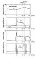
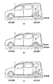
図12(a)は、車高調整によって車体1を低下させる状態を示している。図12(a)に示すように、目標車高Htよりも高い状態で車高調整装置を動作させると、コントローラ26は、排気バルブ12および給排気バルブ15を開弁させる。これにより、エアサスペンション3からエアが排出されるから、エアサスペンション3は縮小し、車体1は下降する。このとき、図10中の時刻t01~t02までの間に示すように、車高Hは減少する。これに対し、圧力Pは、低下傾向(負の値)となるものの、その変化は比較的小さくなる。
図12(b)は、車体1の下降途中でスノーバンクが発生した状態を示している。図12(b)に示すように、車体1の下降途中で車体1の下部が障害物に衝突すると、障害物によって車体1の下降が妨げられる。このとき、エアサスペンション3からエアを排出しても、車体1の下降が抑えられる。このため、図10中の時刻t02~t03までの間に示すように、障害物の衝突前に比べて、車高Hは一定値に固定され、圧力Pは大きく低下し始める。この結果、車高変化率ΔHの最大値ΔHmaxは閾値ΔHsb1よりも大きくなり、圧力変化率ΔPは閾値ΔPsb1よりも低下する。即ち、圧力変化率ΔPは、負の値で、その絶対値が大きくなる。この状態が一定時間以上に亘って継続されると、コントローラ26は、スノーバンクであると判定する。
そこで、コントローラ26は、スノーバンクを回避するために、車高調整の動作を停止し、車体1を下降動作とは逆方向(上昇方向)に向けて衝突回避量dhだけ変位させる。具体的には、コントローラ26は、排気バルブ12を開弁から閉弁に切り換えた後に、エアコンプレッサモジュール5を駆動して、エアサスペンション3に圧縮エアを供給する。これにより、図10中の時刻t03~t04までの間に示すように、圧力Pは上昇し、車高Hは増加する。この結果、図12(c)に示すように、車体1は上昇して障害物から離れるから、車両の移動が可能になる。図12(c)は、スノーバンクの検出後に、車体1を上昇させた状態を示している。
次に、車体1の上昇時に車体1の上部が障害物に衝突してガレージシーリングが発生する場合について説明する。
図13(a)は、車高調整によって車体1を上昇させる状態を示している。図13(a)に示すように、目標車高Htよりも低い状態で車高調整装置を動作させると、コントローラ26は、排気バルブ12を閉弁させ、給排気バルブ15を開弁させた状態で、エアコンプレッサモジュール5を駆動させる。これにより、圧縮エアがエアサスペンション3に供給されるから、エアサスペンション3は伸長し、車体1は上昇する。このとき、図11中の時刻t11~t12までの間に示すように、車高Hは増加する。これに対し、圧力Pは、上昇傾向(正の値)となるものの、その変化は比較的小さくなる。
図13(b)は、車体1の上昇途中でガレージシーリングが発生した状態を示している。図13(b)に示すように、車体1の上昇途中で車体1の上部が障害物に衝突すると、障害物によって車体1の上昇が妨げられる。このとき、圧縮エアをエアサスペンション3に供給しても、車体1の上昇が抑えられる。このため、図11中の時刻t12~t13までの間に示すように、障害物の衝突前に比べて、車高Hは一定値に固定され、圧力Pは大きく上昇し始める。この結果、車高変化率ΔHの最小値ΔHminは閾値ΔHgc1よりも小さくなり、圧力変化率ΔPは閾値ΔPgc1よりも増加する。この状態が一定時間以上に亘って継続されると、コントローラ26は、ガレージシーリングであると判定する。
そこで、コントローラ26は、ガレージシーリングを回避するために、車高調整の動作を停止し、車体1を上昇動作とは逆方向(下降方向)に向けて衝突回避量dhだけ変位させる。具体的には、コントローラ26は、排気バルブ12を開弁して、エアサスペンション3からエアを排出する。これにより、図11中の時刻t13~t14までの間に示すように、圧力Pは低下し、車高Hは減少する。この結果、図13(c)に示すように、車体1は下降して障害物から離れるから、車両の移動が可能になる。図13(c)は、ガレージシーリングの検出後に、車体1を下降させた状態を示している。
かくして、第1の実施の形態の車高調整装置によれば、コントローラ26は、車高センサ16および圧力センサ17により車体1の移動が制限されたと判断したとき、車高センサ16および圧力センサ17の検出値(車高H、圧力P)に基づいて、車体1の移動が制限されるよう上方または下方への車体1の移動を停止し、逆方向への移動に切換える。これにより、外部の被接触体である障害物が車体1の上方および下方のいずれの位置に配置されたときでも、車体1と物体との衝突を精度良く検出することができる。これに加えて、車体1の移動が制限されたときに、車高調整の移動方向と逆方向に移動させるから、車体1を障害物から離して、車両のダメージを抑制できると共に、車両の移動が可能な状態にすることができる。
また、SB判定で用いる閾値ΔHsb1,ΔPsb1と、GC判定で用いる閾値ΔHgc1,ΔPgc1は、圧力Pおよび車高Hに応じて変化させる構成とした。このため、エアばね4の特性およびバンプラバー特性を考慮して、SB判定およびGC判定を行うことができる。
また、コントローラ26は、図4中の禁止条件1,2に示すように、車高Hがエアサスペンション3の伸び切り車高Hfr付近または縮み切り車高Hfj付近にあるときには、SB判定およびGC判定を行わないものとした。例えばエアばね4が高圧な状態では、排気動作を行っても、車高Hが僅かしか下降しない場合がある。また、エアばね4が超低圧な状態では、給気動作を行っても、車高Hが僅かしか上昇しないことがある。このように車高Hの変化が小さいときに、障害物への衝突を判定しないから、誤判定を抑制することができる。
これに加えて、コントローラ26は、禁止条件3~5に示すように、誤判定が想定される状況では、障害物への衝突の判定を禁止する。このため、誤判定を抑制することができる。
次に、図1~図4、図14、図15は本発明の第2の実施の形態を示している。第2の実施の形態の特徴は、衝突判定に用いる車高変化率、圧力変化率の閾値を過去に計測した車高変化率、圧力変化率に基づいて算出することにある。なお、第2の実施の形態では、前述した第1の実施の形態と同一の構成要素に同一の符号を付し、その説明を省略するものとする。
第2の実施の形態によるコントローラ31は、第1の実施の形態によるコントローラ26とほぼ同様に構成される。このため、コントローラ31の記憶部31Aには、第1の実施の形態と同様に、図3に示す車高調整制御処理のプログラム等が格納されている。コントローラ31は、図3に示す車高調整制御処理を実行する。
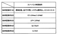
コントローラ31は、図3中のステップ6で、第1の実施の形態によるSB判定条件1(1)~5(1)およびGC判定条件1(1)~5(1)に代えて、図14に示すSB判定条件1(2)~5(2)と、図15に示すGC判定条件1(2)~5(2)とを設定する。
このとき、第2の実施の形態によるSB判定条件1(2),4(2),5(2)は、第1の実施の形態によるSB判定条件1(1),4(1),5(1)と同一である。第2の実施の形態によるGC判定条件1(2),4(2),5(2)は、第1の実施の形態によるGC判定条件1(1),4(1),5(1)と同一である。
一方、第2の実施の形態では、SB判定条件2(2),3(2)で用いる閾値ΔHsb2,ΔPsb2と、GC判定条件2(2),3(2)で用いる閾値ΔHgc2,ΔPgc2が、第1の実施の形態で用いる閾値ΔHsb1,ΔHgc1,ΔPsb1,ΔPgc1とは異なる。
具体的には、閾値ΔHsb2,ΔHgc2は、過去の車高変化量ΔHを平均化することによって、以下の数1、数2の式に基づいて算出される。なお、車高変化量ΔHの下付き符号kは、過去に遡る計測回数を示している。即ち、k=0が今回計測された車高変化量ΔHを示し、k=1が1回前に計測された車高変化量ΔHを示し、k=NがN回前に計測された車高変化量ΔHを示している。
このため、閾値ΔHsb2は、過去N回分に今回分を加えた合計(N+1)回分の車高変化量ΔHの平均値にマージンdHsbを加算した値を示している。同様に、閾値ΔHgc2は、過去N回分に今回分を加えた合計(N+1)回分の車高変化量ΔHの平均値にマージンdHgcを加算した値を示している。マージンdHsb,dHgcは、例えば実際の車両で得られる車高変化量ΔH等を考慮して、予め設定されている。

また、閾値ΔPsb2,ΔPgc2は、過去の圧力変化量ΔPを平均化することによって、以下の数3、数4の式に基づいて算出される。なお、圧力変化量ΔPの下付き符号kは、過去に遡る計測回数を示している。即ち、k=0が今回計測された圧力変化量ΔPを示し、k=1が1回前に計測された圧力変化量ΔPを示し、k=NがN回前に計測された圧力変化量ΔPを示している。
このため、閾値ΔPsb2は、過去N回分に今回分を加えた合計(N+1)回分の圧力変化量ΔPの平均値にマージンdPsbを加算した値を示している。同様に、閾値ΔPgc2は、過去N回分に今回分を加えた合計(N+1)回分の圧力変化量ΔPの平均値にマージンdPgcを加算した値を示している。マージンdPsb,dPgcは、例えば実際の車両で得られる圧力変化量ΔP等を考慮して、予め設定されている。

なお、閾値ΔHsb2,ΔHgc2,ΔPsb2,ΔPgc2の算出に用いる過去の車高変化量ΔHおよび圧力変化量ΔPの回数(N回)は、誤判定の発生状況を考慮して、適宜設定されるものである。
コントローラ31は、図3中のステップ9で、全てのSB判定条件1(2)~5(2)が一定時間に亘って成立したか否かを判定する。ステップ9で「YES」と判定したときには、ステップ10に移行する。ステップ10では、コントローラ31は、車高調整を停止するのに加え、目標車高Htを現在の車高Hに衝突回避量dh(例えばdh=10mm)を加えた値に設定する(Ht=H+dh)。
一方、ステップ9で「NO」と判定したときには、ステップ11に移行する。ステップ11では、コントローラ31は、全てのGC判定条件1(2)~5(2)が一定時間に亘って成立したか否かを判定する。ステップ11で「YES」と判定したときには、ステップ12に移行する。ステップ12では、コントローラ31は、車高調整を停止するのに加え、目標車高Htを現在の車高Hに衝突回避量dhを差し引いた値に設定する(Ht=H-dh)。ステップ11で「NO」と判定したときには、コントローラ31は、目標車高Htを、現在の値に保持する。
かくして、第2の実施の形態でも、第1の実施の形態とほぼ同様の作用効果を得ることができる。ここで、車高変化量ΔHおよび圧力変化量ΔPは、車高H、圧力P、バッテリ電圧V等のような種々の条件で変化する。このため、第1の実施の形態では、判定用の閾値ΔHsb1,ΔHgc1,ΔPsb1,ΔPgc1は、車高H、圧力P、バッテリ電圧V等のような種々の条件に基づいて、算出するものとした。
これに対し、第2の実施の形態では、SB判定およびGC判定に用いる閾値ΔHsb2,ΔHgc2,ΔPsb2,ΔPgc2が、実際に計測される車高変化量ΔHおよび圧力変化量ΔPに基づいて逐次設定される。具体的には、コントローラ31は、車高調整を開始してからの車高変化量ΔHおよび圧力変化量ΔPを記憶し、これら記憶した過去の車高変化量ΔHおよび圧力変化量ΔPに基づいて、現在の閾値ΔHsb2,ΔHgc2,ΔPsb2,ΔPgc2を決定する。このため、種々の条件を考慮する必要がなくなる。
但し、閾値ΔHsb2,ΔHgc2,ΔPsb2,ΔPgc2を決定するために、所定時間に亘って過去の車高変化量ΔHおよび圧力変化量ΔPを記憶する必要があり、車高調整の開始時には障害物への接触を検出することができない。このため、車高調整の開始時は、第1の実施の形態による閾値ΔHsb1,ΔHgc1,ΔPsb1,ΔPgc1を用い、一定時間が経過した後に、第2の実施の形態による閾値ΔHsb2,ΔHgc2,ΔPsb2,ΔPgc2に切り換えてもよい。
次に、図1~図4、図16~図17は本発明の第3の実施の形態を示している。第3の実施の形態の特徴は、圧力変化率を車高変化率で除した値に基づいて、SB判定およびGC判定を行うことにある。なお、第3の実施の形態では、前述した第1の実施の形態と同一の構成要素に同一の符号を付し、その説明を省略するものとする。
第3の実施の形態によるコントローラ41は、第1の実施の形態によるコントローラ26とほぼ同様に構成される。このため、コントローラ41の記憶部41Aには、第1の実施の形態と同様に、図3に示す車高調整制御処理のプログラム等が格納されている。コントローラ41は、図3に示す車高調整制御処理を実行する。
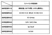
コントローラ41は、図3中のステップ6で、第1の実施の形態によるSB判定条件1(1)~5(1)およびGC判定条件1(1)~5(1)に代えて、図16に示すSB判定条件1(3)~6(3)と、図17に示すGC判定条件1(3)~6(3)とを設定する。
SB判定条件1(3)は、停車状態で、全ドアが閉じて、システムに異常がないことである。SB判定条件2(3)は、検出された車高Hがエアサスペンション3の伸び切り車高Hfrの90%よりも高い(H>Hfr×0.9)こと、または、検出された車高Hがエアサスペンション3の縮み切り車高Hfjの90%よりも低い(H<Hfj×0.9)ことである。SB判定条件3(3)は、車高変化率ΔHの最大値ΔHmaxが、負の値である(0>ΔHmax)ことである。SB判定条件4(3)は、圧力変化率ΔPを車高変化率ΔHで除した値(ΔP/ΔH)が車高Hと圧力Pとに基づいて決められた閾値Rsbよりも大きい(Rsb<ΔP/ΔH)ことである。SB判定条件5(3)は、給排気バルブ15の電流指令Ipv(電流値)が予め決められた駆動電流値Ipv0(例えばIpv0=0.2A)よりも大きい(Ipv>Ipv0)ことである。SB判定条件6(3)は、排気バルブ12の電流指令Iv(電流値)が予め決められた駆動電流値Iv0(例えばIv0=0.4A)よりも大きい(Iv>Iv0)ことである。
GC判定条件1(3)は、停車状態で、全ドアが閉じて、システムに異常がないことである。GC判定条件2(3)は、検出された車高Hがエアサスペンション3の伸び切り車高Hfrの90%よりも高い(H>Hfr×0.9)こと、または、検出された車高Hがエアサスペンション3の縮み切り車高Hfjの90%よりも低い(H>Hfj×0.9)ことである。GC判定条件3(3)は、車高変化率ΔHの最小値ΔHminが、正の値である(0<ΔHmin)ことである。GC判定条件4(3)は、圧力変化率ΔPを車高変化率ΔHで除した値(ΔP/ΔH)が車高Hと圧力Pとに基づいて決められた閾値Rgcよりも大きい(Rgc<ΔP/ΔH)ことである。GC判定条件5(3)は、空気圧縮機6の駆動指令がON(出力状態)になっていることである。GC判定条件6(3)は、給排気バルブ15の電流指令Ipv(電流値)が予め決められた駆動電流値Ipv0(例えばIpv0=0.2A)よりも大きい(Ipv>Ipv0)ことである。
ここで、コントローラ41の記憶部41Aには、閾値Rsb,Rgcのマップが格納されている。このため、コントローラ41は、現在の車高Hと圧力Pとに基づいて、閾値Rsb,Rgcを算出する。このとき、閾値Rsb,Rgcは、同じ値でもよく、異なる値でもよい。なお、閾値Rsb,Rgcは、実測した車高変化量ΔHおよび圧力変化量ΔPに基づいて逐次設定してもよい。この場合には、SB判定やGC判定の精度を向上させることができる。
コントローラ41は、図3中のステップ9で、全てのSB判定条件1(3)~6(3)が一定時間に亘って成立したか否かを判定する。ステップ9で「YES」と判定したときには、ステップ10に移行する。ステップ10では、コントローラ41は、車高調整を停止するのに加え、目標車高Htを現在の車高Hに衝突回避量dh(例えばdh=10mm)を加えた値に設定する(Ht=H+dh)。
一方、ステップ9で「NO」と判定したときには、ステップ11に移行する。ステップ11では、コントローラ41は、全てのGC判定条件1(3)~6(3)が一定時間に亘って成立したか否かを判定する。ステップ11で「YES」と判定したときには、ステップ12に移行する。ステップ12では、コントローラ41は、車高調整を停止するのに加え、目標車高Htを現在の車高Hに衝突回避量dhを差し引いた値に設定する(Ht=H-dh)。ステップ11で「NO」と判定したときには、コントローラ41は、目標車高Htを、現在の値に保持する。
かくして、第3の実施の形態でも、第1の実施の形態とほぼ同様の作用効果を得ることができる。第3の実施の形態では、コントローラ41は、圧力センサ17が検出した検出値(圧力P)による圧力変化率ΔPを、車高センサ16が検出した検出値(車高H)による車高変化率ΔHで除した値により、車体1の上方または下方への移動が制限されたことを判定する。このため、例えば空気圧縮機6の性能に依存しなくなるため、車高調整装置のロバスト性を向上させることができる。
なお、第3の実施の形態では、SB判定条件5(3)は、給排気バルブ15の電流指令Ipvが予め決められた駆動電流値Ipv0よりも大きい(Ipv>Ipv0)こととした。本発明はこれに限らず、例えばSB判定条件5(3)に代えて、給排気バルブ15の電流指令Ipvが駆動電流値Ipv0よりも大きい(Ipv>Ipv0)状態が所定時間に亘って継続したことをSB判定条件の1つにしてもよい。このとき、所定時間は、実車で車高変化しない最大時間(例えば7秒)にマージン分(例えば3秒)を加えた値(例えば10秒)に設定される。この理由は、エアサスペンション3のこじりやヒステリシス特性によって、車高調整開始後に実際の車高が変化しない場合がある点を考慮したものである。このように障害物との衝突に依らずに車高Hが一時的に変化しない場合でも、所定時間の継続を条件に加えることによって、誤判定を抑制することができる。
この場合、図3中のステップ9では、全てのSB判定条件が一定時間に亘って成立したか否かを判定する。このとき、一定時間は、スノーバンクおよびガレージシーリングの両方とも判定されていない状態では、短時間(例えば2秒間)に設定される。一方、前回の検出でガレージシーリングが判定された後は、一定時間は、障害物への衝突から検出までの最大時間(例えば12秒)にマージン(例えば1秒)を追加した時間から、初期判定時間である所定時間(例えば10秒)を差し引いた値(例えば3秒間)に設定される。このようなSB判定は、第1,第2の実施の形態にも適用することができる。
また、第3の実施の形態では、GC判定条件5(3)は、給排気バルブ15の電流指令Ipvが予め決められた駆動電流値Ipv0よりも大きい(Ipv>Ipv0)こととした。本発明はこれに限らず、例えばGC判定条件5(3)に代えて、給排気バルブ15の電流指令Ipvが駆動電流値Ipv0よりも大きい(Ipv>Ipv0)状態が所定時間に亘って継続したことをSB判定条件の1つにしてもよい。このとき、所定時間は、実車で車高変化しない最大時間(例えば7秒)にマージン分(例えば3秒)を加えた値(例えば10秒)設定される。
この場合、図3中のステップ11では、全てのGC判定条件が一定時間に亘って成立したか否かを判定する。このとき、一定時間は、スノーバンクおよびガレージシーリングの両方とも判定されていない状態では、短時間(例えば2秒間)に設定される。一方、前回の検出でスノーバンクが判定された後は、一定時間は、SG判定条件と同様に初期判定時間である所定時間を考慮した時間(例えば3秒間)に設定される。このようなGC判定は、第1,第2の実施の形態にも適用することができる。
また、第3の実施の形態では、衝突判定禁止条件として、スノーバンクを検出した後にガレージシーリングを検出した場合と、ガレージシーリングを検出した後にスノーバンクを検出した場合を、追加してもよい。この理由は、スノーバンクとガレージシーリングとが反復して判定されるのを防止するためである。このような衝突判定の禁止は、第1,第2の実施の形態にも適用することができる。
前記各実施の形態では、図3中のステップ6,7が衝突判定禁止手段の具体例を示し、ステップ8,9,11が衝突判定手段の具体例を示している。また、前記各実施の形態では、障害物との衝突判定と、エアサスペンション3の制御とを同一のコントローラ26,31,41が実行するものとした。本発明はこれに限らず、障害物との衝突判定と、エアサスペンションの制御とを別個のコントローラが実行してもよい。即ち、別個のコントローラによる判定結果に基づいて、コントローラ26,31,41がエアサスペンション3を制御してもよい。
前記各実施の形態では、エアサスペンション3は、後輪2C,2Dに設ける構成とした。本発明はこれに限らず、全ての車輪2A~2Dにエアサスペンションを設けてもよく、前輪のみにエアサスペンションを設けてもよい。
前記各実施の形態では、エアコンプレッサモジュール5と、流体圧力装置としてのエアサスペンション3とを備えた空圧式のサスペンション装置を例に挙げて説明した。本発明はこれに限らず、例えば油圧ポンプと、流体圧力装置としての油圧ダンパや油圧シリンダとを備えた油圧式のサスペンション装置に適用してもよい。
また、本発明は、磁力によって車高の調整が可能な電磁サスペンションに適用してもよい。この場合、車体の上方または下方への移動の制限に関する物理量として、例えば電磁サスペンションに供給する電流を検出してもよい。即ち、検出装置は、電磁サスペンションに供給する電流を検出する電流センサによって構成してもよい。
前記各実施の形態では、エアサスペンション装置を4輪自動車の車両に適用した場合を例に挙げて説明した。本発明はこれに限らず、例えば鉄道車両等のような他の車両に適用してもよい。
次に、上記の実施の形態に含まれる諸形態について記載する。車両の複数の車輪のうち少なくとも、一対の前輪または一対の後輪に設けられ、前記車輪と車体との間の距離である車高を調整する車高調整アクチュエータと、前記車高調整アクチュエータを、前記車高が目標車高に近づくように制御するアクチュエータ制御装置と、前記車体が外部の被接触体との接触により上方または下方への移動が制限されたときに変化する物理量を検出する検出装置と、を備え、前記アクチュエータ制御装置は、前記検出装置により前記車体の移動が制限されたと判断されたときに、前記検出装置の検出値に基づいて、上方または下方への前記車体の移動を停止し、逆方向への移動に切換える構成とした。
これにより、被接触体となる障害物が車体の上方および下方のいずれの位置に配置されたときでも、車体と物体との衝突を精度良く検出することができる。これに加えて、車体の移動が制限されたときに、車高調整の移動方向と逆方向に移動させるから、車体を障害物から離して、車両のダメージを抑制できると共に、車両の移動が可能な状態にすることができる。
前記車高調整アクチュエータは、流体圧力により前記車高を調整する流体圧力装置であり、前記検出装置は、車高検出装置と、前記流体圧力装置に作用する流体圧力を検出する圧力検出装置と、を備え、前記アクチュエータ制御装置は、前記圧力検出装置が検出した検出値から算出される圧力変化率と、前記車高検出装置が検出した検出値から算出される車高変化率とに基づいて、前記車体の上方または下方への移動が制限されたか否かを判定する構成とした。このとき、車体が障害物に衝突した否かに応じて、車高変化率と圧力変化率との関係が変化する。このため、車高変化率と圧力変化率との関係に基づいて、車体と障害物との衝突を検出することができる。
前記アクチュエータ制御装置は、前記圧力検出装置が検出した検出値と前記車高検出装置が検出した検出値とに基づいて算出した前記圧力変化率の閾値と、前記圧力検出装置が検出した検出値と前記車高検出装置が検出した検出値とに基づいて算出した前記車高変化率の閾値と、を用いて、前記車体の上方または下方への移動が制限されたか否かを判定する構成とした。このため、流体圧力装置の特性等を考慮することができる。
前記アクチュエータ制御装置は、過去に検出した前記圧力変化率から算出した前記圧力変化率についての閾値と、過去に検出した前記車高変化率から算出した前記車高変化率についての閾値と、を用いて、前記車体の上方または下方への移動が制限されたか否かを判定する構成とした。このとき、圧力変化率および車高変化率は、圧力、車高等のような種々の条件に基づいて変化する。これに対し、過去に検出した値から圧力変化率および車高変化率の閾値を算出するから、種々の条件を考慮する必要がなくなる。
前記車高調整アクチュエータは、流体圧力により前記車高を調整する流体圧力装置であり、前記検出装置は、車高検出装置と、前記流体圧力装置に作用する流体圧力を検出する圧力検出装置と、を備え、前記アクチュエータ制御装置は、前記圧力検出装置が検出した検出値から算出される圧力変化率を、前記車高検出装置が検出した検出値から算出される車高変化率で除した値に基づいて、前記車体の上方または下方への移動が制限されたか否かを判定する構成とした。このため、例えば流体圧力の供給源の性能に依存しなくなるため、車高調整装置のロバスト性を向上させることができる。
前記圧力変化率を前記車高変化率で除した値についての判定閾値を、実測した車高変化量および圧力変化量に基づいて逐次設定する構成とした。これにより、障害物との接触の判定精度を高めることができる。
以上、本発明のいくつかの実施形態について説明してきたが、上述した発明の実施形態は、本発明の理解を容易にするためのものであり、本発明を限定するものではない。本発明は、その趣旨を逸脱することなく、変更、改良され得るとともに、本発明にはその均等物が含まれる。また、上述した課題の少なくとも一部を解決できる範囲、または、効果の少なくとも一部を奏する範囲において、特許請求の範囲および明細書に記載された各構成要素の任意の組み合わせ、または、省略が可能である。
本願は、2016年3月29日出願の日本特許出願番号2016-065467号に基づく優先権を主張する。2016年3月29日出願の日本特許出願番号2016-065467号の明細書、特許請求の範囲、図面及び要約書を含む全ての開示内容は、参照により全体として本願に組み込まれる。
1 車体、 2A~2D 車輪、 3 エアサスペンション(流体圧力装置)、 5 エアコンプレッサモジュール、 12 排気バルブ(排気弁)、 15 給排気バルブ(給排気弁)、 16 車高センサ(車高検出装置)、 17 圧力センサ(圧力検出装置)、 21 バッテリ、 26,31,41 コントローラ(アクチュエータ制御装置)
Claims (6)
- 車高調整装置であって、
車両の複数の車輪のうち少なくとも、一対の前輪または一対の後輪に設けられ、前記車輪と車体との間の距離である車高を調整する車高調整アクチュエータと、
前記車高調整アクチュエータを、前記車高が目標車高に近づくように制御するアクチュエータ制御装置と、
前記車体が外部の被接触体との接触により上方または下方への移動が制限されたときに変化する物理量を検出する検出装置と、
を備え、
前記アクチュエータ制御装置は、前記検出装置により前記車体の移動が制限されたと判断されたときに、前記検出装置の検出値に基づいて、上方または下方への前記車体の移動を停止し、逆方向への移動に切換える
車高調整装置。 - 請求項1に記載の車高調整装置であって、
前記車高調整アクチュエータは、流体圧力により前記車高を調整する流体圧力装置であり、
前記検出装置は、車高検出装置と、前記流体圧力装置に作用する流体圧力を検出する圧力検出装置と、を備え、
前記アクチュエータ制御装置は、前記圧力検出装置が検出した検出値から算出される圧力変化率と、前記車高検出装置が検出した検出値から算出される車高変化率とに基づいて、前記車体の上方または下方への移動が制限されたか否かを判定する
車高調整装置。 - 請求項2に記載の車高調整装置であって、
前記アクチュエータ制御装置は、前記圧力検出装置が検出した検出値と前記車高検出装置が検出した検出値とに基づいて算出した前記圧力変化率の閾値と、前記圧力検出装置が検出した検出値と前記車高検出装置が検出した検出値とに基づいて算出した前記車高変化率の閾値と、を用いて、前記車体の上方または下方への移動が制限されたか否かを判定する
車高調整装置。 - 請求項2に記載の車高調整装置であって、
前記アクチュエータ制御装置は、過去に検出した前記圧力変化率から算出した前記圧力変化率についての閾値と、過去に検出した前記車高変化率から算出した前記車高変化率についての閾値と、を用いて、前記車体の上方または下方への移動が制限されたか否かを判定する
車高調整装置。 - 請求項1に記載の車高調整装置であって、
前記車高調整アクチュエータは、流体圧力により前記車高を調整する流体圧力装置であり、
前記検出装置は、車高検出装置と、前記流体圧力装置に作用する流体圧力を検出する圧力検出装置と、を備え、
前記アクチュエータ制御装置は、前記圧力検出装置が検出した検出値から算出される圧力変化率を、前記車高検出装置が検出した検出値から算出される車高変化率で除した値に基づいて、前記車体の上方または下方への移動が制限されたか否かを判定する
車高調整装置。 - 請求項5に記載の車高調整装置であって、
前記圧力変化率を前記車高変化率で除した値についての判定閾値を、実測した車高変化量および圧力変化量に基づいて逐次設定する
車高調整装置。
Priority Applications (5)
| Application Number | Priority Date | Filing Date | Title |
|---|---|---|---|
| JP2018509259A JP6646732B2 (ja) | 2016-03-29 | 2017-03-24 | 車高調整装置 |
| KR1020187027323A KR102117777B1 (ko) | 2016-03-29 | 2017-03-24 | 차고 조정 장치 |
| DE112017001745.9T DE112017001745B4 (de) | 2016-03-29 | 2017-03-24 | Fahrzeughöhenjustiervorrichtung |
| CN201780020440.5A CN109070679B (zh) | 2016-03-29 | 2017-03-24 | 车高调整装置 |
| US16/087,335 US11052719B2 (en) | 2016-03-29 | 2017-03-24 | Vehicle height adjustment device |
Applications Claiming Priority (2)
| Application Number | Priority Date | Filing Date | Title |
|---|---|---|---|
| JP2016-065467 | 2016-03-29 | ||
| JP2016065467 | 2016-03-29 |
Publications (1)
| Publication Number | Publication Date |
|---|---|
| WO2017170253A1 true WO2017170253A1 (ja) | 2017-10-05 |
Family
ID=59965585
Family Applications (1)
| Application Number | Title | Priority Date | Filing Date |
|---|---|---|---|
| PCT/JP2017/012101 Ceased WO2017170253A1 (ja) | 2016-03-29 | 2017-03-24 | 車高調整装置 |
Country Status (6)
| Country | Link |
|---|---|
| US (1) | US11052719B2 (ja) |
| JP (1) | JP6646732B2 (ja) |
| KR (1) | KR102117777B1 (ja) |
| CN (1) | CN109070679B (ja) |
| DE (1) | DE112017001745B4 (ja) |
| WO (1) | WO2017170253A1 (ja) |
Cited By (5)
| Publication number | Priority date | Publication date | Assignee | Title |
|---|---|---|---|---|
| WO2020084963A1 (ja) * | 2018-10-25 | 2020-04-30 | 日立オートモティブシステムズ株式会社 | サスペンションシステム |
| JP2021098436A (ja) * | 2019-12-20 | 2021-07-01 | 日立Astemo株式会社 | 車高調整装置 |
| JP2022080902A (ja) * | 2020-11-19 | 2022-05-31 | 東日本旅客鉄道株式会社 | 鉄道車両における蓄圧系の異常検知方法 |
| JP2023502273A (ja) * | 2019-11-21 | 2023-01-23 | テスラ,インコーポレイテッド | 調整可能な車両用サスペンション |
| CN117007338A (zh) * | 2023-07-27 | 2023-11-07 | 一汽解放青岛汽车有限公司 | 标定高度调整支架以及方法 |
Families Citing this family (7)
| Publication number | Priority date | Publication date | Assignee | Title |
|---|---|---|---|---|
| JP6807975B2 (ja) * | 2019-04-12 | 2021-01-06 | 本田技研工業株式会社 | 電動サスペンション装置 |
| CN115635815B (zh) * | 2021-07-20 | 2025-03-11 | 本田技研工业株式会社 | 车高调整装置 |
| CN116852931B (zh) * | 2022-03-28 | 2026-07-14 | 比亚迪股份有限公司 | 一种主动悬架控制方法、装置、电子设备及可读存储介质 |
| CN117382604A (zh) * | 2022-07-04 | 2024-01-12 | 北京罗克维尔斯科技有限公司 | 虚拟快艇航行状态的模拟方法及其装置 |
| CN117087374A (zh) * | 2022-07-11 | 2023-11-21 | 北京罗克维尔斯科技有限公司 | 车辆的运动控制方法、装置、车载系统及车辆 |
| CN118596942B (zh) * | 2024-06-25 | 2025-01-14 | 比亚迪股份有限公司 | 电池包的加热控制方法、系统、电子设备、车辆和介质 |
| US12552218B1 (en) * | 2025-04-10 | 2026-02-17 | GM Global Technology Operations LLC | Air spring suspension system with variable flow valves |
Citations (4)
| Publication number | Priority date | Publication date | Assignee | Title |
|---|---|---|---|---|
| JPH04108023A (ja) * | 1990-08-29 | 1992-04-09 | Nissan Motor Co Ltd | 電子制御流体圧サスペンション |
| JPH08503184A (ja) * | 1992-11-07 | 1996-04-09 | エア・ログ リミテッド | 乗車高さ変更可能な車両の懸架システム |
| JP2007099096A (ja) * | 2005-10-05 | 2007-04-19 | Toyota Motor Corp | 車両制御装置 |
| JP2008018787A (ja) * | 2006-07-11 | 2008-01-31 | Toyota Motor Corp | 車高制御装置 |
Family Cites Families (19)
| Publication number | Priority date | Publication date | Assignee | Title |
|---|---|---|---|---|
| JPS6064282A (ja) * | 1983-09-19 | 1985-04-12 | Nissan Motor Co Ltd | 超音波式距離測定装置 |
| JP2531825Y2 (ja) * | 1988-04-28 | 1997-04-09 | 株式会社 ユニシアジェックス | 車高調整装置 |
| JPH051513U (ja) * | 1991-06-28 | 1993-01-14 | 株式会社アツギユニシア | 車高調整装置 |
| JPH065467A (ja) | 1992-06-24 | 1994-01-14 | Nec Corp | 電気二重層コンデンサ |
| DE19729274A1 (de) | 1997-07-09 | 1999-01-14 | Wabco Gmbh | Verfahren zum Ändern der Höhenlage wenigstens eines Bereiches eines Fahrzeugaufbaues |
| JP3470573B2 (ja) * | 1997-11-21 | 2003-11-25 | トヨタ自動車株式会社 | 車高調整装置 |
| JP3428414B2 (ja) * | 1998-01-12 | 2003-07-22 | トヨタ自動車株式会社 | 車両の車高調整装置 |
| JP3646499B2 (ja) * | 1998-01-16 | 2005-05-11 | トヨタ自動車株式会社 | 車高調整装置 |
| DE19959012C5 (de) | 1999-12-08 | 2008-09-11 | Continental Aktiengesellschaft | Verfahren zur Steuerung bzw. Regelung des Niveaus eines Fahrzeugaufbaus eines Kraftfahrzeuges |
| JP4135146B2 (ja) * | 2003-06-05 | 2008-08-20 | いすゞ自動車株式会社 | 車高調整装置 |
| KR100599487B1 (ko) * | 2004-09-06 | 2006-07-12 | 현대모비스 주식회사 | 폐루프 차고조절시스템 |
| JP4506463B2 (ja) * | 2004-12-28 | 2010-07-21 | トヨタ自動車株式会社 | 車高調整装置 |
| JP4539694B2 (ja) * | 2007-08-28 | 2010-09-08 | トヨタ自動車株式会社 | 車高調整装置 |
| JP2016065467A (ja) | 2014-09-24 | 2016-04-28 | スズキ株式会社 | エンジンの始動制御装置 |
| JP2016175573A (ja) * | 2015-03-20 | 2016-10-06 | アイシン精機株式会社 | 車高調整装置 |
| DE112016002980B4 (de) * | 2015-06-30 | 2021-12-16 | Hitachi Automotive Systems, Ltd. | Federungssystem |
| JP2017217933A (ja) * | 2016-06-03 | 2017-12-14 | アイシン精機株式会社 | 車高調整装置 |
| US10926602B2 (en) * | 2016-09-28 | 2021-02-23 | Hitachi Automotive Systems, Ltd. | Suspension control apparatus |
| JP6579125B2 (ja) * | 2017-02-15 | 2019-09-25 | トヨタ自動車株式会社 | サスペンションシステム |
-
2017
- 2017-03-24 CN CN201780020440.5A patent/CN109070679B/zh active Active
- 2017-03-24 WO PCT/JP2017/012101 patent/WO2017170253A1/ja not_active Ceased
- 2017-03-24 DE DE112017001745.9T patent/DE112017001745B4/de active Active
- 2017-03-24 JP JP2018509259A patent/JP6646732B2/ja active Active
- 2017-03-24 US US16/087,335 patent/US11052719B2/en active Active
- 2017-03-24 KR KR1020187027323A patent/KR102117777B1/ko active Active
Patent Citations (4)
| Publication number | Priority date | Publication date | Assignee | Title |
|---|---|---|---|---|
| JPH04108023A (ja) * | 1990-08-29 | 1992-04-09 | Nissan Motor Co Ltd | 電子制御流体圧サスペンション |
| JPH08503184A (ja) * | 1992-11-07 | 1996-04-09 | エア・ログ リミテッド | 乗車高さ変更可能な車両の懸架システム |
| JP2007099096A (ja) * | 2005-10-05 | 2007-04-19 | Toyota Motor Corp | 車両制御装置 |
| JP2008018787A (ja) * | 2006-07-11 | 2008-01-31 | Toyota Motor Corp | 車高制御装置 |
Cited By (12)
| Publication number | Priority date | Publication date | Assignee | Title |
|---|---|---|---|---|
| WO2020084963A1 (ja) * | 2018-10-25 | 2020-04-30 | 日立オートモティブシステムズ株式会社 | サスペンションシステム |
| JPWO2020084963A1 (ja) * | 2018-10-25 | 2021-09-02 | 日立Astemo株式会社 | サスペンションシステム |
| JP7133639B2 (ja) | 2018-10-25 | 2022-09-08 | 日立Astemo株式会社 | サスペンションシステム |
| JP2023502273A (ja) * | 2019-11-21 | 2023-01-23 | テスラ,インコーポレイテッド | 調整可能な車両用サスペンション |
| US12151673B2 (en) | 2019-11-21 | 2024-11-26 | Tesla, Inc. | Adjustable suspension for a vehicle |
| JP7730813B2 (ja) | 2019-11-21 | 2025-08-28 | テスラ,インコーポレイテッド | 調整可能な車両用サスペンション |
| JP2025128258A (ja) * | 2019-11-21 | 2025-09-02 | テスラ,インコーポレイテッド | 調整可能な車両用サスペンション |
| JP2021098436A (ja) * | 2019-12-20 | 2021-07-01 | 日立Astemo株式会社 | 車高調整装置 |
| JP7213172B2 (ja) | 2019-12-20 | 2023-01-26 | 日立Astemo株式会社 | 車高調整装置 |
| JP2022080902A (ja) * | 2020-11-19 | 2022-05-31 | 東日本旅客鉄道株式会社 | 鉄道車両における蓄圧系の異常検知方法 |
| JP7467318B2 (ja) | 2020-11-19 | 2024-04-15 | 東日本旅客鉄道株式会社 | 鉄道車両における蓄圧系の異常検知方法 |
| CN117007338A (zh) * | 2023-07-27 | 2023-11-07 | 一汽解放青岛汽车有限公司 | 标定高度调整支架以及方法 |
Also Published As
| Publication number | Publication date |
|---|---|
| US11052719B2 (en) | 2021-07-06 |
| JP6646732B2 (ja) | 2020-02-14 |
| US20200298645A1 (en) | 2020-09-24 |
| DE112017001745B4 (de) | 2021-12-16 |
| JPWO2017170253A1 (ja) | 2018-12-20 |
| CN109070679A (zh) | 2018-12-21 |
| KR20180114189A (ko) | 2018-10-17 |
| KR102117777B1 (ko) | 2020-06-01 |
| CN109070679B (zh) | 2021-12-03 |
| DE112017001745T5 (de) | 2018-12-13 |
Similar Documents
| Publication | Publication Date | Title |
|---|---|---|
| JP6646732B2 (ja) | 車高調整装置 | |
| JP6539346B2 (ja) | サスペンション装置 | |
| CN104039570B (zh) | 机动车的空气悬架系统和用于对其进行控制的方法 | |
| CN106414121B (zh) | 用于对空气悬挂式机动车辆进行水平调节的方法 | |
| US9783018B2 (en) | Vehicle height adjustment apparatus | |
| US9168806B2 (en) | Vehicle height adjustment apparatus | |
| US9394965B2 (en) | Absorber system for vehicle | |
| US20190176562A1 (en) | Vehicle-height control system | |
| JPH11198627A (ja) | 車高調整装置 | |
| CN115139719A (zh) | 悬架系统以及能够调整车高的车辆 | |
| JP5250349B2 (ja) | 制動力制御装置 | |
| KR101365123B1 (ko) | 자동차 차체의 레벨을 제어 및/또는 조절하기 위한 방법 | |
| JP7133639B2 (ja) | サスペンションシステム | |
| JP2020066291A (ja) | サスペンションシステム | |
| JP6187199B2 (ja) | 車高調整装置 | |
| JP2004316809A (ja) | 流体作動機器の制御装置 | |
| KR20170075600A (ko) | 차량용 능동형 현가장치 | |
| WO2020066515A1 (ja) | エアサスペンション装置 | |
| JP2018086861A (ja) | エアサスペンション装置 | |
| Ha et al. | Height sensor fault diagnosis for electronic air suspension (EAS) system | |
| JP6367130B2 (ja) | 車高調整装置 | |
| JP4797869B2 (ja) | 車両用サスペンションシステム | |
| JP2007099096A (ja) | 車両制御装置 | |
| JPS63199109A (ja) | 車高制御装置 | |
| JPH0415122B2 (ja) |
Legal Events
| Date | Code | Title | Description |
|---|---|---|---|
| WWE | Wipo information: entry into national phase |
Ref document number: 2018509259 Country of ref document: JP |
|
| WWE | Wipo information: entry into national phase |
Ref document number: 1020187027323 Country of ref document: KR |
|
| 121 | Ep: the epo has been informed by wipo that ep was designated in this application |
Ref document number: 17774790 Country of ref document: EP Kind code of ref document: A1 |
|
| 122 | Ep: pct application non-entry in european phase |
Ref document number: 17774790 Country of ref document: EP Kind code of ref document: A1 |