US11052719B2 - Vehicle height adjustment device - Google Patents
Vehicle height adjustment device Download PDFInfo
- Publication number
- US11052719B2 US11052719B2 US16/087,335 US201716087335A US11052719B2 US 11052719 B2 US11052719 B2 US 11052719B2 US 201716087335 A US201716087335 A US 201716087335A US 11052719 B2 US11052719 B2 US 11052719B2
- Authority
- US
- United States
- Prior art keywords
- vehicle height
- vehicle
- pressure
- variation rate
- detection device
- Prior art date
- Legal status (The legal status is an assumption and is not a legal conclusion. Google has not performed a legal analysis and makes no representation as to the accuracy of the status listed.)
- Active, expires
Links
Images


Classifications
-
- B—PERFORMING OPERATIONS; TRANSPORTING
- B60—VEHICLES IN GENERAL
- B60G—VEHICLE SUSPENSION ARRANGEMENTS
- B60G17/00—Resilient suspensions having means for adjusting the spring or vibration-damper characteristics, for regulating the distance between a supporting surface and a sprung part of vehicle or for locking suspension during use to meet varying vehicular or surface conditions, e.g. due to speed or load
- B60G17/015—Resilient suspensions having means for adjusting the spring or vibration-damper characteristics, for regulating the distance between a supporting surface and a sprung part of vehicle or for locking suspension during use to meet varying vehicular or surface conditions, e.g. due to speed or load the regulating means comprising electric or electronic elements
- B60G17/018—Resilient suspensions having means for adjusting the spring or vibration-damper characteristics, for regulating the distance between a supporting surface and a sprung part of vehicle or for locking suspension during use to meet varying vehicular or surface conditions, e.g. due to speed or load the regulating means comprising electric or electronic elements characterised by the use of a specific signal treatment or control method
-
- B—PERFORMING OPERATIONS; TRANSPORTING
- B60—VEHICLES IN GENERAL
- B60G—VEHICLE SUSPENSION ARRANGEMENTS
- B60G17/00—Resilient suspensions having means for adjusting the spring or vibration-damper characteristics, for regulating the distance between a supporting surface and a sprung part of vehicle or for locking suspension during use to meet varying vehicular or surface conditions, e.g. due to speed or load
- B60G17/015—Resilient suspensions having means for adjusting the spring or vibration-damper characteristics, for regulating the distance between a supporting surface and a sprung part of vehicle or for locking suspension during use to meet varying vehicular or surface conditions, e.g. due to speed or load the regulating means comprising electric or electronic elements
- B60G17/016—Resilient suspensions having means for adjusting the spring or vibration-damper characteristics, for regulating the distance between a supporting surface and a sprung part of vehicle or for locking suspension during use to meet varying vehicular or surface conditions, e.g. due to speed or load the regulating means comprising electric or electronic elements characterised by their responsiveness, when the vehicle is travelling, to specific motion, a specific condition, or driver input
-
- B—PERFORMING OPERATIONS; TRANSPORTING
- B60—VEHICLES IN GENERAL
- B60G—VEHICLE SUSPENSION ARRANGEMENTS
- B60G17/00—Resilient suspensions having means for adjusting the spring or vibration-damper characteristics, for regulating the distance between a supporting surface and a sprung part of vehicle or for locking suspension during use to meet varying vehicular or surface conditions, e.g. due to speed or load
- B60G17/015—Resilient suspensions having means for adjusting the spring or vibration-damper characteristics, for regulating the distance between a supporting surface and a sprung part of vehicle or for locking suspension during use to meet varying vehicular or surface conditions, e.g. due to speed or load the regulating means comprising electric or electronic elements
- B60G17/019—Resilient suspensions having means for adjusting the spring or vibration-damper characteristics, for regulating the distance between a supporting surface and a sprung part of vehicle or for locking suspension during use to meet varying vehicular or surface conditions, e.g. due to speed or load the regulating means comprising electric or electronic elements characterised by the type of sensor or the arrangement thereof
-
- B—PERFORMING OPERATIONS; TRANSPORTING
- B60—VEHICLES IN GENERAL
- B60G—VEHICLE SUSPENSION ARRANGEMENTS
- B60G2202/00—Indexing codes relating to the type of spring, damper or actuator
- B60G2202/40—Type of actuator
- B60G2202/41—Fluid actuator
- B60G2202/413—Hydraulic actuator
-
- B—PERFORMING OPERATIONS; TRANSPORTING
- B60—VEHICLES IN GENERAL
- B60G—VEHICLE SUSPENSION ARRANGEMENTS
- B60G2300/00—Indexing codes relating to the type of vehicle
- B60G2300/12—Cycles; Motorcycles
-
- B—PERFORMING OPERATIONS; TRANSPORTING
- B60—VEHICLES IN GENERAL
- B60G—VEHICLE SUSPENSION ARRANGEMENTS
- B60G2400/00—Indexing codes relating to detected, measured or calculated conditions or factors
- B60G2400/20—Speed
- B60G2400/204—Vehicle speed
-
- B—PERFORMING OPERATIONS; TRANSPORTING
- B60—VEHICLES IN GENERAL
- B60G—VEHICLE SUSPENSION ARRANGEMENTS
- B60G2400/00—Indexing codes relating to detected, measured or calculated conditions or factors
- B60G2400/25—Stroke; Height; Displacement
- B60G2400/252—Stroke; Height; Displacement vertical
-
- B—PERFORMING OPERATIONS; TRANSPORTING
- B60—VEHICLES IN GENERAL
- B60G—VEHICLE SUSPENSION ARRANGEMENTS
- B60G2400/00—Indexing codes relating to detected, measured or calculated conditions or factors
- B60G2400/50—Pressure
- B60G2400/51—Pressure in suspension unit
-
- B—PERFORMING OPERATIONS; TRANSPORTING
- B60—VEHICLES IN GENERAL
- B60G—VEHICLE SUSPENSION ARRANGEMENTS
- B60G2400/00—Indexing codes relating to detected, measured or calculated conditions or factors
- B60G2400/80—Exterior conditions
- B60G2400/82—Ground surface
- B60G2400/823—Obstacle sensing
-
- B—PERFORMING OPERATIONS; TRANSPORTING
- B60—VEHICLES IN GENERAL
- B60G—VEHICLE SUSPENSION ARRANGEMENTS
- B60G2500/00—Indexing codes relating to the regulated action or device
- B60G2500/30—Height or ground clearance
-
- B—PERFORMING OPERATIONS; TRANSPORTING
- B60—VEHICLES IN GENERAL
- B60G—VEHICLE SUSPENSION ARRANGEMENTS
- B60G2600/00—Indexing codes relating to particular elements, systems or processes used on suspension systems or suspension control systems
- B60G2600/02—Retarders, delaying means, dead zones, threshold values, cut-off frequency, timer interruption
-
- B—PERFORMING OPERATIONS; TRANSPORTING
- B60—VEHICLES IN GENERAL
- B60G—VEHICLE SUSPENSION ARRANGEMENTS
- B60G2800/00—Indexing codes relating to the type of movement or to the condition of the vehicle and to the end result to be achieved by the control action
- B60G2800/90—System Controller type
- B60G2800/91—Suspension Control
- B60G2800/914—Height Control System
-
- B—PERFORMING OPERATIONS; TRANSPORTING
- B62—LAND VEHICLES FOR TRAVELLING OTHERWISE THAN ON RAILS
- B62K—CYCLES; CYCLE FRAMES; CYCLE STEERING DEVICES; RIDER-OPERATED TERMINAL CONTROLS SPECIALLY ADAPTED FOR CYCLES; CYCLE AXLE SUSPENSIONS; CYCLE SIDE-CARS, FORECARS, OR THE LIKE
- B62K25/00—Axle suspensions
- B62K25/04—Axle suspensions for mounting axles resiliently on cycle frame or fork
- B62K2025/044—Suspensions with automatic adjustment
Definitions
- the present invention relates to a vehicle height adjustment device preferably mounted on a vehicle such as a four-wheeled vehicle, for example.
- PTL 1 discloses a vehicle height adjustment device which cancels a vehicle height adjustment when the presence of an object is detected within a set region of a vehicle before the vehicle height adjustment is started or during the adjustment.
- a surrounding object detection device formed of a clearance sonar, a millimeter wave radar or the like, is provided at each of four corners of a vehicle, and the presence of an object is detected using these surrounding object detection devices. Accordingly, for example, when an obstacle comes directly beneath the vehicle, the object may not be detected.
- the bottom of the vehicle body impacts with the object so that wheels tend to lift up.
- drive wheels lift up there is a possibility that the vehicle cannot acquire a drive force thus being prevented from staring moving.
- the surrounding object detection device described in PTL 1 performs a detection of an object disposed in front of or below the vehicle, but does not perform a detection of an object disposed above the vehicle. Accordingly, for example, there is a problem that when the vehicle height is increased in a state where a vehicle enters a garage having a low ceiling, an upper portion of the vehicle body impacts with the ceiling of the garage.
- a vehicle height adjustment device includes: vehicle height adjustment actuators which are provided to at least a pair of front wheels or a pair of rear wheels out of a plurality of wheels of a vehicle, and which are configured to adjust a vehicle height defined by a distance between the wheels and a vehicle body; an actuator control device configured to control the vehicle height adjustment actuators such that the vehicle height approximates to a target vehicle height; and a detection device configured to detect a physical quantity which varies as upward or downward movement of the vehicle body is restricted due to contact with an external contacted object, wherein with the determination by the detection device that the movement of the vehicle body is restricted, the actuator control device stops the upward or downward movement of the vehicle body, and switches to movement in an opposite direction based on a detected value of the detection device.
- an impact between a vehicle body and an object can be detected with high accuracy.
- FIG. 1 is a conceptual view showing a vehicle on which a vehicle height adjustment device according to a first, second or third embodiment of the present invention is mounted.
- FIG. 2 is a circuit configuration diagram showing the vehicle height adjustment device in FIG. 1 .
- FIG. 3 is a flow chart showing vehicle height adjustment control processing performed by a controller in FIG. 2 .
- FIG. 4 is an explanatory view showing one example of impact determination prohibition conditions.
- FIG. 5 is an explanatory view showing one example of snow bank determination conditions according to the first embodiment.
- FIG. 6 is an explanatory view showing one example of garage ceiling determination conditions according to the first embodiment.
- FIG. 7 is an explanatory view showing one example of a relationship of a vehicle height with respect to a vehicle height variation rate and a pressure variation rate.
- FIG. 8 is an explanatory view showing one example of a relationship of a pressure with respect to the vehicle height variation rate and the pressure variation rate.
- FIG. 9 is an explanatory view showing one example of a relationship of a battery voltage with respect to the vehicle height variation rate and the pressure variation rate.
- FIG. 10 is a characteristic diagram showing one example of temporal variations in vehicle height, vehicle height variation rate, pressure, and pressure variation rate when snow bank occurs in the process of lowering a vehicle body.
- FIG. 11 is a characteristic diagram showing one example of temporal variations in vehicle height, vehicle height variation rate, pressure, and pressure variation rate when garage ceiling occurs in the process of elevating the vehicle body.
- FIG. 12 is an explanatory view showing a state of a vehicle when snow bank occurs in the process of lowering the vehicle body.
- FIG. 13 is an explanatory view showing a state of the vehicle when garage ceiling occurs in the process of elevating the vehicle body.
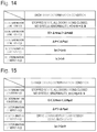
- FIG. 14 is an explanatory view showing one example of snow bank determination conditions according to the second embodiment.
- FIG. 15 is an explanatory view showing one example of garage ceiling determination conditions according to the second embodiment.
- FIG. 16 is an explanatory view showing one example of snow bank determination conditions according to the third embodiment.
- FIG. 17 is an explanatory view showing one example of garage ceiling determination conditions according to the third embodiment.
- vehicle height adjustment devices according to embodiments of the present invention are described in detail with reference to attached drawings by taking, as an example, a case where the vehicle height adjustment device is mounted on a vehicle such as a four-wheeled vehicle.
- FIG. 1 to FIG. 6 show the first embodiment of the present invention.
- a vehicle body 1 forming a body of the vehicle.
- left front and right front wheels 2 A, 2 B front wheels
- left rear and right rear wheels 2 C, 2 D rear wheels
- Air suspensions 3 form a fluid pressure device which adjusts a vehicle height H by a fluid pressure (air pressure).
- the air suspensions 3 are respectively provided to two wheels 2 C, 2 D (rear wheels) positioned on the rear side out of four wheels 2 A to 2 D of the vehicle.
- two air suspensions 3 are provided so as to respectively correspond to the two wheels 2 C, 2 D such that each air suspension 3 is interposed between the vehicle body 1 of the vehicle and the wheel 2 C, 2 D.
- Each air suspension 3 includes an air spring 4 .
- the air suspensions 3 form a vehicle height adjustment actuator. Accordingly, the air suspensions 3 adjust the vehicle height H defined by a distance between the wheel 2 C, 2 D and the vehicle body 1 with the supply or discharge of air, serving as a working fluid, to or from the air suspensions 3 .
- the air springs 4 When compressed air is supplied or discharged through branch pipe passages 14 A, 14 B and intake and exhaust valves 15 , the air springs 4 are extended or contracted in the vertical direction corresponding to the amount of supply or discharge (amount of air) at this point. With such operations, the air suspensions 3 individually perform a vehicle height adjustment for the vehicle body 1 so that a vehicle height H is increased or decreased individually for each wheel 2 C, 2 D.
- An air compressor module 5 includes an air compressor 6 and an electric motor 7 , and forms a hydraulic/pneumatic pump which is operated with the supply of power from a battery 21 .
- the air compressor module 5 is mounted on a rear portion side of the vehicle body 1 , for example, and supplies compressed air to the air springs 4 of the air suspensions 3 .
- the air compressor 6 is formed of a reciprocating compressor, a scroll compressor, or other compressor, for example.
- Check valves 6 A are respectively provided to the suction side and the discharge side of the air compressor 6 .
- the air compressor 6 is driven by the electric motor 7 serving as a drive source.
- the air compressor 6 compresses outside air or atmosphere which the compressor 6 sucks from the suction filter 8 side, thus generating compressed air (air).
- a suction filter 8 also functions as a silencer which reduces suction noises.
- An intake and exhaust pipe passage 9 is provided to be connected to the discharge side of the air compressor 6 . As shown in FIG. 2 , one side (proximal end side) of the intake and exhaust pipe passage 9 is connected to the discharge side of the air compressor 6 , and the other side (distal end side) of the intake and exhaust pipe passage 9 extends to the outside of the air compressor module 5 .
- the branch pipe passages 14 A, 14 B are connected to the distal end side of the intake and exhaust pipe passage 9 .
- An air dryer 10 is interposed at an intermediate portion of the intake and exhaust pipe passage 9 , and dries air.
- the air dryer 10 incorporates a moisture absorbent (not shown in the drawing) or the like, for example, and is disposed between a slow return valve 11 and an exhaust pipe passage 13 .
- the slow return valve 11 has a parallel circuit formed of a throttle 11 A and a check valve 1113 .
- the check valve 1113 is opened with respect to a flow in a forward direction from the air compressor 6 toward the air suspensions 3 , and a flow rate of compressed air is not reduced.
- the check valve 1113 is closed with respect to a flow in the reverse direction. At this point of operation, a flow rate of compressed air is reduced by the throttle 11 A and hence, the compressed air slowly flows backward in the air dryer 10 at a small flow rate.
- the air dryer 10 When compressed air generated by the air compressor 6 flows through the air dryer 10 in the forward direction toward the air suspension 3 side, the air dryer 10 causes this compressed air to come into contact with the moisture absorbent disposed in the inside of the air dryer 10 thus absorbing moisture so that the air dryer 10 supplies the dried compressed air toward the air springs 4 .
- compressed air (exhaust gas) discharged from the air springs 4 flows through the inside of the air dryer 10 in the reverse direction, the dried air flows backward through the inside of the air dryer 10 .
- moisture of the moisture absorbent in the air dryer 10 is desorbed by the dried air. With such a mechanism, the moisture absorbent is regenerated, thus being returned to a state of being able to absorb moisture again.
- An exhaust valve 12 discharges air (working fluid) on the discharge side of the air compressor module 5 (air compressor 6 ).
- the exhaust valve 12 is connected to the intake and exhaust pipe passage 9 through the exhaust pipe passage 13 .
- the exhaust valve 12 includes a solenoid (coil) 12 A, and is formed of a two-poll, two-position electromagnetic switching valve (normally closed valve of a spring offset type), for example.
- the exhaust valve 12 is normally closed, thus blocking the exhaust pipe passage 13 .
- the solenoid 12 A of the exhaust valve 12 is excited by the energization from a controller 26 , the exhaust valve 12 is opened, thus allowing the communication of the exhaust pipe passage 13 . With such operations, the exhaust valve 12 discharges (releases) compressed air in the intake and exhaust pipe passage 9 into the atmosphere.
- Two branch pipe passages 14 A, 14 B are branched from the intake and exhaust pipe passage 9 corresponding to the wheels 2 C, 2 D, and extend toward the air suspensions 3 of the wheels 2 C, 2 D. These two branch pipe passages 14 A, 14 B connect the air compressor module 5 and the air springs 4 of the air suspensions 3 to each other.
- the branch pipe passages 14 A, 14 B are branched from a distal end portion of the intake and exhaust pipe passage 9 so as to connect the air springs 4 to the intake and exhaust pipe passage 9 .
- Intake and exhaust valves 15 are respectively provided between the air compressor module 5 and the air suspensions 3 .
- each intake and exhaust valve 15 is positioned between the air compressor 6 of the air compressor module 5 and the air spring 4 of the air suspension 3 , is provided to the two branch pipe passages 14 A, 14 B.
- the intake and exhaust valve 15 has the same configuration as the exhaust valve 12 . That is, the intake and exhaust valve 15 includes a solenoid 15 A, and is formed of a two-port, two-position electromagnetic switching valve, for example.
- the intake and exhaust valve 15 is formed as a normally closed valve of a spring offset type. In this embodiment, the description is made with respect to the configuration which uses the intake and exhaust valve 15 where an intake valve and an exhaust valve are integrally formed. However, the intake valve and the exhaust valve may be provided separately.
- the solenoid 15 A is electrically connected to the controller 26 .
- the intake and exhaust valve 15 sucks (moves) a plunger (not shown in the drawing) against a force of the spring, thus being opened.
- compressed air can be supplied to or discharged from the air suspensions 3 .
- the intake and exhaust valve 15 is closed by the force of the spring. In such a valve closed state, the intake and exhaust valve 15 can stop supply or discharge of compressed air to or from the air suspensions 3 .
- a vehicle height sensor 16 is provided to each air suspension 3 .
- the vehicle height sensor 16 forms a part of a detection device which detects physical quantities varying when upward or downward movement of the vehicle body 1 is restricted due to contact with an external contacted object. That is, the vehicle height sensor 16 is a vehicle height detection device, and detects a vehicle height H (vehicle height value) of the air suspension 3 based on a length dimension (a dimension in the upward or downward direction) of the air spring 4 in a direction in which the air spring 4 is extended or contracted.
- the vehicle height sensor 16 outputs a detection signal of the vehicle height H to the controller 26 .
- a pressure sensor 17 is also provided to the intake and exhaust pipe passage 9 at a position between the slow return valve 11 and the intake and exhaust valves 15 .
- the pressure sensor 17 forms a part of the detection device which detects the physical quantities varying when the upward or downward movement of the vehicle body 1 is restricted due to contact with an external contacted object. That is, the pressure sensor 17 is a pressure detection device which detects an air pressure acting on the air suspensions 3 . Accordingly, the pressure sensor 17 detects a pressure P (pressure value) of compressed air (air) on the discharge side of the air compressor module 5 (air compressor 6 ). To be more specific, the pressure sensor 17 detects the pressure P of the compressed air supplied to the air springs 4 . The pressure sensor 17 outputs a detection signal of the pressure P to the controller 26 .
- the battery 21 is provided to the vehicle.
- a positive terminal of the electric motor 7 is connected to the battery 21 , serving as a power source, through a compressor relay 23 and a fuse 24 .
- a voltage sensor 22 which detects a battery voltage V, is connected to the battery 21 .
- the voltage sensor 22 detects the battery voltage V, and outputs a detection signal of the battery voltage V to the controller 26 .
- a negative terminal of the electric motor 7 is connected to the ground.
- Choke coils 7 A for suppressing an inrush current or the like are respectively connected to the positive terminal and the negative terminal of the electric motor 7 .
- a thermal relay 25 between the choke coil 7 A and the battery 21 is also connected to the positive terminal of the electric motor 7 .
- the controller 26 forms an actuator control device which controls the air suspensions 3 such that the vehicle height H approximates to a target vehicle height Ht.
- the controller 26 controls driving and stopping of the air compressor module 5 including the air compressor 6 and the electric motor 7 .
- the controller 26 controls opening and closing of the exhaust valve 12 and the intake and exhaust valves 15 .
- the input side of the controller 26 is connected to the vehicle height sensor 16 , to the pressure sensor 17 , and to the voltage sensor 22 .
- the output side of the controller 26 is connected to the coil 23 A of the compressor relay 23 , to the solenoid 12 A of the exhaust valve 12 , and to the solenoids 15 A of the intake and exhaust valves 15 .
- the controller 26 includes a memory section 26 A formed of a ROM, a RAM, a nonvolatile memory and the like, for example.
- the memory section 26 A stores, for example, a program and the like for vehicle height adjustment control processing shown in FIG. 3 .
- the controller 26 controls the air suspensions 3 , thus adjusting a vehicle height H of the vehicle.
- the controller 26 controls an electric current to be supplied to the electric motor 7 and, controls an electric current to be supplied to the solenoid 12 A of the exhaust valve 12 and the solenoids 15 A of the intake and exhaust valves 15 .
- the vehicle height adjustment control processing performed by the controller 26 is described with reference to FIG. 1 to FIG. 9 .
- the vehicle height adjustment control processing shown in FIG. 3 is actuated at the start of a vehicle height adjustment, for example, and is repeatedly performed at a predetermined time interval.
- GC determination a garage ceiling determination
- step 1 the controller 26 reads in a vehicle height H and a pressure P with detection signals from the vehicle height sensor 16 and the pressure sensor 17 .
- the controller 26 also reads in a battery voltage V with a detection signal from the voltage sensor 22 .
- the controller 26 calculates a vehicle height variation rate ⁇ H as a variation rate of vehicle height H per unit time.
- the controller 26 calculates a pressure variation rate ⁇ P as a variation rate of pressure P per unit time.
- step 2 it is determined whether or not the SB determination or the GC determination is in progress.
- the vehicle height adjustment control processing is in progress, and thus the processing proceeds to step 3 .
- step 3 a condition for cancelling an impact determination (SB determination or GC determination) with respect to an obstacle is calculated.
- SB determination or GC determination a condition for cancelling an impact determination with respect to an obstacle is calculated.
- a vehicle speed 5 km/h, for example
- a condition for determining an OFF state of a power source is set.
- the value of a vehicle speed for determining whether or not the vehicle is in a traveling state is not limited to the exemplified value, and is set appropriately.
- step 4 it is determined whether or not the cancellation condition set in step 3 is established.
- the controller 26 determines whether or not the vehicle is in a traveling state, or whether or not the power source is in an OFF state.
- step 4 when it is determined “NO” in step 4 , the cancellation condition is not established. To be more specific, the vehicle is in a stopped state, and the power source is in an ON state. Accordingly, the processing proceeds to step 6 where an impact determination prohibition conditions are calculated.
- the prohibition condition 1 is that the vehicle height H, which is detected by the vehicle height sensor 16 , is higher than 90% of a fully extended vehicle height Hfr at which the air suspensions 3 are fully extended (H>Hfr ⁇ 0.9).
- the prohibition condition 2 is that the vehicle height H is lower than 90% of a fully contracted vehicle height Hfj at which the air suspensions 3 are fully contracted (H ⁇ Hfj ⁇ 0.9).
- the prohibition condition 3 is that a system has no abnormality.
- the prohibition condition 4 is that a door of the vehicle is open.
- the prohibition condition 5 is that a vehicle is in a traveling state.
- a value for determining whether or not the vehicle height H is in the vicinity of the fully extended vehicle height Hfr is not limited to 90% of the fully extended vehicle height Hfr.
- a value for determining whether or not the vehicle height H is in the vicinity of the fully contracted vehicle height Hfj is not limited to 90% of the fully contracted vehicle height Hfj.
- Each of these values is a margin with respect to the vehicle height Hfr, Hfj, and is appropriately set within a range of 75% to 95%, for example, based on a situation where an erroneous determination occurs.
- step 7 it is determined whether or not the impact determination is prohibited.
- the controller 26 determines whether or not at least one of the prohibition conditions 1 to 5 , which are set in step 6 , is satisfied.
- step 7 When it is determined “YES” in step 7 , any one of the prohibition conditions 1 to 5 is satisfied and hence, the controller 26 maintains the target vehicle height Ht at the current value, and the processing proceeds to step 13 .
- step 7 when it is determined “NO” in step 7 , none of the prohibition conditions 1 to 5 is satisfied and hence, the vehicle is in a state where the impact determination can be performed. Accordingly, the processing proceeds to step 8 where thresholds ⁇ Hsb1, ⁇ Hgc1, ⁇ Psb1, ⁇ Pgc1, which are used for the SB determination and the GC determination, are calculated.
- Relationships shown in FIG. 7 to FIG. 9 are established between a current vehicle height H, a current pressure P, a current battery voltage V, a vehicle height variation rate ⁇ H, and a pressure variation rate ⁇ P, for example.
- the vehicle height H when the vehicle height H is increased to a high position, the vehicle height H approximates to the vehicle height at which the air suspensions 3 are fully extended and hence, the vehicle height variation rate ⁇ H becomes small, while the pressure variation rate ⁇ P becomes large.
- the vehicle height H is in the vicinity of zero (initial value)
- the vehicle height H is between the vehicle height at which the air suspensions 3 are fully extended and the vehicle height at which the air suspensions 3 are fully contracted. Accordingly, in both a case where the vehicle height H is increased and a case where the vehicle height H is decreased, the vehicle height variation rate ⁇ H becomes large, while the pressure variation rate ⁇ P becomes small.
- FIG. 7 shows one example of the relationship between the vehicle height H and the variation rates ⁇ H, ⁇ P.
- both the vehicle height variation rate ⁇ H and the pressure variation rate ⁇ P become small.
- both the vehicle height variation rate ⁇ H and the pressure variation rate ⁇ P become large.
- both the vehicle height variation rate ⁇ H and the pressure variation rate ⁇ P become large.
- both the pressure P is low at the time of decreasing the vehicle height H, both the vehicle height variation rate ⁇ H and the pressure variation rate ⁇ P become small.
- the relationship between the pressure P and the variation rates ⁇ H, ⁇ P vary according to characteristics of the air springs 4 . Accordingly, FIG. 8 shows one example of the relationship between the pressure P and the variation rates ⁇ H, ⁇ P.
- Thresholds ⁇ Hsb1, ⁇ Hgc1 of the vehicle height variation rate ⁇ H and thresholds ⁇ Psb1, ⁇ Pgc1 of the pressure variation rate ⁇ P are calculated based on the current vehicle height H, the current pressure P, and the current battery voltage V by taking into account the characteristics shown in FIG. 7 to FIG. 9 .
- the threshold ⁇ Hgc1 of the vehicle height variation rate ⁇ H and the threshold ⁇ Pgc1 of the pressure variation rate ⁇ P are calculated based on the current vehicle height H, the current pressure P, and the current battery voltage V.
- the threshold ⁇ Hsb1 of the vehicle height variation rate ⁇ H and the threshold ⁇ Psb1 of the pressure variation rate ⁇ P which are used for the SB determination, are calculated based on the current vehicle height H and the current pressure P.
- Snow bank occurs when the vehicle height H is decreased.
- the air compressor module 5 is not driven, and compressed air is discharged to the atmosphere by opening the exhaust valve 12 . Accordingly, in calculating the thresholds ⁇ Hsb1, ⁇ Psb1, which are used for the SB determination, it is unnecessary to take into account a battery voltage V.
- An air pressure circuit is a closed circuit. Accordingly, for driving the air compressor module 5 also in decreasing the vehicle height H, it is necessary to take into account a battery voltage V also in calculating the thresholds ⁇ Hsb1, ⁇ Psb1, which are used for the SB determination.
- step 8 impact determination conditions are calculated in addition to the thresholds ⁇ Hsb1, ⁇ Hgc1, ⁇ Psb1, ⁇ Pgc1.
- the SB determination conditions 1 ( 1 ) to 5 ( 1 ) shown in FIG. 5 and the GC determination conditions 1 ( 1 ) to 5 ( 1 ) shown in FIG. 6 are set.
- the SB determination condition 1 ( 1 ) is that the vehicle is in a stopped state, all doors are closed, a system has no abnormality, and the detected vehicle height H is higher than 90% of the fully extended vehicle height Hfr at which the air suspensions 3 are fully extended (H>Hfr ⁇ 0.9).
- the SB determination condition 2 ( 1 ) is that a maximum value ⁇ Hmax of the vehicle height variation rate ⁇ H is a negative value, and is larger than the threshold ⁇ Hsb1 (0> ⁇ Hmax> ⁇ Hsb1).
- the SB determination condition 3 ( 1 ) is that the pressure variation rate ⁇ P is smaller than the threshold ⁇ Psb1 ( ⁇ P ⁇ Psb1).
- the GC determination condition 1 ( 1 ) is that the vehicle is in a stopped state, all doors are closed, a system has no abnormality, and the detected vehicle height H is lower than 90% of the fully contracted vehicle height Hfj at which the air suspensions 3 are fully contracted (H ⁇ Hfj ⁇ 0.9).
- the GC determination condition 2 ( 1 ) is that a minimum value ⁇ Hmin of the vehicle height variation rate ⁇ H is a positive value, and is smaller than the threshold ⁇ Hgc1 (0 ⁇ Hmin ⁇ Hge1).
- the GC determination condition 3 ( 1 ) is that a pressure variation rate ⁇ P is larger than the threshold ⁇ Pgc1 ( ⁇ P> ⁇ Pgc1).
- the GC determination condition 4 ( 1 ) is that a drive command for the air compressor 6 is in an ON state (in an output state).
- the maximum value ⁇ Hmax and the minimum value ⁇ Hmin of the vehicle height variation rate ⁇ H show the maximum value and the minimum value of the vehicle height variation rate ⁇ H which are calculated in the present control period.
- Specific numerical values of the drive current values Ipv0, Iv0 are merely for the sake of example, and are appropriately set for respective actual vehicles.
- step 9 it is determined whether or not all SB determination conditions 1 ( 1 ) to 5 ( 1 ) are established over a specific time.
- the specific time is set to a short time (2 seconds, for example) in a state where neither the snow bank (SB) nor the garage ceiling (GC) is determined. After the garage ceiling is determined in the previous detection, the specific time is set to a long time (10 seconds, for example).
- step 11 it is determined whether or not all GC determination conditions 1 ( 1 ) to 5 ( 1 ) are established over a specific time.
- the specific time is set to a short time (2 seconds, for example) in a state where neither the snow bank nor the garage ceiling is determined.
- the specific time is set to a long time (10 seconds, for example).
- the specific time is not limited to an exemplified numerical value, and is appropriately set by taking into account a situation where an erroneous determination occurs.
- step 11 when it is determined “NO” in step 11 , it is considered that neither the snow bank nor the garage ceiling is occurring. Accordingly, the processing proceeds to step 13 in a state where the target vehicle height Ht is maintained at a current value.
- step 13 the controller 26 performs the vehicle height adjustment so as to assume the target vehicle height Ht. That is, when the target vehicle height Ht is higher than the current vehicle height H, the controller 26 causes the vehicle body 1 to be elevated. On the other hand, when the target vehicle height Ht is lower than the current vehicle height H, the controller 26 causes the vehicle body 1 to be lowered. When the target vehicle height Ht is a value close to the current vehicle height H, the controller 26 stops an elevating or lowering operation for the vehicle body 1 so as to maintain the current vehicle height H.
- FIG. 12( a ) shows a state where the vehicle body 1 is lowered by performing the vehicle height adjustment.
- the controller 26 opens the exhaust valve 12 and the intake and exhaust valves 15 . With such operations, air is discharged from the air suspensions 3 and hence, the air suspensions 3 contract so that the vehicle body 1 is lowered.
- the vehicle height H decreases as shown in FIG. 10 between time t 01 to t 02 . With such a decrease, although the pressure P tends to decrease (assumes a negative value), a variation in the pressure P is relatively small.
- FIG. 12( b ) shows a state where the snow bank occurs in the process of lowering the vehicle body 1 .
- FIG. 12( b ) when the lower portion of the vehicle body 1 impacts with the obstacle in the process of lowering the vehicle body 1 , the lowering of the vehicle body 1 is obstructed by the obstacle. At this point of operation, if air is discharged from the air suspensions 3 , lowering of the vehicle body 1 is prevented. Accordingly, as shown in FIG. 10 between time t 02 to t 03 , compared to values before the vehicle impacts with the obstacle, the vehicle height H is fixed at a specific value, and the pressure P starts to drop significantly.
- the controller 26 determines that the snow bank is occurring.
- the controller 26 stops the operation of the vehicle height adjustment, and causes the vehicle body 1 to displace toward a direction (elevating direction) opposite to the direction in the lowering operation by the impact avoidance amount dh.
- the controller 26 drives the air compressor module 5 so as to supply compressed air to the air suspensions 3 .
- the pressure P increases and the vehicle height H increases as shown in FIG. 10 between time t 03 to t 04 .
- FIG. 12( e ) shows a state where the vehicle body 1 is elevated after the snow bank is detected.
- FIG. 13( a ) shows a state where the vehicle body 1 is elevated by performing the vehicle height adjustment.
- the controller 26 drives the air compressor module 5 while the exhaust valve 12 is closed and the intake and exhaust valves 15 are opened. With such operations, compressed air is supplied to the air suspensions 3 and hence, the air suspensions 3 extend so that the vehicle body 1 is elevated.
- the vehicle height H increases as shown in FIG. 11 between time t 11 to t 12 . With such an increase, although the pressure P tends to increase (assumes a positive value), a variation in the pressure P is relatively small.
- FIG. 13( b ) shows a state where the garage ceiling occurs in the process of elevating the vehicle body 1 .
- FIG. 13( b ) when the upper portion of the vehicle body 1 impacts with the obstacle in the process of elevating the vehicle body 1 , the elevating of the vehicle body 1 is obstructed by the obstacle. At this point of operation, if compressed air is supplied to the air suspensions 3 , elevating of the vehicle body 1 is prevented. Accordingly, as shown in FIG. 11 between time 112 to t 13 , compared to values before the vehicle impacts with the obstacle, the vehicle height H is fixed at a specific value, and the pressure P starts to increase significantly.
- the controller 26 determines that the garage ceiling is occurring.
- the controller 26 stops the operation of the vehicle height adjustment, and causes the vehicle body 1 to displace toward a direction (lowering direction) opposite to the direction in the elevating operation by the impact avoidance amount dh.
- the controller 26 opens the exhaust valve 12 so as to discharge air from the air suspensions 3 .
- the pressure P decreases and the vehicle height H decreases as shown in FIG. 11 between time t 13 to t 14 .
- FIG. 13( c ) shows a state where the vehicle body 1 is lowered after the garage ceiling is detected.
- the controller 26 stops the upward or downward movement of the vehicle body 1 so as to restrict the movement of the vehicle body 1 , and switches the movement of the vehicle body 1 to the movement in the opposite direction.
- the thresholds ⁇ Hsb1, ⁇ Psb1, which are used for the SB determination, and the thresholds ⁇ Hgc1, ⁇ Pgc1, which are used for the GC determination vary corresponding to the pressure P and the vehicle height H. Accordingly, the SB determination and the GC determination can be performed by taking into account characteristics of the air springs 4 and characteristics of bump rubber.
- the controller 26 does not perform the SB determination and the GC determination.
- the vehicle height H may only slightly decrease even if a discharging operation is performed.
- the vehicle height H may only slightly increase even if air supplying operation is performed. An impact with the obstacle is not determined when the variation in vehicle height H is small as described above and hence, erroneous determinations can be suppressed.
- the controller 26 is prohibited from determining an impact with an obstacle. Accordingly, erroneous determinations can be suppressed.
- FIG. 1 to FIG. 4 , FIG. 14 , and FIG. 15 show a second embodiment of the present invention.
- the second embodiment is characterized in that thresholds of a vehicle height variation rate and a pressure variation rate, which are used for an impact determination, are calculated based on past measurements of vehicle height variation rates and pressure variation rates.
- constitutional elements equal to the corresponding constitutional elements in the above-mentioned first embodiment are given the same reference numerals, and the description of such constitutional elements is omitted.
- a controller 31 according to the second embodiment is configured generally equal to the controller 26 according to the first embodiment. Accordingly, in the same manner as the first embodiment, a memory section 31 A of the controller 31 stores a program and the like for vehicle height adjustment control processing shown in FIG. 3 . The controller 31 performs the vehicle height adjustment control processing shown in FIG. 3 .
- step 6 in FIG. 3 the controller 31 sets SB determination conditions 1 ( 2 ) to 5 ( 2 ) shown in FIG. 14 and GC determination conditions 1 ( 2 ) to 5 ( 2 ) shown in FIG. 15 in place of the SB determination conditions 1 ( 1 ) to 5 ( 1 ) and the GC determination conditions 1 ( 1 ) to 5 ( 1 ) according to the first embodiment.
- the SB determination conditions 1 ( 2 ), 4 ( 2 ), 5 ( 2 ) according to the second embodiment are equal to the SB determination conditions 1 ( 1 ), 4 ( 1 ), 5 ( 1 ) according to the first embodiment.
- the GC determination conditions 1 ( 2 ), 4 ( 2 ), 5 ( 2 ) according to the second embodiment are equal to the GC determination conditions 1 ( 1 ), 4 ( 1 ), 5 ( 1 ) according to the first embodiment.
- thresholds ⁇ Hsb2, ⁇ Psb2, which are used in the SB determination conditions 2 ( 2 ), 3 ( 2 ), and thresholds ⁇ Hgc2, ⁇ Pgc2, which are used in the GC determination conditions 2 ( 2 ), 3 ( 2 ), differ from the thresholds ⁇ Hsb1, ⁇ Hgc1, ⁇ Psb1, ⁇ Pgc1 which are used in the first embodiment.
- the thresholds ⁇ Hsb2, ⁇ Hgc2 are calculated based on the following Formula 1 and Formula 2 by averaging past vehicle height variation amounts ⁇ H.
- the threshold ⁇ Hsb2 denotes a value obtained by adding a margin dHsb to the average value of vehicle height variation amounts ⁇ H for (N+1) cycles total, where the vehicle height variation amount in the present cycle is added to the vehicle height variation amounts in the previous N cycles.
- the threshold ⁇ Hgc2 denotes a value obtained by adding a margin dHgc to the average value of vehicle height variation amounts ⁇ H for (N+1) cycles total, where the vehicle height variation amount in the present cycle is added to the vehicle height variation amounts in the previous N cycles.
- the margins dHsb, dHgc are set in advance by taking into account a vehicle height variation amount ⁇ H and the like which are obtained from an actual vehicle, for example.
- the thresholds ⁇ Psb2, ⁇ Pgc2 are calculated based on the following Formula 3 and Formula 4 by averaging past pressure variation amounts ⁇ P.
- the threshold ⁇ Psb2 denotes a value obtained by adding a margin dPsb to the average value of the pressure variation amounts ⁇ P for (N+1) cycles total, where the pressure variation amount in the present cycle is added to the pressure variation amounts in the previous N cycles.
- the threshold ⁇ Pgc2 denotes a value obtained by adding a margin dPgc to the average value of the pressure variation amounts ⁇ P for (N+1) cycles total, where the pressure variation amount in the present cycle is added to the pressure variation amounts in the previous N cycles.
- the margins dPsb, dPgc are set in advance by taking into account a pressure variation amount ⁇ P and the like which are obtained from an actual vehicle, for example.
- the past vehicle height variation amounts ⁇ H and the number of cycles (N cycles) of the pressure variation amount ⁇ P which are used for calculating the thresholds ⁇ Hsb2, ⁇ Hgc2, ⁇ Psb2, ⁇ Pgc2, are appropriately set by taking into account a situation where an erroneous determination occurs.
- step 9 in FIG. 3 the controller 31 determines whether or not all SB determination conditions 1 ( 2 ) to 5 ( 2 ) are established over a specific time. When it is determined “YES” in step 9 , the processing proceeds to step 10 .
- step 11 the controller 31 determines whether or not all GC determination conditions 1 ( 2 ) to 5 ( 2 ) are established over a specific time. When it is determined “YES” in step 11 , the processing proceeds to step 12 .
- the vehicle height variation amount ⁇ H and the pressure variation amount ⁇ P vary according to various conditions such as the vehicle height H, the pressure P, or the battery voltage V. Accordingly, in the first embodiment, the thresholds ⁇ Hsb1, ⁇ Hgc1, ⁇ Psb1, ⁇ Pgc1 for the determination are calculated based on various conditions such as the vehicle height H, the pressure P, or the battery voltage V.
- the thresholds ⁇ Hsb2, ⁇ Hgc2, ⁇ Psb2, ⁇ Pgc2 used for the SB determination and the GC determination are successively set based on the vehicle height variation amount ⁇ H and the pressure variation amount ⁇ P which are actually measured.
- the controller 31 stores the vehicle height variation amount ⁇ H and the pressure variation amount ⁇ P after starting the vehicle height adjustment, and decides current thresholds ⁇ Hsb2, ⁇ Hgc2, ⁇ Psb2, ⁇ Pgc2 based on the past vehicle height variation amount ⁇ H and the past pressure variation amount W which are stored. Accordingly, it becomes unnecessary to take into account the various conditions.
- the thresholds ⁇ Hsb1, ⁇ Hgc1, ⁇ Psb1, ⁇ Pgc1 according to the first embodiment are used at the time of starting the vehicle height adjustment and, after a predetermined time elapses, the thresholds ⁇ Hsb1, ⁇ Hgc1, ⁇ Psb1, ⁇ Pgc1 are switched to the thresholds ⁇ Hsb2, ⁇ Hgc2, ⁇ Psb2, ⁇ Pgc2 according to the second embodiment.
- FIG. 1 to FIG. 4 , FIG. 16 and FIG. 17 show a third embodiment of the present invention.
- the third embodiment is characterized in that the SB determination and the GC determination are performed based on a value obtained by dividing a pressure variation rate by a vehicle height variation rate.
- constitutional elements equal to the corresponding constitutional elements in the above-mentioned first embodiment are given the same reference numerals, and the description of such constitutional elements is omitted.
- step 6 in FIG. 3 the controller 41 sets SB determination conditions 1 ( 3 ) to 6 ( 3 ) shown in FIG. 16 and GC determination conditions 1 ( 3 ) to 6 ( 3 ) shown in FIG. 17 in place of the SB determination conditions 1 ( 1 ) to 5 ( 1 ) and the GC determination conditions 1 ( 1 ) to 5 ( 1 ) according to the first embodiment.
- the SB determination condition 1 ( 3 ) is that the vehicle is in a stopped state, all doors are closed, and a system has no abnormality.
- the SB determination condition 2 ( 3 ) is that the detected vehicle height H is higher than 90% of the fully extended vehicle height Hfr at which the air suspensions 3 are fully extended (H>Hfr ⁇ 0.9), or that the detected vehicle height H is lower than 90% of the fully contracted vehicle height Hfj at which the air suspensions 3 are fully contracted (H ⁇ Hfj ⁇ 0.9).
- the SB determination condition 3 ( 3 ) is that a maximum value ⁇ Hmax of a vehicle height variation rate ⁇ H is a negative value (0> ⁇ Hmax).
- the SB determination condition 4 ( 3 ) is that a value obtained by dividing a pressure variation rate ⁇ P by a vehicle height variation rate ⁇ H ( ⁇ P/ ⁇ H) is larger than a threshold Rsb which is determined based on a vehicle height H and a pressure P (Rsb ⁇ P/ ⁇ H).
- the GC determination condition 1 ( 3 ) is that the vehicle is in a stopped state, all doors are closed, and a system has no abnormality.
- the GC determination condition 2 ( 3 ) is that the detected vehicle height H is higher than 90% of the fully extended vehicle height Hfr at which the air suspensions 3 are fully extended (H>Hfr ⁇ 0.9), or that the detected vehicle height H is lower than 90% of the fully contracted vehicle height HI) at which the air suspensions 3 are fully contracted (H>Hfj ⁇ 0.9).
- the GC determination condition 3 ( 3 ) is that a minimum value ⁇ Hmin of the vehicle height variation rate ⁇ H is a positive value (0 ⁇ Hmin).
- the GC determination condition 4 ( 3 ) is that a value obtained by dividing a pressure variation rate ⁇ P by a vehicle height variation rate ⁇ H ( ⁇ P/ ⁇ H) is larger than a threshold Rgc which is determined based on the vehicle height H and the pressure P (Rgc ⁇ P/ ⁇ H).
- the GC determination condition 5 ( 3 ) is that a drive command for the air compressor 6 is in an ON state (in an output state).
- the memory section 41 A of the controller 41 stores maps of the thresholds Rsb, Rgc. Accordingly, the controller 41 calculates the thresholds Rsb, Rgc based on a current vehicle height H and a current pressure P. At this point of operation, the thresholds Rsb, Rgc may be the same value, or may be different values. The thresholds Rsb, Rgc may be successively set based on the vehicle height variation amount ⁇ H and the pressure variation amount ⁇ P which are actually measured. In this case, accuracy in SB determination and GC determination can be enhanced.
- step 9 in FIG. 3 the controller 41 determines whether or not all SB determination conditions 1 ( 3 ) to 6 ( 3 ) are established over a specific time. When it is determined “YES” in step 9 , the processing proceeds to step 10 .
- step 11 the controller 41 determines whether or not all GC determination conditions 1 ( 3 ) to 6 ( 3 ) are established over a specific time. When it is determined “YES” in step 11 , the processing proceeds to step 12 .
- the SB determination condition 5 ( 3 ) is that the current command Ipv for the intake and exhaust valves 15 is larger than a predetermined drive current value Ipv0 (Ipv>Ipv0).
- the present invention is not limited to such a condition.
- a continuation of a state, where the current command Ipv for the intake and exhaust valves 15 is larger than the drive current value Ipv0 (Ipv>Ipv0) may be set as one of the SB determination conditions.
- step 9 in FIG. 3 it is determined whether or not all SB determination conditions are established over a specific time.
- the specific time is set to a short time (2 seconds, for example).
- the specific time is set to a value (3 seconds, for example) obtained by subtracting a predetermined time which is an initial determination time (10 seconds, for example) from a time obtained by adding a margin (1 second, for example) to a maximum time (12 seconds, for example) from an impact with an obstacle to the detection.
- a predetermined time is an initial determination time (10 seconds, for example) from a time obtained by adding a margin (1 second, for example) to a maximum time (12 seconds, for example) from an impact with an obstacle to the detection.
- the GC determination condition 5 ( 3 ) is that the current command Ipv for the intake and exhaust valves 15 is larger than a predetermined drive current value Ipv0 (Ipv>Ipv0).
- the present invention is not limited to the above.
- a continuation of a state, where the current command Ipv for the intake and exhaust valves 15 is larger than a drive current value Ipv0 (Ipv>Ipv0) may be set as one of the SB determination conditions.
- the predetermined time is set to a value (10 seconds, for example) obtained by adding a margin (3 seconds, for example) to a maximum time (7 seconds, for example) during which the vehicle height of an actual vehicle does not vary.
- step 11 in FIG. 3 it is determined whether or not all GC determination conditions are established over a specific time.
- the specific time is set to a short time (2 seconds, for example).
- the specific time is set to a time (3 seconds, for example) for which a predetermined time which is an initial determination time is taken into account in the same manner as the SG determination condition.
- a GC determination is also applicable to the first and second embodiments.
- the impact determination prohibition conditions may additionally include detection of the garage ceiling after the snow bank is detected, and detection of the snow bank after the garage ceiling is detected. The reason for this is to prevent a state where the snow bank and the garage ceiling are repeatedly determined. Such prohibition of impact determination is also applicable to the first and second embodiments.
- steps 6 , 7 in FIG. 3 show specific examples of an impact determination prohibition means
- steps 8 , 9 , 11 show specific examples of an impact determination means.
- a determination of an impact with an obstacle and control of the air suspensions 3 are performed by the same controller 26 , 31 , 41 .
- the present invention is not limited to such a configuration.
- the determination of an impact with an obstacle and control of air suspensions may be performed by separate controllers. That is, the controller 26 , 31 , 41 may control the air suspensions 3 based on determination results obtained by the separate controllers.
- the air suspensions 3 are provided to the rear wheels 2 C, 2 D.
- the present invention is not limited to such a configuration.
- An air suspension may be provided to all wheels 2 A to 2 D, or an air suspension may be provided to only the front wheels.
- the present invention is not limited to such a configuration.
- the present invention is also applicable to a suspension device of an oil pressure type which includes an oil pressure pump, and an oil pressure damper and a hydraulic cylinder serving as a fluid pressure device.
- the present invention is also applicable to an electromagnetic suspension capable of adjusting a vehicle height by a magnetic force.
- an electric current to be supplied to the electromagnetic suspension may be detected as a physical quantity relating to a restriction of upward or downward movement of the vehicle body, for example.
- the detection device may be formed of a current sensor which detects an electric current to be supplied to the electromagnetic suspension.
- the present invention is not limited to such a configuration.
- the present invention is also applicable to another vehicle such as a railway vehicle.
- the vehicle height adjustment device includes: the vehicle height adjustment actuators which are provided to at least the pair of front wheels or the pair of rear wheels out of the plurality of wheels of the vehicle, and which are configured to adjust a vehicle height defined by a distance between the wheels and the vehicle body; the actuator control device configured to control the vehicle height adjustment actuators such that the vehicle height approximates to a target vehicle height; and the detection device configured to detect physical quantities which vary as upward or downward movement of the vehicle body is restricted due to contact with an external contacted object.
- the actuator control device stops the upward or downward movement of the vehicle body, and switches to movement in an opposite direction, based on a detected value of the detection device, when the determination that the movement of the vehicle body is restricted is made by the detection device.
- Each of the vehicle height adjustment actuators is a fluid pressure device which adjusts the vehicle height by a fluid pressure.
- the detection device includes a vehicle height detection device, and a pressure detection device which detects a fluid pressure acting on the fluid pressure device.
- the actuator control device determines whether or not the upward or downward movement of the vehicle body is restricted, based on a pressure variation rate, which is calculated from detected values detected by the pressure detection device, and a vehicle height variation rate, which is calculated from detected values detected by the vehicle height detection device.
- the actuator control device determines whether or not the upward or downward movement of the vehicle body is restricted using a threshold for the pressure variation rate, which is calculated based on a detected value detected by the pressure detection device and a detected value detected by the vehicle height detection device, and a threshold for the vehicle height variation rate, which is calculated based on a detected value detected by the pressure detection device and a detected value detected by the vehicle height detection device. Accordingly, characteristics and the like of the fluid pressure device can be taken into account.
- the actuator control device determines whether or not the upward or downward movement of the vehicle body is restricted using a threshold for the pressure variation rate, which is calculated from the pressure variation rate obtained by a past detection, and a threshold for the vehicle height variation rate, which is calculated from the vehicle height variation rate obtained by a past detection.
- a threshold for the pressure variation rate which is calculated from the pressure variation rate obtained by a past detection
- a threshold for the vehicle height variation rate which is calculated from the vehicle height variation rate obtained by a past detection.
- Each of the vehicle height adjustment actuators is a fluid pressure device which adjusts the vehicle height by a fluid pressure.
- the detection device includes a vehicle height detection device, and a pressure detection device which detects a fluid pressure acting on the fluid pressure device.
- the actuator control device determines whether or not the upward or downward movement of the vehicle body is restricted, based on a value obtained by dividing a pressure variation rate, which is calculated from detected values detected by the pressure detection device, by a vehicle height variation rate, which is calculated from detected values detected by the vehicle height detection device. With such a configuration, the determination does not depend on performance of a fluid pressure supply source, for example, and hence, robustness of the vehicle height adjustment device can be enhanced.
- a determination threshold for the value, obtained by dividing the pressure variation rate by the vehicle height variation rate, is successively set based on a vehicle height variation amount and a pressure variation amount which are actually measured. With such a configuration, determination accuracy of contact with an obstacle can be enhanced.
Abstract
Description
-
- 1: vehicle body, 2A to 2D: wheel, 3: air suspension (fluid pressure device), 5: air compressor module, 12: exhaust valve, 15: intake and exhaust valve, 16: vehicle height sensor (vehicle height detection device), 17: pressure sensor (pressure detection device), 21: battery, 26, 31, 41: controller (actuator control device)
Claims (4)
Applications Claiming Priority (4)
| Application Number | Priority Date | Filing Date | Title |
|---|---|---|---|
| JP2016065467 | 2016-03-29 | ||
| JP2016-065467 | 2016-03-29 | ||
| JPJP2016-065467 | 2016-03-29 | ||
| PCT/JP2017/012101 WO2017170253A1 (en) | 2016-03-29 | 2017-03-24 | Vehicle height adjustment device |
Publications (2)
| Publication Number | Publication Date |
|---|---|
| US20200298645A1 US20200298645A1 (en) | 2020-09-24 |
| US11052719B2 true US11052719B2 (en) | 2021-07-06 |
Family
ID=59965585
Family Applications (1)
| Application Number | Title | Priority Date | Filing Date |
|---|---|---|---|
| US16/087,335 Active 2038-02-15 US11052719B2 (en) | 2016-03-29 | 2017-03-24 | Vehicle height adjustment device |
Country Status (6)
| Country | Link |
|---|---|
| US (1) | US11052719B2 (en) |
| JP (1) | JP6646732B2 (en) |
| KR (1) | KR102117777B1 (en) |
| CN (1) | CN109070679B (en) |
| DE (1) | DE112017001745B4 (en) |
| WO (1) | WO2017170253A1 (en) |
Families Citing this family (4)
| Publication number | Priority date | Publication date | Assignee | Title |
|---|---|---|---|---|
| CN113015636A (en) * | 2018-10-25 | 2021-06-22 | 日立安斯泰莫株式会社 | Suspension system |
| JP6807975B2 (en) * | 2019-04-12 | 2021-01-06 | 本田技研工業株式会社 | Electric suspension device |
| JP7213172B2 (en) * | 2019-12-20 | 2023-01-26 | 日立Astemo株式会社 | Vehicle height adjustment device |
| JP7467318B2 (en) | 2020-11-19 | 2024-04-15 | 東日本旅客鉄道株式会社 | Method for detecting abnormalities in pressure storage systems in railway vehicles |
Citations (16)
| Publication number | Priority date | Publication date | Assignee | Title |
|---|---|---|---|---|
| JPH04108023A (en) | 1990-08-29 | 1992-04-09 | Nissan Motor Co Ltd | Electronically controlled fluid pressure suspension |
| JPH08503184A (en) | 1992-11-07 | 1996-04-09 | エア・ログ リミテッド | Suspension system for vehicles with adjustable ride height |
| DE19729274A1 (en) | 1997-07-09 | 1999-01-14 | Wabco Gmbh | Method for changing the height of at least one area of a vehicle body |
| US6168171B1 (en) * | 1997-11-21 | 2001-01-02 | Toyota Jidosha Kabushiki Kaisha | Vehicle height adjust control apparatus and method |
| US6219601B1 (en) * | 1998-01-16 | 2001-04-17 | Toyota Jidosha Kabushiki Kaisha | Vehicle height adjust control apparatus and method |
| US20010003386A1 (en) | 1999-12-08 | 2001-06-14 | Alexander Stiller | Method for controlling the level of a vehicle body of a motor vehicle |
| US6282470B1 (en) * | 1998-01-12 | 2001-08-28 | Toyota Jidosha Kabushiki Kaisha | Vehicle height adjust control apparatus and method |
| US20060142916A1 (en) | 2004-12-28 | 2006-06-29 | Toyota Jidosha Kabushiki Kaisha | Height controlling apparatus |
| JP2007099096A (en) | 2005-10-05 | 2007-04-19 | Toyota Motor Corp | Vehicle control device |
| JP2008018787A (en) | 2006-07-11 | 2008-01-31 | Toyota Motor Corp | Vehicular height control device |
| US20090062985A1 (en) * | 2007-08-28 | 2009-03-05 | Toyota Jidosha Kabushiki Kaisha | Vehicle height adjustment device |
| US20160272035A1 (en) * | 2015-03-20 | 2016-09-22 | Aisin Seiki Kabushiki Kaisha | Vehicle height adjustment apparatus |
| US20170349023A1 (en) * | 2016-06-03 | 2017-12-07 | Aisin Seiki Kabushiki Kaisha | Vehicle-height adjusting device |
| US20180194188A1 (en) * | 2015-06-30 | 2018-07-12 | Hitachi Automotive Systems, Ltd. | Suspension system |
| US20180229574A1 (en) * | 2017-02-15 | 2018-08-16 | Toyota Jidosha Kabushiki Kaisha | Suspension system |
| US20190255903A1 (en) * | 2016-09-28 | 2019-08-22 | Hitachi Automotive Systems, Ltd. | Suspension control apparatus |
Family Cites Families (7)
| Publication number | Priority date | Publication date | Assignee | Title |
|---|---|---|---|---|
| JPS6064282A (en) * | 1983-09-19 | 1985-04-12 | Nissan Motor Co Ltd | Ultrasonic type distance measuring apparatus |
| JP2531825Y2 (en) * | 1988-04-28 | 1997-04-09 | 株式会社 ユニシアジェックス | Height adjustment device |
| JPH051513U (en) * | 1991-06-28 | 1993-01-14 | 株式会社アツギユニシア | Vehicle height adjustment device |
| JPH065467A (en) | 1992-06-24 | 1994-01-14 | Nec Corp | Electric double layer capacitor |
| JP4135146B2 (en) * | 2003-06-05 | 2008-08-20 | いすゞ自動車株式会社 | Vehicle height adjustment device |
| KR100599487B1 (en) * | 2004-09-06 | 2006-07-12 | 현대모비스 주식회사 | Closed loop level control system for vehicle |
| JP2016065467A (en) | 2014-09-24 | 2016-04-28 | スズキ株式会社 | Engine start control device |
-
2017
- 2017-03-24 KR KR1020187027323A patent/KR102117777B1/en active IP Right Grant
- 2017-03-24 JP JP2018509259A patent/JP6646732B2/en active Active
- 2017-03-24 DE DE112017001745.9T patent/DE112017001745B4/en active Active
- 2017-03-24 WO PCT/JP2017/012101 patent/WO2017170253A1/en active Application Filing
- 2017-03-24 US US16/087,335 patent/US11052719B2/en active Active
- 2017-03-24 CN CN201780020440.5A patent/CN109070679B/en active Active
Patent Citations (20)
| Publication number | Priority date | Publication date | Assignee | Title |
|---|---|---|---|---|
| JPH04108023A (en) | 1990-08-29 | 1992-04-09 | Nissan Motor Co Ltd | Electronically controlled fluid pressure suspension |
| JPH08503184A (en) | 1992-11-07 | 1996-04-09 | エア・ログ リミテッド | Suspension system for vehicles with adjustable ride height |
| US5586781A (en) | 1992-11-07 | 1996-12-24 | Anderson; Colin J. | Variable ride height vehicle suspension system |
| DE19729274A1 (en) | 1997-07-09 | 1999-01-14 | Wabco Gmbh | Method for changing the height of at least one area of a vehicle body |
| US6168171B1 (en) * | 1997-11-21 | 2001-01-02 | Toyota Jidosha Kabushiki Kaisha | Vehicle height adjust control apparatus and method |
| US6282470B1 (en) * | 1998-01-12 | 2001-08-28 | Toyota Jidosha Kabushiki Kaisha | Vehicle height adjust control apparatus and method |
| US6219601B1 (en) * | 1998-01-16 | 2001-04-17 | Toyota Jidosha Kabushiki Kaisha | Vehicle height adjust control apparatus and method |
| US20010003386A1 (en) | 1999-12-08 | 2001-06-14 | Alexander Stiller | Method for controlling the level of a vehicle body of a motor vehicle |
| DE19959012A1 (en) | 1999-12-08 | 2001-09-06 | Continental Ag | Method for controlling the level of a vehicle body of a motor vehicle |
| JP2006188088A (en) | 2004-12-28 | 2006-07-20 | Toyota Motor Corp | Vehicle height adjusting device |
| US20060142916A1 (en) | 2004-12-28 | 2006-06-29 | Toyota Jidosha Kabushiki Kaisha | Height controlling apparatus |
| US7761205B2 (en) * | 2004-12-28 | 2010-07-20 | Toyota Jidosha Kabushiki Kaisha | Height controlling apparatus |
| JP2007099096A (en) | 2005-10-05 | 2007-04-19 | Toyota Motor Corp | Vehicle control device |
| JP2008018787A (en) | 2006-07-11 | 2008-01-31 | Toyota Motor Corp | Vehicular height control device |
| US20090062985A1 (en) * | 2007-08-28 | 2009-03-05 | Toyota Jidosha Kabushiki Kaisha | Vehicle height adjustment device |
| US20160272035A1 (en) * | 2015-03-20 | 2016-09-22 | Aisin Seiki Kabushiki Kaisha | Vehicle height adjustment apparatus |
| US20180194188A1 (en) * | 2015-06-30 | 2018-07-12 | Hitachi Automotive Systems, Ltd. | Suspension system |
| US20170349023A1 (en) * | 2016-06-03 | 2017-12-07 | Aisin Seiki Kabushiki Kaisha | Vehicle-height adjusting device |
| US20190255903A1 (en) * | 2016-09-28 | 2019-08-22 | Hitachi Automotive Systems, Ltd. | Suspension control apparatus |
| US20180229574A1 (en) * | 2017-02-15 | 2018-08-16 | Toyota Jidosha Kabushiki Kaisha | Suspension system |
Non-Patent Citations (2)
| Title |
|---|
| International Search Report dated Apr. 25, 2017 in International (PCT) Application No. PCT/JP2017/012101. |
| Office Action dated Nov. 12, 2020 in corresponding German Patent Application No. 112017001745.9, with English translation. |
Also Published As
| Publication number | Publication date |
|---|---|
| DE112017001745B4 (en) | 2021-12-16 |
| WO2017170253A1 (en) | 2017-10-05 |
| KR102117777B1 (en) | 2020-06-01 |
| JP6646732B2 (en) | 2020-02-14 |
| CN109070679A (en) | 2018-12-21 |
| US20200298645A1 (en) | 2020-09-24 |
| CN109070679B (en) | 2021-12-03 |
| DE112017001745T5 (en) | 2018-12-13 |
| KR20180114189A (en) | 2018-10-17 |
| JPWO2017170253A1 (en) | 2018-12-20 |
Similar Documents
| Publication | Publication Date | Title |
|---|---|---|
| US11052719B2 (en) | Vehicle height adjustment device | |
| US8777246B2 (en) | Compressed air supply system and control method | |
| CN107709059B (en) | Suspension device | |
| US9758007B2 (en) | Vehicle height adjustment apparatus | |
| KR102001275B1 (en) | Compressed air supply system, pneumatic system and method for operating a compressed air supply system and/or a pneumatic system | |
| US10759249B2 (en) | Vehicle-height control system | |
| US6282470B1 (en) | Vehicle height adjust control apparatus and method | |
| US9821622B2 (en) | Vehicle-height adjusting system | |
| CN107444049B (en) | Pressure source device and vehicle height control system | |
| US9931900B2 (en) | Air suspension system | |
| CN103270320A (en) | Compressed air supply installation, pneumatic system and method for operating a pneumatic installation | |
| CN106414121B (en) | Method for carrying out Level tune to air suspension formula motor vehicles | |
| US10286747B2 (en) | Vehicle-height control system | |
| CN110997363A (en) | Axle lifting device | |
| JP2007099096A (en) | Vehicle control device | |
| US20170259639A1 (en) | Vehicle-height control system | |
| JP2004316809A (en) | Controller of fluid actuator | |
| JP2509205B2 (en) | Vehicle height control device | |
| JP4517897B2 (en) | Vehicle height adjustment device | |
| JP2010195281A (en) | Air suspension device | |
| JPS61263818A (en) | Level-control device | |
| JPS61184110A (en) | Hydraulic suspension controller | |
| JP2007051721A (en) | Liquid-pressure source system for vehicle |
Legal Events
| Date | Code | Title | Description |
|---|---|---|---|
| AS | Assignment |
Owner name: HITACHI AUTOMOTIVE SERVICES, LTD., JAPAN Free format text: ASSIGNMENT OF ASSIGNORS INTEREST;ASSIGNORS:HIRAO, RYUSUKE;ICHIMARU, NOBUYUKI;REEL/FRAME:046939/0541 Effective date: 20180821 |
|
| FEPP | Fee payment procedure |
Free format text: ENTITY STATUS SET TO UNDISCOUNTED (ORIGINAL EVENT CODE: BIG.); ENTITY STATUS OF PATENT OWNER: LARGE ENTITY |
|
| STPP | Information on status: patent application and granting procedure in general |
Free format text: NON FINAL ACTION MAILED |
|
| STPP | Information on status: patent application and granting procedure in general |
Free format text: RESPONSE TO NON-FINAL OFFICE ACTION ENTERED AND FORWARDED TO EXAMINER |
|
| STPP | Information on status: patent application and granting procedure in general |
Free format text: NOTICE OF ALLOWANCE MAILED -- APPLICATION RECEIVED IN OFFICE OF PUBLICATIONS |
|
| AS | Assignment |
Owner name: HITACHI ASTEMO, LTD., JAPAN Free format text: CHANGE OF NAME;ASSIGNOR:HITACHI AUTOMOTIVE SYSTEMS, LTD.;REEL/FRAME:057265/0951 Effective date: 20210101 |
|
| STPP | Information on status: patent application and granting procedure in general |
Free format text: PUBLICATIONS -- ISSUE FEE PAYMENT RECEIVED |
|
| STPP | Information on status: patent application and granting procedure in general |
Free format text: PUBLICATIONS -- ISSUE FEE PAYMENT VERIFIED |
|
| STCF | Information on status: patent grant |
Free format text: PATENTED CASE |
|
| AS | Assignment |
Owner name: HITACHI ASTEMO, LTD., JAPAN Free format text: CHANGE OF NAME;ASSIGNOR:HITACHI AUTOMOTIVE SYSTEMS, LTD.;REEL/FRAME:057434/0478 Effective date: 20210101 |