WO2017168738A1 - Système de commande de véhicule, procédé de commande de véhicule et programme de commande de véhicule - Google Patents
Système de commande de véhicule, procédé de commande de véhicule et programme de commande de véhicule Download PDFInfo
- Publication number
- WO2017168738A1 WO2017168738A1 PCT/JP2016/060863 JP2016060863W WO2017168738A1 WO 2017168738 A1 WO2017168738 A1 WO 2017168738A1 JP 2016060863 W JP2016060863 W JP 2016060863W WO 2017168738 A1 WO2017168738 A1 WO 2017168738A1
- Authority
- WO
- WIPO (PCT)
- Prior art keywords
- vehicle
- control
- unit
- output
- driving
- Prior art date
Links
- 238000000034 method Methods 0.000 title claims description 19
- 238000012545 processing Methods 0.000 claims description 6
- 238000006243 chemical reaction Methods 0.000 description 34
- 230000008859 change Effects 0.000 description 27
- 230000009471 action Effects 0.000 description 25
- 238000010586 diagram Methods 0.000 description 24
- 238000001514 detection method Methods 0.000 description 20
- 230000001133 acceleration Effects 0.000 description 16
- 230000007246 mechanism Effects 0.000 description 14
- 238000004891 communication Methods 0.000 description 10
- 230000006870 function Effects 0.000 description 10
- 230000008569 process Effects 0.000 description 10
- 230000005540 biological transmission Effects 0.000 description 5
- 238000011156 evaluation Methods 0.000 description 4
- 239000005357 flat glass Substances 0.000 description 3
- 239000000446 fuel Substances 0.000 description 3
- 230000005484 gravity Effects 0.000 description 3
- 238000004519 manufacturing process Methods 0.000 description 3
- 125000002066 L-histidyl group Chemical group [H]N1C([H])=NC(C([H])([H])[C@](C(=O)[*])([H])N([H])[H])=C1[H] 0.000 description 2
- 230000033228 biological regulation Effects 0.000 description 2
- 238000002485 combustion reaction Methods 0.000 description 2
- 238000010276 construction Methods 0.000 description 2
- 230000007423 decrease Effects 0.000 description 2
- 238000005401 electroluminescence Methods 0.000 description 2
- 230000033001 locomotion Effects 0.000 description 2
- 230000002093 peripheral effect Effects 0.000 description 2
- LFQSCWFLJHTTHZ-UHFFFAOYSA-N Ethanol Chemical compound CCO LFQSCWFLJHTTHZ-UHFFFAOYSA-N 0.000 description 1
- UFHFLCQGNIYNRP-UHFFFAOYSA-N Hydrogen Chemical compound [H][H] UFHFLCQGNIYNRP-UHFFFAOYSA-N 0.000 description 1
- 206010039203 Road traffic accident Diseases 0.000 description 1
- 230000001413 cellular effect Effects 0.000 description 1
- 230000000295 complement effect Effects 0.000 description 1
- 238000012790 confirmation Methods 0.000 description 1
- 230000036461 convulsion Effects 0.000 description 1
- 239000013256 coordination polymer Substances 0.000 description 1
- 238000006073 displacement reaction Methods 0.000 description 1
- 238000005516 engineering process Methods 0.000 description 1
- 229910052739 hydrogen Inorganic materials 0.000 description 1
- 239000001257 hydrogen Substances 0.000 description 1
- 238000003384 imaging method Methods 0.000 description 1
- 230000010354 integration Effects 0.000 description 1
- 230000009191 jumping Effects 0.000 description 1
- 239000004973 liquid crystal related substance Substances 0.000 description 1
- 239000002184 metal Substances 0.000 description 1
- 229910044991 metal oxide Inorganic materials 0.000 description 1
- 150000004706 metal oxides Chemical class 0.000 description 1
- 230000007935 neutral effect Effects 0.000 description 1
- 238000011160 research Methods 0.000 description 1
- 239000004065 semiconductor Substances 0.000 description 1
- 238000006467 substitution reaction Methods 0.000 description 1
- 230000009466 transformation Effects 0.000 description 1
- 230000007704 transition Effects 0.000 description 1
Images


Classifications
-
- B—PERFORMING OPERATIONS; TRANSPORTING
- B60—VEHICLES IN GENERAL
- B60W—CONJOINT CONTROL OF VEHICLE SUB-UNITS OF DIFFERENT TYPE OR DIFFERENT FUNCTION; CONTROL SYSTEMS SPECIALLY ADAPTED FOR HYBRID VEHICLES; ROAD VEHICLE DRIVE CONTROL SYSTEMS FOR PURPOSES NOT RELATED TO THE CONTROL OF A PARTICULAR SUB-UNIT
- B60W50/00—Details of control systems for road vehicle drive control not related to the control of a particular sub-unit, e.g. process diagnostic or vehicle driver interfaces
- B60W50/08—Interaction between the driver and the control system
- B60W50/14—Means for informing the driver, warning the driver or prompting a driver intervention
-
- B—PERFORMING OPERATIONS; TRANSPORTING
- B60—VEHICLES IN GENERAL
- B60W—CONJOINT CONTROL OF VEHICLE SUB-UNITS OF DIFFERENT TYPE OR DIFFERENT FUNCTION; CONTROL SYSTEMS SPECIALLY ADAPTED FOR HYBRID VEHICLES; ROAD VEHICLE DRIVE CONTROL SYSTEMS FOR PURPOSES NOT RELATED TO THE CONTROL OF A PARTICULAR SUB-UNIT
- B60W10/00—Conjoint control of vehicle sub-units of different type or different function
- B60W10/04—Conjoint control of vehicle sub-units of different type or different function including control of propulsion units
-
- B—PERFORMING OPERATIONS; TRANSPORTING
- B60—VEHICLES IN GENERAL
- B60W—CONJOINT CONTROL OF VEHICLE SUB-UNITS OF DIFFERENT TYPE OR DIFFERENT FUNCTION; CONTROL SYSTEMS SPECIALLY ADAPTED FOR HYBRID VEHICLES; ROAD VEHICLE DRIVE CONTROL SYSTEMS FOR PURPOSES NOT RELATED TO THE CONTROL OF A PARTICULAR SUB-UNIT
- B60W10/00—Conjoint control of vehicle sub-units of different type or different function
- B60W10/20—Conjoint control of vehicle sub-units of different type or different function including control of steering systems
-
- B—PERFORMING OPERATIONS; TRANSPORTING
- B60—VEHICLES IN GENERAL
- B60W—CONJOINT CONTROL OF VEHICLE SUB-UNITS OF DIFFERENT TYPE OR DIFFERENT FUNCTION; CONTROL SYSTEMS SPECIALLY ADAPTED FOR HYBRID VEHICLES; ROAD VEHICLE DRIVE CONTROL SYSTEMS FOR PURPOSES NOT RELATED TO THE CONTROL OF A PARTICULAR SUB-UNIT
- B60W30/00—Purposes of road vehicle drive control systems not related to the control of a particular sub-unit, e.g. of systems using conjoint control of vehicle sub-units
- B60W30/18—Propelling the vehicle
- B60W30/18009—Propelling the vehicle related to particular drive situations
- B60W30/18163—Lane change; Overtaking manoeuvres
-
- B—PERFORMING OPERATIONS; TRANSPORTING
- B60—VEHICLES IN GENERAL
- B60W—CONJOINT CONTROL OF VEHICLE SUB-UNITS OF DIFFERENT TYPE OR DIFFERENT FUNCTION; CONTROL SYSTEMS SPECIALLY ADAPTED FOR HYBRID VEHICLES; ROAD VEHICLE DRIVE CONTROL SYSTEMS FOR PURPOSES NOT RELATED TO THE CONTROL OF A PARTICULAR SUB-UNIT
- B60W50/00—Details of control systems for road vehicle drive control not related to the control of a particular sub-unit, e.g. process diagnostic or vehicle driver interfaces
- B60W50/08—Interaction between the driver and the control system
- B60W50/14—Means for informing the driver, warning the driver or prompting a driver intervention
- B60W50/16—Tactile feedback to the driver, e.g. vibration or force feedback to the driver on the steering wheel or the accelerator pedal
-
- B—PERFORMING OPERATIONS; TRANSPORTING
- B60—VEHICLES IN GENERAL
- B60W—CONJOINT CONTROL OF VEHICLE SUB-UNITS OF DIFFERENT TYPE OR DIFFERENT FUNCTION; CONTROL SYSTEMS SPECIALLY ADAPTED FOR HYBRID VEHICLES; ROAD VEHICLE DRIVE CONTROL SYSTEMS FOR PURPOSES NOT RELATED TO THE CONTROL OF A PARTICULAR SUB-UNIT
- B60W60/00—Drive control systems specially adapted for autonomous road vehicles
- B60W60/005—Handover processes
- B60W60/0053—Handover processes from vehicle to occupant
-
- G—PHYSICS
- G05—CONTROLLING; REGULATING
- G05D—SYSTEMS FOR CONTROLLING OR REGULATING NON-ELECTRIC VARIABLES
- G05D1/00—Control of position, course, altitude or attitude of land, water, air or space vehicles, e.g. using automatic pilots
- G05D1/0088—Control of position, course, altitude or attitude of land, water, air or space vehicles, e.g. using automatic pilots characterized by the autonomous decision making process, e.g. artificial intelligence, predefined behaviours
-
- B—PERFORMING OPERATIONS; TRANSPORTING
- B60—VEHICLES IN GENERAL
- B60W—CONJOINT CONTROL OF VEHICLE SUB-UNITS OF DIFFERENT TYPE OR DIFFERENT FUNCTION; CONTROL SYSTEMS SPECIALLY ADAPTED FOR HYBRID VEHICLES; ROAD VEHICLE DRIVE CONTROL SYSTEMS FOR PURPOSES NOT RELATED TO THE CONTROL OF A PARTICULAR SUB-UNIT
- B60W50/00—Details of control systems for road vehicle drive control not related to the control of a particular sub-unit, e.g. process diagnostic or vehicle driver interfaces
- B60W50/08—Interaction between the driver and the control system
- B60W50/14—Means for informing the driver, warning the driver or prompting a driver intervention
- B60W2050/146—Display means
-
- B—PERFORMING OPERATIONS; TRANSPORTING
- B60—VEHICLES IN GENERAL
- B60W—CONJOINT CONTROL OF VEHICLE SUB-UNITS OF DIFFERENT TYPE OR DIFFERENT FUNCTION; CONTROL SYSTEMS SPECIALLY ADAPTED FOR HYBRID VEHICLES; ROAD VEHICLE DRIVE CONTROL SYSTEMS FOR PURPOSES NOT RELATED TO THE CONTROL OF A PARTICULAR SUB-UNIT
- B60W2510/00—Input parameters relating to a particular sub-units
- B60W2510/20—Steering systems
-
- B—PERFORMING OPERATIONS; TRANSPORTING
- B60—VEHICLES IN GENERAL
- B60W—CONJOINT CONTROL OF VEHICLE SUB-UNITS OF DIFFERENT TYPE OR DIFFERENT FUNCTION; CONTROL SYSTEMS SPECIALLY ADAPTED FOR HYBRID VEHICLES; ROAD VEHICLE DRIVE CONTROL SYSTEMS FOR PURPOSES NOT RELATED TO THE CONTROL OF A PARTICULAR SUB-UNIT
- B60W2520/00—Input parameters relating to overall vehicle dynamics
- B60W2520/10—Longitudinal speed
-
- B—PERFORMING OPERATIONS; TRANSPORTING
- B60—VEHICLES IN GENERAL
- B60W—CONJOINT CONTROL OF VEHICLE SUB-UNITS OF DIFFERENT TYPE OR DIFFERENT FUNCTION; CONTROL SYSTEMS SPECIALLY ADAPTED FOR HYBRID VEHICLES; ROAD VEHICLE DRIVE CONTROL SYSTEMS FOR PURPOSES NOT RELATED TO THE CONTROL OF A PARTICULAR SUB-UNIT
- B60W2540/00—Input parameters relating to occupants
- B60W2540/10—Accelerator pedal position
- B60W2540/103—Accelerator thresholds, e.g. kickdown
-
- B—PERFORMING OPERATIONS; TRANSPORTING
- B60—VEHICLES IN GENERAL
- B60W—CONJOINT CONTROL OF VEHICLE SUB-UNITS OF DIFFERENT TYPE OR DIFFERENT FUNCTION; CONTROL SYSTEMS SPECIALLY ADAPTED FOR HYBRID VEHICLES; ROAD VEHICLE DRIVE CONTROL SYSTEMS FOR PURPOSES NOT RELATED TO THE CONTROL OF A PARTICULAR SUB-UNIT
- B60W2540/00—Input parameters relating to occupants
- B60W2540/12—Brake pedal position
-
- B—PERFORMING OPERATIONS; TRANSPORTING
- B60—VEHICLES IN GENERAL
- B60W—CONJOINT CONTROL OF VEHICLE SUB-UNITS OF DIFFERENT TYPE OR DIFFERENT FUNCTION; CONTROL SYSTEMS SPECIALLY ADAPTED FOR HYBRID VEHICLES; ROAD VEHICLE DRIVE CONTROL SYSTEMS FOR PURPOSES NOT RELATED TO THE CONTROL OF A PARTICULAR SUB-UNIT
- B60W2540/00—Input parameters relating to occupants
- B60W2540/18—Steering angle
-
- B—PERFORMING OPERATIONS; TRANSPORTING
- B60—VEHICLES IN GENERAL
- B60W—CONJOINT CONTROL OF VEHICLE SUB-UNITS OF DIFFERENT TYPE OR DIFFERENT FUNCTION; CONTROL SYSTEMS SPECIALLY ADAPTED FOR HYBRID VEHICLES; ROAD VEHICLE DRIVE CONTROL SYSTEMS FOR PURPOSES NOT RELATED TO THE CONTROL OF A PARTICULAR SUB-UNIT
- B60W2710/00—Output or target parameters relating to a particular sub-units
- B60W2710/20—Steering systems
-
- B—PERFORMING OPERATIONS; TRANSPORTING
- B60—VEHICLES IN GENERAL
- B60W—CONJOINT CONTROL OF VEHICLE SUB-UNITS OF DIFFERENT TYPE OR DIFFERENT FUNCTION; CONTROL SYSTEMS SPECIALLY ADAPTED FOR HYBRID VEHICLES; ROAD VEHICLE DRIVE CONTROL SYSTEMS FOR PURPOSES NOT RELATED TO THE CONTROL OF A PARTICULAR SUB-UNIT
- B60W2720/00—Output or target parameters relating to overall vehicle dynamics
- B60W2720/10—Longitudinal speed
- B60W2720/106—Longitudinal acceleration
-
- G—PHYSICS
- G08—SIGNALLING
- G08G—TRAFFIC CONTROL SYSTEMS
- G08G1/00—Traffic control systems for road vehicles
- G08G1/09—Arrangements for giving variable traffic instructions
- G08G1/0962—Arrangements for giving variable traffic instructions having an indicator mounted inside the vehicle, e.g. giving voice messages
-
- G—PHYSICS
- G08—SIGNALLING
- G08G—TRAFFIC CONTROL SYSTEMS
- G08G1/00—Traffic control systems for road vehicles
- G08G1/16—Anti-collision systems
- G08G1/167—Driving aids for lane monitoring, lane changing, e.g. blind spot detection
Definitions
- the present invention relates to a vehicle control system, a vehicle control method, and a vehicle control program.
- an automatic override detection device that detects a steering override that is a steering operation performed by the driver when the operation mode is switched, and that controls the operation mode of the traveling vehicle based on the detection result of the override detection device.
- An operation control apparatus is known (see, for example, Patent Document 1).
- the present invention has been made in consideration of such circumstances, and an object of the present invention is to provide a vehicle control system, a vehicle control method, and a vehicle control program capable of giving a sense of security to a vehicle occupant. I will.
- the invention according to claim 1 automatically performs at least one of speed control and steering control of the operation receiving unit (70) that receives the operation of a vehicle occupant and the vehicle and is received by the operation receiving unit.
- the automatic operation control unit (120) for switching from automatic operation to manual operation based on the operated operation, the output unit (70) for outputting information, and the speed control from the vehicle occupant received by the operation reception unit
- an interface control unit (174) that causes the output unit to output information indicating a relationship between an operation amount related to the steering control and a threshold value of an operation amount at which the automatic operation control unit performs control to switch from automatic operation to manual operation.
- invention of Claim 2 is the vehicle control system of Claim 1, Comprising:
- the said interface control part outputs the information which shows the result which compared the said operation amount and the said threshold value to the said output part It is something to be made.
- Invention of Claim 3 is the vehicle control system of Claim 1, Comprising: The said interface control part, when the difference which deducted the said operation amount from the said threshold value is less than predetermined value, the said output part To output predetermined information.
- the Invention of Claim 4 is the vehicle control system of Claim 1, Comprising:
- the said interface control part sets the threshold value of the operation amount by which the control which switches from the automatic driving
- the invention according to claim 5 is the vehicle control system according to claim 1, wherein the automatic driving control unit performs the automatic driving in a plurality of modes having different degrees of automatic driving, and the output unit includes:
- the interface control unit includes a plurality of output devices, and selects an output device that outputs the information according to the mode.
- a sixth aspect of the present invention is the vehicle control system according to the first aspect, wherein the operation receiving unit is at least one of an accelerator pedal, a brake pedal, and a steering wheel of the vehicle. It is.
- the in-vehicle computer receives an operation of a vehicle occupant by the operation receiving unit, and automatically performs at least one of speed control and steering control of the vehicle and receives by the operation receiving unit.
- the automatic operation is switched to the manual operation, the operation amount related to the speed control or the steering control received from the vehicle occupant received by the operation receiving unit, and the control to switch from the automatic operation to the manual operation.
- This is a vehicle control method that causes the output unit to output information indicating the relationship with the threshold value of the manipulated variable.
- an onboard computer accepts an operation of a vehicle occupant by an operation accepting unit, and automatically performs at least one of speed control and steering control of the vehicle and accepts it by the operation accepting unit.
- the automatic operation is switched to the manual operation, the operation amount related to the speed control or the steering control received from the vehicle occupant received by the operation receiving unit, and the control to switch from the automatic operation to the manual operation.
- It is the vehicle control program for performing the process which makes the output part output the information which shows the relationship with the threshold value of the operation amount implemented.
- the vehicle occupant can know in advance that the operation amount is approaching the threshold before the threshold is exceeded.
- the vehicle occupant can more clearly grasp the difference from the current operation state for the HMI 70 by outputting the operation amount threshold value from the output unit.
- information can be displayed on an output device that is likely to be viewed by a vehicle occupant according to the mode. Therefore, the vehicle occupant can grasp the displayed information more reliably.
- the sixth aspect of the present invention it is possible to display a comparison result with each threshold value in correspondence with the operation contents of the accelerator pedal, the brake pedal, and the steering wheel.
- FIG. 2 is a configuration diagram of an HMI 70.
- FIG. It is a figure which shows the function structural example of the traveling driving force output device. It is a figure which shows the function structural example of the steering apparatus. It is a figure which shows the function structural example of the brake device. It is a figure which shows a mode that the relative position of the own vehicle M with respect to the driving lane L1 is recognized by the own vehicle position recognition part 140.
- FIG. It is a figure which shows an example of the action plan produced
- FIG. 3 is a diagram illustrating an example of a configuration of a trajectory generation unit 146.
- FIG. 5 is a diagram in which trajectory candidates generated by a trajectory candidate generation unit 146B are expressed by trajectory points K. It is a figure which shows lane change target position TA. It is a figure which shows the speed production
- FIG. 5 is a diagram for explaining the operation content of a vehicle occupant in the host vehicle M. It is a flowchart which shows an example of a switching control process. It is a flowchart which shows an example of a display control process.
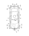
- FIG. 1 is a diagram illustrating components of a vehicle (hereinafter referred to as a host vehicle M) on which the vehicle control system 100 of the embodiment is mounted.
- the vehicle on which the vehicle control system 100 is mounted is, for example, an automobile such as a two-wheel, three-wheel, or four-wheel vehicle.
- a hybrid vehicle having an internal combustion engine and an electric motor.
- An electric vehicle is driven using electric power discharged by a battery such as a secondary battery, a hydrogen fuel cell, a metal fuel cell, or an alcohol fuel cell.
- the host vehicle M includes sensors such as a finder 20-1 to 20-7, radars 30-1 to 30-6, and a camera 40, a navigation device 50, and a vehicle control system 100. Installed.
- the finders 20-1 to 20-7 are, for example, LIDARs (Light Detection and Ranging or Laser Imaging Detection and Ranging) that measure the scattered light with respect to the irradiation light and measure the distance to the target.
- LIDARs Light Detection and Ranging or Laser Imaging Detection and Ranging
- the finder 20-1 is attached to a front grill or the like
- the finders 20-2 and 20-3 are attached to a side surface of a vehicle body, a door mirror, the inside of a headlamp, a side lamp, and the like.
- the finder 20-4 is attached to a trunk lid or the like
- the finders 20-5 and 20-6 are attached to the side surface of the vehicle body, the interior of the taillight, or the like.
- the above-described viewfinders 20-1 to 20-6 have a detection area of about 150 degrees in the horizontal direction, for example.
- the finder 20-7 is attached to a roof or the like.
- the finder 20-7 has a detection area of 360 degrees in the horizontal direction, for example.
- Radars 30-1 and 30-4 are, for example, long-distance millimeter-wave radars that have a wider detection area in the depth direction than other radars.
- Radars 30-2, 30-3, 30-5, and 30-6 are medium-range millimeter-wave radars that have a narrower detection area in the depth direction than radars 30-1 and 30-4.
- finders 20-1 to 20-7 are not particularly distinguished, they are simply referred to as “finder 20”, and when the radars 30-1 to 30-6 are not particularly distinguished, they are simply referred to as “radar 30”.
- the radar 30 detects an object by, for example, FM-CW (Frequency Modulated Continuous Wave) method.
- FM-CW Frequency Modulated Continuous Wave
- the camera 40 is a digital camera using an individual image sensor such as a CCD (Charge Coupled Device) or a CMOS (Complementary Metal Oxide Semiconductor).
- the camera 40 is attached to the upper part of the front windshield, the rear surface of the rearview mirror, or the like. For example, the camera 40 periodically images the front of the host vehicle M repeatedly.
- the camera 40 may be a stereo camera including a plurality of cameras.
- FIG. 1 is merely an example, and a part of the configuration may be omitted, or another configuration may be added.
- FIG. 2 is a functional configuration diagram centering on the vehicle control system 100 according to the embodiment.
- the host vehicle M includes a detection device DD including a finder 20, a radar 30 and a camera 40, a navigation device 50, a communication device 55, a vehicle sensor 60, an HMI (Human Machine Interface) 70, and a vehicle control system. 100, a driving force output device 200, a steering device 210, and a brake device 220 are mounted. These devices and devices are connected to each other by a multiple communication line such as a CAN (Controller Area Network) communication line, a serial communication line, a wireless communication network, or the like.
- the vehicle control system in the claims does not only indicate “vehicle control system 100”, but may include a configuration other than the vehicle control system 100 (detection device DD, HMI 70, etc.).
- the navigation device 50 includes a GNSS (Global Navigation Satellite System) receiver, map information (navigation map), a touch panel display device that functions as a user interface, a speaker, a microphone, and the like.
- the navigation device 50 identifies the position of the host vehicle M using the GNSS receiver, and derives a route from the position to the destination specified by the user.
- the route derived by the navigation device 50 is provided to the target lane determining unit 110 of the vehicle control system 100.
- the position of the host vehicle M may be specified or supplemented by INS (Inertial Navigation System) using the output of the vehicle sensor 60.
- the navigation device 50 guides the route to the destination by voice or navigation display.
- the configuration for specifying the position of the host vehicle M may be provided independently of the navigation device 50.
- the navigation apparatus 50 may be implement
- information is transmitted and received between the terminal device and the vehicle control system 100 by wireless or wired communication.
- the communication device 55 performs wireless communication using, for example, a cellular network, a Wi-Fi network, Bluetooth (registered trademark), DSRC (Dedicated Short Range Communication), or the like.
- the vehicle sensor 60 includes a vehicle speed sensor that detects a vehicle speed, an acceleration sensor that detects acceleration, a yaw rate sensor that detects an angular velocity around a vertical axis, a direction sensor that detects the direction of the host vehicle M, and the like.
- FIG. 3 is a configuration diagram of the HMI 70.
- the HMI 70 includes, for example, a driving operation system configuration and a non-driving operation system configuration. These boundaries are not clear, and the configuration of the driving operation system may have a non-driving operation system function (or vice versa).
- Part of the HMI 70 is an example of an “operation receiving unit” that receives an operation of a vehicle occupant of the host vehicle M, and an example of an “output unit” that outputs information.
- the HMI 70 includes a driving force output device 200, a steering device 210, a brake device 220, and other driving operation devices 81 as shown in FIG.
- the traveling driving force output device 200, the steering device 210, and the brake device 220 travel the vehicle by automatic driving or manual driving under the control of the vehicle control system 100. Specific examples of the travel driving force output device 200, the steering device 210, and the brake device 220 will be described later.
- Other driving operation device 81 is, for example, a shift lever or a shift position sensor.
- the soft lever is a manipulator for receiving an instruction to change the shift stage by a vehicle occupant.
- the shift position sensor detects a shift stage instructed by the vehicle occupant using the shift lever, and outputs a shift position signal indicating the detection result to the vehicle control system 100.
- the other operation device 81 is, for example, a joystick, a button, a dial switch, a GUI (Graphical User Interface) switch, or the like.
- the other driving operation device 81 receives an acceleration instruction, a deceleration instruction, a turning instruction, and the like, and outputs them to the vehicle control system 100.
- the HMI 70 has, for example, a display device 82, a speaker 83, a contact operation detection device 84 and a content reproduction device 85, various operation switches 86, a sheet 88 and a sheet driving device 89, and a window glass 90. And a window drive device 91 and a vehicle interior camera 95.
- the display device 82 is, for example, an LCD (Liquid Crystal Display), an organic EL (Electro Luminescence) display device, or the like that is attached to each part of the instrument panel, an arbitrary position facing the passenger seat or the rear seat.
- the display device 82 is a display located in front of a vehicle occupant who operates the host vehicle M.
- the display device 82 may be, for example, a HUD (Head Up Display) that projects an image on a front windshield or other window.
- the speaker 83 outputs sound.
- the contact operation detection device 84 detects a contact position (touch position) on the display screen of the display device 82 and outputs it to the vehicle control system 100.
- the contact operation detection device 84 may be omitted.
- the content playback device 85 includes, for example, a DVD (Digital Versatile Disc) playback device, a CD (Compact Disc) playback device, a television receiver, and various guide image generation devices.
- the display device 82, the speaker 83, the contact operation detection device 84, and the content playback device 85 may have a configuration in which a part or all of them are common to the navigation device 50. Further, the navigation device 50 may be included in the HMI 70.
- the various operation switches 86 are arranged at arbitrary locations in the passenger compartment.
- the various operation switches 86 include an automatic driving changeover switch 87A for instructing the start (or future start) and stop of automatic driving, and each output unit (for example, the navigation device 50, the display device) while the vehicle occupant grips the steering wheel. 82, a content reproduction device 85) or the like, and a steering switch 87B for setting display contents and switching screens.
- the automatic operation changeover switch 87A and the steering switch 87B may be either a GUI (Graphical User Interface) switch or a mechanical switch.
- the various operation switches 86 may include switches for driving the sheet driving device 89 and the window driving device 91.
- the various operation switches 86 output an operation signal to the vehicle control system 100 when an operation from a vehicle occupant is received.
- the seat 88 is a seat on which a vehicle occupant is seated.
- the seat driving device 89 freely drives the reclining angle, the front-rear direction position, the yaw angle, and the like of the seat 88.
- the window glass 90 is provided at each door, for example.
- the window driving device 91 drives the window glass 90 to open and close.
- the vehicle interior camera 95 is a digital camera using an individual image sensor such as a CCD or CMOS.
- the vehicle interior camera 95 is attached to a position where an image of at least the head of a vehicle occupant who performs a driving operation, such as a rearview mirror, a steering boss, or an instrument panel, can be taken.
- a driving operation such as a rearview mirror, a steering boss, or an instrument panel.
- the camera 40 periodically and repeatedly images the vehicle occupant.
- FIG. 4 is a diagram illustrating a functional configuration example of the traveling driving force output device 200.
- the travel driving force output device 200 shown in FIG. 4 includes an accelerator pedal 200A, an accelerator opening sensor 200B, an engine ECU (Electronic Control Unit) 200C, an accelerator pedal reaction force control unit 200D, a reaction force motor 200E, The control unit 200F, the speed change mechanism 200G, and the throttle valve drive unit 200H may be included, but are not limited thereto.
- a combination of the accelerator pedal reaction force control unit 200D and the reaction force motor 200E is an example of an accelerator pedal reaction force output device.
- the accelerator pedal 200A is an operator for receiving an acceleration instruction (or a deceleration instruction by a return operation) by a vehicle occupant of the host vehicle M.
- the accelerator opening sensor 200B detects the depression amount of the accelerator pedal 200A and outputs an accelerator opening signal indicating the depression amount.
- the host vehicle M when the host vehicle M is an automobile having an internal combustion engine as a power source, the engine, a transmission, and an engine ECU 200C for controlling the engine are provided.
- the host vehicle M is an electric vehicle using an electric motor as a power source, a traveling motor is provided instead of the engine and transmission described above, and a motor ECU is provided instead of the engine ECU 200C.
- the host vehicle M when the host vehicle M is a hybrid vehicle, it includes the above-described engine, transmission, and engine ECU, and a travel motor and motor ECU.
- Engine ECU 200C generates a control signal for adjusting a shift stage and the like in transmission mechanism 200G according to information input from travel control unit 160 described later, and outputs the generated control signal to transmission control unit 200F.
- the driving force output device 200 adjusts the throttle opening of the throttle valve of the engine and outputs a drive signal to the throttle valve drive unit 200H.
- traveling driving force output device 200 includes only the traveling motor
- the motor ECU is provided instead of the engine ECU 200C described above.
- the motor ECU adjusts the duty ratio of the PWM signal applied to the traveling motor according to the information input from the traveling control unit 160.
- traveling drive force output device 200 includes an engine and a travel motor
- engine ECU 200C and motor ECU control the travel drive force in cooperation with each other according to information input from travel control unit 160.
- engine ECU 200C outputs to the accelerator pedal 200A a force (reaction force) in a direction opposite to the force (depression force) that depresses accelerator pedal 200A corresponding to the accelerator opening signal obtained from accelerator opening sensor 200B.
- the reaction force control signal is output to the accelerator pedal reaction force control unit 200D.
- the accelerator pedal reaction force control unit 200D generates a drive signal for controlling the drive to the reaction force motor 200E for creating the reaction force to the accelerator pedal 200A based on the reaction force control signal from the engine ECU 200C.
- the accelerator pedal reaction force control unit 200D causes the accelerator pedal 200A to apply a reaction force having an arbitrary magnitude according to the stroke amount, the stroke speed, or other signals, for example, by the torque generated by the reaction force motor 200E.
- the reaction force motor 200E outputs a reaction force against the pedal force of the vehicle occupant to the accelerator pedal 200A based on a drive signal from the accelerator pedal reaction force control unit 200D.
- the gear shift control unit 200F sends gear shift information to the gear shift mechanism 200G based on the gear shift command from the engine ECU 200C to control the gear shift.
- the speed change mechanism 200G changes the speed of the host vehicle M.
- the throttle valve drive unit 200H opens and closes the throttle valve according to a drive signal from the engine ECU 200C, and changes the throttle opening corresponding to the accelerator opening sensor 200B.
- Engine ECU 200C performs the various controls in cooperation with the vehicle control system 100.
- Engine ECU 200C may be a separate computer device from vehicle control system 100, or may be a single integrated computer device.
- FIG. 5 is a diagram illustrating a functional configuration example of the steering device 210.
- the steering device 210 includes a steering wheel 210A, a steering shaft 210B, a steering steering angle sensor 210C, a steering torque sensor 210D, a reaction force motor 210E, an assist motor 210F, a steering mechanism 210G, and a steering angle sensor 210H.
- the steering ECU 210I may be included, but is not limited thereto.
- the steering wheel 210A is an example of an operator that receives a steering instruction from a vehicle occupant. Instead of the steering wheel 210A, another type of operation device such as a joystick may be mounted. An operation performed on the steering wheel 210A is transmitted to the steering shaft 210B. A steering angle sensor 210C and a steering torque sensor 210D are attached to the steering shaft 210B. The steering angle sensor 210C detects the angle at which the steering wheel 210A is operated and outputs the detected angle to the steering ECU 210I. The steering torque sensor 210D detects torque (steering torque) acting on the steering shaft 210B and outputs it to the steering ECU 210I. The reaction force motor 210E outputs an operation reaction force to the steering wheel 210A by outputting torque to the steering shaft 210B under the control of the steering ECU 210I.
- the assist motor 210F outputs a torque to the steering mechanism 210G under the control of the steering ECU 210I to generate a steering force in the steering mechanism 210G.
- the steered mechanism 210G is, for example, a rack and pinion mechanism.
- the steering angle sensor 210H detects an amount (for example, rack stroke) indicating the angle (steering angle) of the steering mechanism 210G and outputs the detected amount to the steering ECU 210I.
- the steering shaft 210B and the steering mechanism 210G may be fixedly connected, disconnected, or connected via a clutch mechanism or the like.
- the steering ECU 210I performs the above-described various controls in cooperation with the vehicle control system 100.
- the steering ECU 210I may be a computer device that is separate from the vehicle control system 100, or may be a single integrated computer device.
- FIG. 6 is a diagram illustrating a functional configuration example of the brake device 220.
- the brake device 220 shown in FIG. 6 may include a brake pedal 220A, a pedal force sensor 220B, a brake ECU 220C, a brake reaction force control unit 220D, a reaction force motor 220E, and a brake mechanism 220F, but is not limited thereto. Not.
- the brake pedal 220A is an operator for receiving a deceleration instruction from the vehicle occupant.
- the pedaling force sensor 220B detects a pedaling force (or a pedaling amount) applied to the brake pedal 220A, and outputs a brake signal indicating the detection result to the brake ECU 220C.
- the brake ECU 220C generates a control signal for controlling the operation of the reaction force motor 220E based on the depression force of the brake pedal 220A detected by the depression force sensor 220B.
- the brake ECU 220C controls the operation of the brake mechanism 220F such as a brake actuator based on the pedaling force of the brake pedal 220A detected by the pedaling force sensor 220B.
- the brake reaction force control unit 220D controls the reaction force output to the brake pedal 220A via the reaction force motor 220E based on a control signal from the brake ECU 200C.
- the reaction force motor 220E generates torque under the control of the brake reaction force control unit 220D, and outputs the reaction force of any magnitude according to the stroke amount, stroke speed or other signal to the brake pedal 220A. To do.
- the reaction force motor 220E has a function of generating a reaction force with respect to the operation of the brake pedal 220A and a function of changing the stroke start pedaling force of the brake pedal 220A.
- the brake ECU 220C described above performs the various controls in cooperation with the vehicle control system 100.
- the brake ECU 220C may be a computer device that is separate from the vehicle control system 100, or may be a single integrated computer device.
- the travel driving force output device 200, the steering device 210, and the brake device 220 described above can apply a reaction force to the accelerator pedal 200A, the steering wheel 210A, and the brake pedal 220A, respectively.
- the reaction force can be applied so that the vehicle occupant of the host vehicle M does not perform an erroneous override.
- the accelerator pedal 200A and the brake pedal 220A can be used as a footrest (foot stand) during automatic driving
- the steering wheel 210A can be used as an arm rest (arm stand).
- the vehicle control system 100 is realized by, for example, one or more processors or hardware having an equivalent function.
- the vehicle control system 100 includes a combination of a processor such as a CPU (Central Processing Unit), a storage device, and an ECU (Electronic Control Unit) in which a communication interface is connected by an internal bus, or an MPU (Micro-Processing Unit). It may be.
- a processor such as a CPU (Central Processing Unit), a storage device, and an ECU (Electronic Control Unit) in which a communication interface is connected by an internal bus, or an MPU (Micro-Processing Unit). It may be.
- the vehicle control system 100 includes, for example, a target lane determination unit 110, an automatic driving control unit 120, a travel control unit 160, an HMI control unit (interface control unit) 170, and a storage unit 180.
- the automatic driving control unit 120 includes, for example, an automatic driving mode control unit 130, an own vehicle position recognition unit 140, an external environment recognition unit 142, an action plan generation unit 144, a track generation unit 146, and a switching control unit 150. Prepare.
- Part or all of the target lane determining unit 110, the automatic operation control unit 120, and the travel control unit 160 are realized by a processor executing a program (software). Some or all of these may be realized by hardware such as LSI (Large Scale Integration) or ASIC (Application Specific Integrated Circuit), or may be realized by a combination of software and hardware.
- LSI Large Scale Integration
- ASIC Application Specific Integrated Circuit
- the storage unit 180 stores, for example, high-accuracy map information 182, target lane information 184, action plan information 186, override threshold value 188, mode-specific operation availability information 190, and the like.
- the storage unit 180 is realized by a ROM (Read Only Memory), a RAM (Random Access Memory), an HDD (Hard Disk Drive), a flash memory, or the like.
- the program executed by the processor may be stored in the storage unit 180 in advance, or may be downloaded from an external device via an in-vehicle Internet facility or the like.
- the program may be installed in the storage unit 180 by mounting a portable storage medium storing the program on a drive device (not shown).
- the computer (vehicle-mounted computer) of the vehicle control system 100 may be distributed by a plurality of computer devices.
- the target lane determining unit 110 is realized by an MPU, for example.
- the target lane determination unit 110 divides the route provided from the navigation device 50 into a plurality of blocks (for example, every 100 [m] with respect to the vehicle traveling direction), and refers to the high-precision map information 182 for each block.
- the target lane determination unit 110 performs determination such as how many lanes from the left are to be traveled.
- the target lane determination unit 110 determines the target lane so that the host vehicle M can travel on a reasonable travel route for proceeding to the branch destination when there is a branch point or a merge point in the route.
- the target lane determined by the target lane determining unit 110 is stored in the storage unit 180 as target lane information 184.
- the high-precision map information 182 is map information with higher accuracy than the navigation map that the navigation device 50 has.
- the high-precision map information 182 includes, for example, information on the center of the lane or information on the boundary of the lane.
- the high-precision map information 182 may include road information, traffic regulation information, address information (address / postal code), facility information, telephone number information, and the like.
- Road information includes information indicating the type of road such as expressway, toll road, national road, prefectural road, road lane number, width of each lane, road gradient, road position (longitude, latitude, height). Information including 3D coordinates), curvature of lane curves, lane merging and branch point positions, signs provided on roads, and the like.
- the traffic regulation information includes information that the lane is blocked due to construction, traffic accidents, traffic jams, or the like.
- the automatic operation control unit 120 automatically performs at least one of speed control and steering control of the host vehicle M.
- the speed control is control related to acceleration / deceleration of the host vehicle M, for example, and acceleration / deceleration includes one or both of acceleration and deceleration. Further, the automatic operation control unit 120 performs control to automatically switch from automatic operation to manual operation based on an operation received by an operation reception unit such as the HMI 70.
- the automatic operation mode control unit 130 determines an automatic operation mode performed by the automatic operation control unit 120.
- the automatic driving modes in the present embodiment include the following different modes. In addition, the following is an example to the last, and the mode number of automatic driving
- Mode A is the mode with the highest degree of automatic driving. When mode A is implemented, since all vehicle control such as complicated merge control is automatically performed, the vehicle occupant does not need to monitor the surroundings and state of the host vehicle M.
- Mode B is a mode in which the degree of automatic driving is the second highest after Mode A.
- mode B is implemented, in principle, all vehicle control is performed automatically, but the driving operation of the host vehicle M is left to the vehicle occupant depending on the situation. For this reason, the vehicle occupant needs to monitor the periphery and state of the own vehicle M.
- Mode C is a mode in which the degree of automatic driving is the second highest after mode B.
- mode C the vehicle occupant needs to perform confirmation operation according to the scene with respect to HMI70.
- mode C for example, when the vehicle occupant is notified of the lane change timing and the vehicle occupant performs an operation to instruct the HMI 70 to change the lane, the automatic lane change is performed. For this reason, the vehicle occupant needs to monitor the periphery and state of the own vehicle M.
- the automatic driving mode control unit 130 determines the mode of automatic driving based on the operation of the vehicle occupant with respect to the HMI 70, the event determined by the action plan generation unit 144, the travel mode determined by the trajectory generation unit 146, and the like.
- the automatic operation mode is notified to the HMI control unit 170.
- the limit according to the performance etc. of the detection device DD of the own vehicle M may be set to the mode of automatic driving. For example, when the performance of the detection device DD is low, the mode A may not be performed. In any mode, it is possible to switch to the manual operation mode (override) by an operation on the configuration of the driving operation system in the HMI 70.
- the vehicle position recognition unit 140 is based on the high-precision map information 182 stored in the storage unit 180 and information input from the finder 20, the radar 30, the camera 40, the navigation device 50, or the vehicle sensor 60.
- the lane in which the vehicle M is traveling (the traveling lane) and the relative position of the host vehicle M with respect to the traveling lane are recognized.
- the own vehicle position recognition unit 140 is, for example, a road lane line pattern recognized from the high-precision map information 182 (for example, an arrangement of solid lines and broken lines) and the periphery of the own vehicle M recognized from an image captured by the camera 40.
- the road lane is recognized by comparing the road lane marking pattern. In this recognition, the position of the host vehicle M acquired from the navigation device 50 and the processing result by INS may be taken into account.
- FIG. 7 is a diagram illustrating a state where the vehicle position recognition unit 140 recognizes the relative position of the vehicle M with respect to the travel lane L1.
- the own vehicle position recognition unit 140 makes a deviation OS of the reference point (for example, the center of gravity) of the own vehicle M from the travel lane center CL and a line connecting the travel lane center CL in the traveling direction of the own vehicle M.
- the angle ⁇ is recognized as a relative position of the host vehicle M with respect to the traveling lane L1.
- the host vehicle position recognition unit 140 recognizes the position of the reference point of the host vehicle M with respect to any side end of the host lane L1 as the relative position of the host vehicle M with respect to the traveling lane. Also good.
- the relative position of the host vehicle M recognized by the host vehicle position recognition unit 140 is provided to the target lane determination unit 110.
- the external environment recognition unit 142 recognizes the position, speed, acceleration, and other states of surrounding vehicles based on information input from the finder 20, the radar 30, the camera 40, and the like.
- the peripheral vehicle is, for example, a vehicle that travels around the host vehicle M and travels in the same direction as the host vehicle M.
- the position of the surrounding vehicle may be represented by a representative point such as the center of gravity or corner of the other vehicle, or may be represented by a region expressed by the contour of the other vehicle.
- the “state” of the surrounding vehicle may include the acceleration of the surrounding vehicle, whether the lane is changed (or whether the lane is going to be changed), which is grasped based on the information of the various devices.
- the outside recognition unit 142 recognizes the positions of guardrails, utility poles, parked vehicles, pedestrians, fallen objects, railroad crossings, traffic lights, signboards and other objects installed near construction sites. May be.
- the action plan generation unit 144 sets a starting point of automatic driving and / or a destination of automatic driving.
- the starting point of the automatic driving may be the current position of the host vehicle M or a point where an operation for instructing automatic driving is performed.
- the action plan generation unit 144 generates an action plan in a section between the start point and the destination for automatic driving. In addition, not only this but the action plan production
- the action plan is composed of a plurality of events that are executed sequentially, for example.
- Examples of the event include a deceleration event for decelerating the host vehicle M, an acceleration event for accelerating the host vehicle M, a lane keeping event for driving the host vehicle M so as not to deviate from the traveling lane, and a lane change event for changing the traveling lane.
- the action plan generation unit 144 sets a lane change event, a branch event, or a merge event at a location where the target lane determined by the target lane determination unit 110 is switched. Information indicating the action plan generated by the action plan generation unit 144 is stored in the storage unit 180 as action plan information 186.
- FIG. 8 is a diagram showing an example of an action plan generated for a certain section.
- the action plan generation unit 144 generates an action plan necessary for the host vehicle M to travel on the target lane indicated by the target lane information 184.
- the action plan generation unit 144 may dynamically change the action plan regardless of the target lane information 184 according to a change in the situation of the host vehicle M.
- the action plan generation unit 144 may determine that the speed of the surrounding vehicle recognized by the external recognition unit 142 exceeds the threshold while the vehicle travels, or the movement direction of the surrounding vehicle traveling in the lane adjacent to the own lane is the own lane direction.
- the event set in the driving section where the host vehicle M is scheduled to travel is changed.
- the vehicle from the rear of the lane to which the lane is changed becomes greater than the threshold during the lane keep event according to the recognition result of the external recognition unit 142.
- the action plan generation unit 144 may change the event next to the lane keep event from a lane change event to a deceleration event, a lane keep event, or the like. As a result, the vehicle control system 100 can automatically drive the host vehicle M safely even when a change occurs in the external environment.
- FIG. 9 is a diagram illustrating an example of the configuration of the trajectory generation unit 146.
- the track generation unit 146 includes, for example, a travel mode determination unit 146A, a track candidate generation unit 146B, and an evaluation / selection unit 146C.
- the travel mode determination unit 146A determines one of the travel modes from constant speed travel, follow-up travel, low-speed follow-up travel, deceleration travel, curve travel, obstacle avoidance travel, and the like. . For example, when there is no other vehicle ahead of the host vehicle M, the travel mode determination unit 146A determines the travel mode to be constant speed travel. In addition, the traveling mode determination unit 146A determines the traveling mode to follow running when traveling following the preceding vehicle. In addition, the traveling mode determination unit 146A determines the traveling mode to be low-speed following traveling in a traffic jam scene or the like.
- the travel mode determination unit 146A determines the travel mode to be decelerated when the external environment recognition unit 142 recognizes deceleration of the preceding vehicle or when an event such as stopping or parking is performed. In addition, when the outside recognition unit 142 recognizes that the host vehicle M has reached a curved road, the travel mode determination unit 146A determines the travel mode to be curved travel. In addition, the travel mode determination unit 146A determines the travel mode to be obstacle avoidance travel when the external environment recognition unit 142 recognizes an obstacle in front of the host vehicle M.
- the trajectory candidate generation unit 146B generates trajectory candidates based on the travel mode determined by the travel mode determination unit 146A.
- FIG. 10 is a diagram illustrating an example of trajectory candidates generated by the trajectory candidate generation unit 146B.
- FIG. 10 shows candidate tracks generated when the host vehicle M changes lanes from the lane L1 to the lane L2.
- the trajectory candidate generation unit 146B follows a trajectory as shown in FIG. 10, for example, at a target position (orbit point K) at which the reference position (for example, the center of gravity or the center of the rear wheel axis) of the host vehicle M should arrive at every future predetermined time. Determine as a gathering of.
- FIG. 11 is a diagram in which trajectory candidates generated by the trajectory candidate generation unit 146B are expressed by trajectory points K.
- the trajectory candidate generation unit 146B gradually widens the distance between the trajectory points K when it wants to accelerate and gradually narrows the distance between the trajectory points when it wants to decelerate.
- the trajectory candidate generation unit 146B needs to give a target speed to each of the trajectory points K.
- the target speed is determined according to the travel mode determined by the travel mode determination unit 146A.
- the track candidate generation unit 146B first sets a lane change target position (or a merge target position).
- the lane change target position is set as a relative position with respect to the surrounding vehicles, and determines “with which surrounding vehicle the lane is to be changed”.
- the trajectory candidate generation unit 146B pays attention to three surrounding vehicles with the lane change target position as a reference, and determines a target speed when the lane change is performed.
- FIG. 12 is a diagram showing the lane change target position TA.
- L1 represents the own lane and L2 represents the adjacent lane.
- the preceding vehicle mA is set as the surrounding vehicle that runs immediately before the own vehicle M
- the front reference vehicle mB and the lane change target position TA is set as the surrounding vehicle that runs immediately before the lane changing target position TA.
- a surrounding vehicle traveling immediately after is defined as a rear reference vehicle mC.
- the host vehicle M needs to perform acceleration / deceleration in order to move to the side of the lane change target position TA. However, it is necessary to avoid catching up with the preceding vehicle mA at this time. For this reason, the trajectory candidate generation unit 146B predicts the future state of the three neighboring vehicles and determines the target speed so as not to interfere with each neighboring vehicle.
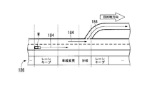
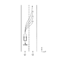
- FIG. 13 is a diagram showing a speed generation model when the speeds of the three surrounding vehicles are assumed to be constant.
- straight lines extending from mA, mB, and mC indicate displacements in the traveling direction when it is assumed that the respective surrounding vehicles have traveled at a constant speed.
- the own vehicle M must be between the front reference vehicle mB and the rear reference vehicle mC at the point CP at which the lane change is completed, and must be behind the preceding vehicle mA before that.
- the track candidate generation unit 146B derives a plurality of time-series patterns of the target speed until the lane change is completed. Then, a plurality of trajectory candidates as shown in FIG.
- the motion patterns of the three surrounding vehicles are not limited to the constant speed as shown in FIG. 13 but may be predicted on the assumption of a constant acceleration and a constant jerk (jumping degree).
- the evaluation / selection unit 146C evaluates the track candidates generated by the track candidate generation unit 146B from, for example, two viewpoints of planability and safety, and selects a track to be output to the travel control unit 160. .
- the viewpoint of planability for example, the track is highly evaluated when the followability with respect to an already generated plan (for example, an action plan) is high and the total length of the track is short.
- an already generated plan for example, an action plan
- a trajectory in which the lane is once changed in the left direction and returned is evaluated as low.
- viewpoint of safety for example, at each track point, the distance between the host vehicle M and the object (peripheral vehicle or the like) is longer, and the higher the acceleration / deceleration or the change amount of the steering angle, the higher the evaluation.
- the switching control unit 150 switches between the automatic operation mode and the manual operation mode based on the signal input from the automatic operation switch 87A. Further, the switching control unit 150 performs control to switch from the automatic operation mode to the manual operation mode based on the speed (one or both of acceleration and deceleration) with respect to the configuration of the driving operation system in the HMI 70 or an operation instructing steering. .
- the switching control unit 150 includes an operation amount indicated by a signal input from the configuration of a driving operation system (for example, at least one of the travel driving force output device 200, the steering device 210, and the brake device 220) in the HMI 70;
- the operation amount threshold value (override threshold value 188) stored in the storage unit 180 is compared.
- the operation amount includes, for example, the magnitude of the operating force, the distance changed by the operation, the magnitude of the angle, and the like.
- the operation amount obtained from the travel driving force output device 200 is, for example, information on the accelerator opening based on the operation of the vehicle occupant detected by the accelerator opening sensor 200B.
- the operation amount obtained from the steering device 210 is, for example, information related to the steering angle based on the operation of the vehicle occupant detected by the steering steering angle sensor 210C.
- the operation amount obtained from the brake device 220 is, for example, information related to the pedaling force based on the operation of the vehicle occupant detected by the pedaling force sensor 220B.
- the switching control unit 150 performs override control for switching from the automatic operation mode to the manual operation mode when the operation amount described above exceeds the threshold value. For example, the switching control unit 150 performs the override control when the value obtained by subtracting the threshold from the operation amount described above is less than 0, or when the value (ratio, ratio) obtained by dividing the operation amount by the threshold exceeds 1. Do. Further, the switching control unit 150 may perform the above-described override control when the state where the operation amount exceeds the threshold value continues for a reference time or longer.
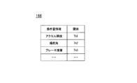
- FIG. 14 is a diagram illustrating an example of the override threshold value 188.
- examples of the override threshold value 188 include “operation amount information” and “threshold value”, but are not limited thereto.
- a threshold value other than the override threshold value may be set and compared with the set value.
- the “operation amount information” is information regarding the operation amount generated in the operation reception unit as a result of, for example, a vehicle occupant operating the operation reception unit.
- An example of the operation reception unit is at least one of the accelerator pedal 200A, the steering wheel 210A, and the brake pedal 220A.
- Examples of the operation amount information include, but are not limited to, an accelerator opening degree with respect to the accelerator pedal 200A, a steering angle with respect to the steering wheel 210A, a brake depression amount with respect to the brake pedal 220A, and the like.
- threshold values Th1 to Th3 are set for the respective operation amount information described above.
- the switching control unit 150 compares the operation amount associated with the accelerator opening, the steering angle, and the brake pedal depression amount actually acquired by the driving operation of the vehicle occupant with the operation amount threshold value stored in the override threshold value 188. Based on the comparison result, the above-described override control is performed.
- the switching control unit 150 outputs information indicating the comparison result to the HMI control unit 170.
- the information indicating the comparison result includes, for example, the information regarding the operation amount described above, the information regarding the threshold value of the operation amount, the information regarding the comparison result, and the like, but is not limited thereto. Further, the switching control unit 150 may return to the automatic operation mode when an operation for the configuration of the driving operation system in the HMI 70 is not detected for a predetermined time after switching to the manual operation mode by the override. .
- the traveling control unit 160 automatically performs at least one of speed control and steering control of the host vehicle M based on the schedule determined by the action plan generation unit 144 and the track generation unit 146 described above.
- the traveling control unit 160 includes the traveling driving force output device 200 such that the host vehicle M passes the traveling track (trajectory information) generated (scheduled) by the track generating unit 146 at a scheduled time.
- the steering device 210 and the brake device 220 are controlled.
- the HMI control unit 170 includes an operation amount related to acceleration control and / or steering control from the vehicle occupant of the host vehicle M received from the driving operation system of the HMI 70, and an operation amount for performing control for switching from automatic driving to manual driving. Information indicating the relationship with the threshold is output to an output unit or the like.
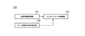
- FIG. 15 is a diagram illustrating a functional configuration example of the HMI control unit 170.
- the HMI control unit 170 includes a comparison information acquisition unit 172, an interface control unit 174, and a mode-specific operation availability determination unit 176.
- the comparison information acquisition unit 172 receives from the vehicle occupant of the host vehicle M received from the above-described switching control unit 150 from the driving operation system of the HMI 70 (for example, the travel driving force output device 200, the steering device 210, and the brake device 220).
- the information which shows the relationship between the operation amount regarding this acceleration control and / or steering control, and the threshold value of the operation amount at which the control for switching from the automatic operation to the manual operation is performed is acquired.
- the comparison information acquisition unit 172 acquires information indicating a result of comparing the operation amount and the threshold value as information indicating the relationship between the operation amount and the threshold value.
- the interface control unit 174 outputs the information acquired by the comparison information acquisition unit 172 from the output unit, and notifies the vehicle occupant of the host vehicle M.
- An example of the output unit includes at least one of the navigation device 50, the display device 82, the speaker 83, and the like.
- the interface control unit 174 outputs information indicating the relationship between the above-described operation amount and the operation amount threshold value to the output unit that can be operated by the vehicle occupant in the operation mode by the mode-specific operation availability determination unit 176. You may control to make it. In this way, by displaying information on the operation status on the output unit that is likely to be viewed by the vehicle occupant, the vehicle occupant can be more surely grasped.
- the mode-specific operation propriety determination unit 176 refers to the mode-specific operation propriety information 190 and determines the HMI 70 (non- It is determined whether the operation of the driving operation system) is possible.
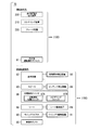
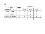
- FIG. 16 is a diagram illustrating an example of the operation availability information 190 by mode.
- the mode-specific operation availability information 190 shown in FIG. 16 includes “manual operation mode” and “automatic operation mode” as operation mode items. Further, the “automatic operation mode” includes the above-mentioned “mode A”, “mode B”, “mode C”, and the like.
- the mode-specific operation availability information 190 includes “navigation operation” that is an operation on the navigation device 50, “content reproduction operation” that is an operation on the content reproduction device 85, and an operation on the display device 82 as non-driving operation items. It has a certain "instrument panel operation” etc.
- whether or not the vehicle occupant can operate the non-driving operation system is set for each operation mode described above, but the target interface device (display unit or the like) It is not limited to.
- the mode-specific operation propriety determination unit 176 refers to the mode-specific operation propriety information 190 based on the mode information acquired from the automatic operation control unit 120, thereby permitting use of the plurality of output devices included in the output unit. Output devices to be used and output devices that are not permitted to be used. Further, the mode-specific operation availability determination unit 176 outputs the determination result to the interface control unit 174. Accordingly, the interface control unit 174 controls whether or not an operation from the vehicle occupant can be accepted for the non-driving operation type HMI 70 and the like.
- the vehicle occupant when the operation mode executed by the vehicle control system 100 is the manual operation mode, the vehicle occupant operates the driving operation system (for example, the accelerator pedal 200A, the steering wheel 210A, the brake pedal 220A, etc.) of the HMI 70.
- the driving operation system for example, the accelerator pedal 200A, the steering wheel 210A, the brake pedal 220A, etc.
- the interface control unit 174 Control is performed so as not to accept operations for some or all of the non-driving operation systems.
- the interface control unit 174 performs control so as not to accept an operation on a part or all of the non-driving operation system of the HMI 70 in order to prevent driver distraction.
- the interface control unit 174 performs control to relax the restriction of the driver distraction and to accept the operation of the vehicle occupant for the non-driving operation system that has not received the operation.
- the interface control unit 174 displays video on the display device 82, which is an example of a plurality of output devices included in the output unit, outputs audio to the speaker 83, and outputs content from a DVD or the like to the content reproduction device 85. Play it.
- the content reproduced by the content reproduction device 85 may include, for example, various contents related to entertainment and entertainment such as a TV program in addition to the content stored on the DVD or the like.
- the “content reproduction operation” shown in FIG. 16 may mean such a content operation related to entertainment and entertainment.
- instrument panel operation can also be operated in mode C.
- the display device 82 corresponding to the instrument panel is a display located in front of a vehicle occupant who operates the host vehicle M, for example.
- the display device 82 can accept the operation of the vehicle occupant when the mode with the lowest degree of automatic driving is executed among the automatic driving modes (mode A to mode C).
- the interface control unit 174 causes the display device 82 to output information indicating the relationship between the operation amount and the threshold value when, for example, automatic driving in mode C is executed.
- the interface control unit 174 can select an output device that outputs information indicating the relationship between the operation amount and the threshold value according to the operation mode, and cause the selected output device to output the above-described information. Accordingly, the interface control unit 174 can display information on an output device that is likely to be viewed by a vehicle occupant, for example.
- FIG. 17 is a diagram illustrating a first example in which information indicating the relationship between the operation amount and the threshold value is output.
- information indicating the relationship between the operation amount and the threshold value is output.
- FIG. 17 for example, an example displayed on the screen of the display device 82 is shown, but it may be displayed on another output unit such as the navigation device 50.
- the ratio of the depression force of the brake pedal 220 ⁇ / b> A until the override control is performed on the screen 300 of the display device 82 as the information indicating the result of comparing the operation amount and the threshold is the character information 310. It is shown in Examples of the character information 310 include “90% remaining until overriding” as shown in FIG. 17A, but are not limited to this. For example, “current depression amount 50”, “manual operation” Various messages such as “the stepping angle until switching to 12 °” may be used.
- the interface control unit 174 may display an image 320 in which a foot is placed on the brake pedal 220A so that a vehicle occupant of the host vehicle can easily understand visually. In this case, it is preferable to display at an angle ⁇ corresponding to the amount of depression (ratio, ratio, etc.) as shown in FIG. Thereby, the operation state with respect to HMI70 can be notified to a vehicle passenger more clearly.
- the interface control unit 174 may cause the output unit to output predetermined information (for example, a warning or the like) when the difference obtained by subtracting the operation amount from the threshold value is within a predetermined value.
- predetermined information for example, a warning or the like
- the interface control unit 174 displays a warning such as “I will be overridden soon!”
- the character information 312 such as “10% until overriding” on the screen 302.
- Output information when displaying the image 322 corresponding to the operation content on the screen 302, the interface control unit 174 depresses the brake pedal 220A by causing the angle ⁇ to be displayed as shown in FIG. 17B. Can communicate this visually.
- the brake pedal has been described.
- the operation state with respect to the accelerator pedal 200A or the steering wheel 210A may be displayed as the character information 310 or the image 320.
- audio information corresponding to the character information 310 and 312 may be output from an output unit such as the speaker 83.
- FIG. 18 is a diagram illustrating a second embodiment in which information indicating the relationship between the operation amount and the threshold value is output.
- the screen 304 of the output unit such as the display device 82
- character information 314 and an image 324 regarding the brake pedal stroke amount, and character information 316 and an image 326 regarding the steering angle are displayed.
- information on each operation content is displayed on the screen 304.
- an operator for example, accelerator pedal 200A
- the interface control unit 174 displays an override threshold value (a threshold value for an operation amount at which control for switching from automatic operation to manual operation is performed) and a current operation amount (a hatched portion shown in FIG. 18). 324, 326.
- an override threshold value a threshold value for an operation amount at which control for switching from automatic operation to manual operation is performed
- a current operation amount a hatched portion shown in FIG. 18. 324, 326.
- the state (neutral position) in which the brake pedal 220 ⁇ / b> A and the steering wheel 210 ⁇ / b> A are fixed with respect to the automatic driving is set to 0, and the operation amount from there is displayed. If the brake pedal 220A, the steering wheel 210A, and the like change due to automatic driving instead of those, the changing position may be set as the reference (0).
- the vehicle occupant can clearly grasp how much is remaining until the vehicle is switched to manual operation by overriding by looking at the character information 314, 316 and the images 324, 326.
- information obtained by combining a part or all of the first and second examples described above may be output.
- FIG. 19 is a diagram for explaining the operation contents of the vehicle occupant in the host vehicle M.
- FIG. The example of FIG. 19 shows a state in which the vehicle occupant P of the host vehicle M is seated on the seat 88.
- a navigation device 50 and a display device 82 are shown.
- the display device 82 is a display provided on the instrument panel.
- an accelerator pedal 200A, a brake pedal 220A, and a steering wheel 210A are shown as an example of the driving operation system of the HMI 70.
- the accelerator pedal 200A and the brake pedal 220A can be used as a footrest, and the steering wheel 210A can be used as an armrest.
- the vehicle occupant P can touch the operator with his / her hand or put his / her foot on the operator. Can do. Further, the vehicle occupant P can easily grasp how much pressure (load) is applied to shift to manual operation by overriding.
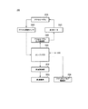
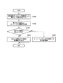
- FIG. 20 is a flowchart showing an example of the switching control process.
- the switching control unit 150 receives an operation on the operator by a vehicle occupant during automatic driving (S100), and compares the operation amount by the received operation with a preset override threshold value 188. (S102), it is determined whether or not the operation amount exceeds a threshold (step S104). In the process of step S104, it may be determined whether or not the state in which the operation amount exceeds the threshold value continues for a reference time or more.
- the switching control unit 150 If the operation amount does not exceed the threshold value, the switching control unit 150 outputs information indicating the comparison result to the HMI control unit 170 (step S106). When the operation amount exceeds the threshold value, the switching control unit 150 performs switching control to manual operation by overriding (step S108).
- FIG. 21 is a flowchart showing an example of the display control process.
- the comparison information acquisition unit 172 acquires information indicating the above-described comparison result from the switching control unit 150 (step S200).
- the interface control unit 174 selects an output unit that can be operated in accordance with the operation mode determined by the mode-specific operation availability determination unit 176 or the like (step S202). In the process of step S202, a preset output unit may be selected.
- the interface control unit 174 generates output information corresponding to the output unit (step S204). For example, when the output unit is the navigation device 50 or the display device 82, character information and an image corresponding to information indicating the comparison result are generated as described above. When the output unit is the speaker 83, sound information corresponding to information indicating the comparison result is generated. Next, the interface control unit 174 outputs the generated output information to the selected output unit (step S206).
- the HMI control unit 170 receives the operation amount related to the speed control or the steering control from the occupant of the host vehicle M received by the HMI 70 and the operation amount for performing the control to switch from the automatic driving to the manual driving.
- the HMI 70 By outputting information indicating the relationship with the threshold value to the output unit of the HMI 70, it is possible to notify information on the degree of operation to the driving operation system from automatic driving to switching to manual driving by override. A sense of security can be given to the vehicle occupant of the vehicle M.
- the present invention can be used in the automobile manufacturing industry.
Landscapes
- Engineering & Computer Science (AREA)
- Automation & Control Theory (AREA)
- Transportation (AREA)
- Mechanical Engineering (AREA)
- Human Computer Interaction (AREA)
- Chemical & Material Sciences (AREA)
- Combustion & Propulsion (AREA)
- Evolutionary Computation (AREA)
- Health & Medical Sciences (AREA)
- Artificial Intelligence (AREA)
- Business, Economics & Management (AREA)
- Game Theory and Decision Science (AREA)
- Medical Informatics (AREA)
- Aviation & Aerospace Engineering (AREA)
- Radar, Positioning & Navigation (AREA)
- Remote Sensing (AREA)
- Physics & Mathematics (AREA)
- General Physics & Mathematics (AREA)
- Control Of Driving Devices And Active Controlling Of Vehicle (AREA)
- Traffic Control Systems (AREA)
Abstract
L'invention concerne un système de commande de véhicule comprenant : une unité de réception d'opération qui reçoit des opérations effectuées par des passagers de véhicule ; une unité de commande de conduite automatique qui effectue automatiquement une commande de vitesse et/ou une commande de direction du véhicule, et qui commute d'une commande automatique à une commande manuelle sur la base d'opérations reçues par l'unité de réception d'opération ; une unité de sortie qui délivre des informations, et une unité de commande d'interface qui délivre, sur l'unité de sortie, des informations indiquant la relation entre une variable de commande concernant la commande de vitesse ou la commande de direction provenant d'un passager de véhicule reçue par l'unité de réception d'opération, et la valeur de seuil pour la variable de commande appliquée par la commande qui commute de la conduite automatique à la commande manuelle au moyen de l'unité de commande de conduite automatique.
Priority Applications (4)
| Application Number | Priority Date | Filing Date | Title |
|---|---|---|---|
| US16/088,520 US20190118831A1 (en) | 2016-03-31 | 2016-03-31 | Vehicle control system, vehicle control method, and vehicle control program |
| JP2018508326A JP6847094B2 (ja) | 2016-03-31 | 2016-03-31 | 車両制御システム、車両制御方法、および車両制御プログラム |
| CN201680083991.1A CN108883775B (zh) | 2016-03-31 | 2016-03-31 | 车辆控制系统、车辆控制方法及存储介质 |
| PCT/JP2016/060863 WO2017168738A1 (fr) | 2016-03-31 | 2016-03-31 | Système de commande de véhicule, procédé de commande de véhicule et programme de commande de véhicule |
Applications Claiming Priority (1)
| Application Number | Priority Date | Filing Date | Title |
|---|---|---|---|
| PCT/JP2016/060863 WO2017168738A1 (fr) | 2016-03-31 | 2016-03-31 | Système de commande de véhicule, procédé de commande de véhicule et programme de commande de véhicule |
Publications (1)
| Publication Number | Publication Date |
|---|---|
| WO2017168738A1 true WO2017168738A1 (fr) | 2017-10-05 |
Family
ID=59962835
Family Applications (1)
| Application Number | Title | Priority Date | Filing Date |
|---|---|---|---|
| PCT/JP2016/060863 WO2017168738A1 (fr) | 2016-03-31 | 2016-03-31 | Système de commande de véhicule, procédé de commande de véhicule et programme de commande de véhicule |
Country Status (4)
| Country | Link |
|---|---|
| US (1) | US20190118831A1 (fr) |
| JP (1) | JP6847094B2 (fr) |
| CN (1) | CN108883775B (fr) |
| WO (1) | WO2017168738A1 (fr) |
Cited By (4)
| Publication number | Priority date | Publication date | Assignee | Title |
|---|---|---|---|---|
| JP2019215069A (ja) * | 2018-06-14 | 2019-12-19 | 本田技研工業株式会社 | 車両の制御装置 |
| JP2020083262A (ja) * | 2018-11-30 | 2020-06-04 | ダイハツ工業株式会社 | 車両制御システム |
| JP2020175799A (ja) * | 2019-04-19 | 2020-10-29 | 株式会社デンソー | 表示装置および表示制御装置 |
| WO2023067879A1 (fr) * | 2021-10-20 | 2023-04-27 | 日立Astemo株式会社 | Dispositif de commande de véhicule, procédé de commande de véhicule et système de commande de véhicule |
Families Citing this family (12)
| Publication number | Priority date | Publication date | Assignee | Title |
|---|---|---|---|---|
| DE102017215844A1 (de) * | 2017-09-08 | 2019-03-14 | Robert Bosch Gmbh | Verfahren zum Betreiben eines Fahrzeugs |
| KR102506932B1 (ko) * | 2018-04-24 | 2023-03-07 | 현대자동차 주식회사 | 차량 쏠림 검사 장치 및 그 방법 |
| JP7163729B2 (ja) * | 2018-11-08 | 2022-11-01 | トヨタ自動車株式会社 | 車両制御装置 |
| WO2020152977A1 (fr) * | 2019-01-21 | 2020-07-30 | 日立オートモティブシステムズ株式会社 | Dispositif de commande de véhicule, procédé de commande de véhicule et système de commande de véhicule |
| JP7135960B2 (ja) * | 2019-03-22 | 2022-09-13 | 株式会社デンソー | 運転引継装置 |
| JP7121681B2 (ja) * | 2019-03-29 | 2022-08-18 | 本田技研工業株式会社 | 車両制御システム |
| JP7293867B2 (ja) * | 2019-05-28 | 2023-06-20 | トヨタ自動車株式会社 | 車両制御システムおよび車両制御インタフェース |
| JP2021017099A (ja) * | 2019-07-18 | 2021-02-15 | 株式会社東海理化電機製作所 | 表示制御システム、表示制御装置およびコンピュータプログラム |
| JP7287291B2 (ja) * | 2020-01-16 | 2023-06-06 | トヨタ自動車株式会社 | 情報処理装置、プログラム、及び、情報処理方法 |
| CN114802245B (zh) * | 2021-01-11 | 2024-04-05 | 广东科学技术职业学院 | 根据交通灯进行并道的方法 |
| US20230174113A1 (en) * | 2021-12-06 | 2023-06-08 | Tusimple, Inc. | Techniques to control an engine for autonomous driving operations |
| JP7509157B2 (ja) * | 2022-01-18 | 2024-07-02 | トヨタ自動車株式会社 | ドライバ監視装置、ドライバ監視用コンピュータプログラム及びドライバ監視方法 |
Citations (4)
| Publication number | Priority date | Publication date | Assignee | Title |
|---|---|---|---|---|
| WO2014097408A1 (fr) * | 2012-12-18 | 2014-06-26 | トヨタ自動車株式会社 | Dispositif d'affichage |
| JP2015153048A (ja) * | 2014-02-12 | 2015-08-24 | 株式会社デンソー | 運転支援装置 |
| WO2015162764A1 (fr) * | 2014-04-24 | 2015-10-29 | 三菱電機株式会社 | Dispositif d'information monté sur un véhicule et procédé de limitation de fonction pour un dispositif d'information monté sur un véhicule |
| JP2015217798A (ja) * | 2014-05-16 | 2015-12-07 | 三菱電機株式会社 | 車載情報表示制御装置 |
Family Cites Families (18)
| Publication number | Priority date | Publication date | Assignee | Title |
|---|---|---|---|---|
| CN1967147B (zh) * | 2005-11-09 | 2011-08-17 | 日产自动车株式会社 | 车辆用驾驶操作辅助装置及具有该装置的车辆 |
| US8744689B2 (en) * | 2007-07-26 | 2014-06-03 | Hitachi, Ltd. | Drive controlling apparatus for a vehicle |
| JP4737238B2 (ja) * | 2008-06-20 | 2011-07-27 | トヨタ自動車株式会社 | 運転支援装置 |
| DE112010003022T5 (de) * | 2009-07-22 | 2012-08-02 | Ntn Corp. | Fahrzeugsteuergerät und darin verwendetes Drehzahlerkennungsgerät |
| JP5407876B2 (ja) * | 2010-01-07 | 2014-02-05 | 三菱自動車工業株式会社 | ハイブリッド車両の表示装置 |
| US8260482B1 (en) * | 2010-04-28 | 2012-09-04 | Google Inc. | User interface for displaying internal state of autonomous driving system |
| JP5152284B2 (ja) * | 2010-09-06 | 2013-02-27 | 株式会社デンソー | 運転者支援装置、および運転者支援システム |
| JP2012091757A (ja) * | 2010-10-29 | 2012-05-17 | Toyota Motor Corp | 表示装置 |
| CN202879398U (zh) * | 2012-09-17 | 2013-04-17 | 周博 | 汽车安全智能驾驶辅助系统 |
| GB2546187B (en) * | 2013-01-28 | 2017-11-01 | Jaguar Land Rover Ltd | Vehicle path prediction and obstacle indication system and method |
| DE102013219917A1 (de) * | 2013-10-01 | 2015-04-02 | Robert Bosch Gmbh | Verfahren und Vorrichtung zur Kollisionsvermeidung für ein Fahrzeug |
| DK2894616T3 (en) * | 2014-01-14 | 2016-02-15 | Kapsch Trafficcom Ag | ONBOARD DEVICE AND PROCEDURE FOR PROVIDING INFORMATION TO A DRIVER |
| JP6323549B2 (ja) * | 2014-04-02 | 2018-05-16 | 日産自動車株式会社 | 車両用情報呈示装置 |
| CN104290745B (zh) * | 2014-10-28 | 2017-02-01 | 奇瑞汽车股份有限公司 | 车辆用半自动驾驶系统的驾驶方法 |
| CN104477167B (zh) * | 2014-11-26 | 2018-04-10 | 浙江大学 | 一种智能驾驶系统及其控制方法 |
| JP6237656B2 (ja) * | 2015-01-19 | 2017-11-29 | トヨタ自動車株式会社 | 車両システム |
| JP6394474B2 (ja) * | 2015-04-10 | 2018-09-26 | トヨタ自動車株式会社 | 自動運転装置 |
| EP3378722B1 (fr) * | 2015-11-19 | 2024-02-21 | Sony Group Corporation | Dispositif d'assistance à la conduite et procédé d'assistance à la conduite, et corps mobile |
-
2016
- 2016-03-31 WO PCT/JP2016/060863 patent/WO2017168738A1/fr active Application Filing
- 2016-03-31 JP JP2018508326A patent/JP6847094B2/ja active Active
- 2016-03-31 CN CN201680083991.1A patent/CN108883775B/zh active Active
- 2016-03-31 US US16/088,520 patent/US20190118831A1/en not_active Abandoned
Patent Citations (4)
| Publication number | Priority date | Publication date | Assignee | Title |
|---|---|---|---|---|
| WO2014097408A1 (fr) * | 2012-12-18 | 2014-06-26 | トヨタ自動車株式会社 | Dispositif d'affichage |
| JP2015153048A (ja) * | 2014-02-12 | 2015-08-24 | 株式会社デンソー | 運転支援装置 |
| WO2015162764A1 (fr) * | 2014-04-24 | 2015-10-29 | 三菱電機株式会社 | Dispositif d'information monté sur un véhicule et procédé de limitation de fonction pour un dispositif d'information monté sur un véhicule |
| JP2015217798A (ja) * | 2014-05-16 | 2015-12-07 | 三菱電機株式会社 | 車載情報表示制御装置 |
Cited By (7)
| Publication number | Priority date | Publication date | Assignee | Title |
|---|---|---|---|---|
| JP2019215069A (ja) * | 2018-06-14 | 2019-12-19 | 本田技研工業株式会社 | 車両の制御装置 |
| JP2020083262A (ja) * | 2018-11-30 | 2020-06-04 | ダイハツ工業株式会社 | 車両制御システム |
| JP7175577B2 (ja) | 2018-11-30 | 2022-11-21 | ダイハツ工業株式会社 | 車両制御システム |
| JP2020175799A (ja) * | 2019-04-19 | 2020-10-29 | 株式会社デンソー | 表示装置および表示制御装置 |
| US11312391B2 (en) | 2019-04-19 | 2022-04-26 | Denso Corporation | Display apparatus and display control apparatus |
| JP7192636B2 (ja) | 2019-04-19 | 2022-12-20 | 株式会社デンソー | 表示装置および表示制御装置 |
| WO2023067879A1 (fr) * | 2021-10-20 | 2023-04-27 | 日立Astemo株式会社 | Dispositif de commande de véhicule, procédé de commande de véhicule et système de commande de véhicule |
Also Published As
| Publication number | Publication date |
|---|---|
| CN108883775A (zh) | 2018-11-23 |
| JPWO2017168738A1 (ja) | 2018-10-04 |
| US20190118831A1 (en) | 2019-04-25 |
| CN108883775B (zh) | 2021-09-07 |
| JP6847094B2 (ja) | 2021-03-24 |
Similar Documents
| Publication | Publication Date | Title |
|---|---|---|
| WO2017168738A1 (fr) | Système de commande de véhicule, procédé de commande de véhicule et programme de commande de véhicule | |
| JP6387548B2 (ja) | 車両制御システム、車両制御方法、および車両制御プログラム | |
| US10337872B2 (en) | Vehicle control system, vehicle control method, and vehicle control program | |
| JP6337382B2 (ja) | 車両制御システム、交通情報共有システム、車両制御方法、および車両制御プログラム | |
| JP6375568B2 (ja) | 車両制御システム、車両制御方法、および車両制御プログラム | |
| JP6745334B2 (ja) | 車両制御システム、車両制御方法、および車両制御プログラム | |
| JP6390035B2 (ja) | 車両制御システム、車両制御方法、および車両制御プログラム | |
| JP6368959B2 (ja) | 車両制御システム、車両制御方法、および車両制御プログラム | |
| JP6540983B2 (ja) | 車両制御システム、車両制御方法、および車両制御プログラム | |
| CN108883776B (zh) | 车辆控制系统、车辆控制方法及存储介质 | |
| WO2017158768A1 (fr) | Système, procédé et programme de commande de véhicule | |
| WO2017168739A1 (fr) | Dispositif de commande de véhicule, procédé de commande de véhicule et programme de commande de véhicule | |
| JP2017165289A (ja) | 車両制御システム、車両制御方法、および車両制御プログラム | |
| JP2017218020A (ja) | 車両制御装置、車両制御方法、および車両制御プログラム | |
| JPWO2017187622A1 (ja) | 車両制御システム、車両制御方法、および車両制御プログラム | |
| JPWO2017179151A1 (ja) | 車両制御システム、車両制御方法、および車両制御プログラム | |
| JPWO2017179193A1 (ja) | 車両制御システム、車両制御方法、および車両制御プログラム | |
| JP2017207885A (ja) | 車両制御システム、車両制御方法、および車両制御プログラム | |
| JPWO2017183077A1 (ja) | 車両制御システム、車両制御方法、および車両制御プログラム | |
| JP6572506B2 (ja) | 車両制御システム | |
| WO2017158764A1 (fr) | Système de commande de véhicule, procédé de commande de véhicule et programme de commande de véhicule | |
| JP2017214035A (ja) | 車両制御システム、車両制御方法、および車両制御プログラム | |
| JP2017214036A (ja) | 車両制御システム、車両制御方法、および車両制御プログラム | |
| JP2017199317A (ja) | 車両制御システム、車両制御方法、および車両制御プログラム | |
| JP2017191551A (ja) | 車両制御システム、車両制御方法、および車両制御プログラム |
Legal Events
| Date | Code | Title | Description |
|---|---|---|---|
| ENP | Entry into the national phase |
Ref document number: 2018508326 Country of ref document: JP Kind code of ref document: A |
|
| NENP | Non-entry into the national phase |
Ref country code: DE |
|
| 121 | Ep: the epo has been informed by wipo that ep was designated in this application |
Ref document number: 16896955 Country of ref document: EP Kind code of ref document: A1 |
|
| 122 | Ep: pct application non-entry in european phase |
Ref document number: 16896955 Country of ref document: EP Kind code of ref document: A1 |