WO2017163682A1 - ロータおよびその製造方法 - Google Patents
ロータおよびその製造方法 Download PDFInfo
- Publication number
- WO2017163682A1 WO2017163682A1 PCT/JP2017/005695 JP2017005695W WO2017163682A1 WO 2017163682 A1 WO2017163682 A1 WO 2017163682A1 JP 2017005695 W JP2017005695 W JP 2017005695W WO 2017163682 A1 WO2017163682 A1 WO 2017163682A1
- Authority
- WO
- WIPO (PCT)
- Prior art keywords
- hub
- outer peripheral
- shaft
- resin
- axial direction
- Prior art date
Links
Images


Classifications
-
- H—ELECTRICITY
- H02—GENERATION; CONVERSION OR DISTRIBUTION OF ELECTRIC POWER
- H02K—DYNAMO-ELECTRIC MACHINES
- H02K1/00—Details of the magnetic circuit
- H02K1/06—Details of the magnetic circuit characterised by the shape, form or construction
- H02K1/22—Rotating parts of the magnetic circuit
- H02K1/27—Rotor cores with permanent magnets
- H02K1/2786—Outer rotors
- H02K1/2787—Outer rotors the magnetisation axis of the magnets being perpendicular to the rotor axis
-
- B—PERFORMING OPERATIONS; TRANSPORTING
- B29—WORKING OF PLASTICS; WORKING OF SUBSTANCES IN A PLASTIC STATE IN GENERAL
- B29C—SHAPING OR JOINING OF PLASTICS; SHAPING OF MATERIAL IN A PLASTIC STATE, NOT OTHERWISE PROVIDED FOR; AFTER-TREATMENT OF THE SHAPED PRODUCTS, e.g. REPAIRING
- B29C45/00—Injection moulding, i.e. forcing the required volume of moulding material through a nozzle into a closed mould; Apparatus therefor
- B29C45/0046—Details relating to the filling pattern or flow paths or flow characteristics of moulding material in the mould cavity
-
- H—ELECTRICITY
- H02—GENERATION; CONVERSION OR DISTRIBUTION OF ELECTRIC POWER
- H02K—DYNAMO-ELECTRIC MACHINES
- H02K1/00—Details of the magnetic circuit
- H02K1/06—Details of the magnetic circuit characterised by the shape, form or construction
- H02K1/22—Rotating parts of the magnetic circuit
- H02K1/27—Rotor cores with permanent magnets
-
- H—ELECTRICITY
- H02—GENERATION; CONVERSION OR DISTRIBUTION OF ELECTRIC POWER
- H02K—DYNAMO-ELECTRIC MACHINES
- H02K1/00—Details of the magnetic circuit
- H02K1/06—Details of the magnetic circuit characterised by the shape, form or construction
- H02K1/22—Rotating parts of the magnetic circuit
- H02K1/28—Means for mounting or fastening rotating magnetic parts on to, or to, the rotor structures
-
- H—ELECTRICITY
- H02—GENERATION; CONVERSION OR DISTRIBUTION OF ELECTRIC POWER
- H02K—DYNAMO-ELECTRIC MACHINES
- H02K15/00—Methods or apparatus specially adapted for manufacturing, assembling, maintaining or repairing of dynamo-electric machines
- H02K15/02—Methods or apparatus specially adapted for manufacturing, assembling, maintaining or repairing of dynamo-electric machines of stator or rotor bodies
- H02K15/03—Methods or apparatus specially adapted for manufacturing, assembling, maintaining or repairing of dynamo-electric machines of stator or rotor bodies having permanent magnets
-
- B—PERFORMING OPERATIONS; TRANSPORTING
- B29—WORKING OF PLASTICS; WORKING OF SUBSTANCES IN A PLASTIC STATE IN GENERAL
- B29C—SHAPING OR JOINING OF PLASTICS; SHAPING OF MATERIAL IN A PLASTIC STATE, NOT OTHERWISE PROVIDED FOR; AFTER-TREATMENT OF THE SHAPED PRODUCTS, e.g. REPAIRING
- B29C45/00—Injection moulding, i.e. forcing the required volume of moulding material through a nozzle into a closed mould; Apparatus therefor
- B29C2045/0093—Injection moulding, i.e. forcing the required volume of moulding material through a nozzle into a closed mould; Apparatus therefor of articles provided with an attaching element
-
- B—PERFORMING OPERATIONS; TRANSPORTING
- B29—WORKING OF PLASTICS; WORKING OF SUBSTANCES IN A PLASTIC STATE IN GENERAL
- B29L—INDEXING SCHEME ASSOCIATED WITH SUBCLASS B29C, RELATING TO PARTICULAR ARTICLES
- B29L2031/00—Other particular articles
- B29L2031/748—Machines or parts thereof not otherwise provided for
- B29L2031/7498—Rotors
-
- H—ELECTRICITY
- H02—GENERATION; CONVERSION OR DISTRIBUTION OF ELECTRIC POWER
- H02K—DYNAMO-ELECTRIC MACHINES
- H02K21/00—Synchronous motors having permanent magnets; Synchronous generators having permanent magnets
- H02K21/12—Synchronous motors having permanent magnets; Synchronous generators having permanent magnets with stationary armatures and rotating magnets
- H02K21/22—Synchronous motors having permanent magnets; Synchronous generators having permanent magnets with stationary armatures and rotating magnets with magnets rotating around the armatures, e.g. flywheel magnetos
Definitions
- the present invention relates to, for example, a rotor used in a motor provided in a compressor, a blower, and the like, and a method for manufacturing the same.
- a cylindrical connecting part As a rotor, a cylindrical connecting part, a radial rib extending radially outward from the connecting part, and an outer peripheral part surrounding the connecting part connected to the radially outer end of the rib are provided.
- Patent Document 1 Japanese Patent Laid-Open No. 2001-320844 (Patent Document 1)).
- the inner peripheral surface of the connecting part is fixed to the outer peripheral surface of the shaft, and the central axis of the connecting part and the central axis of the shaft coincide with each other.
- the connecting component is integrally formed with the rib and the outer peripheral portion using a thermoplastic resin.
- An annular magnetic pole portion made of a plastic magnet is fixed to the outer peripheral surface of the outer peripheral portion.
- This magnetic pole portion is formed using a resin that is harder than the thermoplastic resin and contains a magnetic material (hereinafter referred to as “plastic magnet material resin”).
- a plastic magnet material resin is formed in a ring space for forming the magnetic pole part in the mold from a plurality of resin injection gates provided at predetermined intervals in the circumferential direction in the mold. Is generally injected.
- the connecting parts, the ribs, and the outer peripheral portion are also formed of a plastic magnet material resin to simplify the manufacturing process, the following problems may occur.
- plastic magnet material resin is placed in the space in the mold with a part of the shaft arranged in the space in the mold. Fill. At this time, the plastic magnet material resin flows from the annular space for forming the magnetic pole portion into the cylindrical space for forming the connecting part through the radial space for forming the rib.
- an object of the present invention is to provide a rotor that can improve the fixing strength between the hub and the shaft even if the hub made of resin is fixed to the shaft, and a manufacturing method thereof.
- the rotor of the present invention is: A shaft, A hub made of resin and fixed to one end of the shaft in the axial direction, covering one end surface of the shaft in the axial direction; A plurality of connecting portions extending radially outward from the hub and made of resin; An outer peripheral portion provided on the outer side in the radial direction of the hub, and connected to the hub via the connecting portion; One end face of the hub in the axial direction has a resin injection gate mark.
- the connecting portion is inclined to form an acute angle with the axial direction.
- the molten resin can flow smoothly in the space for forming the connecting portion when the connecting portion is formed.
- the hub, the connecting portion, and the outer peripheral portion are made of a plastic magnet.
- the hub, the connecting portion, and the outer peripheral portion are made of plastic magnets, the hub, the connecting portion, and the outer peripheral portion can be easily formed integrally with the shaft, and the magnetic pole can be easily formed on the outer peripheral portion. You can have it.
- the method of manufacturing the rotor of the present invention is as follows: A shaft, a hub fixed to one end of the shaft in the axial direction, covering one end surface of the shaft in the axial direction, made of resin, and extending radially outward from the hub in a radial direction; A rotor manufacturing method for manufacturing a rotor comprising a plurality of connecting portions and an outer peripheral portion provided on the outer side in the radial direction of the hub and connected to the hub via the connecting portion, A hub forming space for forming the hub, a connecting portion forming space for forming the connecting portion, and an outer peripheral portion forming space for forming the outer peripheral portion using a plurality of molds, Defining in a communicating state and disposing one end surface in the axial direction of the shaft in the hub forming space; In the mold, a molten resin is injected into the hub forming space from a resin injection gate facing one axial end surface of the shaft, and the hub forming space is passed through the connecting portion forming space to the outer
- the weld line of the hub can be reduced.
- the fixing strength of can be improved.
- the weld line of the hub can be reduced by having a resin injection gate mark on one end surface in the axial direction of the hub, the fixing strength between the hub and the shaft can be improved.
- the method of manufacturing a rotor according to the present invention is such that molten resin is injected into a hub forming space from a resin injection gate facing one axial end surface of a shaft in a mold, and the outer peripheral portion is connected from the hub forming space through a connecting portion forming space. Since molten resin is allowed to flow in the forming space, the weld line of the hub can be reduced. Therefore, the fixing strength between the hub and the shaft can be improved.
- FIG. 5 is a schematic sectional view taken along line VV in FIG. 2. It is a schematic cross section for demonstrating one process of the manufacturing method of the said rotor.
- FIG. 3 is a schematic cross-sectional view for explaining a process following the process of FIG. 2. It is a schematic cross section for demonstrating one process of the manufacturing method of a comparative example. It is a schematic cross section of the rotor of the second embodiment of the present invention.
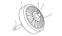
- FIG. 1 is a schematic upper perspective view of the rotor according to the first embodiment of the present invention as viewed obliquely from above.
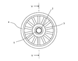
- FIG. 2 is a schematic top view as seen from above the rotor.
- FIG. 3 is a schematic side view of the rotor as viewed from the side.
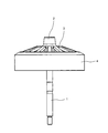
- FIG. 4 is a schematic lower perspective view of the rotor as viewed from below.
- FIG. 5 is a schematic cross-sectional view as seen from the line VV in FIG.
- the rotor includes a shaft 1, a hub 2 fixed to one end of the shaft 1 in the axial direction, and radially extending from the hub 2 outward in the radial direction. And a plurality of connecting portions 3 and an outer peripheral portion 4 connected to the hub 2 via the connecting portions 3.
- the shaft is made of metal, for example, and is integrated with the hub 2, the connecting portion 3, and the outer peripheral portion 4. Thereby, when the outer peripheral portion 4 rotates around the shaft 1, the shaft 1 also rotates integrally with the outer peripheral portion 4.
- the hub 2 is made of a plastic magnet as an example of resin, and covers one end surface of the shaft 1 in the axial direction. There is a circular resin injection gate mark 5 on one end surface of the hub 2 in the axial direction. One end surface of the hub 2 in the axial direction has a molecular orientation due to resin flow from the radially inner side to the radially outer side.
- the plurality of connecting portions 3 are provided at substantially equal intervals in the circumferential direction and are made of a plastic magnet. Each of the plurality of connecting portions 3 is inclined so as to form an acute angle with respect to the axial direction. In other words, each connecting portion 3 has a radially outer end portion on the other end portion in the axial direction of the shaft 1 (an end portion not covered with the hub 2) side than a radially inner end portion. Inclined to be located at. Moreover, between the connection parts 3 is a space penetrating in the axial direction.
- the outer peripheral portion 4 is also made of a plastic magnet, like the hub 2 and the connecting portion 3.
- the outer peripheral portion 4 is formed in a cylindrical shape and is disposed around the hub 2. Further, the outer peripheral portion 4 is magnetized so that N poles and S poles are alternately arranged in the circumferential direction.
- molten magnetic resin molten resin containing magnetic powder or the like
- a molten magnetic resin having a constant temperature is injected into each part of the space for forming the hub 2. Accordingly, since the molten magnetic resin can be contracted substantially uniformly in the space, the strength variation of each part of the hub 2 can be reduced.
- the connecting portion 3 is inclined so as to form an acute angle with the axial direction, the molten magnetic resin can be smoothly flowed in the space for forming the connecting portion 3 when the connecting portion 3 is formed.
- the hub 2, the connecting portion 3 and the outer peripheral portion 4 are made of plastic magnets, the hub 2, the connecting portion 3 and the outer peripheral portion 4 can be easily formed integrally, and the outer peripheral portion 4 is provided with a magnetic pole. It is easy.
- a plurality of molds 11 to 15 are combined with each other.
- the hub forming space 21 for forming the hub 2 the connecting portion forming space 22 for forming the connecting portion 3
- the outer peripheral portion forming space 23 for forming the outer peripheral portion 4 communicate with each other.
- one end face of the shaft 1 in the axial direction is disposed in the hub forming space 21.
- molten magnetic resin is injected into the hub forming space 21 from the resin injection gate 15a facing the one end surface in the axial direction of the hub 2 in the mold 15, and the outer periphery from the hub forming space through the connecting portion forming space 22 A molten magnetic resin is poured into the part forming space 23.
- the weld line of the hub 2 can be reduced.
- the fixing strength between the shaft 1 and the hub 2 can be improved.
- the connecting portion forming space 22 is inclined so as to form an acute angle with respect to the axial direction, the molten magnetic resin is smoothly supplied from the hub forming space 21 side to the outer peripheral portion forming space 23 side of the connecting portion forming space 22. It can flow.
- an outer peripheral portion forming space is formed from a plurality of resin injection gates 115 a provided at predetermined intervals in the circumferential direction in the mold 115. 23 is injected with molten magnetic resin. As a result, the molten magnetic resin flows from the outer peripheral portion forming space 23 into the hub forming space 21 via the connecting portion forming space 22, so that the weld line of the hub 2 increases.
- the connecting portion 3 is formed to form an acute angle with the axial direction, but may be formed to be orthogonal to the axial direction.
- the circumferential interval between the connecting portions 3 is substantially the same, but may be different.
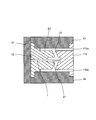
- FIG. 9 is a schematic cross-sectional view when the rotor according to the second embodiment of the present invention is cut along a plane parallel to the axial direction.
- the rotor includes a hub 202, a connecting portion 203, and an outer peripheral portion 204, which are different from those of the hub 2, the connecting portion 3, and the outer peripheral portion 4 of the first embodiment. More specifically, the hub 202, the connecting portion 203, and the outer peripheral portion 204 are integrally formed of a thermoplastic resin such as polyethylene or polypropylene, for example.
- annular magnet 207 is fixed by press-fitting to the outer peripheral surface of the outer peripheral portion 204.
- the annular magnet 207 is a sintered magnet obtained by performing a sintering process, a heat treatment process, a magnetizing process, and the like. Also in the annular magnet 207, the N poles and the S poles are alternately arranged in the circumferential direction as in the outer peripheral portion 4 of the first embodiment.
- the hub 202, the connecting portion 203 and the outer peripheral portion 204 are also formed by the same manufacturing method as the hub 2, the connecting portion 3 and the outer peripheral portion 4 of the first embodiment.
- a circular resin injection gate mark remains on one end surface in the axial direction.
- a metal ring made of an iron plate, a steel plate, or the like is interposed between the outer peripheral surface of the outer peripheral portion 204 and the annular magnet 207.
- the rotor having the above-described configuration has the same effects as the first embodiment, and can be retrofitted with the annular magnet 207, so that it is highly versatile.
- the annular magnet 207 is fixed to the outer peripheral surface of the outer peripheral portion 204 by press fitting.
- a plastic magnet may be fixed to the outer peripheral surface of the outer peripheral portion 204 by two-color molding.
- an iron plate or a steel plate is interposed between the outer peripheral surface of the outer peripheral portion 204 and the annular magnet 207, but such an iron plate or steel plate may not be interposed.
- the present invention can be applied to various rotors such as brushless motors and stepping motors and manufacturing methods thereof.
Landscapes
- Engineering & Computer Science (AREA)
- Power Engineering (AREA)
- Manufacturing & Machinery (AREA)
- Mechanical Engineering (AREA)
- Permanent Field Magnets Of Synchronous Machinery (AREA)
- Manufacture Of Motors, Generators (AREA)
- Moulds For Moulding Plastics Or The Like (AREA)
- Permanent Magnet Type Synchronous Machine (AREA)
Abstract
Description
シャフトと、
上記シャフトの軸方向の一端部に固定されて、上記シャフトの軸方向の一端面を覆って樹脂からなるハブと、
上記ハブから径方向外側に向かって放射状に延在し、樹脂からなる複数の連結部と、
上記ハブの径方向外側に設けられて、上記ハブに上記連結部を介して接続された外周部と
を備え、
上記ハブの軸方向の一端面には樹脂注入ゲート痕があることを特徴としている。
上記連結部は軸方向と鋭角を成すように傾斜する。
上記ハブ、連結部および外周部は、プラスチックマグネットからなる。
シャフトと、上記シャフトの軸方向の一端部に固定されて、上記シャフトの軸方向の一端面を覆って樹脂からなるハブと、上記ハブから径方向外側に向かって放射状に延在し、樹脂からなる複数の連結部と、上記ハブの径方向外側に設けられて、上記ハブに上記連結部を介して接続された外周部とを備えるロータを製造するロータの製造方法であって、
複数の金型を用いて、上記ハブを形成するためのハブ形成空間と、上記連結部を形成するための連結部形成空間と、上記外周部を形成するための外周部形成空間とを、互いに連通する状態で画定すると共に、上記ハブ形成空間に上記シャフトの軸方向の一端面を配置する工程と、
上記金型において上記シャフトの軸方向の一端面に対向する樹脂注入ゲートから、上記ハブ形成空間に溶融樹脂を注入し、上記ハブ形成空間から上記連結部形成空間を介して上記外周部形成空間に溶融樹脂を流した後、上記ハブ形成空間、連結部形成空間および外周部形成空間のそれぞれの空間内の溶融樹脂を硬化させることにより、上記ハブ、連結部および外周部を形成する工程と
を備えることを特徴としている。
図1は、この発明の第1実施形態のロータを斜め上方から見たときの概略上方斜視図である。また、図2は、上記ロータの上方から見たときの概略上面図である。また、図3は、上記ロータを側方から見たときの概略側面図である。また、図4は、上記ロータを下方から見たときの概略下方斜視図である。また、図5は、図2のV-V線から見たときの概略断面図である。
図9は、この発明の第2実施形態のロータを軸方向に平行な面で切ったときの模式断面図である。
2,202 ハブ
3,203 連結部
4,204 外周部
5 樹脂注入ゲート痕
11~15 金型
15a 樹脂注入ゲート
21 ハブ形成空間
22 連結部形成空間
23 外周部形成空間
Claims (4)
- シャフト(1)と、
上記シャフト(1)の軸方向の一端部に固定されて、上記シャフト(1)の軸方向の一端面を覆って樹脂からなるハブ(2,202)と、
上記ハブ(2,202)から径方向外側に向かって放射状に延在し、樹脂からなる複数の連結部(3,203)と、
上記ハブ(2,202)の径方向外側に設けられて、上記ハブ(2,202)に上記連結部(3,203)を介して接続された外周部(4,204)と
を備え、
上記ハブ(2,202)の軸方向の一端面には樹脂注入ゲート痕(5)があることを特徴とするロータ。 - 請求項1に記載のロータにおいて、
上記連結部(3,203)は軸方向と鋭角を成すように傾斜することを特徴とするロータ。 - 請求項1または2に記載のロータにおいて、
上記ハブ(2)、連結部(3)および外周部(4)は、プラスチックマグネットからなることを特徴とするロータ。 - シャフト(1)と、上記シャフト(1)の軸方向の一端部に固定されて、上記シャフト(1)の軸方向の一端面を覆って樹脂からなるハブ(2,202)と、上記ハブ(2,202)から径方向外側に向かって放射状に延在し、樹脂からなる複数の連結部(3,203)と、上記ハブ(2,202)の径方向外側に設けられて、上記ハブ(2,202)に上記連結部(3,203)を介して接続された外周部(4,204)とを備えるロータを製造するロータの製造方法であって、
複数の金型(11~15)を用いて、上記ハブ(2,202)を形成するためのハブ形成空間(21)と、上記連結部(3,203)を形成するための連結部形成空間(22)と、上記外周部(4,204)を形成するための外周部形成空間(23)とを、互いに連通する状態で画定すると共に、上記ハブ形成空間(21)に上記シャフト(1)の軸方向の一端面を配置する工程と、
上記金型(15)において上記シャフト(1)の軸方向の一端面に対向する樹脂注入ゲート(15a)から、上記ハブ形成空間(21)に溶融樹脂を注入し、上記ハブ形成空間(21)から上記連結部形成空間(22)を介して上記外周部形成空間(23)に溶融樹脂を流した後、上記ハブ形成空間(21)、連結部形成空間(22)および外周部形成空間(23)のそれぞれの空間内の溶融樹脂を硬化させることにより、上記ハブ(2,202)、連結部(3,203)および外周部(4,204)を形成する工程と
を備えることを特徴とするロータの製造方法。
Priority Applications (5)
| Application Number | Priority Date | Filing Date | Title |
|---|---|---|---|
| MYPI2018001575A MY186468A (en) | 2016-03-25 | 2017-02-16 | Rotor and production method therefor |
| EP17769729.9A EP3435522A4 (en) | 2016-03-25 | 2017-02-16 | ROTOR AND MANUFACTURING METHOD THEREFOR |
| CN201780014287.5A CN108713283B (zh) | 2016-03-25 | 2017-02-16 | 转子及其制造方法 |
| AU2017237623A AU2017237623B2 (en) | 2016-03-25 | 2017-02-16 | Rotor and production method therefor |
| US16/087,497 US20190123625A1 (en) | 2016-03-25 | 2017-02-16 | Rotor and production method therefor |
Applications Claiming Priority (2)
| Application Number | Priority Date | Filing Date | Title |
|---|---|---|---|
| JP2016062565A JP6160730B1 (ja) | 2016-03-25 | 2016-03-25 | ロータおよびその製造方法 |
| JP2016-062565 | 2016-03-25 |
Publications (1)
| Publication Number | Publication Date |
|---|---|
| WO2017163682A1 true WO2017163682A1 (ja) | 2017-09-28 |
Family
ID=59308861
Family Applications (1)
| Application Number | Title | Priority Date | Filing Date |
|---|---|---|---|
| PCT/JP2017/005695 WO2017163682A1 (ja) | 2016-03-25 | 2017-02-16 | ロータおよびその製造方法 |
Country Status (7)
| Country | Link |
|---|---|
| US (1) | US20190123625A1 (ja) |
| EP (1) | EP3435522A4 (ja) |
| JP (1) | JP6160730B1 (ja) |
| CN (1) | CN108713283B (ja) |
| AU (1) | AU2017237623B2 (ja) |
| MY (1) | MY186468A (ja) |
| WO (1) | WO2017163682A1 (ja) |
Citations (3)
| Publication number | Priority date | Publication date | Assignee | Title |
|---|---|---|---|---|
| JPS53147911A (en) * | 1977-05-30 | 1978-12-23 | Omron Tateisi Electronics Co | Preparing magnetic rotor |
| JPS60152256A (ja) * | 1984-01-18 | 1985-08-10 | Atsugi Motor Parts Co Ltd | モ−タの製造方法 |
| JP2001320844A (ja) * | 2000-05-09 | 2001-11-16 | Mitsubishi Electric Corp | プラスチックマグネットロータ及び空気調和機 |
Family Cites Families (13)
| Publication number | Priority date | Publication date | Assignee | Title |
|---|---|---|---|---|
| JPS59136053A (ja) * | 1983-01-21 | 1984-08-04 | Daido Steel Co Ltd | 回転電機用ロ−タの製造方法およびその装置 |
| JPH04217834A (ja) * | 1990-12-19 | 1992-08-07 | Yamauchi Corp | プラスチック・マグネット付きロータ |
| US20060273677A1 (en) * | 2005-06-07 | 2006-12-07 | Sunonwealth Electric Machine Industry Co., Ltd. | Rotor for motor |
| JP2008004143A (ja) * | 2006-06-20 | 2008-01-10 | Fujifilm Corp | リール及び記録テープカートリッジ |
| CN101442228A (zh) * | 2007-11-20 | 2009-05-27 | 建凖电机工业股份有限公司 | 一种马达转子 |
| JP2009211779A (ja) * | 2008-03-05 | 2009-09-17 | Fujifilm Corp | リール及び記録テープカートリッジ |
| DE202008004881U1 (de) * | 2008-04-08 | 2008-07-31 | Industrialpartners Gmbh | Bürstenloser Elektromotor |
| US20110050027A1 (en) * | 2009-08-28 | 2011-03-03 | Alex Horng | Motor Rotor |
| JP2011172371A (ja) * | 2010-02-18 | 2011-09-01 | Nippon Densan Corp | モータ、ディスク駆動装置、およびモータの製造方法 |
| WO2011131251A1 (de) * | 2010-04-19 | 2011-10-27 | Pierburg Pump Technology Gmbh | Elektrische kfz-kühlmittelpumpe |
| JP5965712B2 (ja) * | 2012-04-25 | 2016-08-10 | 株式会社不二工機 | 電動弁用駆動モータのステータ |
| CN103095003A (zh) * | 2012-12-14 | 2013-05-08 | 泰信电机(苏州)有限公司 | 洗衣机变频电机用注塑磁圆形转子装置及制备方法 |
| CN105262265B (zh) * | 2015-11-13 | 2018-08-07 | 汕头市杰泰电子科技有限公司 | 一种无刷直流电机外转子机壳及其制作工艺 |
-
2016
- 2016-03-25 JP JP2016062565A patent/JP6160730B1/ja active Active
-
2017
- 2017-02-16 EP EP17769729.9A patent/EP3435522A4/en active Pending
- 2017-02-16 US US16/087,497 patent/US20190123625A1/en not_active Abandoned
- 2017-02-16 CN CN201780014287.5A patent/CN108713283B/zh active Active
- 2017-02-16 AU AU2017237623A patent/AU2017237623B2/en active Active
- 2017-02-16 WO PCT/JP2017/005695 patent/WO2017163682A1/ja active Application Filing
- 2017-02-16 MY MYPI2018001575A patent/MY186468A/en unknown
Patent Citations (3)
| Publication number | Priority date | Publication date | Assignee | Title |
|---|---|---|---|---|
| JPS53147911A (en) * | 1977-05-30 | 1978-12-23 | Omron Tateisi Electronics Co | Preparing magnetic rotor |
| JPS60152256A (ja) * | 1984-01-18 | 1985-08-10 | Atsugi Motor Parts Co Ltd | モ−タの製造方法 |
| JP2001320844A (ja) * | 2000-05-09 | 2001-11-16 | Mitsubishi Electric Corp | プラスチックマグネットロータ及び空気調和機 |
Non-Patent Citations (1)
| Title |
|---|
| See also references of EP3435522A4 * |
Also Published As
| Publication number | Publication date |
|---|---|
| US20190123625A1 (en) | 2019-04-25 |
| EP3435522A1 (en) | 2019-01-30 |
| JP6160730B1 (ja) | 2017-07-12 |
| AU2017237623B2 (en) | 2019-08-22 |
| MY186468A (en) | 2021-07-22 |
| JP2017175882A (ja) | 2017-09-28 |
| EP3435522A4 (en) | 2019-11-13 |
| CN108713283B (zh) | 2021-05-11 |
| AU2017237623A1 (en) | 2018-10-11 |
| CN108713283A (zh) | 2018-10-26 |
Similar Documents
| Publication | Publication Date | Title |
|---|---|---|
| KR101730898B1 (ko) | 로터 유닛, 회전형 전기 기기 및 로터 유닛을 제조하는 방법 | |
| WO2015036780A3 (en) | Stator-plate overmoulding | |
| US10116193B2 (en) | Interior permanent magnet rotor and method and apparatus for manufacturing the same | |
| JP6026000B2 (ja) | 電動機の回転子、電動機、及び空気調和機 | |
| EP3395532B1 (en) | Bonded-magnet injection molding device and bonded-magnet injection molding method | |
| JP5501660B2 (ja) | 電動モータ及びそのロータ | |
| CN104428980A (zh) | 线圈、旋转电机及线圈的制造方法 | |
| JP6531168B2 (ja) | 磁石埋め込み型コアの樹脂充填装置および樹脂充填方法 | |
| JP6076288B2 (ja) | ロータ製造方法、ロータおよびモータ | |
| CN110118190B (zh) | 泵轮、用于制造泵轮的方法和带有泵轮的泵 | |
| WO2017163682A1 (ja) | ロータおよびその製造方法 | |
| JP6861967B2 (ja) | 電動ポンプ用ロータの製造方法 | |
| JP6692870B2 (ja) | アウターロータ型電動機用ロータ | |
| JP5917333B2 (ja) | 回転電機の回転子 | |
| KR101668660B1 (ko) | 모터의 로터 | |
| US20190238033A1 (en) | Rotor and rotary electric machine | |
| US20190157951A1 (en) | Rotor, electric motor, air conditioner, and method for manufacturing rotor | |
| JP6537713B2 (ja) | 電動機及び空気調和機 | |
| JP3645426B2 (ja) | 整流子の成形方法 | |
| JP7148566B2 (ja) | モータの回転子及びその製造方法 | |
| EP2747248B1 (en) | Magnetic rotor unit | |
| KR20230164967A (ko) | 외전형 모터의 로터바디 및 그의 제조방법 | |
| WO2017187581A1 (ja) | 電動機及び空気調和機 |
Legal Events
| Date | Code | Title | Description |
|---|---|---|---|
| NENP | Non-entry into the national phase |
Ref country code: DE |
|
| ENP | Entry into the national phase |
Ref document number: 2017237623 Country of ref document: AU Date of ref document: 20170216 Kind code of ref document: A |
|
| WWE | Wipo information: entry into national phase |
Ref document number: 2017769729 Country of ref document: EP |
|
| ENP | Entry into the national phase |
Ref document number: 2017769729 Country of ref document: EP Effective date: 20181025 |
|
| 121 | Ep: the epo has been informed by wipo that ep was designated in this application |
Ref document number: 17769729 Country of ref document: EP Kind code of ref document: A1 |