WO2017159257A1 - 物体検知装置 - Google Patents
物体検知装置 Download PDFInfo
- Publication number
- WO2017159257A1 WO2017159257A1 PCT/JP2017/006661 JP2017006661W WO2017159257A1 WO 2017159257 A1 WO2017159257 A1 WO 2017159257A1 JP 2017006661 W JP2017006661 W JP 2017006661W WO 2017159257 A1 WO2017159257 A1 WO 2017159257A1
- Authority
- WO
- WIPO (PCT)
- Prior art keywords
- switch
- piezoelectric vibrator
- coil
- resistor
- detection device
- Prior art date
Links
Images


Classifications
-
- G—PHYSICS
- G01—MEASURING; TESTING
- G01S—RADIO DIRECTION-FINDING; RADIO NAVIGATION; DETERMINING DISTANCE OR VELOCITY BY USE OF RADIO WAVES; LOCATING OR PRESENCE-DETECTING BY USE OF THE REFLECTION OR RERADIATION OF RADIO WAVES; ANALOGOUS ARRANGEMENTS USING OTHER WAVES
- G01S15/00—Systems using the reflection or reradiation of acoustic waves, e.g. sonar systems
- G01S15/88—Sonar systems specially adapted for specific applications
- G01S15/93—Sonar systems specially adapted for specific applications for anti-collision purposes
- G01S15/931—Sonar systems specially adapted for specific applications for anti-collision purposes of land vehicles
-
- G—PHYSICS
- G01—MEASURING; TESTING
- G01S—RADIO DIRECTION-FINDING; RADIO NAVIGATION; DETERMINING DISTANCE OR VELOCITY BY USE OF RADIO WAVES; LOCATING OR PRESENCE-DETECTING BY USE OF THE REFLECTION OR RERADIATION OF RADIO WAVES; ANALOGOUS ARRANGEMENTS USING OTHER WAVES
- G01S7/00—Details of systems according to groups G01S13/00, G01S15/00, G01S17/00
- G01S7/52—Details of systems according to groups G01S13/00, G01S15/00, G01S17/00 of systems according to group G01S15/00
- G01S7/521—Constructional features
-
- G—PHYSICS
- G01—MEASURING; TESTING
- G01S—RADIO DIRECTION-FINDING; RADIO NAVIGATION; DETERMINING DISTANCE OR VELOCITY BY USE OF RADIO WAVES; LOCATING OR PRESENCE-DETECTING BY USE OF THE REFLECTION OR RERADIATION OF RADIO WAVES; ANALOGOUS ARRANGEMENTS USING OTHER WAVES
- G01S15/00—Systems using the reflection or reradiation of acoustic waves, e.g. sonar systems
- G01S15/02—Systems using the reflection or reradiation of acoustic waves, e.g. sonar systems using reflection of acoustic waves
- G01S15/04—Systems determining presence of a target
-
- G—PHYSICS
- G01—MEASURING; TESTING
- G01S—RADIO DIRECTION-FINDING; RADIO NAVIGATION; DETERMINING DISTANCE OR VELOCITY BY USE OF RADIO WAVES; LOCATING OR PRESENCE-DETECTING BY USE OF THE REFLECTION OR RERADIATION OF RADIO WAVES; ANALOGOUS ARRANGEMENTS USING OTHER WAVES
- G01S15/00—Systems using the reflection or reradiation of acoustic waves, e.g. sonar systems
- G01S15/88—Sonar systems specially adapted for specific applications
- G01S15/93—Sonar systems specially adapted for specific applications for anti-collision purposes
-
- G—PHYSICS
- G01—MEASURING; TESTING
- G01S—RADIO DIRECTION-FINDING; RADIO NAVIGATION; DETERMINING DISTANCE OR VELOCITY BY USE OF RADIO WAVES; LOCATING OR PRESENCE-DETECTING BY USE OF THE REFLECTION OR RERADIATION OF RADIO WAVES; ANALOGOUS ARRANGEMENTS USING OTHER WAVES
- G01S7/00—Details of systems according to groups G01S13/00, G01S15/00, G01S17/00
- G01S7/52—Details of systems according to groups G01S13/00, G01S15/00, G01S17/00 of systems according to group G01S15/00
- G01S7/523—Details of pulse systems
- G01S7/524—Transmitters
-
- G—PHYSICS
- G01—MEASURING; TESTING
- G01S—RADIO DIRECTION-FINDING; RADIO NAVIGATION; DETERMINING DISTANCE OR VELOCITY BY USE OF RADIO WAVES; LOCATING OR PRESENCE-DETECTING BY USE OF THE REFLECTION OR RERADIATION OF RADIO WAVES; ANALOGOUS ARRANGEMENTS USING OTHER WAVES
- G01S7/00—Details of systems according to groups G01S13/00, G01S15/00, G01S17/00
- G01S7/52—Details of systems according to groups G01S13/00, G01S15/00, G01S17/00 of systems according to group G01S15/00
- G01S7/523—Details of pulse systems
- G01S7/526—Receivers
Definitions
- the present disclosure relates to an object detection device that transmits a survey wave and receives a reflected wave reflected by an object.
- an object detection device that transmits a search wave, receives a reflected wave reflected by an object, and detects the distance to the object, reverberation occurs when the search wave is transmitted. Since the energy of the reverberation is generally significantly larger than the energy of the reflected wave, it is difficult to detect the reflected wave even if the reflected wave is received during the time when the reverberation occurs (reverberation time).
- the present disclosure has been made to solve the above-described problems, and a main object thereof is to provide an object detection device capable of improving the object detection performance.
- the present disclosure is an ultrasonic sensor that drives a piezoelectric vibrator, transmits an exploration wave, and receives a reflected wave reflected by an object, and supplies the piezoelectric vibrator and driving power for driving the piezoelectric vibrator.
- a driving circuit ; and a resistance unit connected in parallel with the piezoelectric vibrator and having a variable resistance value.
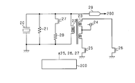
- FIG. 1 is a configuration diagram of an ultrasonic sensor according to the first embodiment.
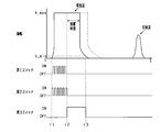
- FIG. 2 is a time chart showing processing executed by the control unit in the first embodiment.
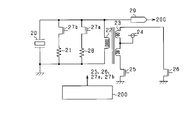
- FIG. 3 is a configuration diagram of an ultrasonic sensor according to the second embodiment.
- FIG. 4 is a configuration diagram of an ultrasonic sensor according to the fifth embodiment.
- 5A is a time chart in the long-distance mode
- FIG. 5B is a time chart in the short-distance mode
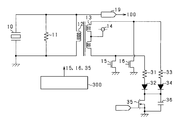
- FIG. 6 is a configuration diagram of an ultrasonic sensor according to the sixth embodiment.
- FIG. 7 is a configuration diagram of an ultrasonic sensor according to the seventh embodiment.
- FIG. 8 is a time chart showing processing executed by the control unit in the seventh embodiment.
- the object detection apparatus is an ultrasonic sensor and is mounted on a moving body such as a vehicle.
- the ultrasonic sensor transmits ultrasonic waves to the surroundings of the moving body, receives the reflected waves reflected by the objects existing in the surroundings, and measures the time from transmission to reception, thereby measuring the distance between the moving body and the objects.
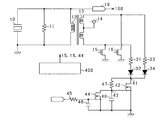
- FIG. 1 is a circuit diagram of an ultrasonic sensor according to the present embodiment.
- the ultrasonic sensor transmits ultrasonic waves by applying a voltage to the piezoelectric vibrator 10 and converts the energy of the reflected wave received by the piezoelectric vibrator 10 into a voltage.
- a first resistor 11 and a first coil 12 are connected to the piezoelectric vibrator 10 in parallel.
- the first coil 12 forms a transformer with the second coil 13 that is magnetically coupled.
- the second coil 13 includes a center tap, and a power source 14 is connected to the center tap.
- the voltage of the power supply 14 is 12V, for example.
- the first end of the second coil 13 is grounded via the first switch 15, and the second end of the second coil 13 is grounded via the second switch 16.
- the second coil 13, the first switch 15, and the second switch 16 constitute a drive circuit for the piezoelectric vibrator 10.
- the first end and the second end of the second coil 13 are connected by a series connection body of the third switch 17 and the second resistor 18.
- the voltage on the first coil 12 side is input to the control unit 100 via the amplifier 19, and the control unit 100 transmits a control signal to the first switch 15, the second switch 16, and the third switch 17.
- the control unit 100 is a computer that includes a CPU, ROM, RAM, I / O, and the like.
- the control unit 100 transmits an exploration wave, and controls until a predetermined time elapses from the transmission as one control cycle.
- the control unit 100 performs drive control in which the first switch 15 and the second switch 16 are alternately turned on to supply drive power. By doing so, the piezoelectric vibrator 10 is driven by being applied with voltages in the forward and reverse directions alternately.
- the reflected wave is received by the piezoelectric vibrator 10
- both the first switch 15 and the second switch 16 are turned off. By doing so, power is not supplied from the second coil 13 side to the first coil 12 side, and the piezoelectric vibrator 10 vibrates by receiving the reflected wave.
- reception of the reflected wave is detected.
- the control unit 100 When receiving the reflected wave, the control unit 100 calculates the distance from the object based on the time from the transmission of the exploration wave to the reception of the reflected wave, and transmits it to another control device. When the reflected wave is not detected before the predetermined time has elapsed since the transmission of the exploration wave, it is assumed that no object exists within the detection range. Note that the control unit 100 may obtain the time until reception of the reflected wave and transmit the time to another control device.
- the control unit 100 performs opening / closing control of the third switch 17 in addition to opening / closing control of the first switch 15 and the second switch 16.
- first switch 15 and the second switch 16 are turned off and the third switch 17 is turned on, both ends of the second coil 13 are short-circuited via the second resistor 18. Therefore, if a current remains on the first coil 12 side, a current flows on the second coil 13 side, and power is consumed by the second resistor 18 in addition to the first resistor 11.
- a circuit having an equivalent resistance value obtained by multiplying the resistance value of the second resistor 18 by the square of the turn ratio is connected to the first resistor 11 in parallel.
- the resistance value of the second resistor 18 is 500 ⁇ and the turns ratio of the first coil 12 and the second coil 13 is 4: 1, when the third switch 17 is turned on, the first resistor 11
- This is a circuit equivalent to a resistor having a resistance value of 8 k ⁇ connected in parallel.
- the third switch 17 is turned ON during a period when the reverberation of the piezoelectric vibrator 10 after the drive control occurs (reverberation time), and the first resistor 11, the first coil 12, the second coil 13, and the second resistor 18 are turned on.
- the resistance unit having a smaller combined resistance value than when only the first resistor 11 is connected in parallel, the consumption amount of reverberant power per hour can be increased and the reverberation time can be shortened.
- the third switch 17 is turned off, and control is performed to increase the resistance value of the resistance portion connected in parallel to the piezoelectric vibrator 10.
- both the first switch 15 and the second switch 16 are turned off, and the drive control of the piezoelectric vibrator 10 is finished.
- the third switch 17 is turned on in order to shorten the reverberation time.
- a closed circuit in which the second coil 13 and the second resistor 18 are connected in series is formed on the second coil 13 side.
- the 1st resistance 11 and the 2nd resistance 18 will be in a parallel connection state, and a synthetic
- the waveform of the exploration wave when the third switch 17 is not controlled is indicated by a broken line.
- the third switch 17 is turned off.
- the first resistor 11 is connected in parallel to the piezoelectric vibrator 10 and the second resistor 18 is not connected in parallel, so that the resistance value is increased.
- the piezoelectric vibrator 10 receives the reflected wave while waiting to receive the reflected wave, the power consumed by the resistor is reduced. Therefore, a reflected wave having a small amplitude such as a reflected wave reflected by an object existing at a long distance or a reflected wave reflected from an object having a low reflectance can be detected.
- the ultrasonic sensor according to this embodiment has the following effects.
- the power of reverberation can be consumed more quickly and the reverberation time can be shortened. Since the reflected wave reflected by the object cannot be detected within the reverberation time, the object existing at a short distance can be detected by reducing the reverberation time.
- the third switch 17 is turned on after the end of the reverberation time, and the resistance value of the resistor connected in parallel to the piezoelectric vibrator 10 is increased. As a result, it is possible to ensure the reception sensitivity of a reflected wave having a small amplitude, such as a reflected wave reflected by an object at a long distance or a reflected wave reflected by an object having a low reflectance.
- the piezoelectric vibrator 10 vibrates when a high voltage is applied. Therefore, when a switch is connected in series to a resistor connected in parallel to the piezoelectric vibrator 10, it is necessary to increase the withstand voltage of the switch.
- a series connection body of the third switch 17 and the second resistor 18 is provided in the low-voltage drive circuit, and the third switch 17 is turned on so that the piezoelectric vibrator 10 is connected in parallel. The combined resistance value is reduced. As a result, the third switch 17 having a small withstand voltage can be employed.
- the drive circuit of the piezoelectric vibrator 10 is in a standby state until the start of the next drive control after the drive control, and is not generally used.
- the first coil 12 and the second coil 13 that form the drive circuit of the piezoelectric vibrator 10 are used to form a resistance unit that shortens the reverberation time. Therefore, it is necessary to provide a resistance unit separately. Absent. Therefore, it is possible to reduce the circuit size and the manufacturing cost.
- FIG. 3 is a circuit diagram of the ultrasonic sensor according to the present embodiment.
- a first resistor 21 and a first coil 22 are connected to the piezoelectric vibrator 20 in parallel.
- the first coil 22 forms a transformer with the second coil 23 that is magnetically coupled.
- the second coil 23 includes a center tap, and a power source 24 is connected to the center tap.
- the first end of the second coil 23 is grounded via the first switch 25, and the second end of the second coil 23 is grounded via the second switch 26.
- a series connection body of a third switch 27 and a second resistor 28 is connected to the piezoelectric vibrator 20 in parallel. That is, the first resistor 21, the second resistor 28, and the third switch 27 constitute a resistor unit. Therefore, when the third switch 27 is turned on, a parallel connection body of the first resistor 21 and the second resistor 28 is connected in parallel to the piezoelectric vibrator 20, and the combined resistance value is the first resistor 21. It becomes smaller than the case where only is connected in parallel. That is, by turning on the third switch 27, it is possible to produce the same effect as when the third switch 17 is turned on in the first embodiment.
- the voltage on the first coil 22 side is input to the control unit 200 via the amplifier 29, and the control unit 200 supplies the first switch 25, the second switch 26, and the third switch 27. Send a control signal.
- the control of the first to third switches 25 to 27 executed by the control unit 200 is the same as that of the first embodiment, and a description thereof will be omitted.
- the circuit configuration is the same as that of the second embodiment, and the processing executed by the control unit 200 is partially different.
- the long-distance mode first mode
- a short distance mode second mode
- one control opportunity is taken until a predetermined time elapses after the transmission of the exploration wave. Then, at the end of one control opportunity, it is determined whether or not to switch between the long distance mode and the short distance mode.
- the OFF state of the third switch 27 is continued, and the resistance value connected in parallel to the piezoelectric vibrator 20 is increased. By doing so, the power consumed by the resistor per unit time is reduced and the reverberation time is lengthened. On the other hand, the electric power based on the reflected wave reflected by the object existing at a long distance becomes difficult to attenuate by the resistance, and the detection performance of the reflected wave can be improved.
- the ON state of the third switch 27 is continued, and the resistance value connected in parallel to the piezoelectric vibrator 20 is reduced. By doing so, the power consumed by the resistor per unit time increases and the reverberation time becomes shorter. Therefore, it is possible to detect a reflected wave reflected by an object existing at a short distance.
- the control unit 200 first continues to detect the object in the long-distance mode, and guarantees the detection performance for the object existing at a long distance.
- a reflected wave from an object existing at a long distance is continuously detected and the object approaches the ultrasonic sensor and the distance falls below a predetermined value (for example, 1 m)
- the mode is switched to the short distance mode and the reverberation time is shortened.
- the circuit configuration is the same as that of the second embodiment, and the processing executed by the control unit 200 is partially different.
- the control unit 200 performs control using the long-distance mode control and the short-distance mode control similar to those of the third embodiment.
- the control unit 200 first transmits a survey wave and receives a reflected wave by one of the long-distance mode and the short-distance mode.
- the search wave is transmitted and the reflected wave is received by the other control of the long-distance mode and the short-distance mode. Therefore, the position of an object that is difficult to detect by the long-distance mode control (an object located at a short distance) can be detected by the subsequent short-distance mode control.
- the position can be detected by an object that is difficult to detect in the short-distance mode control (an object located at a long distance), and the control that is subsequently performed by increasing the combined resistance.
- the short distance mode control may be performed a plurality of times after the long distance mode control a plurality of times. Further, the short distance mode control may be performed a plurality of times after the long distance mode control is performed once.
- FIG. 4 is a circuit diagram of the ultrasonic sensor according to the present embodiment.
- a third switch 27a is connected in series to the second resistor 28 connected in parallel to the piezoelectric vibrator 20.
- a fourth switch 27 b is connected in series to the first resistor 21 connected in parallel to the piezoelectric vibrator 20.
- the resistance value of the first resistor 21 is larger than the resistance value of the second resistor 28. That is, when both the third switch 27a and the fourth switch 27b are turned on, the resistance value connected in parallel to the piezoelectric vibrator 20 becomes the smallest, the third switch 27a is turned off, and the fourth switch 27b is turned on. In this case, the resistance value connected in parallel to the piezoelectric vibrator 20 is the largest.
- FIG. 5A is a time chart of the long distance mode executed by the ultrasonic sensor according to the present embodiment
- FIG. 5B is a time chart of the short distance mode.
- the use of the long distance mode and the short distance mode is performed in a manner similar to the third and fourth embodiments.
- the third switch 27a is turned off and the fourth switch 27b is turned on while power is being supplied to the piezoelectric vibrator 20 started at time t1. By doing so, it is possible to suppress power consumption at the resistor during power supply. Subsequently, when the supply of power ends at time t2, the third switch 27a is turned on and the fourth switch 27b is turned off. By doing so, the resistance value connected in parallel to the piezoelectric vibrator 20 can be reduced, and reverberation can be reduced early.
- the third switch 27a is turned on and the fourth switch 27b is turned off during the supply of power to the piezoelectric vibrator 20 started at time t1. By doing so, it is possible to suppress power consumption at the resistor during power supply. Subsequently, when the supply of power is completed at time t2, both the third switch 27a and the fourth switch 27b are turned on. By doing so, the resistance value connected in parallel to the piezoelectric vibrator 20 can be reduced, and reverberation can be reduced early. At this time, the time during which power is supplied to the piezoelectric vibrator 20, that is, the interval between the time t1 and the time t2 is set shorter than that in the long-distance mode. By doing so, the reverberation of the piezoelectric vibrator 20 can be further reduced, and thereby the reverberation time can be shortened.
- the switching patterns shown in FIGS. 5A and 5B are merely examples, and it is sufficient that the resistance value in the long-distance mode is larger than the resistance value in the short-distance mode. Further, as in the first and second embodiments, after the reverberation ends, control for increasing the resistance value may be performed.
- FIG. 6 is a circuit diagram of the ultrasonic sensor according to the present embodiment.
- a first resistor 11 and a first coil 12 are connected in parallel to the piezoelectric vibrator 10, and the first coil 12 is transformed by a second coil 13 that is magnetically coupled. Is configured.
- One end of the second coil 13 is connected to the anode of the first diode 32 via the second resistor 31, and the other end of the second coil 13 is connected to the anode of the second diode 34 via the third resistor 33. It is connected.
- the cathodes of the first and second diodes 32 and 34 are grounded via the third switch 35.
- the control unit 300 transmits a control signal to the first switch 15, the second switch 16, and the third switch 35. Note that the control timings of the first switch 15, the second switch 16, and the third switch 35 are the same as those in the first embodiment, and thus the description thereof is omitted.
- the ultrasonic sensor according to the present embodiment has an effect similar to that of the first embodiment.
- FIG. 7 is a circuit diagram of the ultrasonic sensor according to the present embodiment.
- a first resistor 11 and a first coil 12 are connected in parallel to the piezoelectric vibrator 10, and the first coil 12 is transformed by a second coil 13 that is magnetically coupled. Is configured.
- One end of the second coil 13 is connected to the anode of the first diode 32 via the second resistor 31, and the other end of the second coil 13 is connected to the anode of the second diode 34 via the third resistor 33. It is connected.
- the cathode of the first diode 32 and the cathode of the second diode 34 are connected to the first connection point 41.
- the first connection point 41 is grounded via the third switch 42.
- the gate which is the conduction control terminal of the third switch 42 is grounded via the second connection point 43 and the auxiliary switch 44.
- a control signal is input to the gate of the auxiliary switch 44 via a resistor 45.
- a capacitor 46 is provided between the gate of the auxiliary switch 44 and the grounding part.
- the first connection point 41 and the second connection point 43 are connected via a fourth resistor 47, and the second connection point 43 is grounded via a capacitor 48. That is, an RC series circuit is configured by the fourth resistor 47 and the capacitor 48, and the RC series circuit is connected in parallel to the third switch 42.
- the control unit 400 transmits a control signal to the first switch 15, the second switch 16, and the auxiliary switch 44.
- the timing of control of the first switch 15 and the second switch 16 is the same as in the first embodiment.
- the control timing of the auxiliary switch 44 is the same as the control timing of the third switch 17 in the first embodiment.
- the control unit 400 turns on the auxiliary switch 44, the gate voltage of the third switch 42 becomes larger than the threshold value, and the third switch 42 is turned on. At this time, although the electric potential between both ends of the second coil 13 oscillates around 0 V, the RC series circuit constituted by the fourth resistor 47 and the capacitor 48 is connected in parallel to the third switch 42. The gate voltage of the 3 switch 42 is maintained at a value larger than the threshold value. Therefore, the ON state of the third switch 42 is maintained.
- the third switch 42 is also turned off accordingly.
- the potential difference between both ends of the second coil 13 is gradually increased from 0 V by the RC series circuit configured by the fourth resistor 47 and the capacitor 48 connected in parallel to the third switch 42.
- the change is gentle, so that the generation of noise on the first coil 12 side due to the sudden voltage change is suppressed. can do.
- the ultrasonic sensor according to the present embodiment has the following effects in addition to the effects equivalent to the effects exhibited by the ultrasonic sensor according to the sixth embodiment.
- the RC series circuit composed of the fourth resistor 47 and the capacitor 48 is connected in parallel to the third switch 42, the voltage on the second coil 13 side of the transformer when the third switch 42 is turned OFF Change can be moderated. Therefore, it is possible to suppress the generation of noise based on a rapid change in voltage. If noise is generated when the third switch 42 is turned OFF, the reflected wave reception accuracy is lowered until the noise is attenuated. Therefore, the reception of the reflected wave is waited after the noise is sufficiently attenuated. Become. For this reason, the time until standby for reception increases, and it becomes difficult to detect an object at a short distance.
- the RC series circuit composed of the fourth resistor 47 and the capacitor 48 can suppress the noise indicated by the broken line in FIG. Therefore, the detection range of the ultrasonic sensor can be expanded.
- a series connection body of the second resistor 18 and the third switch 17 is provided in the drive circuit, and the first coil 12 and the second coil 13 used when driving the piezoelectric vibrator 10 are used. The reverberation time is reduced. This point.
- a pair of coils different from the first coil 12 and the second coil 13 may be further provided, and the resistor portion may be configured by a series connection body of a resistor and a switch connected to one of the pair of coils.
- the third switch 17 may be turned off after a predetermined time has elapsed from the time t2 when the supply of power to the piezoelectric vibrator 10 is finished.
- the predetermined time is predetermined, but may be corrected according to various conditions such as temperature and humidity.
- the combined resistance of the resistors connected in parallel to the piezoelectric vibrator 20 is changed by connecting resistors in parallel and changing the connection state.
- a variable resistor may be connected in parallel to the piezoelectric vibrator 20 to change the resistance value.
- the coil constituting the primary side of the transformer that is, the second coil 13 is provided with a center tap, but a coil without a center tap may be used.
- power may be supplied using a power supply circuit that can alternately apply a forward voltage and a reverse voltage.
- a series connection body of a switch and a resistor may be further provided in the series connection body of the third switch 17 and the second resistor 18 so that the combined resistance value can be changed in a plurality of stages.
- the second resistor 18 may be a variable resistor.
- a resistor in addition to the first resistor 21 and the second resistor 28, a resistor may be further connected in parallel, and a switch for switching the connection state of the resistor may be provided.
- control shown in the fifth embodiment for shortening the power supply time in the short-distance mode than in the long-distance mode may be applied to the third and fourth embodiments.
- the second resistor 31 and the third resistor are connected to both ends of the second coil 13, and the second resistor 31 and the third resistor 33 are grounded via the third switch 35.
- the specific configuration for connecting the both ends of the second coil 13 to the resistor and the switch is not limited to the above embodiment.
- each end of the second coil 13 may be connected to one resistor via a diode, and the resistor may be grounded via a switch.
- a switch may be provided between the diode and the resistor. That is, a resistor connected via a switch may be provided between each end of the second coil and the grounding portion.
- the auxiliary switch 44, the fourth resistor 47, and the capacitor 48 constitute a delay circuit that delays switching of the open / close state of the third switch 42. It is not limited to.
- the distance from the object is measured by the ultrasonic sensor, but may be used to detect the presence of the object within a predetermined distance.
- the ultrasonic sensor is mounted on a moving body such as a vehicle, but the mounting target is not limited to this. It is good also as what detects the distance with the object which mounts in a stationary object etc. and exists around the stationary object.
Landscapes
- Engineering & Computer Science (AREA)
- Radar, Positioning & Navigation (AREA)
- Remote Sensing (AREA)
- Physics & Mathematics (AREA)
- Computer Networks & Wireless Communication (AREA)
- General Physics & Mathematics (AREA)
- Acoustics & Sound (AREA)
- Measurement Of Velocity Or Position Using Acoustic Or Ultrasonic Waves (AREA)
Priority Applications (3)
| Application Number | Priority Date | Filing Date | Title |
|---|---|---|---|
| CN201780018279.8A CN108885252B (zh) | 2016-03-18 | 2017-02-22 | 物体检测装置 |
| US16/085,208 US10598774B2 (en) | 2016-03-18 | 2017-02-22 | Object detection apparatus |
| DE112017001408.5T DE112017001408B8 (de) | 2016-03-18 | 2017-02-22 | Objekterfassungsgerät |
Applications Claiming Priority (2)
| Application Number | Priority Date | Filing Date | Title |
|---|---|---|---|
| JP2016-055826 | 2016-03-18 | ||
| JP2016055826A JP6568493B2 (ja) | 2016-03-18 | 2016-03-18 | 物体検知装置 |
Publications (1)
| Publication Number | Publication Date |
|---|---|
| WO2017159257A1 true WO2017159257A1 (ja) | 2017-09-21 |
Family
ID=59851440
Family Applications (1)
| Application Number | Title | Priority Date | Filing Date |
|---|---|---|---|
| PCT/JP2017/006661 WO2017159257A1 (ja) | 2016-03-18 | 2017-02-22 | 物体検知装置 |
Country Status (5)
| Country | Link |
|---|---|
| US (1) | US10598774B2 (zh) |
| JP (1) | JP6568493B2 (zh) |
| CN (1) | CN108885252B (zh) |
| DE (1) | DE112017001408B8 (zh) |
| WO (1) | WO2017159257A1 (zh) |
Families Citing this family (1)
| Publication number | Priority date | Publication date | Assignee | Title |
|---|---|---|---|---|
| JP6981549B2 (ja) * | 2018-07-06 | 2021-12-15 | 株式会社村田製作所 | 超音波センサ |
Citations (8)
| Publication number | Priority date | Publication date | Assignee | Title |
|---|---|---|---|---|
| JPS5917181A (ja) * | 1982-07-20 | 1984-01-28 | Nippon Soken Inc | 障害物検知装置 |
| JPS5949098A (ja) * | 1982-09-14 | 1984-03-21 | Matsushita Electric Works Ltd | 超音波回路 |
| JPS60161880U (ja) * | 1984-04-04 | 1985-10-28 | 株式会社村田製作所 | 超音波送受波装置 |
| JPS6123984A (ja) * | 1984-07-11 | 1986-02-01 | West Electric Co Ltd | 超音波送受信装置 |
| JP2002086069A (ja) * | 2000-09-11 | 2002-03-26 | Intaafueesu:Kk | 超音波発振装置 |
| US20060215492A1 (en) * | 2005-03-23 | 2006-09-28 | Viren Pty. Limited | Ultrasonic distance measurement system |
| JP2013250169A (ja) * | 2012-05-31 | 2013-12-12 | Panasonic Corp | 超音波センサ |
| JP2014115255A (ja) * | 2012-12-12 | 2014-06-26 | Panasonic Corp | 超音波センサ |
Family Cites Families (19)
| Publication number | Priority date | Publication date | Assignee | Title |
|---|---|---|---|---|
| JPS60131351A (ja) * | 1983-12-20 | 1985-07-13 | Matsushita Electric Works Ltd | 車両用障害物検知装置 |
| DE3538964C2 (de) | 1985-11-02 | 1993-10-07 | Swf Auto Electric Gmbh | Einrichtung zur Abstandsmessung, insbesondere für Kraftfahrzeuge |
| JP2786546B2 (ja) * | 1991-02-28 | 1998-08-13 | 三菱重工業株式会社 | 超音波距離測定装置 |
| JP4375848B2 (ja) * | 1999-09-14 | 2009-12-02 | 株式会社タイセー | 超音波伝搬時間検出回路 |
| US6259245B1 (en) * | 1999-12-27 | 2001-07-10 | Kohji Toda | Electric-current sensing device |
| JP4192672B2 (ja) | 2003-05-16 | 2008-12-10 | 株式会社日本自動車部品総合研究所 | 超音波センサ |
| JP4328600B2 (ja) * | 2003-11-14 | 2009-09-09 | キヤノン株式会社 | 電流検出回路及び電流検出方法 |
| JP4283170B2 (ja) * | 2003-12-17 | 2009-06-24 | 株式会社デンソー | 物体検出装置 |
| JP2006087602A (ja) * | 2004-09-22 | 2006-04-06 | Toshiba Corp | 超音波診断装置 |
| EP1736795A4 (en) * | 2005-01-28 | 2007-08-08 | Anritsu Corp | SHORT PULSE RADAR AND METHOD OF CONTROLLING THE SAME |
| JP2012505696A (ja) * | 2008-10-20 | 2012-03-08 | コーニンクレッカ フィリップス エレクトロニクス エヌ ヴィ | 高電圧トランスデューサを備える低電圧超音波システム |
| FR2971482B1 (fr) * | 2011-02-14 | 2013-02-08 | Look Cycle Int | Dispositif a pedale automatique de cycle |
| JP5949098B2 (ja) * | 2011-09-29 | 2016-07-06 | ブラザー工業株式会社 | 情報処理装置、情報処理プログラムおよび情報処理方法 |
| EP2587450B1 (en) * | 2011-10-27 | 2016-08-31 | Nordson Corporation | Method and apparatus for generating a three-dimensional model of a region of interest using an imaging system |
| JP2014035323A (ja) * | 2012-08-10 | 2014-02-24 | Rohm Co Ltd | 送信回路、半導体装置、超音波センサ、車両 |
| JP6030398B2 (ja) * | 2012-10-04 | 2016-11-24 | 株式会社日本自動車部品総合研究所 | 物体検知装置 |
| EP2743725B1 (de) | 2012-12-14 | 2015-08-19 | ELMOS Semiconductor AG | Ultraschallvorrichtung |
| JP2015171084A (ja) * | 2014-03-10 | 2015-09-28 | 学校法人同志社 | 圧電振動子駆動回路 |
| JP6282963B2 (ja) | 2014-09-11 | 2018-02-21 | 山洋電気株式会社 | 電源車 |
-
2016
- 2016-03-18 JP JP2016055826A patent/JP6568493B2/ja active Active
-
2017
- 2017-02-22 DE DE112017001408.5T patent/DE112017001408B8/de active Active
- 2017-02-22 CN CN201780018279.8A patent/CN108885252B/zh active Active
- 2017-02-22 WO PCT/JP2017/006661 patent/WO2017159257A1/ja active Application Filing
- 2017-02-22 US US16/085,208 patent/US10598774B2/en active Active
Patent Citations (8)
| Publication number | Priority date | Publication date | Assignee | Title |
|---|---|---|---|---|
| JPS5917181A (ja) * | 1982-07-20 | 1984-01-28 | Nippon Soken Inc | 障害物検知装置 |
| JPS5949098A (ja) * | 1982-09-14 | 1984-03-21 | Matsushita Electric Works Ltd | 超音波回路 |
| JPS60161880U (ja) * | 1984-04-04 | 1985-10-28 | 株式会社村田製作所 | 超音波送受波装置 |
| JPS6123984A (ja) * | 1984-07-11 | 1986-02-01 | West Electric Co Ltd | 超音波送受信装置 |
| JP2002086069A (ja) * | 2000-09-11 | 2002-03-26 | Intaafueesu:Kk | 超音波発振装置 |
| US20060215492A1 (en) * | 2005-03-23 | 2006-09-28 | Viren Pty. Limited | Ultrasonic distance measurement system |
| JP2013250169A (ja) * | 2012-05-31 | 2013-12-12 | Panasonic Corp | 超音波センサ |
| JP2014115255A (ja) * | 2012-12-12 | 2014-06-26 | Panasonic Corp | 超音波センサ |
Also Published As
| Publication number | Publication date |
|---|---|
| CN108885252B (zh) | 2022-06-07 |
| DE112017001408B4 (de) | 2022-02-10 |
| DE112017001408T5 (de) | 2018-11-29 |
| JP2017172989A (ja) | 2017-09-28 |
| CN108885252A (zh) | 2018-11-23 |
| US10598774B2 (en) | 2020-03-24 |
| DE112017001408B8 (de) | 2022-07-21 |
| JP6568493B2 (ja) | 2019-08-28 |
| US20190107611A1 (en) | 2019-04-11 |
Similar Documents
| Publication | Publication Date | Title |
|---|---|---|
| JP6899946B2 (ja) | トランスデューサコントローラを形成する方法及びそのための回路 | |
| US9807546B2 (en) | Magnetic controlled bluetooth device | |
| AU759652B2 (en) | Transducer signal waveshaping system | |
| US9406291B2 (en) | Transmission circuit, semiconductor device, ultrasonic sensor and vehicle | |
| CN108700658B (zh) | 特别是用于距离测量的和/或作为车辆泊车辅助机构的超声测量系统 | |
| WO2011061785A1 (ja) | 障害物検知装置 | |
| CN102073040A (zh) | 超音波感测器的控制方法 | |
| JP2011234611A5 (zh) | ||
| WO2017159257A1 (ja) | 物体検知装置 | |
| US10495741B2 (en) | Object detection device and object detection system | |
| JP2017156281A (ja) | 装置および方法 | |
| WO2018221393A1 (ja) | 超音波センサ及び物体検知システム | |
| KR101907458B1 (ko) | 초음파 센서 장치 및 초음파 센서 장치 제어 방법 | |
| JP6911614B2 (ja) | 超音波振動子駆動装置 | |
| JP6383237B2 (ja) | ユーザ検出方法、ユーザ検出装置および画像形成装置 | |
| GB2488390A (en) | Object detection | |
| KR102030467B1 (ko) | 초음파 센서 임피던스 매칭 장치 및 방법 | |
| JP4728728B2 (ja) | 超音波センサ | |
| JP2010081966A (ja) | 超音波診断装置 | |
| JP2019029740A (ja) | 超音波振動子駆動装置 | |
| WO2022185595A1 (ja) | 物体検知システム | |
| JP7409551B2 (ja) | 物体検知システム | |
| JP2019138688A (ja) | ソナー用回路およびソナー | |
| JP2019138689A (ja) | 超音波振動子駆動回路およびこれを用いたソナー | |
| TWI310008B (zh) |
Legal Events
| Date | Code | Title | Description |
|---|---|---|---|
| 121 | Ep: the epo has been informed by wipo that ep was designated in this application |
Ref document number: 17766262 Country of ref document: EP Kind code of ref document: A1 |
|
| 122 | Ep: pct application non-entry in european phase |
Ref document number: 17766262 Country of ref document: EP Kind code of ref document: A1 |