WO2017159092A1 - 車載装置 - Google Patents
車載装置 Download PDFInfo
- Publication number
- WO2017159092A1 WO2017159092A1 PCT/JP2017/003503 JP2017003503W WO2017159092A1 WO 2017159092 A1 WO2017159092 A1 WO 2017159092A1 JP 2017003503 W JP2017003503 W JP 2017003503W WO 2017159092 A1 WO2017159092 A1 WO 2017159092A1
- Authority
- WO
- WIPO (PCT)
- Prior art keywords
- obstacle
- vehicle
- state
- determined
- sensor
- Prior art date
- Legal status (The legal status is an assumption and is not a legal conclusion. Google has not performed a legal analysis and makes no representation as to the accuracy of the status listed.)
- Ceased
Links
Images


Classifications
-
- B—PERFORMING OPERATIONS; TRANSPORTING
- B60—VEHICLES IN GENERAL
- B60W—CONJOINT CONTROL OF VEHICLE SUB-UNITS OF DIFFERENT TYPE OR DIFFERENT FUNCTION; CONTROL SYSTEMS SPECIALLY ADAPTED FOR HYBRID VEHICLES; ROAD VEHICLE DRIVE CONTROL SYSTEMS FOR PURPOSES NOT RELATED TO THE CONTROL OF A PARTICULAR SUB-UNIT
- B60W30/00—Purposes of road vehicle drive control systems not related to the control of a particular sub-unit, e.g. of systems using conjoint control of vehicle sub-units
- B60W30/08—Active safety systems predicting or avoiding probable or impending collision or attempting to minimise its consequences
- B60W30/095—Predicting travel path or likelihood of collision
- B60W30/0956—Predicting travel path or likelihood of collision the prediction being responsive to traffic or environmental parameters
-
- B—PERFORMING OPERATIONS; TRANSPORTING
- B60—VEHICLES IN GENERAL
- B60W—CONJOINT CONTROL OF VEHICLE SUB-UNITS OF DIFFERENT TYPE OR DIFFERENT FUNCTION; CONTROL SYSTEMS SPECIALLY ADAPTED FOR HYBRID VEHICLES; ROAD VEHICLE DRIVE CONTROL SYSTEMS FOR PURPOSES NOT RELATED TO THE CONTROL OF A PARTICULAR SUB-UNIT
- B60W30/00—Purposes of road vehicle drive control systems not related to the control of a particular sub-unit, e.g. of systems using conjoint control of vehicle sub-units
- B60W30/08—Active safety systems predicting or avoiding probable or impending collision or attempting to minimise its consequences
- B60W30/095—Predicting travel path or likelihood of collision
-
- B—PERFORMING OPERATIONS; TRANSPORTING
- B60—VEHICLES IN GENERAL
- B60W—CONJOINT CONTROL OF VEHICLE SUB-UNITS OF DIFFERENT TYPE OR DIFFERENT FUNCTION; CONTROL SYSTEMS SPECIALLY ADAPTED FOR HYBRID VEHICLES; ROAD VEHICLE DRIVE CONTROL SYSTEMS FOR PURPOSES NOT RELATED TO THE CONTROL OF A PARTICULAR SUB-UNIT
- B60W30/00—Purposes of road vehicle drive control systems not related to the control of a particular sub-unit, e.g. of systems using conjoint control of vehicle sub-units
- B60W30/14—Adaptive cruise control
- B60W30/16—Control of distance between vehicles, e.g. keeping a distance to preceding vehicle
-
- B—PERFORMING OPERATIONS; TRANSPORTING
- B60—VEHICLES IN GENERAL
- B60W—CONJOINT CONTROL OF VEHICLE SUB-UNITS OF DIFFERENT TYPE OR DIFFERENT FUNCTION; CONTROL SYSTEMS SPECIALLY ADAPTED FOR HYBRID VEHICLES; ROAD VEHICLE DRIVE CONTROL SYSTEMS FOR PURPOSES NOT RELATED TO THE CONTROL OF A PARTICULAR SUB-UNIT
- B60W40/00—Estimation or calculation of non-directly measurable driving parameters for road vehicle drive control systems not related to the control of a particular sub unit, e.g. by using mathematical models
- B60W40/02—Estimation or calculation of non-directly measurable driving parameters for road vehicle drive control systems not related to the control of a particular sub unit, e.g. by using mathematical models related to ambient conditions
- B60W40/04—Traffic conditions
-
- G—PHYSICS
- G01—MEASURING; TESTING
- G01S—RADIO DIRECTION-FINDING; RADIO NAVIGATION; DETERMINING DISTANCE OR VELOCITY BY USE OF RADIO WAVES; LOCATING OR PRESENCE-DETECTING BY USE OF THE REFLECTION OR RERADIATION OF RADIO WAVES; ANALOGOUS ARRANGEMENTS USING OTHER WAVES
- G01S13/00—Systems using the reflection or reradiation of radio waves, e.g. radar systems; Analogous systems using reflection or reradiation of waves whose nature or wavelength is irrelevant or unspecified
- G01S13/88—Radar or analogous systems specially adapted for specific applications
- G01S13/93—Radar or analogous systems specially adapted for specific applications for anti-collision purposes
-
- G—PHYSICS
- G01—MEASURING; TESTING
- G01S—RADIO DIRECTION-FINDING; RADIO NAVIGATION; DETERMINING DISTANCE OR VELOCITY BY USE OF RADIO WAVES; LOCATING OR PRESENCE-DETECTING BY USE OF THE REFLECTION OR RERADIATION OF RADIO WAVES; ANALOGOUS ARRANGEMENTS USING OTHER WAVES
- G01S15/00—Systems using the reflection or reradiation of acoustic waves, e.g. sonar systems
- G01S15/88—Sonar systems specially adapted for specific applications
- G01S15/93—Sonar systems specially adapted for specific applications for anti-collision purposes
-
- G—PHYSICS
- G08—SIGNALLING
- G08G—TRAFFIC CONTROL SYSTEMS
- G08G1/00—Traffic control systems for road vehicles
- G08G1/16—Anti-collision systems
-
- G—PHYSICS
- G08—SIGNALLING
- G08G—TRAFFIC CONTROL SYSTEMS
- G08G1/00—Traffic control systems for road vehicles
- G08G1/16—Anti-collision systems
- G08G1/166—Anti-collision systems for active traffic, e.g. moving vehicles, pedestrians, bikes
-
- B—PERFORMING OPERATIONS; TRANSPORTING
- B60—VEHICLES IN GENERAL
- B60W—CONJOINT CONTROL OF VEHICLE SUB-UNITS OF DIFFERENT TYPE OR DIFFERENT FUNCTION; CONTROL SYSTEMS SPECIALLY ADAPTED FOR HYBRID VEHICLES; ROAD VEHICLE DRIVE CONTROL SYSTEMS FOR PURPOSES NOT RELATED TO THE CONTROL OF A PARTICULAR SUB-UNIT
- B60W50/00—Details of control systems for road vehicle drive control not related to the control of a particular sub-unit, e.g. process diagnostic or vehicle driver interfaces
- B60W50/08—Interaction between the driver and the control system
- B60W50/14—Means for informing the driver, warning the driver or prompting a driver intervention
- B60W2050/146—Display means
-
- B—PERFORMING OPERATIONS; TRANSPORTING
- B60—VEHICLES IN GENERAL
- B60W—CONJOINT CONTROL OF VEHICLE SUB-UNITS OF DIFFERENT TYPE OR DIFFERENT FUNCTION; CONTROL SYSTEMS SPECIALLY ADAPTED FOR HYBRID VEHICLES; ROAD VEHICLE DRIVE CONTROL SYSTEMS FOR PURPOSES NOT RELATED TO THE CONTROL OF A PARTICULAR SUB-UNIT
- B60W2554/00—Input parameters relating to objects
- B60W2554/80—Spatial relation or speed relative to objects
- B60W2554/801—Lateral distance
Definitions
- This disclosure relates to an in-vehicle device that determines the situation around the host vehicle.
- Patent Document 1 a millimeter wave radar is used to indicate that another vehicle has entered one of two distance measuring sensors that are arranged in the front-rear direction of the host vehicle and detects an object on the side of the host vehicle.
- a technique for notifying the presence of another vehicle when detected is disclosed.
- Patent Document 1 when another vehicle is detected and notification is once performed, the vehicle is in a parallel running state after the other vehicle catches up with the own vehicle, or the vehicle is overtaking the own vehicle. A change in the running state of the other vehicle relative to the host vehicle such as whether or not the vehicle has been newly determined is determined, and no support is provided according to the change in the running state.
- One of the objects of the present disclosure is to provide an in-vehicle device that can perform driving support in accordance with a change in traveling state of a moving body on the side of the host vehicle.
- An in-vehicle device is an in-vehicle device used in a vehicle equipped with an obstacle sensor used to detect an obstacle, and the obstacle sensor is at least one side of the left and right sides of the vehicle.
- the detection range that extends in the direction is a plurality of obstacle sensors that are lined up in the front-rear direction of the vehicle. Based on the transition of the obstacle sensors that detect obstacles among the plurality of obstacle sensors, obstacles to the vehicle A determination unit that sequentially determines the moving state of the object is provided.
- the transition mode of the obstacle sensor in which the obstacle is detected is It depends on the movement state of obstacles against. Therefore, based on the transition of the obstacle sensor in which the obstacle is detected among the plurality of obstacle sensors, the determination unit sequentially determines the movement state of the obstacle present on the side of the own vehicle with respect to the own vehicle. Can be determined. If the moving state of the obstacle on the side of the vehicle can be sequentially determined, it becomes possible to determine the change in the traveling state of the moving body on the side of the own vehicle. It is also possible to provide driving assistance according to changes.
- FIG. 1 is a diagram illustrating an example of a schematic configuration of a driving support system.
- FIG. 2 is a diagram for explaining an example of the installation position and detection range of the side sensor in the first embodiment.
- FIG. 3 is a diagram for explaining an example of the state transition of the movement state.
- FIG. 4 is a diagram for explaining an example of the state transition of the movement state.
- FIG. 5 is a flowchart illustrating an example of a flow of movement state determination related processing in the driving support device.
- FIG. 6 is a diagram for explaining an example of use of the moving state of the moving object determined by the determining unit for driving support.
- FIG. 1 is a diagram illustrating an example of a schematic configuration of a driving support system.
- FIG. 2 is a diagram for explaining an example of the installation position and detection range of the side sensor in the first embodiment.
- FIG. 3 is a diagram for explaining an example of the state transition of the movement state.
- FIG. 4 is a diagram for explaining an example of the state transition of
- FIG. 7 is a diagram for explaining an example of use of the moving state of the moving object determined by the determining unit for driving support.
- FIG. 8 is a diagram for explaining an example of use of the moving state of the moving object determined by the determining unit for driving support.
- FIG. 9 is a diagram for explaining an example of use of the moving state of the moving object determined by the determining unit for driving support.
- FIG. 10 is a diagram for explaining an example of use of the moving state of the moving object determined by the determining unit for driving support.
- FIG. 11 is a diagram for explaining an example of use for driving support of the moving state of the moving object determined by the determining unit.
- FIG. 12 is a diagram for explaining an example of use for driving support of the moving state of the moving object determined by the determining unit.
- FIG. 13 is a diagram for explaining an example of the installation position and detection range of the side sensor in the second embodiment.
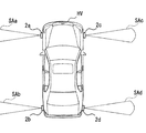
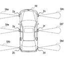
- a driving support system 100 shown in FIG. 1 is mounted on a vehicle, and includes a driving support device 1, a left front side sensor 2a, a left rear side sensor 2b, a right front side sensor 2c, a right rear side sensor 2d, and a wheel speed sensor 3.
- the steering angle sensor 4, the HMI system 5, and the vehicle control ECU 6 are included.
- a vehicle equipped with the driving support system 100 is referred to as a host vehicle.
- the left front side sensor 2a is mounted on the left side surface of the front part of the host vehicle (see HV in FIG. 2), and detects an obstacle present on the left side of the front part of the host vehicle.
- the left rear side sensor 2b is mounted on the left side of the rear part of the host vehicle and detects an obstacle existing on the left side of the rear part of the host vehicle.
- the right front side sensor 2c is mounted on the right side surface of the front portion of the host vehicle and detects an obstacle present on the right side of the front portion of the host vehicle.
- the right rear side sensor 2d is mounted on the right side surface of the rear portion of the host vehicle and detects an obstacle present on the right side of the rear portion of the host vehicle.
- the left front side sensor 2a, left rear side sensor 2b, right front side sensor 2c, and right rear side sensor 2d correspond to obstacle sensors.
- side sensors 2a, the left rear side sensor 2b, the right front side sensor 2c, and the right rear side sensor 2d are described without being distinguished, they are referred to as side sensors 2.
- the side sensor 2 detects the distance to the obstacle by transmitting the exploration wave and receiving the reflected wave of the exploration wave reflected by the obstacle.
- the side sensor 2 may be configured so that the directivity center line is arranged, for example, parallel to the direction of the axle of the host vehicle.
- the side sensor 2 may be configured to start transmission of an exploration wave when the shift position of the host vehicle is a travel position other than the parking position and the neutral position.
- it is good also as a structure which starts transmission of an exploration wave when the ignition power supply of the own vehicle is turned on.
- the detection range of the left front side sensor 2a (see SAa in FIG. 2) and the detection range of the left rear side sensor 2b (see SAb in FIG. 2) Line up in the front-rear direction and on the left side of the vehicle.
- the detection range of the right front side sensor 2c (see SAc in FIG. 2) and the detection range of the right rear side sensor 2d (see SAd in FIG. 2) are on the right side of the vehicle along the front-rear direction of the vehicle. Line up back and forth.
- the wheel speed sensor 3 sequentially outputs a pulse signal corresponding to the rotation speed of each rolling wheel.
- the rudder angle sensor 4 is a sensor that detects the steering angle of the steering of the host vehicle. The steering angle when the host vehicle travels in a straight traveling state is set to the neutral position (0 degree), and the rotation angle from the neutral position is steered. Output sequentially as corners.
- the HMI system 5 includes a combination meter, a display device such as a CID (Center Information Display), a HUD (Head-Up Display), an audio output device such as an audio speaker, an operation device, and a control device such as an HCU (Human Machine Interface Control Unit). I have.
- a display device such as a CID (Center Information Display), a HUD (Head-Up Display), an audio output device such as an audio speaker, an operation device, and a control device such as an HCU (Human Machine Interface Control Unit). I have.
- the combination meter is placed in front of the driver's seat of the vehicle.
- the CID is disposed above the center cluster in the passenger compartment of the host vehicle.
- the combination meter and the CID display various images for information presentation on the display screen based on the image data acquired from the HCU.
- the HUD projects image light based on the image data acquired from the HCU onto a projection area defined in the windshield of the own vehicle. The light of the image reflected on the vehicle interior side by the windshield is perceived by the driver sitting in the driver's seat. The driver can visually recognize the virtual image of the image projected by the HUD by superimposing it on the outside scene in front of the vehicle.
- the audio speaker is placed in the lining of the door of the vehicle.
- the audio speaker presents information to the occupant by the reproduced voice.
- the operation device is a switch group operated by the driver of the own vehicle.
- the operation device is used for performing various settings. For example, as an operation device, there is a steering switch or the like provided in a spoke spoke portion of the own vehicle.
- the HCU includes a memory such as a CPU, a ROM and a RAM, an I / O, and a bus connecting them, and executes various processes by executing a control program stored in the memory. For example, information is presented from a display device and / or an audio output device. Note that some or all of the functions executed by the HCU may be configured in hardware by one or a plurality of ICs.
- the vehicle control ECU 6 is an electronic control device that performs acceleration / deceleration control and / or steering control of the host vehicle.
- the vehicle control ECU 6 includes a steering ECU that performs steering control, a power unit control ECU that performs acceleration / deceleration control, a brake ECU, and the like.
- the vehicle control ECU 6 acquires detection signals output from sensors such as an accelerator position sensor, a brake pedal force sensor, a wheel speed sensor 3, a rudder angle sensor 4, and an acceleration sensor mounted on the host vehicle.
- a control signal is output to each traveling control device such as an actuator and an EPS (Electric Power Steering) motor.
- EPS Electronic Power Steering
- the driving support device 1 includes a CPU, a memory such as a ROM and a RAM, an I / O, and a bus for connecting them, and executes various processes by executing a control program stored in the memory.
- the driving support device 1 executes various processes based on various information input from the side sensor 2, the wheel speed sensor 3, the rudder angle sensor 4, and the like. Note that some or all of the functions executed by the driving support device 1 may be configured in hardware by one or a plurality of ICs.
- This driving support device 1 corresponds to an in-vehicle device.
- the driving support device 1 determines the presence / absence of an obstacle moving body on the side of the vehicle and the moving state of the moving body based on the detection result of the side sensor 2. Further, the driving support device 1 performs driving support such as driving support and / or substitution by the driver based on the detection result of the surrounding monitoring sensor that detects obstacles and / or road markings around the host vehicle. .
- the HMI system 5 is made to present information for notifying the driver of the direction in which the obstacle exists, or the HMI system 5 is warned when moving in the direction in which the obstacle exists. Support.
- the vehicle control ECU 6 executes an automatic driving function that automatically controls acceleration, braking, and / or steering of the host vehicle.
- the vehicle travels so as to maintain the target inter-vehicle distance from the preceding vehicle by adjusting the driving force and braking force based on the detection result of the preceding vehicle acquired from the surrounding monitoring sensor.
- ACC Adaptive Cruise Control
- a steering force is generated in a direction that prevents the approach to the traveling lane line, thereby maintaining the lane while traveling and
- the host vehicle based on the detection result of the traveling lane line in the traveling direction obtained from the surrounding monitoring sensor and the detection result of the moving body on the side, the host vehicle automatically joins to the adjacent lane (in other words, the lane change)
- LCA Lane Change Assist
- the periphery monitoring sensor includes the side sensor 2 as a sensor for monitoring the periphery of the host vehicle.
- a surrounding monitoring sensor a surrounding monitoring camera that captures a predetermined range around the vehicle, a millimeter wave radar that transmits a survey wave to the predetermined range around the vehicle, sonar, LIDAR (LightIDDetection and Ranging / Laser Imaging Detect ion and Ranging ) And other sensors.
- the side sensor 2 may be any one of a peripheral monitoring camera, a millimeter wave radar, a sonar, and a LIDAR, but in the present embodiment, a case where the side sensor 2 is a sonar will be described as an example.
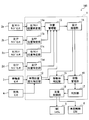
- the driving assistance device 1 includes a left front position specifying unit 11a, a left rear position specifying unit 11b, a right front position specifying unit 11c, a right rear position specifying unit 11d, a vehicle position change specifying unit 12, and position management.
- Unit 13 classification processing unit 14, moving body determination unit 15, state management unit 16, determination unit 17, and support control unit 18.
- the left front position specifying unit 11a detects the position of the obstacle on the left side of the host vehicle from the detection result obtained sequentially from the left front side sensor 2a ( Hereinafter, the first left obstacle position) is identified sequentially. More specifically, among the obstacles, the position of the reflection point that reflects the exploration wave of the left front side sensor 2a is sequentially identified.
- the principle of triangulation is used.
- the position of the reflection point is specified.
- the distance from the left front side sensor 2a to the reflection point may be calculated based on the time from when the exploration wave is transmitted until the reflection wave is received.
- the position of the left front side sensor 2a may be calculated based on the installation position of the left front side sensor 2a relative to the vehicle position and the vehicle position.
- the host vehicle position may be represented by a position in the XY coordinate system with the rear wheel axle center position at a certain time as a reference point and the reference point as the origin.
- the XY coordinate system may be such that the X axis and the Y axis are in the horizontal plane.
- the reference point of the coordinate system is not limited to the center of the rear wheel axle, and may be an arbitrary point.
- the left rear position specifying unit 11b determines the position of the obstacle existing on the left side of the own vehicle with respect to the own vehicle (hereinafter, the second left obstacle position) with respect to the left rear side sensor 2b. Identify sequentially.
- the right front position specifying unit 11c is the same as the left front position specifying unit 11a in that the position of the obstacle present on the right side of the host vehicle relative to the host vehicle with respect to the right front side sensor 2c (hereinafter, the right first obstacle position). Are identified sequentially.
- the right rear position specifying unit 11d determines the position of the obstacle on the right side of the own vehicle with respect to the own vehicle (hereinafter, the right second obstacle position) with respect to the right rear side sensor 2d. Identify sequentially.
- the left front position specifying unit 11a, the left rear position specifying unit 11b, the right front position specifying unit 11c, and the right rear position specifying unit 11d correspond to the position specifying unit.
- the vehicle position change specifying unit 12 determines the change in the vehicle position from the travel distance of the host vehicle obtained from the pulse signal of the wheel speed sensor 3 and the change in the steering angle of the host vehicle sequentially detected by the steering angle sensor 4. Identify.
- the vehicle position change specifying unit 12 is used to specify an obstacle position in the left front position specifying unit 11a, the left rear position specifying unit 11b, the right front position specifying unit 11c, and the right rear position specifying unit 11d.
- the position in the XY coordinate system described above may be sequentially updated in accordance with the change in the specified vehicle position.
- the position management unit 13 stores the obstacle positions specified for each of the plurality of side sensors 2 in, for example, the volatile memory of the driving support device 1, and stores the obstacles according to the displacement of the position of the own vehicle accompanying traveling. Update the object position.
- the obstacle position in the XY coordinate system described above is sequentially updated in accordance with the change in the vehicle position specified by the vehicle position change specifying unit 12.
- the position management unit 13 performs processing using the obstacle positions stored for each of the plurality of side sensors 2.
- the classification processing unit 14 Based on the position difference in the vehicle width direction of the first left obstacle position sequentially specified by the left front position specifying unit 11a, the classification processing unit 14 performs the first left obstacle in units of obstacles having different positions in the vehicle width direction.
- the position is divided sequentially.
- the left first obstacle positions whose position difference in the vehicle width direction is equal to or greater than a predetermined value are separated into different obstacles, while the left first obstacle positions whose position difference in the vehicle width direction is less than a predetermined value Are divided into the same obstacles.
- the fact that the obstacle position is divided into different obstacles indicates that the object detected by the side sensor 2 has been switched to another obstacle.
- the predetermined position here may be a position difference in the vehicle width direction that is difficult to consider as the same obstacle, and is a value that can be arbitrarily set.
- the classification processing unit 14 is also an obstacle unit in which the position in the vehicle width direction is different in the left rear position specifying unit 11b, the right front position specifying unit 11c, and the right rear position specifying unit 11d as in the left front position specifying unit 11a. To divide the left second obstacle position, the right first obstacle position, and the right second obstacle position. Further, the division processing unit 14 also determines that the position difference in the vehicle width direction is less than a predetermined value for the left first obstacle position and the left second obstacle position, and the right first obstacle position and the right second obstacle position. What is necessary is just to set it as the structure which divides things into the same obstacle, respectively.
- the left first obstacle position, the left second obstacle position, the right first obstacle position, and the right second obstacle position classified by the classification processing unit 14 are classified into, for example, the volatile memory of the driving support device 1. What is necessary is just to memorize
- the moving body determination unit 15 moves the obstacle detected by the side sensor 2 based on the difference between the deviation of the obstacle position specified for each of the plurality of side sensors 2 and the deviation of the own vehicle position accompanying traveling. Determine whether the body.
- the case where the host vehicle moves forward and the obstacle on the right side of the host vehicle is detected will be described as an example.
- the moving body determination unit 15 moves the obstacle when both the right first obstacle position and the right second obstacle position have already been identified for the obstacle currently detected detected by the classification processing unit 14. Judge whether the body. As an example, the right first obstacle position specified when the obstacle is first detected by the right front side sensor 2c, and the second right obstacle specified when the obstacle is first detected by the right rear side sensor 2d. It is determined whether the deviation from the object position coincides with the deviation corresponding to the change in the own vehicle position specified by the vehicle position change specifying unit 12.
- the term “match” as used herein is not limited to a configuration in which a match is determined when the match is complete, but may be determined as a match with an allowable range of an error level. When it is determined that they match, the currently detected obstacle is determined as a stationary object. On the other hand, if it is determined that they do not match, the obstacle currently being detected is determined as a moving object.
- the state management unit 16 detects the obstacle detected as the moving object by the moving object determination unit 15, the detection state at the side sensor 2, the specified obstacle position, and the movement state of the obstacle determined by the determination unit 17. Are stored sequentially. About the information of the transition of the detection state in the side sensor 2, what is necessary is just to set it as the structure obtained from the division process part 14. FIG. When only the right first obstacle position is specified for the moving object being detected by the side sensor 2, the detection state is detected only by the right front side sensor 2c. On the other hand, when only the right second obstacle position is specified, the detection state is detected only by the right rear side sensor 2d. When both the right first obstacle position and the right second obstacle position are specified, the detection state is detected by both the right front side sensor 2c and the right rear side sensor 2d.
- the discriminating unit 17 is discriminated by the information stored in the state management unit 16 regarding the transition of the side sensor 2 where the obstacle determined to be a moving object is detected, the identified obstacle position, and the discriminating unit 17.
- the moving state of the moving body relative to the own vehicle is sequentially determined from the history of the moving state of the obstacle. Examples of the moving state include a catch-up state in which the moving body has caught up with the own vehicle, a parallel running state in which the moving body runs parallel to the own vehicle, a passing state in which the moving body overtakes the own vehicle, There are passing states that pass in the opposite direction to the car.
- the support control unit 18 instructs the HMI system 5 and / or the vehicle control ECU 6 based on the detection result of the periphery monitoring sensor that detects obstacles and / or road markings around the host vehicle, for example, as described above. Provide driving assistance like that. Further, the support control unit 18 causes the vehicle to support driving based on the moving state of the moving body that is sequentially determined by the determination unit 17.
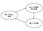
- [Catch-up state] The default is a state where no moving object is detected by any of the right front side sensor 2c and the right rear side sensor 2d.
- the determination unit 17 determines that it is in a catch-up determination waiting state. Then, when the state in which the moving body is detected again by the right rear side sensor 2d continues, the determination unit 17 determines that it is a catch-up state. On the other hand, when a moving body is not detected by the right rear side sensor 2d, it is determined that there is no catch-up state.
- the determination unit 17 may determine that the vehicle is in the catch-up state when the moving object is detected by the right rear side sensor 2d without passing through the catch-up determination waiting state.
- determination part 17 performs the discrimination
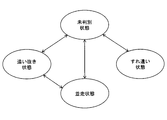
- the parallel running state is a state in which the moving body runs in parallel with the own vehicle
- the overtaking state is a state in which the moving body passes the own vehicle
- the passing state is a state in which the moving body passes in the opposite direction to the own vehicle. It is a state to go.
- the determination of the parallel running state, the overtaking state, and the passing state will be described with reference to FIG.
- the default is unidentified state.
- a moving body hereinafter referred to as a first moving body
- the determining unit 17 determines the moving state of the first moving body as the parallel running state.
- a different moving body (hereinafter referred to as a second moving body) is detected by the right front side sensor 2c at a position farther in the vehicle width direction from the own vehicle than the first moving body detected by the right rear side sensor 2d. ) Is detected, the determination unit 17 determines the moving state of the second moving body as a passing state.
- the individual distinction may be configured according to the obstacle classification in the classification processing unit 14.
- the moving body that is determined to be the catch-up state is used as a comparison target, so that the passing state of the moving body that is likely to be an oncoming vehicle in the oncoming lane can be more easily obtained. It can be determined.
- the right front side sensor 2c detects a moving body (hereinafter referred to as a third moving body) different from the first moving body detected by the right rear side sensor 2d, and the right rear side
- the determination unit 17 determines the moving state of the third moving body as the overtaking state.
- the moving body in the unidentified state, the moving body is detected by the right front side sensor 2c and the moving body is continuously detected, and the moving body is detected by the right rear side sensor 2d.
- the determination unit 17 determines that the moving state of the moving body is the overtaking state.
- the determination unit 17 determines the moving state of the first moving body as the overtaking state. Since it is difficult to accurately determine the moving state of the moving body from the overtaking state simply by the fact that the moving body is no longer detected by the right rear side sensor 2d, the first embodiment is based on the condition that the parallel running state has passed. By identifying the overtaking state, the accuracy of overtaking state determination is improved.
- the determination unit 17 determines the movement state as unidentified state. Return to. Here, the determination unit 17 may determine the movement state of the first moving body as the catch-up fixed state.
- the determination unit 17 In the overtaking state, when the state in which the first moving body is detected by the right front side sensor 2c ends, the determination unit 17 returns the movement state to the undetermined state.
- the state in which the first moving body is detected by the right front side sensor 2c is not limited to a state in which no obstacle is detected by the right front side sensor 2c, but an obstacle other than the first moving body is detected by the right front side sensor 2c. It also includes the state of switching to the state of detecting an object.
- the determination unit 17 performs the parallel movement of the first moving body. Return to the state. This change in the movement state occurs when the first moving body tries to overtake the vehicle and then revisits and returns to parallel running.
- the moving state of the second moving body continues to be determined as the passing state. Then, when neither the right front side sensor 2c nor the right rear side sensor 2d has detected the first moving body and the second moving body, the moving state may be returned to the unidentified state.
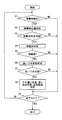
- Movement state determination-related processing an example of processing related to determination of the movement state in the driving support device 1 (hereinafter referred to as movement state determination-related processing) will be described using the flowchart of FIG. 5 may be configured to start when the side sensor 2 is activated, for example.
- step S1 when an obstacle is detected by at least one of the right front side sensor 2c and the right rear side sensor 2d (YES in S1), the process proceeds to step S2. On the other hand, if no obstacle is detected (NO in S1), the process proceeds to step S9.
- step S2 when the right front side sensor 2c detects an obstacle, the right front position specifying unit 11c sequentially specifies the right first obstacle position.
- the right rear position specifying unit 11d sequentially specifies the right second obstacle position.
- the identified obstacle position is classified by the classification processing unit 14 for each obstacle based on the position difference in the vehicle width direction of the obstacle position.
- step S3 both the right first obstacle position and the right second obstacle position have already been identified for the obstacle currently detected that has been classified by the classification processing unit 14, and the obstacle determination unit 15 If it can be determined whether or not the object is a moving object (YES in S3), the process proceeds to step S4. On the other hand, if either the right first obstacle position or the right second obstacle position has not been specified and it cannot be determined whether or not this obstacle is a moving object (NO in S3), the process proceeds to step S9. .
- step S4 the moving body determination unit 15 determines whether or not the currently detected obstacle is a moving body.
- step S5 when it is determined that the object is a moving body in S4 (YES in S5), the process proceeds to step S6.
- step S9 when it is determined that the object is a stationary object in S4 (NO in S5), the process proceeds to step S9.
- step S6 the determination unit 17 determines whether or not the obstacle determined to be a moving body is in a catch-up state.
- step S7 when it is determined in S6 that the moving body is in a catch-up state (YES in S7), the process proceeds to step S8. On the other hand, when it is determined in S6 that the moving body is not in the catch-up state (YES in S7), the process proceeds to step S9.
- step S8 the determination unit 17 determines whether the moving body is in the parallel running state, the overtaking state, or the passing state.
- the moving state of the moving body determined in S8 is used for driving support in the support control unit 18. The use of the moving state of the moving body for driving support will be described in detail later.
- step S9 if it is the end timing of the movement state determination related process (YES in step S9), the movement state determination related process is ended. On the other hand, if it is not the end timing of the movement state determination related process (NO in step S9), the process returns to S1 and the process is repeated.
- An example of the end timing of the movement state determination related process is when the ignition power of the own vehicle is turned off.
- the present invention is not necessarily limited thereto. What is necessary is just to set it as the structure which replaces the side sensor 2 before and behind the own vehicle, and implements the content mentioned above when the own vehicle reverses. Whether the host vehicle moves forward or backward may be determined from the signal of the shift position sensor. When the host vehicle moves backward, in the unidentified state, a different moving body is detected by the right front side sensor 2c at a position closer to the vehicle width direction from the own vehicle than the moving body detected by the right rear side sensor 2d.
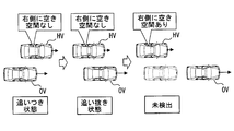
- FIGS. HV in FIGS. 6 to 11 indicates the own vehicle, and OV indicates the other vehicle. 6 to 11 exemplify a case where another vehicle OV travels on the right side of the host vehicle HV.
- the determination result of the empty space is used for route generation at the time of driving support such as generation of a recommended route at the time of manual parking, generation of a parking route at the time of automatic parking, and generation of a travel route at the time of automatic driving.
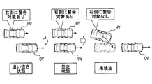
- FIG. 6 shows an example in which the other vehicle OV overtakes the right side of the own vehicle HV.
- the support control unit 18 determines that there is no free space on the right side. Even when the movement state of the other vehicle OV determined by the determination unit 17 changes from the parallel running state to the overtaking state, the support control unit 18 determines that there is no free space on the right side. The support control unit 18 does not generate a route at the time of driving support in the area determined to have no free space.
- the support control unit 18 moves to the right side when the other vehicle OV is not detected. Judge that there is free space.
- the support control unit 18 can generate a route at the time of driving support in an area determined to have free space.
- FIG. 7 shows an example in which another vehicle OV tries to overtake the right side of the own vehicle HV, but stops overtaking and switches to parallel running. Also in the example shown in FIG. 7, as in the example shown in FIG. 6, when the movement state of the other vehicle OV determined by the determination unit 17 is a catch-up state, a parallel running state, or a passing state, the support control unit 18 is on the right side. Judge that there is no free space. Furthermore, also when the movement state of the other vehicle OV determined by the determination unit 17 changes from the overtaking state to the parallel running state, the support control unit 18 determines that there is no free space on the right side. As described above, the support control unit 18 does not generate a route at the time of driving support in the area determined as having no free space.
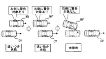
- FIG. 8 and FIG. 9 will be described for use in determining whether a warning is necessary.
- the determination result of the necessity of warning is used for driving support such as avoiding contact with an obstacle.
- FIG. 8 the case where the other vehicle OV overtakes the right side of the own vehicle HV is taken as an example.
- the support control unit 18 determines that there is a warning target on the right side.
- the support control unit 18 determines that there is a warning target on the right side.
- the support control unit 18 instructs the HMI system 5 to give a warning from the display device and / or the audio output device to the driver of the vehicle. Let it be done.
- the support control unit 18 moves to the right side when the other vehicle OV is not detected. Judge that there is no available warning.
- the assistance control unit 18 does not perform the above-described warning when the host vehicle tries to move to an area determined not to be a warning target.
- FIG. 9 shows an example in which another vehicle OV tries to overtake the right side of the own vehicle HV, but stops overtaking and switches to parallel running. Also in the example shown in FIG. 9, as in the example shown in FIG. 8, when the movement state of the other vehicle OV determined by the determination unit 17 is a catch-up state, a parallel running state, or a passing state, the support control unit 18 is on the right side. Judge that there is a warning target. Furthermore, also when the movement state of the other vehicle OV determined by the determination unit 17 changes from the overtaking state to the parallel running state, the support control unit 18 determines that there is a warning target on the right side. As described above, the support control unit 18 causes the above-described warning to be performed when the host vehicle attempts to move to an area where it is determined that there is a warning target.
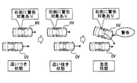
- FIG. 10 shows an example in which the other vehicle OV accelerates and overtakes the own vehicle HV after the own vehicle HV catches up with the other vehicle OV and enters a parallel running state.
- the support control unit 18 determines that there is a warning target on the right side. Even when the movement state of the other vehicle OV determined by the determination unit 17 shifts to the parallel running state, the support control unit 18 determines that there is a warning target on the right side.
- the support control unit 18 instructs the HMI system 5 to give a warning from the display device and / or the audio output device to the driver of the vehicle. Let it be done.
- the support control unit 18 moves to the right side when the other vehicle OV is not detected. Judge that there is no available warning.
- the assistance control unit 18 does not perform the above-described warning when the host vehicle tries to move to an area determined not to be a warning target.
- region judged to have a warning object was shown here, it does not necessarily restrict to this.
- the host vehicle when the host vehicle is about to move to a region that is determined to have a warning target, it automatically controls braking and / or steering to provide driving assistance that restricts movement to the region determined to have a warning target It is good.
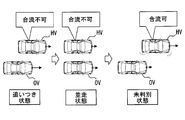
- FIG. 11 shows an example in which the other vehicle OV overtakes the right side of the own vehicle HV.
- the support control unit 18 determines that merging is not possible. If the support control unit 18 determines that the merging is not possible, the support control unit 18 does not notify the merging timing to the adjacent lane and does not start the automatic merging. In other words, merging is not allowed.
- the support control unit 18 determines that the merging is possible. When it is determined that the merge is possible, the support control unit 18 notifies the merge timing to the adjacent lane, or turns on the blinker lamp of the own vehicle to start the automatic merge. That is, merging is permitted.
- FIG. 12 shows an example in which the other vehicle OV tries to overtake the right side of the own vehicle HV but stops overtaking and descends to the rear of the own vehicle. Also in the example shown in FIG. 12, as in the example shown in FIG. 11, when the movement state of the other vehicle OV determined by the determination unit 17 is a catch-up state or a parallel running state, the support control unit 18 determines that merging is not possible. . On the other hand, when the movement state of the other vehicle OV determined by the determination unit 17 changes from the overtaking state to the parallel running state and the unidentified state, the support control unit 18 determines that the merging is possible. As described above, when it is determined that merging is possible, the support control unit 18 notifies the merging timing to the adjacent lane, or turns on the blinker lamp of the own vehicle to start automatic merging. .
- the right front side sensor 2c no longer detects a moving object after determining the overtaking state, it notifies the merging timing to the adjacent lane, or turns on the turn signal lamp of its own vehicle to automatically merge. It may be configured to start.
- notification of the merging timing to the adjacent lane is performed or the turn signal lamp of the own vehicle is turned on to automatically It is good also as a structure which starts the merge in.
- the transition mode of the side sensor 2 in which an obstacle is detected is It depends on the movement state of obstacles against. For example, from which side sensor 2 the obstacle is detected in order depends on which direction the obstacle is approaching from the front or back of the vehicle. Also, the side sensor 2 from which the obstacle is not detected in order differs depending on the direction in which the obstacle moves in front of or behind the host vehicle. In addition, whether or not an obstacle is continuously detected by the obstacle sensor differs depending on whether the obstacle runs parallel to or away from the vehicle.
- the determination unit 17 based on the transition of the side sensor 2 in which an obstacle is detected from among the plurality of side sensors 2, the determination unit 17 has the obstacle's own vehicle on the side of the vehicle. Since the movement state with respect to the vehicle is sequentially determined, it is possible to determine the change in the traveling state of the moving body on the side of the vehicle. Further, as described above, driving assistance can be performed in accordance with a change in the traveling state of the moving body on the side of the host vehicle.
- the moving state is determined when the obstacle detected by the side sensor 2 is determined to be a moving body, it is possible to save the trouble of determining the moving state of the stationary object. Can do.
- the side sensor 2 In the first embodiment, as the side sensor 2, the configuration using the two side sensors 2 arranged in the front-rear direction of the own vehicle is shown as the side sensor 2, but the detection range is widened in at least one side of the own vehicle.
- the side sensor 2 may be configured to use three or more side sensors 2 each having a detection range that extends in at least one side of the host vehicle in the front-rear direction of the host vehicle (hereinafter referred to as a second embodiment).
- the left front side sensor 2a, the left center side sensor 2e, the left rear side sensor 2b, the right front side sensor 2c, the right center side sensor 2f, and the right rear side sensor 2d are taken as an example. To explain.
- the left center side sensor 2e is mounted on the left side of the central part of the own vehicle (see HV in FIG. 12) and detects an obstacle present on the left side of the central part of the own vehicle.
- the right center side sensor 2f is mounted on the right side surface of the center portion of the host vehicle and detects an obstacle present on the right side of the center portion of the host vehicle.
- the left center side sensor 2e and the right center side sensor 2f also correspond to obstacle sensors.
- the detection range of the left front side sensor 2a (see SAa in FIG. 13), the detection range of the left center side sensor 2e (see SAe in FIG. 13), and the detection range of the left rear side sensor 2b (See SAb in FIG. 13) is lined up and down on the left side of the vehicle along the longitudinal direction of the vehicle.
- the driving support device 1 sets the position of the obstacle detected by the left center side sensor 2e and the position of the obstacle detected by the right center side sensor 2f as in the case of the other side sensors 2. Identify. Then, in the same manner as in the first embodiment, the mobile body determination unit 15 determines the side based on the difference between the obstacle position deviation specified for each of the plurality of side sensors 2 and the own vehicle position deviation accompanying traveling. It is determined whether or not the obstacle detected by the sensor 2 is a moving object. For example, in the second embodiment, in order to be able to quickly start moving body determination, the position and / or detection range in the front-rear direction of the vehicle is shifted and traveled between obstacle positions for the side sensors 2 that are close to each other. It is good also as a structure which performs a mobile body determination based on the difference with the deviation
- the discriminating unit 17 uses the information about the transition of the side sensor 2 in which the obstacle determined to be a moving object, which is subdivided compared to the first embodiment, is used.
- the moving state is determined in more detail than in the first embodiment.
- the overtaking state is determined in two stages according to the number of side sensors 2 that are in a state where no moving body is detected.
Landscapes
- Engineering & Computer Science (AREA)
- Physics & Mathematics (AREA)
- Remote Sensing (AREA)
- Radar, Positioning & Navigation (AREA)
- General Physics & Mathematics (AREA)
- Mechanical Engineering (AREA)
- Transportation (AREA)
- Automation & Control Theory (AREA)
- Computer Networks & Wireless Communication (AREA)
- Electromagnetism (AREA)
- Mathematical Physics (AREA)
- Acoustics & Sound (AREA)
- Traffic Control Systems (AREA)
- Measurement Of Velocity Or Position Using Acoustic Or Ultrasonic Waves (AREA)
- Control Of Driving Devices And Active Controlling Of Vehicle (AREA)
Priority Applications (3)
| Application Number | Priority Date | Filing Date | Title |
|---|---|---|---|
| US16/083,705 US10857999B2 (en) | 2016-03-18 | 2017-02-01 | Vehicle device |
| DE112017001417.4T DE112017001417B4 (de) | 2016-03-18 | 2017-02-01 | Fahrzeugvorrichtung |
| CN201780008231.9A CN108604422A (zh) | 2016-03-18 | 2017-02-01 | 车载装置 |
Applications Claiming Priority (2)
| Application Number | Priority Date | Filing Date | Title |
|---|---|---|---|
| JP2016-055970 | 2016-03-18 | ||
| JP2016055970A JP6500820B2 (ja) | 2016-03-18 | 2016-03-18 | 車載装置 |
Publications (1)
| Publication Number | Publication Date |
|---|---|
| WO2017159092A1 true WO2017159092A1 (ja) | 2017-09-21 |
Family
ID=59850817
Family Applications (1)
| Application Number | Title | Priority Date | Filing Date |
|---|---|---|---|
| PCT/JP2017/003503 Ceased WO2017159092A1 (ja) | 2016-03-18 | 2017-02-01 | 車載装置 |
Country Status (5)
| Country | Link |
|---|---|
| US (1) | US10857999B2 (enExample) |
| JP (1) | JP6500820B2 (enExample) |
| CN (1) | CN108604422A (enExample) |
| DE (1) | DE112017001417B4 (enExample) |
| WO (1) | WO2017159092A1 (enExample) |
Cited By (1)
| Publication number | Priority date | Publication date | Assignee | Title |
|---|---|---|---|---|
| CN108189754A (zh) * | 2017-12-23 | 2018-06-22 | 西安科技大学 | 一种多点式主动探测的汽车防撞方法 |
Families Citing this family (11)
| Publication number | Priority date | Publication date | Assignee | Title |
|---|---|---|---|---|
| RU2676359C1 (ru) * | 2015-09-18 | 2018-12-28 | Ниссан Мотор Ко., Лтд. | Устройство отображения транспортного средства и способ отображения транспортного средства |
| EP3842310B1 (en) * | 2016-09-09 | 2023-05-03 | Nissan Motor Co., Ltd. | Vehicle travel control method and travel control device |
| JP6971187B2 (ja) * | 2018-03-28 | 2021-11-24 | 京セラ株式会社 | 画像処理装置、撮像装置、および移動体 |
| US11113971B2 (en) * | 2018-06-12 | 2021-09-07 | Baidu Usa Llc | V2X communication-based vehicle lane system for autonomous vehicles |
| DE102020204078A1 (de) * | 2019-11-27 | 2021-05-27 | Robert Bosch Gesellschaft mit beschränkter Haftung | Fahrerassistenzsystem für Kraftfahrzeuge |
| US11718296B2 (en) * | 2019-12-09 | 2023-08-08 | Bendix Commercial Vehicle Systems Llc | Using shared traffic information to support adaptive cruise control (ACC) between platooning vehicles |
| JP7481070B2 (ja) * | 2020-03-31 | 2024-05-10 | パナソニックオートモーティブシステムズ株式会社 | 車両制御装置、車両用合流支援装置及び車両 |
| BE1028777B1 (nl) * | 2021-03-25 | 2022-06-01 | Ivex | Systeem en methode voor het detecteren van inconsistenties in de outputs van perceptiesystemen van autonome voertuigen |
| JP7631073B2 (ja) | 2021-03-31 | 2025-02-18 | 本田技研工業株式会社 | 車両制御装置及び車両、並びに、車両制御装置の制御方法及びプログラム |
| JP7705265B2 (ja) * | 2021-03-31 | 2025-07-09 | 本田技研工業株式会社 | 車両制御装置及び車両、並びに、車両制御装置の制御方法及びプログラム |
| JP7700771B2 (ja) * | 2022-10-26 | 2025-07-01 | トヨタ自動車株式会社 | 運転支援装置、運転支援方法、及びプログラム |
Citations (6)
| Publication number | Priority date | Publication date | Assignee | Title |
|---|---|---|---|---|
| JP2004331023A (ja) * | 2003-05-12 | 2004-11-25 | Nissan Motor Co Ltd | 車両用運転操作補助装置およびその装置を備えた車両 |
| WO2011128940A1 (ja) * | 2010-04-15 | 2011-10-20 | 三菱電機株式会社 | 走行支援装置 |
| JP2011221673A (ja) * | 2010-04-06 | 2011-11-04 | Seiko Precision Inc | 警報制御装置、警報制御プログラム、及び警報システム |
| JP2013020458A (ja) * | 2011-07-12 | 2013-01-31 | Daihatsu Motor Co Ltd | 車載用物体判別装置 |
| JP2014048205A (ja) * | 2012-08-31 | 2014-03-17 | Toyota Motor Corp | 運転支援システムおよび運転支援方法 |
| JP2014076689A (ja) * | 2012-10-09 | 2014-05-01 | Toyota Motor Corp | 車両制御装置 |
Family Cites Families (25)
| Publication number | Priority date | Publication date | Assignee | Title |
|---|---|---|---|---|
| US5339075A (en) * | 1992-11-24 | 1994-08-16 | Terrill Abst | Vehicular collision avoidance apparatus |
| US5670935A (en) * | 1993-02-26 | 1997-09-23 | Donnelly Corporation | Rearview vision system for vehicle including panoramic view |
| JPH08185599A (ja) * | 1994-12-28 | 1996-07-16 | Nissan Motor Co Ltd | 車両用後側方監視装置 |
| US6891563B2 (en) * | 1996-05-22 | 2005-05-10 | Donnelly Corporation | Vehicular vision system |
| US6618672B2 (en) * | 1998-10-21 | 2003-09-09 | Yazaki Corporation | Vehicle-applied rear-and-side monitoring system |
| JP2003501635A (ja) * | 1999-05-26 | 2003-01-14 | ローベルト ボッシュ ゲゼルシャフト ミット ベシュレンクテル ハフツング | 対象検出システム |
| US7366595B1 (en) * | 1999-06-25 | 2008-04-29 | Seiko Epson Corporation | Vehicle drive assist system |
| JP4615139B2 (ja) * | 2001-03-30 | 2011-01-19 | 本田技研工業株式会社 | 車両の周辺監視装置 |
| US6914521B2 (en) * | 2002-04-12 | 2005-07-05 | Lear Corporation | Visual display for vehicle |
| US6680689B1 (en) * | 2003-03-28 | 2004-01-20 | Visteon Global Technologies, Inc. | Method for determining object classification from side-looking sensor data |
| JP3985748B2 (ja) * | 2003-07-08 | 2007-10-03 | 日産自動車株式会社 | 車載用障害物検出装置 |
| WO2005073754A1 (en) * | 2004-02-02 | 2005-08-11 | Sjoenell Goeran | Vehicle collision detector |
| US7289019B1 (en) * | 2004-05-13 | 2007-10-30 | Jon Kertes | Vehicle avoidance collision system |
| DE102006043149B4 (de) | 2006-09-14 | 2024-08-01 | Bayerische Motoren Werke Aktiengesellschaft | Integrierter Quer- und Längsführungsassistent zur Unterstützung des Fahrers beim Fahrspurwechsel |
| DE102006047634A1 (de) * | 2006-10-09 | 2008-04-10 | Robert Bosch Gmbh | Verfahren zum Erfassen eines Umfelds eines Fahrzeugs |
| JP2009262898A (ja) * | 2008-04-30 | 2009-11-12 | Toyota Central R&D Labs Inc | 移動体の障害物検出装置、及びプログラム |
| DE102010001258A1 (de) | 2010-01-27 | 2011-07-28 | Robert Bosch GmbH, 70469 | Fahrerassistenzverfahren |
| DE102011102557A1 (de) * | 2011-05-26 | 2012-11-29 | Valeo Schalter Und Sensoren Gmbh | Fahrerassistenzeinrichtung mit einer Mehrzahl von Ultraschallsensoren sowie Fahrzeug mit einer derartigen Fahrerassistenzeinrichtung und Verfahren zum Betreiben einer Fahrerassistenzeinrichtung |
| DE102012206790A1 (de) * | 2012-04-25 | 2013-10-31 | Robert Bosch Gmbh | Verfahren für ein Assistenzsystem eines Fahrzeugs |
| JP5965276B2 (ja) * | 2012-10-09 | 2016-08-03 | 株式会社日本自動車部品総合研究所 | 物体検知装置 |
| US9863928B1 (en) * | 2013-03-20 | 2018-01-09 | United Parcel Service Of America, Inc. | Road condition detection system |
| JP6065106B2 (ja) * | 2013-04-10 | 2017-01-25 | トヨタ自動車株式会社 | 車両運転支援装置 |
| JP2014241115A (ja) * | 2013-06-12 | 2014-12-25 | トヨタ自動車株式会社 | 周辺物体検知装置 |
| JP6379384B2 (ja) | 2014-09-09 | 2018-08-29 | コニカミノルタ株式会社 | 後処理装置及び画像形成システム |
| JP6462328B2 (ja) * | 2014-11-18 | 2019-01-30 | 日立オートモティブシステムズ株式会社 | 走行制御システム |
-
2016
- 2016-03-18 JP JP2016055970A patent/JP6500820B2/ja active Active
-
2017
- 2017-02-01 DE DE112017001417.4T patent/DE112017001417B4/de active Active
- 2017-02-01 US US16/083,705 patent/US10857999B2/en active Active
- 2017-02-01 CN CN201780008231.9A patent/CN108604422A/zh active Pending
- 2017-02-01 WO PCT/JP2017/003503 patent/WO2017159092A1/ja not_active Ceased
Patent Citations (6)
| Publication number | Priority date | Publication date | Assignee | Title |
|---|---|---|---|---|
| JP2004331023A (ja) * | 2003-05-12 | 2004-11-25 | Nissan Motor Co Ltd | 車両用運転操作補助装置およびその装置を備えた車両 |
| JP2011221673A (ja) * | 2010-04-06 | 2011-11-04 | Seiko Precision Inc | 警報制御装置、警報制御プログラム、及び警報システム |
| WO2011128940A1 (ja) * | 2010-04-15 | 2011-10-20 | 三菱電機株式会社 | 走行支援装置 |
| JP2013020458A (ja) * | 2011-07-12 | 2013-01-31 | Daihatsu Motor Co Ltd | 車載用物体判別装置 |
| JP2014048205A (ja) * | 2012-08-31 | 2014-03-17 | Toyota Motor Corp | 運転支援システムおよび運転支援方法 |
| JP2014076689A (ja) * | 2012-10-09 | 2014-05-01 | Toyota Motor Corp | 車両制御装置 |
Cited By (1)
| Publication number | Priority date | Publication date | Assignee | Title |
|---|---|---|---|---|
| CN108189754A (zh) * | 2017-12-23 | 2018-06-22 | 西安科技大学 | 一种多点式主动探测的汽车防撞方法 |
Also Published As
| Publication number | Publication date |
|---|---|
| CN108604422A (zh) | 2018-09-28 |
| JP2017173903A (ja) | 2017-09-28 |
| DE112017001417B4 (de) | 2023-03-02 |
| US10857999B2 (en) | 2020-12-08 |
| JP6500820B2 (ja) | 2019-04-17 |
| DE112017001417T5 (de) | 2018-12-06 |
| US20190071077A1 (en) | 2019-03-07 |
Similar Documents
| Publication | Publication Date | Title |
|---|---|---|
| JP6500820B2 (ja) | 車載装置 | |
| US11458957B2 (en) | Vehicle surrounding display apparatus | |
| US9751562B2 (en) | Park exit assist system | |
| US10843706B2 (en) | Vehicle control apparatus | |
| JP6294905B2 (ja) | 表示装置 | |
| JP6520177B2 (ja) | 運転制御装置、運転制御方法 | |
| JP6447468B2 (ja) | 運転支援装置 | |
| US10377416B2 (en) | Driving assistance device | |
| JP6304272B2 (ja) | 車両用注意喚起装置 | |
| US20190084572A1 (en) | Driving support apparatus | |
| TWI755869B (zh) | 具備fcw控制裝置之傾斜車輛 | |
| US10055994B2 (en) | Parking assistance device | |
| JP2016084094A (ja) | 駐車支援装置 | |
| JP2017100681A (ja) | 走行制御装置 | |
| US11299163B2 (en) | Control system of vehicle, control method of the same, and non-transitory computer-readable storage medium | |
| WO2018173582A1 (ja) | 運転支援装置 | |
| JP7141470B2 (ja) | 駐車支援装置及び駐車支援方法 | |
| CN116605136B (zh) | 车辆用警报装置 | |
| JP2017114195A (ja) | 車両制御装置 | |
| JPWO2019038918A1 (ja) | 走行制御装置、および車両 | |
| WO2022249837A1 (ja) | 機能制御装置、機能制御プログラム、自動運転制御装置、及び自動運転制御プログラム | |
| US12583454B2 (en) | Reverse support apparatus | |
| JP2019011055A (ja) | 運転支援装置 | |
| JP2025067926A (ja) | 車両用制御装置及び車両用制御方法 | |
| JP6227514B2 (ja) | 駐車支援装置 |
Legal Events
| Date | Code | Title | Description |
|---|---|---|---|
| 121 | Ep: the epo has been informed by wipo that ep was designated in this application |
Ref document number: 17766100 Country of ref document: EP Kind code of ref document: A1 |
|
| 122 | Ep: pct application non-entry in european phase |
Ref document number: 17766100 Country of ref document: EP Kind code of ref document: A1 |