WO2017154776A1 - リチウムイオン電池用増粘剤粉末、水系電極スラリー、リチウムイオン電池用電極、リチウムイオン電池、リチウムイオン電池用水系電極スラリーの製造方法およびリチウムイオン電池用電極の製造方法 - Google Patents
リチウムイオン電池用増粘剤粉末、水系電極スラリー、リチウムイオン電池用電極、リチウムイオン電池、リチウムイオン電池用水系電極スラリーの製造方法およびリチウムイオン電池用電極の製造方法 Download PDFInfo
- Publication number
- WO2017154776A1 WO2017154776A1 PCT/JP2017/008513 JP2017008513W WO2017154776A1 WO 2017154776 A1 WO2017154776 A1 WO 2017154776A1 JP 2017008513 W JP2017008513 W JP 2017008513W WO 2017154776 A1 WO2017154776 A1 WO 2017154776A1
- Authority
- WO
- WIPO (PCT)
- Prior art keywords
- aqueous
- lithium ion
- thickener
- electrode
- water
- Prior art date
- Legal status (The legal status is an assumption and is not a legal conclusion. Google has not performed a legal analysis and makes no representation as to the accuracy of the status listed.)
- Ceased
Links
Images
Classifications
-
- H—ELECTRICITY
- H01—ELECTRIC ELEMENTS
- H01M—PROCESSES OR MEANS, e.g. BATTERIES, FOR THE DIRECT CONVERSION OF CHEMICAL ENERGY INTO ELECTRICAL ENERGY
- H01M4/00—Electrodes
- H01M4/02—Electrodes composed of, or comprising, active material
- H01M4/62—Selection of inactive substances as ingredients for active masses, e.g. binders, fillers
- H01M4/621—Binders
- H01M4/622—Binders being polymers
-
- C—CHEMISTRY; METALLURGY
- C09—DYES; PAINTS; POLISHES; NATURAL RESINS; ADHESIVES; COMPOSITIONS NOT OTHERWISE PROVIDED FOR; APPLICATIONS OF MATERIALS NOT OTHERWISE PROVIDED FOR
- C09K—MATERIALS FOR MISCELLANEOUS APPLICATIONS, NOT PROVIDED FOR ELSEWHERE
- C09K3/00—Materials not provided for elsewhere
-
- H—ELECTRICITY
- H01—ELECTRIC ELEMENTS
- H01M—PROCESSES OR MEANS, e.g. BATTERIES, FOR THE DIRECT CONVERSION OF CHEMICAL ENERGY INTO ELECTRICAL ENERGY
- H01M10/00—Secondary cells; Manufacture thereof
- H01M10/05—Accumulators with non-aqueous electrolyte
- H01M10/052—Li-accumulators
- H01M10/0525—Rocking-chair batteries, i.e. batteries with lithium insertion or intercalation in both electrodes; Lithium-ion batteries
-
- H—ELECTRICITY
- H01—ELECTRIC ELEMENTS
- H01M—PROCESSES OR MEANS, e.g. BATTERIES, FOR THE DIRECT CONVERSION OF CHEMICAL ENERGY INTO ELECTRICAL ENERGY
- H01M4/00—Electrodes
- H01M4/02—Electrodes composed of, or comprising, active material
- H01M4/62—Selection of inactive substances as ingredients for active masses, e.g. binders, fillers
-
- H—ELECTRICITY
- H01—ELECTRIC ELEMENTS
- H01M—PROCESSES OR MEANS, e.g. BATTERIES, FOR THE DIRECT CONVERSION OF CHEMICAL ENERGY INTO ELECTRICAL ENERGY
- H01M4/00—Electrodes
- H01M4/02—Electrodes composed of, or comprising, active material
- H01M4/64—Carriers or collectors
- H01M4/66—Selection of materials
- H01M4/663—Selection of materials containing carbon or carbonaceous materials as conductive part, e.g. graphite, carbon fibres
-
- H—ELECTRICITY
- H01—ELECTRIC ELEMENTS
- H01M—PROCESSES OR MEANS, e.g. BATTERIES, FOR THE DIRECT CONVERSION OF CHEMICAL ENERGY INTO ELECTRICAL ENERGY
- H01M4/00—Electrodes
- H01M4/02—Electrodes composed of, or comprising, active material
- H01M4/13—Electrodes for accumulators with non-aqueous electrolyte, e.g. for lithium-accumulators; Processes of manufacture thereof
- H01M4/133—Electrodes based on carbonaceous material, e.g. graphite-intercalation compounds or CFx
-
- H—ELECTRICITY
- H01—ELECTRIC ELEMENTS
- H01M—PROCESSES OR MEANS, e.g. BATTERIES, FOR THE DIRECT CONVERSION OF CHEMICAL ENERGY INTO ELECTRICAL ENERGY
- H01M4/00—Electrodes
- H01M4/02—Electrodes composed of, or comprising, active material
- H01M4/13—Electrodes for accumulators with non-aqueous electrolyte, e.g. for lithium-accumulators; Processes of manufacture thereof
- H01M4/139—Processes of manufacture
- H01M4/1393—Processes of manufacture of electrodes based on carbonaceous material, e.g. graphite-intercalation compounds or CFx
-
- H—ELECTRICITY
- H01—ELECTRIC ELEMENTS
- H01M—PROCESSES OR MEANS, e.g. BATTERIES, FOR THE DIRECT CONVERSION OF CHEMICAL ENERGY INTO ELECTRICAL ENERGY
- H01M4/00—Electrodes
- H01M4/02—Electrodes composed of, or comprising, active material
- H01M4/62—Selection of inactive substances as ingredients for active masses, e.g. binders, fillers
- H01M4/621—Binders
-
- Y—GENERAL TAGGING OF NEW TECHNOLOGICAL DEVELOPMENTS; GENERAL TAGGING OF CROSS-SECTIONAL TECHNOLOGIES SPANNING OVER SEVERAL SECTIONS OF THE IPC; TECHNICAL SUBJECTS COVERED BY FORMER USPC CROSS-REFERENCE ART COLLECTIONS [XRACs] AND DIGESTS
- Y02—TECHNOLOGIES OR APPLICATIONS FOR MITIGATION OR ADAPTATION AGAINST CLIMATE CHANGE
- Y02E—REDUCTION OF GREENHOUSE GAS [GHG] EMISSIONS, RELATED TO ENERGY GENERATION, TRANSMISSION OR DISTRIBUTION
- Y02E60/00—Enabling technologies; Technologies with a potential or indirect contribution to GHG emissions mitigation
- Y02E60/10—Energy storage using batteries
Definitions
- the present invention relates to a thickener powder for a lithium ion battery, an aqueous electrode slurry, an electrode for a lithium ion battery, a lithium ion battery, a method for producing an aqueous electrode slurry for a lithium ion battery, and a method for producing an electrode for a lithium ion battery.
- An electrode used in a lithium ion battery is generally mainly composed of an electrode active material layer and a current collector.
- the electrode active material layer is obtained, for example, by applying an aqueous electrode slurry containing an electrode active material, a thickener, an aqueous binder, etc. to the surface of a current collector such as a metal foil and drying.
- Examples of the method for producing an electrode for a lithium ion battery include the methods described in Patent Document 1 and Patent Document 2.
- Patent Document 1 Japanese Patent Laid-Open No. 2006-24550 includes a mixture containing an active material A, a conductive material B, a binder C and a thickener D, and a liquid component E that dissolves the thickener D.
- a step of preparing a mixture paint comprising a conductive material B comprising at least a carbon material, a thickener D comprising at least a water-soluble polymer, and a liquid component E comprising at least water;
- the step a for preparing the mixture paint is kneaded with the liquid component E with the compound containing the active material A, the conductive material B and the powder thickener D.
- a positive electrode of a non-aqueous secondary battery having a primary kneading step for obtaining a primary kneaded product, and a secondary kneading step for kneading the primary kneaded product together with the binder C and an additional liquid component to obtain a secondary kneaded product
- An electrode plate manufacturing method is described.
- Patent Document 2 Japanese Patent Application Laid-Open No. 2006-107896 discloses a negative electrode for a non-aqueous secondary battery using a paste formed by kneading and dispersing a carbon material mainly composed of graphite, a thickener, and a binder.
- graphite has an iron content of 500 ppm or less
- the thickener is a water-soluble polymer containing a carboxyl group
- the binder is a water-dispersible polymer having a polar group.
- the kneading step of the paste for forming the negative electrode coating film is carried out by adding a thickener in powder form at least to graphite, and kneading and kneading the kneaded product of the initial kneading step with the dispersion medium. It includes three steps: a dilution kneading step, and a final kneading step in which a binder is added to the kneaded product of the dilution kneading step to create a paste by kneading. And work It describes a method of preparing the negative electrode of the electrode plates of nonaqueous secondary batteries, characterized by at least 2.5 times the shear force of the kneading under kneading step.
- the aqueous electrode slurry obtained by the production method as described in Patent Documents 1 and 2 may vary in viscosity from lot to lot, or the viscosity may change during storage. It has become clear that the quality may not be stable. Moreover, it became clear that the aggregate produced easily in the electrode produced using the water-system electrode slurry whose quality is not stabilized. Furthermore, according to the study by the present inventors, when preparing the aqueous electrode slurry, the aqueous electrode slurry obtained by the method of adding the thickener aqueous solution in a divided manner also varies in viscosity from lot to lot, It became clear that the quality may not be stable due to changes in viscosity during storage. That is, according to the study by the present inventors, it has been clarified that the conventional aqueous electrode slurry is inferior in quality stability.
- the present invention has been made in view of the above circumstances, a thickener powder for a lithium ion battery capable of stably obtaining an aqueous electrode slurry excellent in quality stability, and an aqueous electrode slurry excellent in quality stability.
- An electrode for a lithium ion battery excellent in appearance and a lithium ion battery using the electrode are provided.
- the present inventors have intensively studied to achieve the above problems.
- the measure of the content of water-insoluble components in the thickener powder calculated under specific conditions is effective as a design guideline for stably obtaining an aqueous electrode slurry with excellent quality stability.
- the present invention has been completed.
- a thickener powder used for thickening an aqueous electrode slurry for a lithium ion battery, Including cellulosic water-soluble polymers, A thickener powder for a lithium ion battery in which the content of a water-insoluble component in the thickener powder calculated according to the following condition 1 is 1.0% by mass or less is provided.
- the thickener powder is dissolved in water to obtain a thickener aqueous solution having a concentration of 1.3% by mass.
- the thickener aqueous solution is filtered with a filter having an average pore diameter of 1 ⁇ m.
- the water-insoluble component left above is dried and the mass of the water-insoluble component is measured, and then the content of the water-insoluble component in the thickener powder is calculated.
- An electrode active material selected from a positive electrode active material and a negative electrode active material; An aqueous binder, The thickener powder for lithium ion battery, An aqueous medium; Including An aqueous electrode slurry in which the thickener powder for a lithium ion battery is dissolved in the aqueous medium is provided.
- An electrode active material selected from a positive electrode active material and a negative electrode active material; An aqueous binder, The thickener powder for lithium ion battery, An electrode for a lithium ion battery is provided.
- a lithium ion battery comprising at least a positive electrode, an electrolyte, and a negative electrode
- a lithium ion battery in which at least one of the positive electrode and the negative electrode includes the electrode for a lithium ion battery.
- An electrode active material selected from a positive electrode active material and a negative electrode active material, an aqueous binder, a thickener, and an aqueous medium a method for producing an aqueous electrode slurry for a lithium ion battery, Filtering the thickener aqueous solution with a filter; A step of obtaining a thickener powder by drying the thickener aqueous solution after filtration; A step of preparing an aqueous electrode slurry by mixing an electrode active material, an aqueous binder, the obtained thickener powder and an aqueous medium; A method for producing an aqueous electrode slurry for lithium ion batteries is provided.
- the thickener powder for lithium ion batteries which can obtain stably the aqueous electrode slurry excellent in quality stability, the aqueous electrode slurry excellent in quality stability, and the lithium ion battery excellent in the external appearance Electrode and a lithium ion battery using the electrode can be provided.
- the thickener powder (p) for a lithium ion battery is a thickener powder used for thickening an aqueous electrode slurry for a lithium ion battery, and includes a cellulose-based water-soluble polymer, and the following conditions:
- the content of the water-insoluble component in the thickener powder (p) calculated by 1 is 1.0% by mass or less, preferably 0.8% by mass or less, more preferably 0.5% by mass or less, and still more preferably Is 0.3% by mass or less, more preferably 0.1% by mass or less, and particularly preferably 0.08% by mass or less.
- the content of the water-insoluble component in the thickener powder (p) is preferably 0.01% by mass or more, more preferably 0.02% by mass or more, further preferably 0.04% by mass or more, and even more. Preferably it is 0.06 mass% or more.
- Condition 1 The thickener powder is dissolved in water to obtain a thickener aqueous solution having a concentration of 1.3% by mass. Subsequently, the thickener aqueous solution is filtered with a filter having an average pore diameter of 1 ⁇ m. Next, the water-insoluble component remaining on the filter is dried, and the mass of the water-insoluble component is measured. Next, the content of the water-insoluble component in the thickener powder (p) is calculated.
- the aqueous electrode slurry obtained by the production method as described in Patent Documents 1 and 2 may vary in viscosity from lot to lot, or the viscosity may change during storage. It has become clear that the quality may not be stable. Moreover, it became clear that the aggregate produced easily in the electrode produced using the water-system electrode slurry whose quality is not stabilized. Furthermore, according to the study by the present inventors, when preparing the aqueous electrode slurry, the aqueous electrode slurry obtained by the method of adding the thickener aqueous solution in a divided manner also varies in viscosity from lot to lot, It became clear that the quality may not be stable due to changes in viscosity during storage. That is, according to the study by the present inventors, it has been clarified that the conventional aqueous electrode slurry is inferior in quality stability.
- the present inventors have intensively studied to achieve the above-mentioned problems. As a result, it has been clarified that conventionally used thickener powder contains a water-insoluble component, and that the quality stability of the resulting aqueous electrode slurry decreases when a specific amount of this water-insoluble component is contained. It was. In addition, in the method of adding the thickener aqueous solution in a divided manner, it became clear that the quality stability of the aqueous electrode slurry is lowered because the thickener aqueous solution is added even after the kneading step. Therefore, the present inventor has further studied diligently.
- the thickener powder (p) according to this embodiment in which the content of the water-insoluble component calculated by the above condition 1 is not more than the above upper limit value, an aqueous electrode slurry having excellent quality stability is obtained. It can be obtained stably. And the electrode for lithium ion batteries excellent in the external appearance can be stably obtained by using such an aqueous electrode slurry.
- the thickener powder (p) contains a cellulose-based water-soluble polymer as a main component.
- containing a cellulose-based water-soluble polymer as a main component means that the thickener powder (p) contains 50% by mass or more of the cellulose-based water-soluble polymer.
- the thickener powder (p) preferably contains a cellulose-based water-soluble polymer in an amount of 70% by mass or more, more preferably 90% by mass or more, and particularly preferably 99% by mass or more.
- the cellulose-based water-soluble polymer is not particularly limited as long as it improves the coatability of the aqueous electrode slurry.
- cellulose-based water-soluble polymer examples include cellulose polymers such as carboxymethylcellulose, hydroxymethylcellulose, hydroxyethylcellulose, methylethylhydroxycellulose, methylcellulose, hydroxypropylcellulose, and ammonium salts and alkali metal salts of these cellulose polymers. 1 type, or 2 or more types selected from the cellulose-type polymer salt of this can be used. Among these, it is preferable to include at least one selected from carboxymethyl cellulose and carboxymethyl cellulose salt, one or more selected from carboxymethyl cellulose, ammonium salt of carboxymethyl cellulose, sodium salt of carboxymethyl cellulose and potassium salt of carboxymethyl cellulose It is more preferable to contain.
- cellulose polymers such as carboxymethylcellulose, hydroxymethylcellulose, hydroxyethylcellulose, methylethylhydroxycellulose, methylcellulose, hydroxypropylcellulose, and ammonium salts and alkali metal salts of these cellulose polymers. 1 type, or 2 or more types selected from the cellulose-
- the water-insoluble component is not particularly limited, but includes, for example, a fiber component derived from the cellulose-based water-soluble polymer.
- the viscosity calculated according to the following condition 2 is preferably 10 mPa ⁇ s or more and 20000 mPa ⁇ s or less, and is 100 mPa ⁇ s or more and 10000 mPa ⁇ s or less. More preferably, it is 1000 mPa ⁇ s or more and 8000 mPa ⁇ s or less, and particularly preferably 2000 mPa ⁇ s or more and 4000 mPa ⁇ s or less.
- Condition 2 Thickener powder (p) is dissolved in water to obtain a thickener aqueous solution having a concentration of 1.3% by mass.
- the viscosity of the thickener aqueous solution is measured under the conditions of 25 ° C. and a shear rate of 3.4 s ⁇ 1 . Thereby, the applicability
- a thickener aqueous solution is obtained by dissolving the thickener powder in an aqueous medium.
- the thickener powder can be produced by a known method, but various commercially available products can also be used.
- a commercially available thickener aqueous solution may also be used.
- the aqueous medium in which the thickener powder is dissolved is not particularly limited, and for example, distilled water, ion exchange water, city water, industrial water, and the like can be used. Among these, distilled water and ion exchange water are preferable.
- the water may be mixed with water such as alcohol and a highly hydrophilic solvent.
- the concentration of the thickener in the aqueous thickener solution is not particularly limited, but is, for example, 0.1 to 10% by mass, preferably 0.5 to 5% by mass.
- the method for dissolving the thickener powder in the aqueous medium is not particularly limited, and a known method can be employed.
- the average pore size of the filter is not particularly limited, but is preferably 0.1 to 5 ⁇ m, and more preferably 0.2 to 3 ⁇ m, for example. Thereby, a water-insoluble component can be removed effectively and the thickener powder (p) whose content of a water-insoluble component is not more than the above upper limit can be obtained efficiently.
- thickener powder (p) is obtained by drying the aqueous solution of thickener after filtration.
- the method for drying the thickener aqueous solution is not particularly limited.
- a freeze drying method for drying the thickener aqueous solution at a low temperature or a spray drying method can be used.
- a thickener can be dried to powder form from aqueous solution of thickener, and the thickener powder (p) which concerns on this embodiment can be obtained more efficiently.
- the aqueous electrode slurry according to this embodiment includes an electrode active material (a) selected from a positive electrode active material and a negative electrode active material, an aqueous binder (b), and a thickener powder for a lithium ion battery according to this embodiment ( p) and an aqueous medium (c), and the lithium ion battery thickener powder (p) is dissolved in the aqueous medium (c).
- the water-system electrode slurry which concerns on this embodiment further contains a conductive support agent (d) from a viewpoint of improving the electronic conductivity of the electrode obtained.
- the thickener powder (p) for the lithium ion battery is dissolved in the aqueous electrode slurry and is not in a powder state.
- Electrode active material (a) The electrode active material (a) according to the present embodiment is appropriately selected according to the application.
- a positive electrode active material is used when producing a positive electrode
- a negative electrode active material is used when producing a negative electrode.
- the positive electrode active material is not particularly limited as long as it is a normal positive electrode active material that can be used for the positive electrode of a lithium ion battery.
- lithium and transition metal composite oxides such as lithium nickel composite oxide, lithium cobalt composite oxide, lithium manganese composite oxide, and lithium-manganese-nickel composite oxide; transitions such as TiS 2 , FeS, and MoS 2 Metal sulfides: transition metal oxides such as MnO, V 2 O 5 , V 6 O 13 , TiO 2 , olivine-type lithium phosphorus oxide, and the like.
- the olivine-type lithium phosphorus oxide is, for example, at least one member selected from the group consisting of Mn, Cr, Co, Cu, Ni, V, Mo, Ti, Zn, Al, Ga, Mg, B, Nb, and Fe. It contains elements, lithium, phosphorus, and oxygen. In order to improve the characteristics of these compounds, some elements may be partially substituted with other elements.
- olivine type lithium iron phosphorus oxide, lithium cobalt composite oxide, lithium nickel composite oxide, lithium manganese composite oxide, and lithium-manganese-nickel composite oxide are preferable.
- These positive electrode active materials have a high working potential, a large capacity, and a large energy density.
- a positive electrode active material may be used individually by 1 type, and may be used in combination of 2 or more type.
- the negative electrode active material is not particularly limited as long as it is a normal negative electrode active material that can be used for the negative electrode of a lithium ion battery.
- carbon materials such as natural graphite, artificial graphite, resin charcoal, carbon fiber, activated carbon, hard carbon, soft carbon; lithium metals such as lithium metal and lithium alloy; metals such as silicon and tin; polyacene, polyacetylene, polypyrrole, etc. And the like.
- carbon materials are preferable, and graphite materials such as natural graphite and artificial graphite are particularly preferable.
- a negative electrode active material may be used individually by 1 type, and may be used in combination of 2 or more type.
- the content of the electrode active material (a) is preferably 70 parts by mass or more and 99.97 parts by mass or less, and 85 parts by mass or more and 99.85 parts when the total solid content of the aqueous electrode slurry is 100 parts by mass. It is more preferable that the amount is not more than part by mass.
- the aqueous binder (b) is not particularly limited as long as the electrode can be molded and has sufficient electrochemical stability.
- polyacrylic acid polytetrafluoroethylene, polyvinylidene fluoride, styrene butadiene rubber And polyimide.
- These aqueous binders (b) may be used individually by 1 type, and may be used in combination of 2 or more type. Among these, styrene butadiene rubber is preferable.
- the aqueous binder (b) refers to a material that can be dispersed in an aqueous medium to form an emulsion aqueous solution.
- the content of the aqueous binder (b) is preferably 0.01 parts by mass or more and 10.0 parts by mass or less, and 0.05 parts by mass or more when the total amount of the solid content of the aqueous electrode slurry is 100 parts by mass. More preferably, it is 5.0 parts by mass or less.
- the content of the aqueous binder (b) is within the above range, the balance between the coating property of the aqueous electrode slurry, the binding property of the binder, and the battery characteristics is further improved.
- the aqueous binder (b) is used in the form of an aqueous emulsion by dispersing a powder in an aqueous medium.
- water-based binder (b) does not inhibit the contact between electrode active material (a), between conductive support agents (d), and between electrode active material (a) and conductive support agents (d).
- the aqueous medium in which the aqueous binder (b) is dispersed is not particularly limited as long as the aqueous binder (b) can be dispersed, but distilled water, ion exchange water, city water, industrial water, and the like can be used. Among these, distilled water and ion exchange water are preferable.
- the water may be mixed with water such as alcohol and a highly hydrophilic solvent.
- the thickener powder (p) As the thickener powder (p), the thickener powder (p) according to this embodiment can be used. Thickener powder (p) may be used individually by 1 type, and may be used in combination of 2 or more type.
- the content of the thickener powder (p) is preferably 0.01 parts by mass or more and 10.0 parts by mass or less when the total solid content of the aqueous electrode slurry is 100 parts by mass. More preferably, it is at least 5.0 parts by mass. When the content of the thickener powder (p) is within the above range, the balance of the coating property of the aqueous electrode slurry, the binding property of the binder, and the battery characteristics is further improved.
- aqueous medium (c) It does not specifically limit about the aqueous medium (c) which concerns on this embodiment, For example, distilled water, ion-exchange water, city water, industrial water etc. can be used. Among these, distilled water and ion exchange water are preferable.
- the water may be mixed with water such as alcohol and a highly hydrophilic solvent.
- the aqueous electrode slurry according to this embodiment preferably further contains a conductive additive (d) from the viewpoint of improving the electronic conductivity of the obtained electrode.
- the conductive auxiliary agent (d) is not particularly limited as long as it has electronic conductivity and improves the conductivity of the electrode.
- Examples of the conductive additive (d) according to the present embodiment include acetylene black, ketjen black, carbon black, carbon nanofiber, and carbon materials such as graphite having a particle diameter smaller than that of graphite used as an active material. .
- These conductive assistants (d) may be used alone or in combination of two or more.
- the content of the conductive auxiliary agent (d) is preferably 0.01 parts by mass or more and 10.0 parts by mass or less when the total solid content of the aqueous electrode slurry is 100 parts by mass, and 0.05 parts by mass. More preferably, it is 5.0 parts by mass or less.
- the content of the conductive auxiliary agent (d) is within the above range, the balance between the coating property of the aqueous electrode slurry and the binding property of the binder is further improved.
- the content of the electrode active material (a) when the total solid content of the aqueous electrode slurry is 100 parts by mass, the content of the electrode active material (a) is preferably 70 parts by mass or more and 99.97 parts by mass or less, More preferably, it is 85 to 99.85 parts by mass. Further, the content of the aqueous binder (b) is preferably 0.01 parts by mass or more and 10.0 parts by mass or less, and more preferably 0.05 parts by mass or more and 5.0 parts by mass or less. The content of the thickener powder (p) is preferably 0.01 parts by mass or more and 10.0 parts by mass or less, more preferably 0.05 parts by mass or more and 5.0 parts by mass or less.
- the content of the conductive auxiliary agent (d) is preferably 0.01 parts by mass or more and 10.0 parts by mass or less, more preferably 0.05 parts by mass or more and 5.0 parts by mass or less.
- the content of each component constituting the aqueous electrode slurry is within the above range, the balance between the quality stability of the aqueous electrode slurry and the battery characteristics of the obtained lithium ion battery is particularly excellent.
- the method for producing an aqueous electrode slurry includes an electrode active material (a) selected from a positive electrode active material and a negative electrode active material, an aqueous binder (b), a thickener, and an aqueous medium (c).
- an aqueous electrode slurry is prepared by mixing an electrode active material (a), an aqueous binder (b), a thickener powder (p), and an aqueous medium (c). At this time, you may mix and mix a conductive support agent (d).
- the step (C) preferably includes the following steps (C-1) to (C-3). Thereby, the water-system electrode slurry excellent in quality stability can be obtained more stably.
- Step (C-1) A mixture containing the electrode active material (a) and the thickener powder (p) is prepared by dry-mixing the electrode active material (a) and the thickener powder (p) in a powder state.
- Step (C-2) By adding one or two or more liquid components selected from an aqueous emulsion solution containing an aqueous medium (c) and an aqueous binder (b) to the above mixture and performing wet mixing Step for preparing slurry precursor
- Step (C-3) One or two or more liquid components selected from an aqueous emulsion containing the aqueous medium (c) and the aqueous binder (b) are contained in the slurry precursor. Further, the step of preparing the aqueous electrode slurry by adding and wet-mixing
- a powder containing the electrode active material (a) and the thickener powder (p) is obtained by dry-mixing the electrode active material (a) and the thickener powder (p) in a powder state. Prepare a mixture of At this time, the conductive auxiliary agent (d) may be combined and mixed with powder.
- the dispersibility of the electrode active material (a) and the thickener can be enhanced by performing the step (C-1).
- the gel component derived from the thickener is generated. It can be further suppressed. Thereby, generation
- aggregates are generated in the electrode for a lithium ion battery produced using the aqueous electrode slurry obtained by the production method including the step of dry mixing the electrode active material and the thickener in a powder state. It became clear that it was easy. Therefore, the present inventor has further studied diligently. As a result, it has been found that by using the thickener powder (p) according to the present embodiment, generation of aggregates on the electrode surface can be suppressed, and an electrode for a lithium ion battery excellent in appearance can be obtained stably. .
- a planetary motion type mixer is preferably used, and a planetary motion type planetary mixer is more preferably used.
- the electrode active material (a) and the thickener powder (p) are sufficiently mixed while suppressing the scattering of the electrode active material (a) and the thickener powder (p). be able to.
- the planetary motion mixer refers to a mixer having a rotation and revolution function as a stirring mechanism.
- the planetary motion type planetary mixer is a mixer having blades having rotation and revolution functions as a stirring mechanism.
- step (C-2) one or more liquid components selected from an aqueous emulsion containing the aqueous medium (c) and the aqueous binder (b) in the mixture obtained in step (C-1). Is added and wet mixed to prepare a slurry precursor.
- the step (C-2) preferably includes a blending step (C-2-1) and a kneading step (C-2-2).
- the blending step (C-2-1) is a step of blending the powder mixture with one or more liquid components selected from an aqueous emulsion containing the aqueous medium (c) and the aqueous binder (b).
- the powder mixture rises on the edge of the mixer during wet mixing, the wetness of the powder mixture is biased, and the powder mixture scatters during kneading. Etc. can be suppressed.
- the wet mixing speed is set higher than that in the blending step (C-2-1), and the powder mixture and the liquid component are kneaded to obtain a slurry precursor. It is the process of obtaining.
- a planetary motion type mixer is preferably used, and a planetary motion type planetary mixer is more preferably used.
- a mixer By using such a mixer, the dispersibility of each material can be enhanced while suppressing the scattering of each material constituting the aqueous electrode slurry.
- the rotation speed of the wet mixing in the acclimation step (C-2-1) is not particularly limited, but is preferably in the range of 0.10 m / sec to 0.50 m / sec. If the rotation speed of the wet mixing in the blending step (C-2-1) is within the above range, the powder mixture rises on the edge of the mixer during wet mixing, and the powder mixture is unevenly wetted.
- the liquid component can be sufficiently adapted to the powder mixture while more effectively suppressing the powder mixture from being scattered during kneading.
- the revolution speed of the wet mixing in the blending step (C-2-1) is not particularly limited, but is preferably in the range of 0.01 m / sec to 0.10 m / sec. If the revolution speed of the wet mixing in the blending step (C-2-1) is within the above range, the powder mixture may rise on the edge of the mixer during wet mixing, or the wetness of the powder mixture may be uneven.
- the liquid component can be sufficiently adapted to the powder mixture while more effectively suppressing the powder mixture from being scattered during kneading.
- the mixing time of the wet mixing in the acclimation step (C-2-1) is not particularly limited, but is preferably 0.1 minutes to 30 minutes, for example.
- the rotation speed of the wet mixing in the kneading step (C-2-2) is preferably in the range of 0.60 m / sec to 10.00 m / sec.
- the rotation speed of the wet mixing in the kneading step (C-2-2) is within the above range, so that the molecular chain of the thickener
- the gel component derived from the thickener can be crushed more easily while suppressing the cutting of the thickener, and the generation of the gel component derived from the thickener in the aqueous electrode slurry obtained can be further suppressed.
- the revolution speed of the wet mixing in the kneading step (C-2-2) is preferably in the range of 0.20 m / sec to 3.00 m / sec.
- the revolution speed of the wet mixing in the kneading step (C-2-2) is within the above range, the shearing force applied to the slurry precursor can be made more appropriate.
- the gel component derived from the thickener can be crushed more easily while suppressing the cutting of the thickener, and the generation of the gel component derived from the thickener in the aqueous electrode slurry obtained can be further suppressed.
- the mixing time of the wet mixing in the kneading step (C-2-2) is not particularly limited, but is, for example, 10 minutes or more and 180 minutes.
- the solid content concentration of the slurry precursor is preferably adjusted to 30.0% by mass or more and 70.0% by mass or less.
- the solid content concentration of the slurry precursor can be adjusted by adjusting the concentration and addition amount of the liquid component.
- the slurry precursor obtained in step (C-2) contains one or more selected from an aqueous emulsion containing an aqueous medium (c) and an aqueous binder (b).
- the aqueous electrode slurry is prepared by further adding a liquid component and performing wet mixing.
- a planetary motion type mixer is preferably used, and a planetary motion type planetary mixer is more preferably used.
- a mixer it is possible to sufficiently mix while stirring at a low speed. Therefore, the dispersibility of each material constituting the aqueous electrode slurry can be improved while suppressing the breakage of the molecular chain of the thickener due to stirring and mixing and suppressing the aggregation of the aqueous binders (b). As a result, an aqueous electrode slurry that is more excellent in quality stability can be obtained.
- the obtained aqueous electrode slurry is further excellent in dispersibility, when such an aqueous electrode slurry is used, a more uniform electrode active material layer can be obtained. As a result, a lithium ion battery having further excellent battery characteristics can be obtained.
- At least one of the rotation speed and revolution speed of the wet mixing in the step (C-3), preferably both the rotation speed and the rotation speed, are set to the rotation speed of the wet mixing in the kneading step (C-2-2). It is preferable to set it lower than the speed. Thereby, the dispersibility of each material which comprises a water-system electrode slurry can be improved, suppressing further aggregation of the water-system binder (b) by stirring mixing.
- the mixing time of the wet mixing in the step (C-3) is not particularly limited, but is, for example, 5 minutes or more and 60 minutes or less.
- the solid content concentration of the aqueous electrode slurry can be adjusted by adjusting the concentration and the amount of the liquid component.
- the manufacturing method of the water-system electrode slurry which concerns on this embodiment may further perform process (D): the process of carrying out vacuum defoaming.
- process (D) the process of carrying out vacuum defoaming.
- the vacuum defoaming may be carried out by removing the bubbles by applying a sealing process to the container or shaft of the mixer, or may be performed after transferring to another container.
- the electrode 100 for a lithium ion battery includes an electrode active material (a) selected from a positive electrode active material and a negative electrode active material, an aqueous binder (b), and a thickener powder for a lithium ion battery (p). And including.
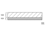
- FIG. 1 is a cross-sectional view showing an example of the structure of a lithium ion battery electrode 100 according to an embodiment of the present invention.
- the manufacturing method of the lithium ion battery electrode 100 according to this embodiment includes at least the following two steps (1) and (2). Thereby, the electrode for lithium ion batteries excellent in the external appearance can be obtained stably.
- Step of preparing an aqueous electrode slurry by the method for producing an aqueous electrode slurry for a lithium ion battery according to the present embodiment (2) Applying the obtained aqueous electrode slurry onto a substrate and drying the resulting aqueous medium Step of forming an electrode active material layer on the substrate by removing Step (1) is the same as the above-described method for producing the aqueous electrode slurry for lithium ion batteries according to the present embodiment, and the description thereof is omitted here. .
- the step (2) will be described.
- the aqueous electrode slurry obtained in the above step (1) is applied on the substrate 101 such as a current collector and dried to remove the aqueous medium.
- the electrode active material layer 103 By forming the electrode active material layer 103 on the base material 101, the electrode 100 for a lithium ion battery in which the electrode active material layer 103 is formed on the base material 101 is obtained.
- a generally known method can be used as a method for applying the aqueous electrode slurry onto the substrate 101.
- a generally known method can be used. Examples thereof include a reverse roll method, a direct roll method, a doctor blade method, a knife method, an extrusion method, a curtain method, a gravure method, a bar method, a dip method, and a squeeze method.
- the aqueous electrode slurry may be applied only on one side of the base material 101 or on both sides.
- the thickness, length and width of the coating layer can be appropriately determined according to the size of the battery.
- a method for drying the applied aqueous electrode slurry generally known methods can be used. For example, hot air, vacuum, infrared rays, far infrared rays, electron beams, and low temperature winds can be used alone or in combination.
- the drying temperature is, for example, in the range of 30 ° C. or higher and 350 ° C. or lower.
- the base material 101 used for manufacturing the lithium ion battery electrode 100 for example, an ordinary current collector that can be used for a lithium ion battery can be used.
- the negative electrode current collector copper, stainless steel, nickel, titanium, or an alloy thereof can be used, and among these, copper is particularly preferable.
- the positive electrode current collector aluminum, stainless steel, nickel, titanium, or an alloy thereof can be used, and among these, aluminum is particularly preferable.
- the shape of the current collector is not particularly limited. For example, a foil-like one having a thickness in the range of 0.001 to 0.5 mm can be used.
- the lithium ion battery electrode 100 according to the present embodiment may be pressed as necessary.
- a pressing method a generally known method can be used.
- a die press method, a calendar press method, etc. are mentioned.
- the pressing pressure is not particularly limited, but is, for example, in the range of 0.2 to 3 t / cm 2 .
- the thickness and density of the lithium ion battery electrode 100 according to the present embodiment are not particularly limited because they are appropriately determined according to the usage application of the battery, and can be set according to generally known information.
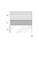
- FIG. 2 is a cross-sectional view showing an example of the structure of the lithium ion battery 150 according to the embodiment of the present invention.
- the lithium ion battery 150 according to the present embodiment includes at least a positive electrode 120, an electrolyte 110, and a negative electrode 130, and at least one of the positive electrode 120 and the negative electrode 130 includes the electrode 100 for a lithium ion battery according to the present embodiment.
- the lithium ion battery 150 according to the present embodiment may include a separator as necessary.
- the lithium ion battery 150 according to this embodiment can be manufactured according to a known method.
- a laminated body or a wound body can be used as the electrode.
- a metal exterior body or an aluminum laminate exterior body can be used as appropriate.
- the shape of the battery may be any shape such as a coin shape, a button shape, a sheet shape, a cylindrical shape, a square shape, and a flat shape.
- any known lithium salt may be used as the electrolyte in the battery electrolyte, and may be selected according to the type of active material.
- CF 3 Examples include SO 3 Li, CH 3 SO 3 Li, LiCF 3 SO 3 , LiC 4 F 9 SO 3 , Li (CF 3 SO 2 ) 2 N, and lower fatty acid carboxylate lithium.
- the solvent for dissolving the electrolyte is not particularly limited as long as it is usually used as a liquid component for dissolving the electrolyte.
- a porous separator As a separator, a porous separator is mentioned, for example.
- the separator include membranes, films, and nonwoven fabrics.
- the porous separator include polyolefin-based porous separators such as polypropylene and polyethylene; porous separators formed of polyvinylidene fluoride, polyethylene oxide, polyacrylonitrile, polyvinylidene fluoride hexafluoropropylene copolymer, etc. Is mentioned.
- Example 1 ⁇ Preparation of thickener powder A> First, a thickener aqueous solution having a concentration of 1.3% by mass was obtained by dissolving carboxymethyl cellulose powder (Sunrose (registered trademark) MAC series manufactured by Nippon Paper Industries Co., Ltd.) in 20 ° C. ion exchange water. Subsequently, the obtained thickener aqueous solution was filtered with a filter having an average pore diameter of 1 ⁇ m. Subsequently, thickener powder A was obtained by freeze-drying the thickener aqueous solution after filtration.
- carboxymethyl cellulose powder Unrose (registered trademark) MAC series manufactured by Nippon Paper Industries Co., Ltd.
- Step (C-1) To a planetary motion type planetary mixer, 960 g of graphite as a negative electrode active material, 10 g of thickener powder A, and 10 g of carbon black as a conductive auxiliary agent were charged. Next, dry mixing was performed at 20 ° C. for 60 minutes to obtain a powder mixture.
- Blending process (C-2-1) Next, water was added to the planetary motion type planetary mixer in which the step (C-1) was completed. Thereafter, wet mixing was performed for 2 minutes under the conditions of autorotation speed: 0.15 m / sec, revolution speed: 0.04 m / sec, and temperature: 20 ° C., so that the powder mixture was infiltrated with water.
- Solidification process (C-2-2) Next, wet mixing was performed for 40 minutes under the conditions of autorotation speed: 4.50 m / sec, revolution speed: 1.50 m / sec, temperature: 20 ° C. to obtain a slurry precursor.
- Step (C-3) an SBR aqueous solution having a solid content concentration of 40 mass% in which styrene butadiene rubber (SBR) was dispersed in water was prepared. 50 g of the obtained SBR aqueous solution was added to the planetary motion type planetary mixer in which the kneading step (C-2-2) was completed. Then, wet mixing was performed for 10 minutes under the conditions of rotation speed: 0.25 m / sec, revolution speed: 0.08 m / sec, temperature: 20 ° C. (5) Process (D) Subsequently, vacuum deaeration was performed to obtain an aqueous electrode slurry. The solid content concentration of the aqueous electrode slurry was adjusted to 50% by mass by adjusting the amount of water added in the conforming step (C-2-1).
- SBR styrene butadiene rubber
- aqueous electrode slurry was applied to one side of a copper foil as a current collector using a die coater and dried. Next, the obtained electrode was pressed to obtain a negative electrode.
- the viscosity of the aqueous thickener solution after being held for 3 days was measured at 25 ° C. and a shear rate of 3.4 s ⁇ 1 using a B-type viscometer. Thereafter, the rate of change in viscosity was calculated according to the following formula, and the storage stability of the thickener aqueous solution was evaluated according to the following criteria.
- Viscosity change rate [%] 100 ⁇ (viscosity after 3 days holding) / (viscosity before 3 days holding) ⁇ : Viscosity change rate is 80% or more and less than 120% ⁇ : Viscosity change rate is 120% or more and less than 150% or 50% or more and less than 80% ⁇ : Viscosity change rate is 150% or more or 10% or more and less than 50%
- Viscosity change rate [%] 100 ⁇ (viscosity after 3 days holding) / (viscosity before 3 days holding) ⁇ : Viscosity change rate is 80% or more and less than 120% ⁇ : Viscosity change rate is 120% or more and less than 150% or 50% or more and less than 80% ⁇ : Viscosity change rate is 150% or more or 10% or more and less than 50% ⁇ : above Aqueous electrode slurry separated by holding test (judged by visual inspection) The obtained results are shown in Table 1.
- the viscosity variation of the aqueous electrode slurry was evaluated as follows. First, five aqueous electrode slurries with the same conditions were prepared as samples. Next, for the obtained aqueous electrode slurry, the viscosity at 25 ° C. and a shear rate of 3.4 s ⁇ 1 was measured using a B-type viscometer, the maximum variation was calculated by the following formula, and the aqueous electrode slurry was calculated according to the following criteria: The variation of each lot was evaluated.
- Maximum variation (mPa ⁇ s) (maximum viscosity among 5 samples) ⁇ (minimum viscosity among 5 samples) ⁇ : Maximum variation is less than 500 mPa ⁇ s ⁇ : Maximum variation is 500 mPa ⁇ s or more and less than 1000 mPa ⁇ s ⁇ : Maximum variation is 1000 mPa ⁇ s or more
- Example appearance evaluation of negative electrode The obtained negative electrode surface was observed at a magnification of 100 times using an optical microscope, and the presence or absence of aggregates was examined at any five locations on the negative electrode surface. Next, the negative electrode appearance was evaluated according to the following criteria. A: Aggregates were not observed in all five places, and the visual appearance was good. A: Although one aggregate was observed in total, the visual appearance was good. X: Two or more aggregates were observed in total, and the visual appearance was poor.
- Example 2 Thickener powder A under the same conditions as in Example 1 except that the average pore size of the filter when producing thickener powder A was changed and the content of the water-insoluble component was changed to the values shown in Table 1.
- a thickener aqueous solution, a water-based electrode slurry, and a negative electrode were prepared and evaluated. The obtained results are shown in Table 1.
- Example 1 A thickener aqueous solution, an aqueous electrode slurry, and a negative electrode were used under the same conditions as in Example 1 except that carboxymethyl cellulose powder (MAC series of Sunrose (registered trademark) manufactured by Nippon Paper Industries Co., Ltd.) was used as it was instead of the thickener powder A. Were made and each evaluation was performed. The obtained results are shown in Table 1.
- carboxymethyl cellulose powder MAC series of Sunrose (registered trademark) manufactured by Nippon Paper Industries Co., Ltd.
- Step 1 Into a planetary motion type planetary mixer, 960 g of graphite as a negative electrode active material and 10 g of carbon black as a conductive additive were charged. Next, dry mixing was performed at 20 ° C. for 60 minutes to obtain a powder mixture.
- Step 2 Subsequently, water and the thickener aqueous solution B were added to the planetary motion type planetary mixer in which the above step 1 was completed. Thereafter, wet mixing was performed for 2 minutes under the conditions of autorotation speed: 0.15 m / sec, revolution speed: 0.04 m / sec, and temperature: 20 ° C., so that the powder mixture was infiltrated with water.
- Step 4 an SBR aqueous solution having a solid content concentration of 40 mass% in which styrene butadiene rubber (SBR) was dispersed in water was prepared. 50 g of the obtained SBR aqueous solution and thickener aqueous solution B were added to the planetary motion type planetary mixer in which Step 3 was completed. The total amount of thickener powder contained in the thickener aqueous solution B used in Steps 2 to 4 was 10 g. Then, wet mixing was performed for 10 minutes under the conditions of rotation speed: 0.25 m / sec, revolution speed: 0.08 m / sec, temperature: 20 ° C. (5) Process 5 Subsequently, vacuum deaeration was performed to obtain an aqueous electrode slurry. The solid content concentration of the aqueous electrode slurry was adjusted to 50% by mass by adjusting the amount of water added in each step.
- SBR styrene butadiene rubber
- aqueous electrode slurry was applied to one side of a copper foil as a current collector using a die coater and dried. Next, the obtained negative electrode was pressed to obtain a negative electrode.
Landscapes
- Chemical & Material Sciences (AREA)
- Engineering & Computer Science (AREA)
- Chemical Kinetics & Catalysis (AREA)
- Electrochemistry (AREA)
- General Chemical & Material Sciences (AREA)
- Materials Engineering (AREA)
- Organic Chemistry (AREA)
- Manufacturing & Machinery (AREA)
- Battery Electrode And Active Subsutance (AREA)
Abstract
本発明のリチウムイオン電池用増粘剤粉末は、リチウムイオン電池用の水系電極スラリーの増粘に用いられる増粘剤粉末であって、セルロース系水溶性高分子を含み、下記条件1により算出される当該増粘剤粉末中の水不溶解成分の含有量が1.0質量%以下である。 (条件1:当該増粘剤粉末を水に溶解させ、濃度1.3質量%の増粘剤水溶液を得る。次いで、上記増粘剤水溶液を平均孔径1μmのフィルターでろ過する。次いで、上記フィルター上に残された上記水不溶解成分を乾燥し、上記水不溶解成分の質量を測る。次いで、当該増粘剤粉末中の水不溶解成分の含有量を算出する。)
Description
本発明は、リチウムイオン電池用増粘剤粉末、水系電極スラリー、リチウムイオン電池用電極、リチウムイオン電池、リチウムイオン電池用水系電極スラリーの製造方法およびリチウムイオン電池用電極の製造方法に関する。
リチウムイオン電池に用いられる電極は、一般的に、電極活物質層と集電体から主に構成されている。電極活物質層は、例えば、電極活物質、増粘剤および水系バインダー等を含む水系電極スラリーを金属箔等の集電体表面に塗布して乾燥することにより得られる。
リチウムイオン電池用電極の製造方法としては、例えば、特許文献1および特許文献2に記載の方法が挙げられる。
特許文献1(特開2006-24550号公報)には、活物質A、導電材B、結着材Cおよび増粘剤Dを含む合剤と、増粘剤Dを溶解する液状成分Eとを含み、導電材Bが少なくとも炭素材料からなり、増粘剤Dが少なくとも水溶性高分子からなり、液状成分Eが少なくとも水からなる合剤塗料を調製する工程aと、合剤塗料を集電体上に塗布する工程bとを有し、合剤塗料を調製する工程aが、活物質A、導電材Bおよび粉末状態の増粘剤Dを含む配合物を、液状成分Eとともに混練して、一次混練物を得る一次混練工程と、一次混練物を、結着材Cおよび追加の液状成分とともに混練して、二次混練物を得る二次混練工程とを有する非水系二次電池の正極用電極板の製造法が記載されている。
特許文献2(特開2006-107896号公報)には、黒鉛を主剤とする炭素材料、増粘剤、および結着材を混練分散することにより構成されるペーストを用いる非水系二次電池の負極用電極板の製造方法において、黒鉛は鉄の含有量が500ppm以下であり、増粘剤はカルボキシル基を含む水溶性高分子であり、結着材は極性基を有する水分散性高分子であり、負極塗膜形成用のペーストの混練工程は、少なくとも黒鉛に増粘剤を粉末状態で添加し、分散媒と共に混練する初混練工程と、初混練工程の混練物を分散媒で希釈し混練する希釈混練工程と、希釈混練工程の混練物に結着材を添加し、混練することによりペーストを作成する仕上げ混練工程の3つの工程を含み、初混練工程における混練の剪断力が、希釈混練工程および仕上げ混練工程における混練の剪断力の2.5倍以上であることを特徴とする非水系二次電池の負極用電極板の製造方法が記載されている。
本発明者らの検討によれば、特許文献1および2に記載されているような製造方法により得られた水系電極スラリーはロットごとに粘度のバラつきがあったり、保存時に粘度が変化したりして、品質が安定しない場合があることが明らかになった。また、このような品質が安定しない水系電極スラリーを用いて作製した電極には凝集物が発生しやすいことが明らかになった。
さらに、本発明者らの検討によれば、水系電極スラリーの調製の際に、増粘剤水溶液を分割して添加する方法により得られた水系電極スラリーもロットごとに粘度のバラつきがあったり、保存時に粘度が変化したりして、品質が安定しない場合があることが明らかになった。
すなわち、本発明者らの検討によれば、従来の水系電極スラリーは品質安定性に劣っていることが明らかになった。
さらに、本発明者らの検討によれば、水系電極スラリーの調製の際に、増粘剤水溶液を分割して添加する方法により得られた水系電極スラリーもロットごとに粘度のバラつきがあったり、保存時に粘度が変化したりして、品質が安定しない場合があることが明らかになった。
すなわち、本発明者らの検討によれば、従来の水系電極スラリーは品質安定性に劣っていることが明らかになった。
本発明は上記事情に鑑みてなされたものであり、品質安定性に優れた水系電極スラリーを安定的に得ることが可能なリチウムイオン電池用増粘剤粉末、品質安定性に優れた水系電極スラリー、外観に優れたリチウムイオン電池用電極およびその電極を用いたリチウムイオン電池を提供するものである。
本発明者らは上記課題を達成すべく鋭意検討を重ねた。その結果、特定の条件により算出される増粘剤粉末中の水不溶解成分の含有量という尺度が、品質安定性に優れた水系電極スラリーを安定的に得るための設計指針として有効であることを見出して本発明を完成するに至った。
本発明によれば、
リチウムイオン電池用の水系電極スラリーの増粘に用いられる増粘剤粉末であって、
セルロース系水溶性高分子を含み、
下記条件1により算出される当該増粘剤粉末中の水不溶解成分の含有量が、1.0質量%以下であるリチウムイオン電池用増粘剤粉末が提供される。
(条件1:当該増粘剤粉末を水に溶解させ、濃度1.3質量%の増粘剤水溶液を得る。次いで、上記増粘剤水溶液を平均孔径1μmのフィルターでろ過する。次いで、上記フィルター上に残された上記水不溶解成分を乾燥し、上記水不溶解成分の質量を測る。次いで、当該増粘剤粉末中の水不溶解成分の含有量を算出する。)
リチウムイオン電池用の水系電極スラリーの増粘に用いられる増粘剤粉末であって、
セルロース系水溶性高分子を含み、
下記条件1により算出される当該増粘剤粉末中の水不溶解成分の含有量が、1.0質量%以下であるリチウムイオン電池用増粘剤粉末が提供される。
(条件1:当該増粘剤粉末を水に溶解させ、濃度1.3質量%の増粘剤水溶液を得る。次いで、上記増粘剤水溶液を平均孔径1μmのフィルターでろ過する。次いで、上記フィルター上に残された上記水不溶解成分を乾燥し、上記水不溶解成分の質量を測る。次いで、当該増粘剤粉末中の水不溶解成分の含有量を算出する。)
また、本発明によれば、
正極活物質および負極活物質から選択される電極活物質と、
水系バインダーと、
上記リチウムイオン電池用増粘剤粉末と、
水系媒体と、
を含み、
上記リチウムイオン電池用増粘剤粉末は上記水系媒体に溶解している水系電極スラリーが提供される。
正極活物質および負極活物質から選択される電極活物質と、
水系バインダーと、
上記リチウムイオン電池用増粘剤粉末と、
水系媒体と、
を含み、
上記リチウムイオン電池用増粘剤粉末は上記水系媒体に溶解している水系電極スラリーが提供される。
また、本発明によれば、
正極活物質および負極活物質から選択される電極活物質と、
水系バインダーと、
上記リチウムイオン電池用増粘剤粉末と、
を含むリチウムイオン電池用電極が提供される。
正極活物質および負極活物質から選択される電極活物質と、
水系バインダーと、
上記リチウムイオン電池用増粘剤粉末と、
を含むリチウムイオン電池用電極が提供される。
また、本発明によれば、
正極と、電解質と、負極とを少なくとも備えたリチウムイオン電池であって、
上記正極および上記負極の少なくとも一方が上記リチウムイオン電池用電極を含むリチウムイオン電池が提供される。
正極と、電解質と、負極とを少なくとも備えたリチウムイオン電池であって、
上記正極および上記負極の少なくとも一方が上記リチウムイオン電池用電極を含むリチウムイオン電池が提供される。
また、本発明によれば、
正極活物質および負極活物質から選択される電極活物質と、水系バインダーと、増粘剤と、水系媒体と、を含むリチウムイオン電池用水系電極スラリーの製造方法であって、
増粘剤水溶液をフィルターでろ過する工程と、
ろ過後の上記増粘剤水溶液を乾燥することにより増粘剤粉末を得る工程と、
電極活物質、水系バインダー、得られた上記増粘剤粉末および水系媒体を混合することにより水系電極スラリーを調製する工程と、
を含むリチウムイオン電池用水系電極スラリーの製造方法が提供される。
正極活物質および負極活物質から選択される電極活物質と、水系バインダーと、増粘剤と、水系媒体と、を含むリチウムイオン電池用水系電極スラリーの製造方法であって、
増粘剤水溶液をフィルターでろ過する工程と、
ろ過後の上記増粘剤水溶液を乾燥することにより増粘剤粉末を得る工程と、
電極活物質、水系バインダー、得られた上記増粘剤粉末および水系媒体を混合することにより水系電極スラリーを調製する工程と、
を含むリチウムイオン電池用水系電極スラリーの製造方法が提供される。
また、本発明によれば、
上記リチウムイオン電池用水系電極スラリーの製造方法により水系電極スラリーを調製する工程と、
得られた上記水系電極スラリーを基材上に塗工して乾燥し、上記水系媒体を除去することにより上記基材上に電極活物質層を形成する工程と、
を含むリチウムイオン電池用電極の製造方法が提供される。
上記リチウムイオン電池用水系電極スラリーの製造方法により水系電極スラリーを調製する工程と、
得られた上記水系電極スラリーを基材上に塗工して乾燥し、上記水系媒体を除去することにより上記基材上に電極活物質層を形成する工程と、
を含むリチウムイオン電池用電極の製造方法が提供される。
本発明によれば、品質安定性に優れた水系電極スラリーを安定的に得ることが可能なリチウムイオン電池用増粘剤粉末、品質安定性に優れた水系電極スラリー、外観に優れたリチウムイオン電池用電極およびその電極を用いたリチウムイオン電池を提供することができる。
上述した目的、およびその他の目的、特徴および利点は、以下に述べる好適な実施の形態、およびそれに付随する以下の図面によってさらに明らかになる。
以下に、本発明の実施形態について、図面を用いて説明する。なお、すべての図面において、同様な構成要素には同様の符号を付し、適宜説明を省略する。また、図において各構成要素は本発明が理解できる程度の形状、大きさおよび配置関係を概略的に示したものであり、実寸とは異なっている。
なお、本実施形態では数値範囲の「A~B」は特に断りがなければ、A以上B以下を表す。
なお、本実施形態では数値範囲の「A~B」は特に断りがなければ、A以上B以下を表す。
<リチウムイオン電池用増粘剤粉末(p)>
本実施形態に係るリチウムイオン電池用増粘剤粉末(p)はリチウムイオン電池用の水系電極スラリーの増粘に用いられる増粘剤粉末であって、セルロース系水溶性高分子を含み、下記条件1により算出される増粘剤粉末(p)中の水不溶解成分の含有量が1.0質量%以下、好ましくは0.8質量%以下、より好ましくは0.5質量%以下、さらに好ましくは0.3質量%以下、さらにより好ましくは0.1質量%以下、特に好ましくは0.08質量%以下である。また、増粘剤粉末(p)中の水不溶解成分の含有量は好ましくは0.01質量%以上、より好ましくは0.02質量%以上、さらに好ましくは0.04質量%以上、さらにより好ましくは0.06質量%以上である。
条件1:当該増粘剤粉末を水に溶解させ、濃度1.3質量%の増粘剤水溶液を得る。次いで、増粘剤水溶液を平均孔径1μmのフィルターでろ過する。次いで、フィルター上に残された水不溶解成分を乾燥し、水不溶解成分の質量を測る。次いで、増粘剤粉末(p)中の水不溶解成分の含有量を算出する。
本実施形態に係るリチウムイオン電池用増粘剤粉末(p)はリチウムイオン電池用の水系電極スラリーの増粘に用いられる増粘剤粉末であって、セルロース系水溶性高分子を含み、下記条件1により算出される増粘剤粉末(p)中の水不溶解成分の含有量が1.0質量%以下、好ましくは0.8質量%以下、より好ましくは0.5質量%以下、さらに好ましくは0.3質量%以下、さらにより好ましくは0.1質量%以下、特に好ましくは0.08質量%以下である。また、増粘剤粉末(p)中の水不溶解成分の含有量は好ましくは0.01質量%以上、より好ましくは0.02質量%以上、さらに好ましくは0.04質量%以上、さらにより好ましくは0.06質量%以上である。
条件1:当該増粘剤粉末を水に溶解させ、濃度1.3質量%の増粘剤水溶液を得る。次いで、増粘剤水溶液を平均孔径1μmのフィルターでろ過する。次いで、フィルター上に残された水不溶解成分を乾燥し、水不溶解成分の質量を測る。次いで、増粘剤粉末(p)中の水不溶解成分の含有量を算出する。
本発明者らの検討によれば、特許文献1および2に記載されているような製造方法により得られた水系電極スラリーはロットごとに粘度のバラつきがあったり、保存時に粘度が変化したりして、品質が安定しない場合があることが明らかになった。また、このような品質が安定しない水系電極スラリーを用いて作製した電極には凝集物が発生しやすいことが明らかになった。
さらに、本発明者らの検討によれば、水系電極スラリーの調製の際に、増粘剤水溶液を分割して添加する方法により得られた水系電極スラリーもロットごとに粘度のバラつきがあったり、保存時に粘度が変化したりして、品質が安定しない場合があることが明らかになった。
すなわち、本発明者らの検討によれば、従来の水系電極スラリーは品質安定性に劣っていることが明らかになった。
さらに、本発明者らの検討によれば、水系電極スラリーの調製の際に、増粘剤水溶液を分割して添加する方法により得られた水系電極スラリーもロットごとに粘度のバラつきがあったり、保存時に粘度が変化したりして、品質が安定しない場合があることが明らかになった。
すなわち、本発明者らの検討によれば、従来の水系電極スラリーは品質安定性に劣っていることが明らかになった。
本発明者らは上記課題を達成すべく鋭意検討を重ねた。その結果、従来用いていた増粘剤粉末には水不溶解成分が含まれており、この水不溶解成分を特定量含むと得られる水系電極スラリーの品質安定性が低下することが明らかになった。
また、増粘剤水溶液を分割して添加する方法では、固練り工程の後にも増粘剤水溶液を添加するため、水系電極スラリーの品質安定性が低下することが明らかになった。
そこで、本発明者は、さらに鋭意検討した。その結果、上記条件1により算出される水不溶解成分の含有量が上記上限値以下である増粘剤粉末(p)を用いると、品質安定性に優れた増粘剤水溶液および水系電極スラリーを安定的に得ることができることを見出した。そして、このようにして得られた水系電極スラリーを用いると、凝集物の発生が抑制され、外観に優れたリチウムイオン電池用電極を安定的に得ることができることを見出した。
すなわち、上記条件1により算出される水不溶解成分の含有量が上記上限値以下である本実施形態に係る増粘剤粉末(p)を用いることにより、品質安定性に優れた水系電極スラリーを安定的に得ることができる。そして、このような水系電極スラリーを用いることにより、外観に優れたリチウムイオン電池用電極を安定的に得ることができる。
また、増粘剤水溶液を分割して添加する方法では、固練り工程の後にも増粘剤水溶液を添加するため、水系電極スラリーの品質安定性が低下することが明らかになった。
そこで、本発明者は、さらに鋭意検討した。その結果、上記条件1により算出される水不溶解成分の含有量が上記上限値以下である増粘剤粉末(p)を用いると、品質安定性に優れた増粘剤水溶液および水系電極スラリーを安定的に得ることができることを見出した。そして、このようにして得られた水系電極スラリーを用いると、凝集物の発生が抑制され、外観に優れたリチウムイオン電池用電極を安定的に得ることができることを見出した。
すなわち、上記条件1により算出される水不溶解成分の含有量が上記上限値以下である本実施形態に係る増粘剤粉末(p)を用いることにより、品質安定性に優れた水系電極スラリーを安定的に得ることができる。そして、このような水系電極スラリーを用いることにより、外観に優れたリチウムイオン電池用電極を安定的に得ることができる。
増粘剤粉末(p)はセルロース系水溶性高分子を主成分として含む。ここで、セルロース系水溶性高分子を主成分として含むとは、増粘剤粉末(p)がセルロース系水溶性高分子を50質量%以上含むことを意味する。増粘剤粉末(p)はセルロース系水溶性高分子を好ましくは70質量%以上、より好ましくは90質量%以上、特に好ましくは99質量%以上含む。
セルロース系水溶性高分子としては水系電極スラリーの塗工性を向上させるものであれば特に限定されない。セルロース系水溶性高分子としては、例えば、カルボキシメチルセルロース、ヒドロキシメチルセルロース、ヒドロキシエチルセルロース、メチルエチルヒドロキシセルロース、メチルセルロース、ヒドロキシプロピルセルロース等のセルロース系ポリマー、およびこれらのセルロース系ポリマーのアンモニウム塩並びにアルカリ金属塩等のセルロース系ポリマー塩等から選択される一種または二種以上を用いることができる。
これらの中でもカルボキシメチルセルロースおよびカルボキシメチルセルロース塩から選択される少なくとも一種を含むことが好ましく、カルボキシメチルセルロース、カルボキシメチルセルロースのアンモニウム塩、カルボキシメチルセルロースのナトリウム塩およびカルボキシメチルセルロースのカリウム塩から選択される一種または二種以上を含むことがより好ましい。
セルロース系水溶性高分子としては水系電極スラリーの塗工性を向上させるものであれば特に限定されない。セルロース系水溶性高分子としては、例えば、カルボキシメチルセルロース、ヒドロキシメチルセルロース、ヒドロキシエチルセルロース、メチルエチルヒドロキシセルロース、メチルセルロース、ヒドロキシプロピルセルロース等のセルロース系ポリマー、およびこれらのセルロース系ポリマーのアンモニウム塩並びにアルカリ金属塩等のセルロース系ポリマー塩等から選択される一種または二種以上を用いることができる。
これらの中でもカルボキシメチルセルロースおよびカルボキシメチルセルロース塩から選択される少なくとも一種を含むことが好ましく、カルボキシメチルセルロース、カルボキシメチルセルロースのアンモニウム塩、カルボキシメチルセルロースのナトリウム塩およびカルボキシメチルセルロースのカリウム塩から選択される一種または二種以上を含むことがより好ましい。
本実施形態に係るリチウムイオン電池用増粘剤粉末(p)において、上記水不溶解成分は特に限定されないが、例えば、上記セルロース系水溶性高分子由来の繊維成分を含んでいる。
本実施形態に係るリチウムイオン電池用増粘剤粉末(p)において、下記条件2により算出される粘度が10mPa・s以上20000mPa・s以下であることが好ましく、100mPa・s以上10000mPa・s以下であることがより好ましく、1000mPa・s以上8000mPa・s以下であることがさらに好ましく、2000mPa・s以上4000mPa・s以下であることが特に好ましい。
条件2:増粘剤粉末(p)を水に溶解させ、濃度1.3質量%の増粘剤水溶液を得る。次いで、B型粘度計を用いて、25℃、せん断速度3.4s-1の条件で増粘剤水溶液の粘度を測る。
これにより、得られる水系電極スラリーの塗工性をより一層向上させることができる。
条件2:増粘剤粉末(p)を水に溶解させ、濃度1.3質量%の増粘剤水溶液を得る。次いで、B型粘度計を用いて、25℃、せん断速度3.4s-1の条件で増粘剤水溶液の粘度を測る。
これにより、得られる水系電極スラリーの塗工性をより一層向上させることができる。
<増粘剤粉末(p)の製造方法>
次に、本実施形態に係るリチウムイオン電池用増粘剤粉末(p)の製造方法を説明する。
本実施形態に係る増粘剤粉末(p)は、例えば、以下の工程(A)および工程(B)を少なくとも含む製造方法により得ることができる。ただし、本実施形態に係るリチウムイオン電池用増粘剤粉末(p)の製造方法は、以下の例に限定されない。
工程(A):増粘剤水溶液をフィルターでろ過する工程
工程(B):ろ過後の増粘剤水溶液を乾燥することにより増粘剤粉末(p)を得る工程
次に、本実施形態に係るリチウムイオン電池用増粘剤粉末(p)の製造方法を説明する。
本実施形態に係る増粘剤粉末(p)は、例えば、以下の工程(A)および工程(B)を少なくとも含む製造方法により得ることができる。ただし、本実施形態に係るリチウムイオン電池用増粘剤粉末(p)の製造方法は、以下の例に限定されない。
工程(A):増粘剤水溶液をフィルターでろ過する工程
工程(B):ろ過後の増粘剤水溶液を乾燥することにより増粘剤粉末(p)を得る工程
はじめに、増粘剤粉末を水系媒体に溶解させることにより増粘剤水溶液を得る。ここで、増粘剤粉末は公知の方法で製造することもできるが、種々の市販品を用いることもできる。また、市販の増粘剤水溶液を用いてもよい。
増粘剤粉末を溶解させる水系媒体については特に限定されず、例えば、蒸留水、イオン交換水、市水、工業用水等を使用できる。これらの中でも、蒸留水やイオン交換水が好ましい。また、水には、アルコール等の水と親水性の高い溶媒を混合させてもよい。
増粘剤水溶液の増粘剤濃度は特に限定されないが、例えば、0.1~10質量%、好ましくは0.5~5質量%である。
増粘剤粉末を水系媒体に溶解させる方法は特に限定されず、公知の方法を採用することができる。
増粘剤粉末を溶解させる水系媒体については特に限定されず、例えば、蒸留水、イオン交換水、市水、工業用水等を使用できる。これらの中でも、蒸留水やイオン交換水が好ましい。また、水には、アルコール等の水と親水性の高い溶媒を混合させてもよい。
増粘剤水溶液の増粘剤濃度は特に限定されないが、例えば、0.1~10質量%、好ましくは0.5~5質量%である。
増粘剤粉末を水系媒体に溶解させる方法は特に限定されず、公知の方法を採用することができる。
次いで、得られた増粘剤水溶液をフィルターでろ過する。フィルターの平均孔径は特に限定されないが、例えば、好ましくは0.1~5μm、より好ましくは0.2~3μmである。これにより水不溶解成分を効果的に除去することができ、水不溶解成分の含有量が上記上限値以下の増粘剤粉末(p)を効率的に得ることができる。
次いで、ろ過後の増粘剤水溶液を乾燥することにより増粘剤粉末(p)を得る。増粘剤水溶液の乾燥方法としては特に限定されないが、例えば、低温下で増粘剤水溶液を乾燥する凍結乾燥法や、噴霧乾燥法を用いることができる。
これにより、増粘剤水溶液から増粘剤を粉末状に乾燥することができ、本実施形態に係る増粘剤粉末(p)をより効率的に得ることができる。
これにより、増粘剤水溶液から増粘剤を粉末状に乾燥することができ、本実施形態に係る増粘剤粉末(p)をより効率的に得ることができる。
<水系電極スラリー>
次に、本実施形態に係る水系電極スラリーについて説明する。
本実施形態に係る水系電極スラリーは、正極活物質および負極活物質から選択される電極活物質(a)と、水系バインダー(b)と、本実施形態に係るリチウムイオン電池用増粘剤粉末(p)と、水系媒体(c)と、を含み、リチウムイオン電池用増粘剤粉末(p)は水系媒体(c)に溶解している。また、本実施形態に係る水系電極スラリーは、得られる電極の電子伝導性を向上させる観点から、導電助剤(d)をさらに含むことが好ましい。
ここで、本実施形態に係る水系電極スラリーにおいて、リチウムイオン電池用増粘剤粉末(p)は水系電極スラリー中に溶解しており、粉末状態ではない。
次に、本実施形態に係る水系電極スラリーについて説明する。
本実施形態に係る水系電極スラリーは、正極活物質および負極活物質から選択される電極活物質(a)と、水系バインダー(b)と、本実施形態に係るリチウムイオン電池用増粘剤粉末(p)と、水系媒体(c)と、を含み、リチウムイオン電池用増粘剤粉末(p)は水系媒体(c)に溶解している。また、本実施形態に係る水系電極スラリーは、得られる電極の電子伝導性を向上させる観点から、導電助剤(d)をさらに含むことが好ましい。
ここで、本実施形態に係る水系電極スラリーにおいて、リチウムイオン電池用増粘剤粉末(p)は水系電極スラリー中に溶解しており、粉末状態ではない。
(電極活物質(a))
本実施形態に係る電極活物質(a)は用途に応じて適宜選択される。正極を作製するときは正極活物質を使用し、負極を作製するときは負極活物質を使用する。
本実施形態に係る電極活物質(a)は用途に応じて適宜選択される。正極を作製するときは正極活物質を使用し、負極を作製するときは負極活物質を使用する。
正極活物質としてはリチウムイオン電池の正極に使用可能な通常の正極活物質であれば特に限定されない。例えば、リチウムニッケル複合酸化物、リチウムコバルト複合酸化物、リチウムマンガン複合酸化物、リチウム-マンガン-ニッケル複合酸化物等のリチウムと遷移金属との複合酸化物;TiS2、FeS、MoS2等の遷移金属硫化物;MnO、V2O5、V6O13、TiO2等の遷移金属酸化物、オリビン型リチウムリン酸化物等が挙げられる。
オリビン型リチウムリン酸化物は、例えば、Mn、Cr、Co、Cu、Ni、V、Mo、Ti、Zn、Al、Ga、Mg、B、Nb、およびFeよりなる群のうちの少なくとも1種の元素と、リチウムと、リンと、酸素とを含んでいる。これらの化合物はその特性を向上させるために一部の元素を部分的に他の元素に置換したものであってもよい。
オリビン型リチウムリン酸化物は、例えば、Mn、Cr、Co、Cu、Ni、V、Mo、Ti、Zn、Al、Ga、Mg、B、Nb、およびFeよりなる群のうちの少なくとも1種の元素と、リチウムと、リンと、酸素とを含んでいる。これらの化合物はその特性を向上させるために一部の元素を部分的に他の元素に置換したものであってもよい。
これらの中でも、オリビン型リチウム鉄リン酸化物、リチウムコバルト複合酸化物、リチウムニッケル複合酸化物、リチウムマンガン複合酸化物、リチウム-マンガン-ニッケル複合酸化物が好ましい。これらの正極活物質は作用電位が高いことに加えて容量も大きく、大きなエネルギー密度を有する。
正極活物質は1種単独で使用してもよいし、2種以上を組み合わせて使用してもよい。
正極活物質は1種単独で使用してもよいし、2種以上を組み合わせて使用してもよい。
負極活物質としては、リチウムイオン電池の負極に使用可能な通常の負極活物質であれば特に限定されない。例えば、天然黒鉛、人造黒鉛、樹脂炭、炭素繊維、活性炭、ハードカーボン、ソフトカーボン等の炭素材料;リチウム金属、リチウム合金等のリチウム系金属;シリコン、スズ等の金属;ポリアセン、ポリアセチレン、ポリピロール等の導電性ポリマー等が挙げられる。これらの中でも炭素材料が好ましく、特に天然黒鉛や人造黒鉛等の黒鉛質材料が好ましい。
負極活物質は1種単独で使用してもよいし、2種以上を組み合わせて使用してもよい。
負極活物質は1種単独で使用してもよいし、2種以上を組み合わせて使用してもよい。
電極活物質(a)の含有量は、水系電極スラリーの固形分の全量を100質量部としたとき、70質量部以上99.97質量部以下であることが好ましく、85質量部以上99.85質量部以下であることがより好ましい。
(水系バインダー(b))
水系バインダー(b)は、電極成形が可能であり、十分な電気化学的安定性を有していれば特に限定されないが、例えば、ポリアクリル酸、ポリテトラフルオロエチレン、ポリフッ化ビニリデン、スチレンブタジエンゴム、ポリイミド等が挙げられる。これらの水系バインダー(b)は一種単独で用いてもよく、二種以上を組み合わせて用いてもよい。これらの中でも、スチレンブタジエンゴムが好ましい。
なお、本実施形態において、水系バインダー(b)とは、水系媒体に分散し、エマルジョン水溶液を形成できるものをいう。
水系バインダー(b)は、電極成形が可能であり、十分な電気化学的安定性を有していれば特に限定されないが、例えば、ポリアクリル酸、ポリテトラフルオロエチレン、ポリフッ化ビニリデン、スチレンブタジエンゴム、ポリイミド等が挙げられる。これらの水系バインダー(b)は一種単独で用いてもよく、二種以上を組み合わせて用いてもよい。これらの中でも、スチレンブタジエンゴムが好ましい。
なお、本実施形態において、水系バインダー(b)とは、水系媒体に分散し、エマルジョン水溶液を形成できるものをいう。
水系バインダー(b)の含有量は、水系電極スラリーの固形分の全量を100質量部としたとき、0.01質量部以上10.0質量部以下であることが好ましく、0.05質量部以上5.0質量部以下であることがより好ましい。水系バインダー(b)の含有量が上記範囲内であると、水系電極スラリーの塗工性、バインダーの結着性および電池特性のバランスがより一層優れる。
水系バインダー(b)は、粉末状のものを水系媒体に分散させてエマルジョン水溶液として用いる。これにより、電極活物質(a)間や導電助剤(d)間、電極活物質(a)と導電助剤(d)との間との接触を阻害せず、水系バインダー(b)の分散性を向上させることができる。
水系バインダー(b)を分散させる水系媒体については、水系バインダー(b)を分散できるものであれば特に限定されないが、蒸留水、イオン交換水、市水、工業用水等を使用できる。これらの中でも、蒸留水やイオン交換水が好ましい。また、水には、アルコール等の水と親水性の高い溶媒を混合させてもよい。
水系バインダー(b)を分散させる水系媒体については、水系バインダー(b)を分散できるものであれば特に限定されないが、蒸留水、イオン交換水、市水、工業用水等を使用できる。これらの中でも、蒸留水やイオン交換水が好ましい。また、水には、アルコール等の水と親水性の高い溶媒を混合させてもよい。
(増粘剤粉末(p))
増粘剤粉末(p)は、本実施形態に係る増粘剤粉末(p)を用いることができる。
増粘剤粉末(p)は1種単独で使用してもよいし、2種以上を組み合わせて使用してもよい。増粘剤粉末(p)の含有量は、水系電極スラリーの固形分の全量を100質量部としたとき、0.01質量部以上10.0質量部以下であることが好ましく、0.05質量部以上5.0質量部以下であることがより好ましい。増粘剤粉末(p)の含有量が上記範囲内であると、水系電極スラリーの塗工性、バインダーの結着性および電池特性のバランスがより一層優れる。
増粘剤粉末(p)は、本実施形態に係る増粘剤粉末(p)を用いることができる。
増粘剤粉末(p)は1種単独で使用してもよいし、2種以上を組み合わせて使用してもよい。増粘剤粉末(p)の含有量は、水系電極スラリーの固形分の全量を100質量部としたとき、0.01質量部以上10.0質量部以下であることが好ましく、0.05質量部以上5.0質量部以下であることがより好ましい。増粘剤粉末(p)の含有量が上記範囲内であると、水系電極スラリーの塗工性、バインダーの結着性および電池特性のバランスがより一層優れる。
(水系媒体(c))
本実施形態に係る水系媒体(c)については特に限定されず、例えば、蒸留水、イオン交換水、市水、工業用水等を使用できる。これらの中でも、蒸留水やイオン交換水が好ましい。また、水には、アルコール等の水と親水性の高い溶媒を混合させてもよい。
本実施形態に係る水系媒体(c)については特に限定されず、例えば、蒸留水、イオン交換水、市水、工業用水等を使用できる。これらの中でも、蒸留水やイオン交換水が好ましい。また、水には、アルコール等の水と親水性の高い溶媒を混合させてもよい。
(導電助剤(d))
本実施形態に係る水系電極スラリーは、得られる電極の電子伝導性を向上させる観点から、導電助剤(d)をさらに含むことが好ましい。
導電助剤(d)は、電子伝導性を有しており、電極の導電性を向上させるものであれば特に限定されない。本実施形態に係る導電助剤(d)として、例えば、アセチレンブラック、ケッチェンブラック、カーボンブラック、カーボンナノファイバー、活物質として使用される黒鉛よりも粒子径の小さい黒鉛等の炭素材料が挙げられる。これらの導電助剤(d)は1種単独で使用してもよいし、2種以上を組み合わせて使用してもよい。
本実施形態に係る水系電極スラリーは、得られる電極の電子伝導性を向上させる観点から、導電助剤(d)をさらに含むことが好ましい。
導電助剤(d)は、電子伝導性を有しており、電極の導電性を向上させるものであれば特に限定されない。本実施形態に係る導電助剤(d)として、例えば、アセチレンブラック、ケッチェンブラック、カーボンブラック、カーボンナノファイバー、活物質として使用される黒鉛よりも粒子径の小さい黒鉛等の炭素材料が挙げられる。これらの導電助剤(d)は1種単独で使用してもよいし、2種以上を組み合わせて使用してもよい。
導電助剤(d)の含有量は、水系電極スラリーの固形分の全量を100質量部としたとき、0.01質量部以上10.0質量部以下であることが好ましく、0.05質量部以上5.0質量部以下であることがより好ましい。
導電助剤(d)の含有量が上記範囲内であると、水系電極スラリーの塗工性およびバインダーの結着性のバランスがより一層優れる。
導電助剤(d)の含有量が上記範囲内であると、水系電極スラリーの塗工性およびバインダーの結着性のバランスがより一層優れる。
本実施形態の水系電極スラリーは、水系電極スラリーの固形分の全量を100質量部としたとき、電極活物質(a)の含有量は好ましくは70質量部以上99.97質量部以下であり、より好ましくは85質量部以上99.85質量部以下である。また、水系バインダー(b)の含有量は好ましくは0.01質量部以上10.0質量部以下であり、より好ましくは0.05質量部以上5.0質量部以下である。また、増粘剤粉末(p)の含有量は好ましくは0.01質量部以上10.0質量部以下であり、より好ましくは0.05質量部以上5.0質量部以下である。また、導電助剤(d)の含有量は好ましくは0.01質量部以上10.0質量部以下であり、より好ましくは0.05質量部以上5.0質量部以下である。
水系電極スラリーを構成する各成分の含有量が上記範囲内であると、水系電極スラリーの品質安定性と、得られるリチウムイオン電池の電池特性のバランスが特に優れる。
水系電極スラリーを構成する各成分の含有量が上記範囲内であると、水系電極スラリーの品質安定性と、得られるリチウムイオン電池の電池特性のバランスが特に優れる。
<水系電極スラリーの製造方法>
次に、本実施形態に係る水系電極スラリーの製造方法について説明する。
本実施形態に係る水系電極スラリーの製造方法は、正極活物質および負極活物質から選択される電極活物質(a)と、水系バインダー(b)と、増粘剤と、水系媒体(c)と、を含むリチウムイオン電池用水系電極スラリーの製造方法であって、以下の工程(A)、工程(B)および工程(C)を少なくとも含む。これにより品質安定性に優れた水系電極スラリーを安定的に得ることができる。
工程(A):増粘剤水溶液をフィルターでろ過する工程
工程(B):ろ過後の増粘剤水溶液を乾燥することにより増粘剤粉末(p)を得る工程
工程(C):電極活物質(a)、水系バインダー(b)、得られた増粘剤粉末(p)および水系媒体(c)を混合することにより水系電極スラリーを調製する工程
工程(A)および工程(B)は、前述した増粘剤粉末(p)の製造方法における工程(A)および工程(B)と同様のため、ここでは説明は省略する。以下、工程(C)について説明する。
次に、本実施形態に係る水系電極スラリーの製造方法について説明する。
本実施形態に係る水系電極スラリーの製造方法は、正極活物質および負極活物質から選択される電極活物質(a)と、水系バインダー(b)と、増粘剤と、水系媒体(c)と、を含むリチウムイオン電池用水系電極スラリーの製造方法であって、以下の工程(A)、工程(B)および工程(C)を少なくとも含む。これにより品質安定性に優れた水系電極スラリーを安定的に得ることができる。
工程(A):増粘剤水溶液をフィルターでろ過する工程
工程(B):ろ過後の増粘剤水溶液を乾燥することにより増粘剤粉末(p)を得る工程
工程(C):電極活物質(a)、水系バインダー(b)、得られた増粘剤粉末(p)および水系媒体(c)を混合することにより水系電極スラリーを調製する工程
工程(A)および工程(B)は、前述した増粘剤粉末(p)の製造方法における工程(A)および工程(B)と同様のため、ここでは説明は省略する。以下、工程(C)について説明する。
工程(C)では、電極活物質(a)、水系バインダー(b)、増粘剤粉末(p)および水系媒体(c)を混合することにより水系電極スラリーを調製する。このとき、導電助剤(d)を合わせて混合してもよい。
また、工程(C)では、以下の工程(C-1)~(C-3)を含むことが好ましい。これにより品質安定性に優れた水系電極スラリーをより一層安定的に得ることができる。
工程(C-1):電極活物質(a)および増粘剤粉末(p)を紛体状態で乾式混合することにより、電極活物質(a)および増粘剤粉末(p)を含む混合物を調製する工程
工程(C-2):上記混合物中に、水系媒体(c)および水系バインダー(b)を含むエマルジョン水溶液から選択される一種または二種以上の液体成分を添加して湿式混合することにより、スラリー前駆体を調製する工程
工程(C-3):上記スラリー前駆体中に、水系媒体(c)および水系バインダー(b)を含むエマルジョン水溶液から選択される一種または二種以上の液体成分をさらに添加して湿式混合することにより上記水系電極スラリーを調製する工程
工程(C-1):電極活物質(a)および増粘剤粉末(p)を紛体状態で乾式混合することにより、電極活物質(a)および増粘剤粉末(p)を含む混合物を調製する工程
工程(C-2):上記混合物中に、水系媒体(c)および水系バインダー(b)を含むエマルジョン水溶液から選択される一種または二種以上の液体成分を添加して湿式混合することにより、スラリー前駆体を調製する工程
工程(C-3):上記スラリー前駆体中に、水系媒体(c)および水系バインダー(b)を含むエマルジョン水溶液から選択される一種または二種以上の液体成分をさらに添加して湿式混合することにより上記水系電極スラリーを調製する工程
工程(C-1)では、電極活物質(a)および増粘剤粉末(p)を紛体状態で乾式混合することにより、電極活物質(a)および増粘剤粉末(p)を含む粉体の混合物を調製する。このとき、導電助剤(d)を合わせて紛体混合してもよい。
本実施形態において、工程(C-1)をおこなうことにより、電極活物質(a)および増粘剤の分散性を高めることができ、その後の工程において、増粘剤由来のゲル成分の生成をより一層抑制できる。これにより、得られる水系電極スラリー中の増粘剤由来のゲル成分の発生を抑制することができる。
本実施形態において、工程(C-1)をおこなうことにより、電極活物質(a)および増粘剤の分散性を高めることができ、その後の工程において、増粘剤由来のゲル成分の生成をより一層抑制できる。これにより、得られる水系電極スラリー中の増粘剤由来のゲル成分の発生を抑制することができる。
本発明者の検討により、電極活物質および増粘剤を紛体状態で乾式混合する工程を含む製造方法で得られた水系電極スラリーを用いて作製したリチウムイオン電池用電極には凝集物が発生しやすいことが明らかになった。
そこで、本発明者はさらに鋭意検討した。その結果、本実施形態に係る増粘剤粉末(p)を用いることにより、電極表面の凝集物の発生を抑制でき、外観に優れたリチウムイオン電池用電極を安定的に得られることを見出した。
そこで、本発明者はさらに鋭意検討した。その結果、本実施形態に係る増粘剤粉末(p)を用いることにより、電極表面の凝集物の発生を抑制でき、外観に優れたリチウムイオン電池用電極を安定的に得られることを見出した。
乾式混合をおこなう混合機としては、遊星運動型ミキサーを用いるのが好ましく、遊星運動型プラネタリーミキサーを用いることがより好ましい。このような混合機を用いることにより、電極活物質(a)および増粘剤粉末(p)の飛散を抑制しながら、電極活物質(a)および増粘剤粉末(p)を十分に混合することができる。なお、遊星運動型ミキサーは、攪拌機構として自転と公転機能を有しているミキサーのことをいう。遊星運動型プラネタリーミキサーとは、攪拌機構として自転と公転機能を有するブレードをもつミキサーをいう。
工程(C-2)では、工程(C-1)により得られた上記混合物中に、水系媒体(c)および水系バインダー(b)を含むエマルジョン水溶液から選択される一種または二種以上の液体成分を添加して湿式混合することにより、スラリー前駆体を調製する。
工程(C-2)は、なじませ工程(C-2―1)と、固練り工程(C-2―2)とを含むことが好ましい。なじませ工程(C-2―1)は、紛体混合物に水系媒体(c)および水系バインダー(b)を含むエマルジョン水溶液から選択される一種または二種以上の液体成分をなじませる工程である。なじませ工程(C-2―1)を含むことにより、紛体混合物が湿式混合時に混合機のふちにせり上がってくることや、紛体混合物の濡れが偏ってしまうこと、紛体混合物が混練時に飛び散ること等を抑制できる。
また、固練り工程(C-2―2)は、なじませ工程(C-2―1)よりも湿式混合の速度を高く設定し、上記紛体混合物と上記液体成分とを混練し、スラリー前駆体を得る工程である。
また、固練り工程(C-2―2)は、なじませ工程(C-2―1)よりも湿式混合の速度を高く設定し、上記紛体混合物と上記液体成分とを混練し、スラリー前駆体を得る工程である。
工程(C-2)における湿式混合をおこなう混合機としては、遊星運動型ミキサーを用いるのが好ましく、遊星運動型プラネタリーミキサーを用いることがより好ましい。このような混合機を用いることにより、水系電極スラリーを構成する各材料の飛散を抑制しながら、各材料の分散性を高めることができる。
なじませ工程(C-2―1)における上記湿式混合の自転速度は特に限定されないが、0.10m/sec以上0.50m/sec以下の範囲内であることが好ましい。
なじませ工程(C-2―1)における上記湿式混合の自転速度が上記範囲内であると、紛体混合物が湿式混合時に混合機のふちにせり上がってくることや、紛体混合物の濡れが偏ってしまうこと、紛体混合物が混練時に飛び散ること等をより効果的に抑制しながら、紛体混合物に液体成分を十分になじませることができる。
なじませ工程(C-2―1)における上記湿式混合の自転速度が上記範囲内であると、紛体混合物が湿式混合時に混合機のふちにせり上がってくることや、紛体混合物の濡れが偏ってしまうこと、紛体混合物が混練時に飛び散ること等をより効果的に抑制しながら、紛体混合物に液体成分を十分になじませることができる。
また、なじませ工程(C-2―1)における上記湿式混合の公転速度は特に限定されないが、0.01m/sec以上0.10m/sec以下の範囲内であることが好ましい。
なじませ工程(C-2―1)における上記湿式混合の公転速度が上記範囲内であると、紛体混合物が湿式混合時に混合機のふちにせり上がってくることや、紛体混合物の濡れが偏ってしまうこと、紛体混合物が混練時に飛び散ること等をより効果的に抑制しながら、紛体混合物に液体成分を十分になじませることができる。
なじませ工程(C-2―1)における上記湿式混合の公転速度が上記範囲内であると、紛体混合物が湿式混合時に混合機のふちにせり上がってくることや、紛体混合物の濡れが偏ってしまうこと、紛体混合物が混練時に飛び散ること等をより効果的に抑制しながら、紛体混合物に液体成分を十分になじませることができる。
なじませ工程(C-2―1)における上記湿式混合の混合時間は、特に限定されないが、例えば、0.1分以上30分以下であることが好ましい。
固練り工程(C-2―2)における上記湿式混合の自転速度は、0.60m/sec以上10.00m/sec以下の範囲内であることが好ましい。
固練り工程(C-2―2)における上記湿式混合の自転速度が上記範囲内であると、スラリー前駆体に加わるせん断力をより適度なものとすることができるため、増粘剤の分子鎖の切断を抑制しつつ、増粘剤由来のゲル成分をより容易に解砕することができ、得られる水系電極スラリー中の増粘剤由来のゲル成分の発生をより一層抑制することができる。
固練り工程(C-2―2)における上記湿式混合の自転速度が上記範囲内であると、スラリー前駆体に加わるせん断力をより適度なものとすることができるため、増粘剤の分子鎖の切断を抑制しつつ、増粘剤由来のゲル成分をより容易に解砕することができ、得られる水系電極スラリー中の増粘剤由来のゲル成分の発生をより一層抑制することができる。
また、固練り工程(C-2―2)における上記湿式混合の公転速度は、0.20m/sec以上3.00m/sec以下の範囲内であることが好ましい。
固練り工程(C-2―2)における上記湿式混合の公転速度が上記範囲内であると、スラリー前駆体に加わるせん断力をより適度なものとすることができるため、増粘剤の分子鎖の切断を抑制しつつ、増粘剤由来のゲル成分をより容易に解砕することができ、得られる水系電極スラリー中の増粘剤由来のゲル成分の発生をより一層抑制することができる。
固練り工程(C-2―2)における上記湿式混合の公転速度が上記範囲内であると、スラリー前駆体に加わるせん断力をより適度なものとすることができるため、増粘剤の分子鎖の切断を抑制しつつ、増粘剤由来のゲル成分をより容易に解砕することができ、得られる水系電極スラリー中の増粘剤由来のゲル成分の発生をより一層抑制することができる。
固練り工程(C-2―2)における上記湿式混合の混合時間は特に限定されないが、例えば、10分以上180分である。
工程(C-2)において、スラリー前駆体の固形分濃度を好ましくは30.0質量%以上70.0質量%以下に調整することが好ましい。これにより、スラリー前駆体に加わるせん断力をより適度なものとすることができるため、増粘剤の分子鎖の切断を抑制しつつ、各材料の分散性を高めることができる。
スラリー前駆体の固形分濃度は、上記液体成分の濃度や添加量を調整することにより調整することができる。
スラリー前駆体の固形分濃度は、上記液体成分の濃度や添加量を調整することにより調整することができる。
工程(C-3)では、工程(C-2)により得られた上記スラリー前駆体中に、水系媒体(c)および水系バインダー(b)を含むエマルジョン水溶液から選択される一種または二種以上の液体成分をさらに添加して湿式混合することにより、上記水系電極スラリーを調製する。
湿式混合をおこなう混合機としては、遊星運動型ミキサーを用いるのが好ましく、遊星運動型プラネタリーミキサーを用いることがより好ましい。このような混合機を用いることにより、低速で攪拌しながら、十分に混合することができる。そのため、攪拌混合による増粘剤の分子鎖の切断を抑制し、かつ、水系バインダー(b)同士の凝集を抑制しながら、水系電極スラリーを構成する各材料の分散性を高めることができる。そして、その結果として、品質安定性により一層優れた水系電極スラリーを得ることができる。
また、得られる水系電極スラリーは分散性がより一層優れるため、このような水系電極スラリーを用いると、より一層均一な電極活物質層を得ることができる。その結果、より一層電池特性に優れたリチウムイオン電池を得ることができる。
また、得られる水系電極スラリーは分散性がより一層優れるため、このような水系電極スラリーを用いると、より一層均一な電極活物質層を得ることができる。その結果、より一層電池特性に優れたリチウムイオン電池を得ることができる。
本実施形態において、工程(C-3)における湿式混合の自転速度および公転速度の少なくとも一方、好ましくは自転速度および公転速度の両方を、固練り工程(C-2―2)における湿式混合の自転速度よりも低く設定することが好ましい。これにより、攪拌混合による水系バインダー(b)同士の凝集をより一層抑制しながら、水系電極スラリーを構成する各材料の分散性を高めることができる。
工程(C-3)における上記湿式混合の混合時間は、特に限定されないが、例えば、5分以上60分以下である。
なお、水系電極スラリーの固形分濃度は、上記液体成分の濃度や添加量を調整することにより調整することができる。
本実施形態に係る水系電極スラリーの製造方法は、工程(D):真空脱泡する工程をさらにおこなってもよい。これにより、スラリー中に巻き込んだ気泡を取り除くことができ、スラリーの塗工性を向上させることができる。
真空脱泡は混合機の容器や軸部にシール処理を施して気泡を除去しても良いし、別の容器に移してから行っても良い。
真空脱泡は混合機の容器や軸部にシール処理を施して気泡を除去しても良いし、別の容器に移してから行っても良い。
<リチウムイオン電池用電極>
本実施形態に係るリチウムイオン電池用電極100は、正極活物質および負極活物質から選択される電極活物質(a)と、水系バインダー(b)と、リチウムイオン電池用増粘剤粉末(p)と、を含む。
本実施形態に係るリチウムイオン電池用電極100は、正極活物質および負極活物質から選択される電極活物質(a)と、水系バインダー(b)と、リチウムイオン電池用増粘剤粉末(p)と、を含む。
<リチウムイオン電池用電極の製造方法>
次に、本実施形態に係るリチウムイオン電池用電極100の製造方法について説明する。図1は、本発明に係る実施形態のリチウムイオン電池用電極100の構造の一例を示す断面図である。
本実施形態に係るリチウムイオン電池用電極100の製造方法は、以下の(1)および(2)の2つの工程を少なくとも含む。これにより外観に優れたリチウムイオン電池用電極を安定的に得ることができる。
(1)本実施形態に係るリチウムイオン電池用水系電極スラリーの製造方法により水系電極スラリーを調製する工程
(2)得られた水系電極スラリーを基材上に塗工して乾燥し、水系媒体を除去することにより基材上に電極活物質層を形成する工程
工程(1)は、前述した本実施形態に係るリチウムイオン電池用水系電極スラリーの製造方法と同様のため、ここでは説明は省略する。以下、工程(2)について説明する。
次に、本実施形態に係るリチウムイオン電池用電極100の製造方法について説明する。図1は、本発明に係る実施形態のリチウムイオン電池用電極100の構造の一例を示す断面図である。
本実施形態に係るリチウムイオン電池用電極100の製造方法は、以下の(1)および(2)の2つの工程を少なくとも含む。これにより外観に優れたリチウムイオン電池用電極を安定的に得ることができる。
(1)本実施形態に係るリチウムイオン電池用水系電極スラリーの製造方法により水系電極スラリーを調製する工程
(2)得られた水系電極スラリーを基材上に塗工して乾燥し、水系媒体を除去することにより基材上に電極活物質層を形成する工程
工程(1)は、前述した本実施形態に係るリチウムイオン電池用水系電極スラリーの製造方法と同様のため、ここでは説明は省略する。以下、工程(2)について説明する。
(2)電極活物質層を形成する工程では、例えば、上記工程(1)により得られた水系電極スラリーを集電体等の基材101上に塗布して乾燥し、水系媒体を除去することにより基材101上に電極活物質層103を形成することにより、基材101上に電極活物質層103が形成されたリチウムイオン電池用電極100を得る。
水系電極スラリーを基材101上に塗布する方法は、一般的に公知の方法を用いることができる。例えば、リバースロール法、ダイレクトロール法、ドクターブレード法、ナイフ法、エクストルージョン法、カーテン法、グラビア法、バー法、ディップ法およびスクイーズ法等を挙げることができる。
水系電極スラリーは、基材101の片面のみに塗布しても両面に塗布してもよい。基材101の両面に塗布する場合は、片面ずつ逐次でも、両面同時に塗布してもよい。また、基材101の表面に連続で、あるいは、間欠で塗布してもよい。塗布層の厚さや長さ、幅は、電池の大きさに応じて、適宜決定することができる。
塗布した水系電極スラリーの乾燥方法は、一般的に公知の方法を用いることができる。例えば、熱風、真空、赤外線、遠赤外線、電子線および低温風を単独あるいは組み合わせて用いることができる。乾燥温度は、例えば、30℃以上350℃以下の範囲である。
本実施形態に係るリチウムイオン電池用電極100の製造に用いられる基材101としては、例えば、リチウムイオン電池に使用可能な通常の集電体を用いることができる。
負極集電体としては銅、ステンレス鋼、ニッケル、チタンまたはこれらの合金を用いることができ、これらの中でも銅が特に好ましい。
正極集電体としては、アルミニウム、ステンレス鋼、ニッケル、チタンまたはこれらの合金等を用いることができ、これらの中でもアルミニウムが特に好ましい。
集電体の形状については特に限定されないが、例えば、厚さが0.001~0.5mmの範囲で箔状のものを用いることができる。
負極集電体としては銅、ステンレス鋼、ニッケル、チタンまたはこれらの合金を用いることができ、これらの中でも銅が特に好ましい。
正極集電体としては、アルミニウム、ステンレス鋼、ニッケル、チタンまたはこれらの合金等を用いることができ、これらの中でもアルミニウムが特に好ましい。
集電体の形状については特に限定されないが、例えば、厚さが0.001~0.5mmの範囲で箔状のものを用いることができる。
本実施形態に係るリチウムイオン電池用電極100は、必要に応じてプレスしてもよい。プレスの方法としては、一般的に公知の方法を用いることができる。例えば、金型プレス法やカレンダープレス法等が挙げられる。プレス圧は特に限定されないが、例えば、0.2~3t/cm2の範囲である。
本実施形態に係るリチウムイオン電池用電極100の厚みや密度は、電池の使用用途等に応じて適宜決定されるため特に限定されず、一般的に公知の情報に準じて設定することができる。
<リチウムイオン電池>
つづいて、本実施形態に係るリチウムイオン電池150について説明する。図2は、本発明に係る実施形態のリチウムイオン電池150の構造の一例を示す断面図である。
本実施形態に係るリチウムイオン電池150は、正極120と、電解質110と、負極130とを少なくとも備え、正極120および負極130の少なくとも一方が本実施形態に係るリチウムイオン電池用電極100を含む。また、本実施形態に係るリチウムイオン電池150は、必要に応じてセパレーターを含んでもよい。
本実施形態に係るリチウムイオン電池150は公知の方法に準じて作製することができる。
電極は、例えば、積層体や捲回体を使用できる。外装体としては、金属外装体やアルミラミネート外装体を適宜使用できる。電池の形状は、コイン型、ボタン型、シート型、円筒型、角型、扁平型等いずれの形状であってもよい。
つづいて、本実施形態に係るリチウムイオン電池150について説明する。図2は、本発明に係る実施形態のリチウムイオン電池150の構造の一例を示す断面図である。
本実施形態に係るリチウムイオン電池150は、正極120と、電解質110と、負極130とを少なくとも備え、正極120および負極130の少なくとも一方が本実施形態に係るリチウムイオン電池用電極100を含む。また、本実施形態に係るリチウムイオン電池150は、必要に応じてセパレーターを含んでもよい。
本実施形態に係るリチウムイオン電池150は公知の方法に準じて作製することができる。
電極は、例えば、積層体や捲回体を使用できる。外装体としては、金属外装体やアルミラミネート外装体を適宜使用できる。電池の形状は、コイン型、ボタン型、シート型、円筒型、角型、扁平型等いずれの形状であってもよい。
電池の電解液中の電解質としては、公知のリチウム塩がいずれも使用でき、活物質の種類に応じて選択すればよい。例えば、LiClO4、LiBF6、LiPF6、LiCF3SO3、LiCF3CO2、LiAsF6、LiSbF6、LiB10Cl10、LiAlCl4、LiCl、LiBr、LiB(C2H5)4、CF3SO3Li、CH3 SO3Li、LiCF3SO3、LiC4F9SO3、Li(CF3SO2)2N、低級脂肪酸カルボン酸リチウム等が挙げられる。
電解質を溶解する溶媒としては、電解質を溶解させる液体成分として通常用いられるものであれば特に限定されるものではなく、エチレンカーボネート(EC)、プロピレンカーボネート(PC)、ブチレンカーボネート(BC)、ジメチルカーボネート(DMC)、ジエチルカーボネート(DEC)、メチルエチルカーボネート(MEC)、ビニレンカーボネート(VC)等のカーボネート類;γ-ブチロラクトン、γ-バレロラクトン等のラクトン類;トリメトキシメタン、1,2-ジメトキシエタン、ジエチルエーテル、2-エトキシエタン、テトラヒドロフラン、2-メチルテトラヒドロフラン等のエーテル類;ジメチルスルホキシド等のスルホキシド類;1,3-ジオキソラン、4-メチル-1,3-ジオキソラン等のオキソラン類;アセトニトリル、ニトロメタン、ホルムアミド、ジメチルホルムアミド等の含窒素類;ギ酸メチル、酢酸メチル、酢酸エチル、酢酸ブチル、プロピオン酸メチル、プロピオン酸エチル等の有機酸エステル類;リン酸トリエステルやジグライム類;トリグライム類;スルホラン、メチルスルホラン等のスルホラン類;3-メチル-2-オキサゾリジノン等のオキサゾリジノン類;1,3-プロパンスルトン、1,4-ブタンスルトン、ナフタスルトン等のスルトン類等が挙げられる。これらは、1種単独で使用してもよいし、2種以上を組み合わせて使用してもよい。
セパレーターとしては、例えば、多孔性セパレーターが挙げられる。セパレーターの形態は、膜、フィルム、不織布等が挙げられる。
多孔性セパレーターとしては、例えば、ポリプロピレン系、ポリエチレン系等のポリオレフィン系多孔性セパレーター;ポリビニリデンフルオリド、ポリエチレンオキシド、ポリアクリロニトリル、ポリビニリデンフルオリドヘキサフルオロプロピレン共重合体等により形成された多孔性セパレーターが挙げられる。
多孔性セパレーターとしては、例えば、ポリプロピレン系、ポリエチレン系等のポリオレフィン系多孔性セパレーター;ポリビニリデンフルオリド、ポリエチレンオキシド、ポリアクリロニトリル、ポリビニリデンフルオリドヘキサフルオロプロピレン共重合体等により形成された多孔性セパレーターが挙げられる。
以上、本発明の実施形態について述べたが、これらは本発明の例示であり、上記以外の様々な構成を採用することもできる。
また、本発明は前述の実施形態に限定されるものではなく、本発明の目的を達成できる範囲での変形、改良等は本発明に含まれるものである。
また、本発明は前述の実施形態に限定されるものではなく、本発明の目的を達成できる範囲での変形、改良等は本発明に含まれるものである。
以下、本発明を実施例および比較例により説明するが、本発明はこれらに限定されるものではない。
(実施例1)
<増粘剤粉末Aの作製>
はじめに、カルボキシメチルセルロース粉末(日本製紙社製サンローズ(登録商標)のMACシリーズ)を20℃のイオン交換水に溶解させることにより、濃度1.3質量%の増粘剤水溶液を得た。次いで、得られた増粘剤水溶液を平均孔径1μmのフィルターでろ過した。
次いで、ろ過後の増粘剤水溶液を凍結乾燥することにより増粘剤粉末Aを得た。
<増粘剤粉末Aの作製>
はじめに、カルボキシメチルセルロース粉末(日本製紙社製サンローズ(登録商標)のMACシリーズ)を20℃のイオン交換水に溶解させることにより、濃度1.3質量%の増粘剤水溶液を得た。次いで、得られた増粘剤水溶液を平均孔径1μmのフィルターでろ過した。
次いで、ろ過後の増粘剤水溶液を凍結乾燥することにより増粘剤粉末Aを得た。
<水系電極スラリーの作製>
(1)工程(C-1)
遊星運動型プラネタリーミキサーに、負極活物質である黒鉛960gと、増粘剤粉末A10gと、導電助剤であるカーボンブラック10gと、を投入した。
次いで、20℃で60分間乾式混合をおこない、粉体混合物を得た。
(1)工程(C-1)
遊星運動型プラネタリーミキサーに、負極活物質である黒鉛960gと、増粘剤粉末A10gと、導電助剤であるカーボンブラック10gと、を投入した。
次いで、20℃で60分間乾式混合をおこない、粉体混合物を得た。
(2)なじませ工程(C-2―1)
次いで、上記工程(C-1)が終了した遊星運動型プラネタリーミキサーに水を添加した。その後、自転速度:0.15m/sec、公転速度:0.04m/sec、温度:20℃の条件下で2分間湿式混合をおこない、粉体混合物に水をなじませた。
(3)固練り工程(C-2―2)
次いで、自転速度:4.50m/sec、公転速度:1.50m/sec、温度:20℃の条件下で40分間湿式混合をおこない、スラリー前駆体を得た。
(4)工程(C-3)
次いで、スチレンブタジエンゴム(SBR)を水に分散した固形分濃度40質量%のSBR水溶液を調製した。得られたSBR水溶液50gを、固練り工程(C-2―2)が終了した遊星運動型プラネタリーミキサーに添加した。
その後、自転速度:0.25m/sec、公転速度:0.08m/sec、温度:20℃の条件下で10分間湿式混合をおこなった。
(5)工程(D)
次いで、真空脱泡を行い、水系電極スラリーを得た。
なお、水系電極スラリーの固形分濃度は、なじませ工程(C-2―1)で添加する水の量を調整することにより50質量%に調整した。
次いで、上記工程(C-1)が終了した遊星運動型プラネタリーミキサーに水を添加した。その後、自転速度:0.15m/sec、公転速度:0.04m/sec、温度:20℃の条件下で2分間湿式混合をおこない、粉体混合物に水をなじませた。
(3)固練り工程(C-2―2)
次いで、自転速度:4.50m/sec、公転速度:1.50m/sec、温度:20℃の条件下で40分間湿式混合をおこない、スラリー前駆体を得た。
(4)工程(C-3)
次いで、スチレンブタジエンゴム(SBR)を水に分散した固形分濃度40質量%のSBR水溶液を調製した。得られたSBR水溶液50gを、固練り工程(C-2―2)が終了した遊星運動型プラネタリーミキサーに添加した。
その後、自転速度:0.25m/sec、公転速度:0.08m/sec、温度:20℃の条件下で10分間湿式混合をおこなった。
(5)工程(D)
次いで、真空脱泡を行い、水系電極スラリーを得た。
なお、水系電極スラリーの固形分濃度は、なじませ工程(C-2―1)で添加する水の量を調整することにより50質量%に調整した。
<負極の作製>
得られた水系電極スラリーを集電体である銅箔の片面にダイコータを用いて塗布し、乾燥した。次いで、得られた電極をプレスして、負極を得た。
得られた水系電極スラリーを集電体である銅箔の片面にダイコータを用いて塗布し、乾燥した。次いで、得られた電極をプレスして、負極を得た。
<評価>
(水不溶解成分の含有量の測定)
増粘剤粉末A1.3kgを水100kgに25℃、10分間、200rpmの条件で溶解させ、濃度1.3質量%の増粘剤水溶液を得た。次いで、得られた増粘剤水溶液を平均孔径1μmのフィルターでろ過した。次いで、フィルター上に残された水不溶解成分を乾燥し、水不溶解成分の質量を測定した。次いで、増粘剤粉末A中の水不溶解成分の含有量を次式により算出した。
増粘剤粉末A中の水不溶解成分の含有量(%)=100×A/1.3
ここで、式中のAはフィルター上に残された水不溶解成分の質量(kg)である。
(水不溶解成分の含有量の測定)
増粘剤粉末A1.3kgを水100kgに25℃、10分間、200rpmの条件で溶解させ、濃度1.3質量%の増粘剤水溶液を得た。次いで、得られた増粘剤水溶液を平均孔径1μmのフィルターでろ過した。次いで、フィルター上に残された水不溶解成分を乾燥し、水不溶解成分の質量を測定した。次いで、増粘剤粉末A中の水不溶解成分の含有量を次式により算出した。
増粘剤粉末A中の水不溶解成分の含有量(%)=100×A/1.3
ここで、式中のAはフィルター上に残された水不溶解成分の質量(kg)である。
(増粘剤水溶液の保存安定性評価)
増粘剤粉末A1.3kgを水100kgに25℃、10分間、200rpmの条件で溶解させ、濃度1.3質量%の増粘剤水溶液を得た。この増粘剤水溶液の粘度を、B型粘度計を用いて、25℃、せん断速度3.4s-1の条件で測定したところ、粘度は3000mPa・sであった。
次いで、得られた増粘剤水溶液100gを蓋付きのプラスチック容器に入れ、蓋を閉めた状態で温度25℃の条件下で3日間保持した。
次いで、3日間保持後の増粘剤水溶液について、B型粘度計を用いて、25℃、せん断速度3.4s-1における粘度を測定した。その後、下記式により粘度変化率を算出し、下記基準により増粘剤水溶液の保存安定性の評価をおこなった。
粘度変化率[%]=100×(3日間保持後の粘度)/(3日間保持前の粘度)
◎ : 粘度変化率が80%以上120%未満
〇 : 粘度変化率が120%以上150%未満または50%以上80%未満
× : 粘度変化率が150%以上または10%以上50%未満
増粘剤粉末A1.3kgを水100kgに25℃、10分間、200rpmの条件で溶解させ、濃度1.3質量%の増粘剤水溶液を得た。この増粘剤水溶液の粘度を、B型粘度計を用いて、25℃、せん断速度3.4s-1の条件で測定したところ、粘度は3000mPa・sであった。
次いで、得られた増粘剤水溶液100gを蓋付きのプラスチック容器に入れ、蓋を閉めた状態で温度25℃の条件下で3日間保持した。
次いで、3日間保持後の増粘剤水溶液について、B型粘度計を用いて、25℃、せん断速度3.4s-1における粘度を測定した。その後、下記式により粘度変化率を算出し、下記基準により増粘剤水溶液の保存安定性の評価をおこなった。
粘度変化率[%]=100×(3日間保持後の粘度)/(3日間保持前の粘度)
◎ : 粘度変化率が80%以上120%未満
〇 : 粘度変化率が120%以上150%未満または50%以上80%未満
× : 粘度変化率が150%以上または10%以上50%未満
(水系電極スラリーの保存安定性評価)
得られた水系電極スラリー100gを蓋付きのプラスチック容器に入れ、蓋を閉めた状態で温度25℃の条件下で3日間保持した。
次いで、保持前と保持後の水系電極スラリーについて、B型粘度計を用いて、25℃、せん断速度3.4s-1における粘度を測定した。その後、下記式により粘度変化率を算出し、下記基準により水系電極スラリーの保存安定性の評価をおこなった。
粘度変化率[%]=100×(3日間保持後の粘度)/(3日間保持前の粘度)
◎ : 粘度変化率が80%以上120%未満
〇 : 粘度変化率が120%以上150%未満または50%以上80%未満
△ : 粘度変化率が150%以上または10%以上50%未満
× : 上記保持試験により、水系電極スラリーが分離した(目視により判断)
得られた結果を表1に示す。
得られた水系電極スラリー100gを蓋付きのプラスチック容器に入れ、蓋を閉めた状態で温度25℃の条件下で3日間保持した。
次いで、保持前と保持後の水系電極スラリーについて、B型粘度計を用いて、25℃、せん断速度3.4s-1における粘度を測定した。その後、下記式により粘度変化率を算出し、下記基準により水系電極スラリーの保存安定性の評価をおこなった。
粘度変化率[%]=100×(3日間保持後の粘度)/(3日間保持前の粘度)
◎ : 粘度変化率が80%以上120%未満
〇 : 粘度変化率が120%以上150%未満または50%以上80%未満
△ : 粘度変化率が150%以上または10%以上50%未満
× : 上記保持試験により、水系電極スラリーが分離した(目視により判断)
得られた結果を表1に示す。
(水系電極スラリーの粘度バラツキ評価)
水系電極スラリーの粘度バラツキを次のように評価した。まず、同条件の水系電極スラリーをサンプルとして5個調製した。次いで、得られた水系電極スラリーについて、B型粘度計を用いて、25℃、せん断速度3.4s-1における粘度を測定し、下記式により最大バラツキ量を算出し、下記基準により水系電極スラリーのロットごとのバラツキを評価した。
最大バラツキ量(mPa・s)=(5個のサンプルの中での最大の粘度)-(5個のサンプルの中での最小の粘度)
◎ : 最大バラツキ量が500mPa・s未満
〇 : 最大バラツキ量が500mPa・s以上1000mPa・s未満
× : 最大バラツキ量が1000mPa・s以上
水系電極スラリーの粘度バラツキを次のように評価した。まず、同条件の水系電極スラリーをサンプルとして5個調製した。次いで、得られた水系電極スラリーについて、B型粘度計を用いて、25℃、せん断速度3.4s-1における粘度を測定し、下記式により最大バラツキ量を算出し、下記基準により水系電極スラリーのロットごとのバラツキを評価した。
最大バラツキ量(mPa・s)=(5個のサンプルの中での最大の粘度)-(5個のサンプルの中での最小の粘度)
◎ : 最大バラツキ量が500mPa・s未満
〇 : 最大バラツキ量が500mPa・s以上1000mPa・s未満
× : 最大バラツキ量が1000mPa・s以上
(負極の外観評価)
得られた負極表面について光学顕微鏡を用いて100倍の倍率で観察し、負極表面の任意の5か所について凝集物の有無を調べた。次いで、下記の基準で負極外観を評価した。
◎ : 5か所すべてにおいて凝集物が観察されず、目視による外観も良好であった。
〇 : 凝集物が合計で1個観察されたものの、目視による外観は良好であった。
× : 凝集物が合計で2個以上観察され、目視による外観が不良であった。
得られた負極表面について光学顕微鏡を用いて100倍の倍率で観察し、負極表面の任意の5か所について凝集物の有無を調べた。次いで、下記の基準で負極外観を評価した。
◎ : 5か所すべてにおいて凝集物が観察されず、目視による外観も良好であった。
〇 : 凝集物が合計で1個観察されたものの、目視による外観は良好であった。
× : 凝集物が合計で2個以上観察され、目視による外観が不良であった。
(実施例2および3)
増粘剤粉末Aを作製する際のフィルターの平均孔径を変更し、水不溶解成分の含有量を表1に示す値に変化させた以外は実施例1と同様の条件で増粘剤粉末A、増粘剤水溶液、水系電極スラリーおよび負極をそれぞれ作製し、それぞれ各評価をおこなった。得られた結果を表1に示す。
増粘剤粉末Aを作製する際のフィルターの平均孔径を変更し、水不溶解成分の含有量を表1に示す値に変化させた以外は実施例1と同様の条件で増粘剤粉末A、増粘剤水溶液、水系電極スラリーおよび負極をそれぞれ作製し、それぞれ各評価をおこなった。得られた結果を表1に示す。
(比較例1)
増粘剤粉末Aの代わりにカルボキシメチルセルロース粉末(日本製紙社製サンローズ(登録商標)のMACシリーズ)をそのまま用いた以外は実施例1と同様の条件で増粘剤水溶液、水系電極スラリーおよび負極を作製し、各評価をおこなった。得られた結果を表1に示す。
増粘剤粉末Aの代わりにカルボキシメチルセルロース粉末(日本製紙社製サンローズ(登録商標)のMACシリーズ)をそのまま用いた以外は実施例1と同様の条件で増粘剤水溶液、水系電極スラリーおよび負極を作製し、各評価をおこなった。得られた結果を表1に示す。
(比較例2)
<増粘剤水溶液Bの調製>
はじめに、カルボキシメチルセルロース粉末(日本製紙社製サンローズ(登録商標)のMACシリーズ)を20℃のイオン交換水に溶解させることにより、濃度1.3質量%の増粘剤水溶液を得た。次いで、得られた増粘剤水溶液を平均孔径1μmのフィルターでろ過し、増粘剤水溶液Bを得た。
<増粘剤水溶液Bの調製>
はじめに、カルボキシメチルセルロース粉末(日本製紙社製サンローズ(登録商標)のMACシリーズ)を20℃のイオン交換水に溶解させることにより、濃度1.3質量%の増粘剤水溶液を得た。次いで、得られた増粘剤水溶液を平均孔径1μmのフィルターでろ過し、増粘剤水溶液Bを得た。
<水系電極スラリーの作製>
(1)工程1
遊星運動型プラネタリーミキサーに、負極活物質である黒鉛960gと、導電助剤であるカーボンブラック10gと、を投入した。
次いで、20℃で60分間乾式混合をおこない、粉体混合物を得た。
(1)工程1
遊星運動型プラネタリーミキサーに、負極活物質である黒鉛960gと、導電助剤であるカーボンブラック10gと、を投入した。
次いで、20℃で60分間乾式混合をおこない、粉体混合物を得た。
(2)工程2
次いで、上記工程1が終了した遊星運動型プラネタリーミキサーに水および増粘剤水溶液Bを添加した。その後、自転速度:0.15m/sec、公転速度:0.04m/sec、温度:20℃の条件下で2分間湿式混合をおこない、粉体混合物に水をなじませた。
次いで、上記工程1が終了した遊星運動型プラネタリーミキサーに水および増粘剤水溶液Bを添加した。その後、自転速度:0.15m/sec、公転速度:0.04m/sec、温度:20℃の条件下で2分間湿式混合をおこない、粉体混合物に水をなじませた。
(3)工程3
次いで、上記工程2が終了した遊星運動型プラネタリーミキサーに水および増粘剤水溶液Bを添加した。次いで、自転速度:4.50m/sec、公転速度:1.50m/sec、温度:20℃の条件下で40分間湿式混合をおこない、スラリー前駆体を得た。
次いで、上記工程2が終了した遊星運動型プラネタリーミキサーに水および増粘剤水溶液Bを添加した。次いで、自転速度:4.50m/sec、公転速度:1.50m/sec、温度:20℃の条件下で40分間湿式混合をおこない、スラリー前駆体を得た。
(4)工程4
次いで、スチレンブタジエンゴム(SBR)を水に分散した固形分濃度40質量%のSBR水溶液を調製した。得られたSBR水溶液50gおよび増粘剤水溶液Bを、工程3が終了した遊星運動型プラネタリーミキサーに添加した。工程2~4で用いる増粘剤水溶液Bに含まれた増粘剤粉末の合計は10gとなるようにした。
その後、自転速度:0.25m/sec、公転速度:0.08m/sec、温度:20℃の条件下で10分間湿式混合をおこなった。
(5)工程5
次いで、真空脱泡を行い、水系電極スラリーを得た。
なお、水系電極スラリーの固形分濃度は、各工程で添加する水の量を調整することにより50質量%に調整した。
次いで、スチレンブタジエンゴム(SBR)を水に分散した固形分濃度40質量%のSBR水溶液を調製した。得られたSBR水溶液50gおよび増粘剤水溶液Bを、工程3が終了した遊星運動型プラネタリーミキサーに添加した。工程2~4で用いる増粘剤水溶液Bに含まれた増粘剤粉末の合計は10gとなるようにした。
その後、自転速度:0.25m/sec、公転速度:0.08m/sec、温度:20℃の条件下で10分間湿式混合をおこなった。
(5)工程5
次いで、真空脱泡を行い、水系電極スラリーを得た。
なお、水系電極スラリーの固形分濃度は、各工程で添加する水の量を調整することにより50質量%に調整した。
<負極の作製>
得られた水系電極スラリーを集電体である銅箔の片面にダイコータを用いて塗布し、乾燥した。次いで、得られた負極をプレスして、負極を得た。
得られた水系電極スラリーを集電体である銅箔の片面にダイコータを用いて塗布し、乾燥した。次いで、得られた負極をプレスして、負極を得た。

この出願は、2016年3月8日に出願された日本出願特願2016-044067号を基礎とする優先権を主張し、その開示の全てをここに取り込む。
Claims (10)
- リチウムイオン電池用の水系電極スラリーの増粘に用いられる増粘剤粉末であって、
セルロース系水溶性高分子を含み、
下記条件1により算出される当該増粘剤粉末中の水不溶解成分の含有量が1.0質量%以下であるリチウムイオン電池用増粘剤粉末。
(条件1:当該増粘剤粉末を水に溶解させ、濃度1.3質量%の増粘剤水溶液を得る。次いで、前記増粘剤水溶液を平均孔径1μmのフィルターでろ過する。次いで、前記フィルター上に残された前記水不溶解成分を乾燥し、前記水不溶解成分の質量を測る。次いで、当該増粘剤粉末中の水不溶解成分の含有量を算出する。) - 請求項1に記載のリチウムイオン電池用増粘剤粉末において、
前記セルロース系水溶性高分子がカルボキシメチルセルロースおよびカルボキシメチルセルロース塩から選択される少なくとも一種を含むリチウムイオン電池用増粘剤粉末。 - 請求項1または2に記載のリチウムイオン電池用増粘剤粉末において、
下記条件2により算出される粘度が10mPa・s以上20000mPa・s以下であるリチウムイオン電池用増粘剤粉末。
(条件2:当該増粘剤粉末を水に溶解させ、濃度1.3質量%の増粘剤水溶液を得る。次いで、B型粘度計を用いて、25℃、せん断速度3.4s-1の条件で前記増粘剤水溶液の粘度を測る。) - 請求項1乃至3いずれか一項に記載のリチウムイオン電池用増粘剤粉末において、
前記水不溶解成分は前記セルロース系水溶性高分子由来の繊維成分を含むリチウムイオン電池用増粘剤粉末。 - 正極活物質および負極活物質から選択される電極活物質と、
水系バインダーと、
請求項1乃至4いずれか一項に記載のリチウムイオン電池用増粘剤粉末と、
水系媒体と、
を含み、
前記リチウムイオン電池用増粘剤粉末は前記水系媒体に溶解している水系電極スラリー。 - 正極活物質および負極活物質から選択される電極活物質と、
水系バインダーと、
請求項1乃至4いずれか一項に記載のリチウムイオン電池用増粘剤粉末と、
を含むリチウムイオン電池用電極。 - 正極と、電解質と、負極とを少なくとも備えたリチウムイオン電池であって、
前記正極および前記負極の少なくとも一方が請求項6に記載のリチウムイオン電池用電極を含むリチウムイオン電池。 - 正極活物質および負極活物質から選択される電極活物質と、水系バインダーと、増粘剤と、水系媒体と、を含むリチウムイオン電池用水系電極スラリーの製造方法であって、
増粘剤水溶液をフィルターでろ過する工程と、
ろ過後の前記増粘剤水溶液を乾燥することにより増粘剤粉末を得る工程と、
電極活物質、水系バインダー、得られた前記増粘剤粉末および水系媒体を混合することにより水系電極スラリーを調製する工程と、
を含むリチウムイオン電池用水系電極スラリーの製造方法。 - 請求項8に記載のリチウムイオン電池用水系電極スラリーの製造方法において、
前記水系電極スラリーを調製する工程は、
前記電極活物質および前記増粘剤粉末を紛体状態で乾式混合することにより、前記電極活物質および前記増粘剤粉末を含む混合物を調製する工程と、
前記混合物中に、前記水系媒体および前記水系バインダーを含むエマルジョン水溶液から選択される一種または二種以上の液体成分を添加して湿式混合することにより、スラリー前駆体を調製する工程と、
前記スラリー前駆体中に、前記水系媒体および前記水系バインダーを含むエマルジョン水溶液から選択される一種または二種以上の液体成分をさらに添加して湿式混合することにより前記水系電極スラリーを調製する工程と、
を含むリチウムイオン電池用水系電極スラリーの製造方法。 - 請求項8または9に記載のリチウムイオン電池用水系電極スラリーの製造方法により水系電極スラリーを調製する工程と、
得られた前記水系電極スラリーを基材上に塗工して乾燥し、前記水系媒体を除去することにより前記基材上に電極活物質層を形成する工程と、
を含むリチウムイオン電池用電極の製造方法。
Priority Applications (2)
| Application Number | Priority Date | Filing Date | Title |
|---|---|---|---|
| US16/083,258 US11329289B2 (en) | 2016-03-08 | 2017-03-03 | Thickener powder for lithium-ion battery, water-based electrode slurry, electrode for lithium-ion battery, lithium-ion battery, method for manufacturing water-based electrode slurry for lithium-ion battery, and method for manufacturing electrode for lithium-ion battery |
| JP2018504445A JP6993960B2 (ja) | 2016-03-08 | 2017-03-03 | リチウムイオン電池用増粘剤粉末、水系電極スラリー、リチウムイオン電池用電極、リチウムイオン電池、リチウムイオン電池用水系電極スラリーの製造方法およびリチウムイオン電池用電極の製造方法 |
Applications Claiming Priority (2)
| Application Number | Priority Date | Filing Date | Title |
|---|---|---|---|
| JP2016044067 | 2016-03-08 | ||
| JP2016-044067 | 2016-03-08 |
Publications (1)
| Publication Number | Publication Date |
|---|---|
| WO2017154776A1 true WO2017154776A1 (ja) | 2017-09-14 |
Family
ID=59790543
Family Applications (1)
| Application Number | Title | Priority Date | Filing Date |
|---|---|---|---|
| PCT/JP2017/008513 Ceased WO2017154776A1 (ja) | 2016-03-08 | 2017-03-03 | リチウムイオン電池用増粘剤粉末、水系電極スラリー、リチウムイオン電池用電極、リチウムイオン電池、リチウムイオン電池用水系電極スラリーの製造方法およびリチウムイオン電池用電極の製造方法 |
Country Status (3)
| Country | Link |
|---|---|
| US (1) | US11329289B2 (ja) |
| JP (1) | JP6993960B2 (ja) |
| WO (1) | WO2017154776A1 (ja) |
Cited By (3)
| Publication number | Priority date | Publication date | Assignee | Title |
|---|---|---|---|---|
| WO2019107054A1 (ja) * | 2017-11-29 | 2019-06-06 | Necエナジーデバイス株式会社 | 負極製造用ペーストの製造方法、電池用負極電極、電池および電池用負極電極の製造方法 |
| JP2019164887A (ja) * | 2018-03-19 | 2019-09-26 | 株式会社エンビジョンAescエナジーデバイス | 負極製造用ペーストの製造方法、電池用負極電極、電池および電池用負極電極の製造方法 |
| CN114100697A (zh) * | 2020-08-31 | 2022-03-01 | 宁波方太厨具有限公司 | 一种涂层浆液的制备方法 |
Families Citing this family (4)
| Publication number | Priority date | Publication date | Assignee | Title |
|---|---|---|---|---|
| CN108539095B (zh) * | 2018-04-03 | 2021-06-15 | 上海恩捷新材料科技有限公司 | 电池涂布膜浆料、电池隔膜、二次电池及其制备方法 |
| CN111312967B (zh) * | 2020-02-27 | 2022-06-07 | 河北金力新能源科技股份有限公司 | 一种陶瓷涂覆浆料及其制备方法、锂电池隔膜、锂电池 |
| US12360029B2 (en) | 2021-03-30 | 2025-07-15 | Lg Energy Solution, Ltd. | System and method for evaluating dissolution quality of binder solution for secondary battery electrode, and method of manufacturing electrode slurry for secondary battery |
| KR102953926B1 (ko) | 2021-03-30 | 2026-04-16 | 주식회사 엘지에너지솔루션 | 이차전지 전극용 바인더 용액의 용해 품질 평가를 위한 필터 선정시스템 및 필터 선정방법 |
Citations (4)
| Publication number | Priority date | Publication date | Assignee | Title |
|---|---|---|---|---|
| JPH01320761A (ja) * | 1988-06-23 | 1989-12-26 | Fuji Elelctrochem Co Ltd | 電池用正極スラリーの製造方法 |
| JP2005285461A (ja) * | 2004-03-29 | 2005-10-13 | Sanyo Electric Co Ltd | 非水電解質二次電池用負極の製造方法およびこの製造法による負極を備えた非水電解質二次電池 |
| WO2010061871A1 (ja) * | 2008-11-26 | 2010-06-03 | 日本製紙ケミカル株式会社 | 非水電解質二次電池の電極用カルボキシメチルセルロースまたはその塩、及びその水溶液 |
| WO2012046305A1 (ja) * | 2010-10-05 | 2012-04-12 | トヨタ自動車株式会社 | 電池の製造方法 |
Family Cites Families (3)
| Publication number | Priority date | Publication date | Assignee | Title |
|---|---|---|---|---|
| JP5126802B2 (ja) | 2004-06-07 | 2013-01-23 | パナソニック株式会社 | 非水系二次電池の正極用電極板の製造法 |
| JP4852836B2 (ja) | 2004-10-05 | 2012-01-11 | パナソニック株式会社 | 非水系二次電池の負極用電極板の製造方法 |
| JPWO2011105126A1 (ja) * | 2010-02-24 | 2013-06-20 | 日立マクセル株式会社 | 正極材料、その製造方法、非水二次電池用正極および非水二次電池 |
-
2017
- 2017-03-03 JP JP2018504445A patent/JP6993960B2/ja active Active
- 2017-03-03 WO PCT/JP2017/008513 patent/WO2017154776A1/ja not_active Ceased
- 2017-03-03 US US16/083,258 patent/US11329289B2/en active Active
Patent Citations (4)
| Publication number | Priority date | Publication date | Assignee | Title |
|---|---|---|---|---|
| JPH01320761A (ja) * | 1988-06-23 | 1989-12-26 | Fuji Elelctrochem Co Ltd | 電池用正極スラリーの製造方法 |
| JP2005285461A (ja) * | 2004-03-29 | 2005-10-13 | Sanyo Electric Co Ltd | 非水電解質二次電池用負極の製造方法およびこの製造法による負極を備えた非水電解質二次電池 |
| WO2010061871A1 (ja) * | 2008-11-26 | 2010-06-03 | 日本製紙ケミカル株式会社 | 非水電解質二次電池の電極用カルボキシメチルセルロースまたはその塩、及びその水溶液 |
| WO2012046305A1 (ja) * | 2010-10-05 | 2012-04-12 | トヨタ自動車株式会社 | 電池の製造方法 |
Cited By (5)
| Publication number | Priority date | Publication date | Assignee | Title |
|---|---|---|---|---|
| WO2019107054A1 (ja) * | 2017-11-29 | 2019-06-06 | Necエナジーデバイス株式会社 | 負極製造用ペーストの製造方法、電池用負極電極、電池および電池用負極電極の製造方法 |
| JPWO2019107054A1 (ja) * | 2017-11-29 | 2020-11-19 | 株式会社エンビジョンAescエナジーデバイス | 負極製造用ペーストの製造方法、電池用負極電極、電池および電池用負極電極の製造方法 |
| JP2019164887A (ja) * | 2018-03-19 | 2019-09-26 | 株式会社エンビジョンAescエナジーデバイス | 負極製造用ペーストの製造方法、電池用負極電極、電池および電池用負極電極の製造方法 |
| CN114100697A (zh) * | 2020-08-31 | 2022-03-01 | 宁波方太厨具有限公司 | 一种涂层浆液的制备方法 |
| CN114100697B (zh) * | 2020-08-31 | 2023-03-24 | 宁波方太厨具有限公司 | 一种涂层浆液的制备方法 |
Also Published As
| Publication number | Publication date |
|---|---|
| US20190027757A1 (en) | 2019-01-24 |
| JPWO2017154776A1 (ja) | 2019-01-10 |
| US11329289B2 (en) | 2022-05-10 |
| JP6993960B2 (ja) | 2022-01-14 |
Similar Documents
| Publication | Publication Date | Title |
|---|---|---|
| JP6993960B2 (ja) | リチウムイオン電池用増粘剤粉末、水系電極スラリー、リチウムイオン電池用電極、リチウムイオン電池、リチウムイオン電池用水系電極スラリーの製造方法およびリチウムイオン電池用電極の製造方法 | |
| JP6304774B2 (ja) | 負極製造用ペーストの製造方法、リチウムイオン二次電池用負極の製造方法、リチウムイオン二次電池用負極およびリチウムイオン二次電池 | |
| US10700356B2 (en) | Method for producing paste for production of negative electrodes, method for producing negative electrode for lithium ion secondary batteries, negative electrode for lithium secondary batteries, and lithium ion secondary battery | |
| JP5561567B2 (ja) | 電池の製造方法 | |
| KR20200039742A (ko) | 리튬 이온 2 차 전지 | |
| CN105789548B (zh) | 电极和湿颗粒的制造方法 | |
| JP5614578B2 (ja) | 水性組成物の製造方法 | |
| JP6323405B2 (ja) | 電極シートの製造方法および電極シート | |
| WO2019156031A1 (ja) | リチウムイオン二次電池用電極、その製造方法、及びリチウムイオン二次電池 | |
| WO2017217407A1 (ja) | リチウムイオン二次電池 | |
| WO2019082587A1 (ja) | 水系電極スラリー、リチウムイオン電池用電極、リチウムイオン電池およびリチウムイオン電池用電極の製造方法 | |
| WO2014017252A1 (ja) | リチウムイオン二次電池用負極材、リチウムイオン二次電池用負極、リチウムイオン二次電池およびそれらの製造方法 | |
| WO2019107054A1 (ja) | 負極製造用ペーストの製造方法、電池用負極電極、電池および電池用負極電極の製造方法 | |
| CN113366667B (zh) | 二次电池及其制造方法 | |
| JP2004134304A (ja) | 非水二次電池および正極塗料製造方法 | |
| JPWO2018016528A1 (ja) | リチウムイオン電池用電極およびリチウムイオン電池 | |
| WO2014007035A1 (ja) | 負極材、リチウムイオン二次電池用負極、リチウムイオン二次電池およびそれらの製造方法 | |
| JP7161478B2 (ja) | リチウムイオン電池用水系電極スラリーの製造方法、リチウムイオン電池用電極の製造方法、リチウムイオン電池用増粘剤粉末、水系電極スラリー、リチウムイオン電池用電極およびリチウムイオン電池 | |
| JPWO2019155881A1 (ja) | 炭素材料、蓄電デバイス用電極、蓄電デバイス、及び非水電解質二次電池 | |
| JP7274265B2 (ja) | リチウムイオン二次電池用電極製造用ペーストの製造方法、リチウムイオン二次電池用電極の製造方法およびリチウムイオン二次電池の製造方法 | |
| JP2006092760A (ja) | 非水系二次電池の負極用電極板の製造方法 | |
| CN117352653A (zh) | 一种钠离子电池负极浆料、负极极片及其制备方法 | |
| JP2013020751A (ja) | リチウムイオン二次電池電極用組成物、電極及び電池 | |
| JP2006054174A (ja) | リチウム二次電池用正極合材塗料の作製方法およびリチウム二次電池用正極 |
Legal Events
| Date | Code | Title | Description |
|---|---|---|---|
| WWE | Wipo information: entry into national phase |
Ref document number: 2018504445 Country of ref document: JP |
|
| NENP | Non-entry into the national phase |
Ref country code: DE |
|
| 121 | Ep: the epo has been informed by wipo that ep was designated in this application |
Ref document number: 17763116 Country of ref document: EP Kind code of ref document: A1 |
|
| 122 | Ep: pct application non-entry in european phase |
Ref document number: 17763116 Country of ref document: EP Kind code of ref document: A1 |