WO2017150741A1 - プロセスカートリッジおよび画像形成装置 - Google Patents
プロセスカートリッジおよび画像形成装置 Download PDFInfo
- Publication number
- WO2017150741A1 WO2017150741A1 PCT/JP2017/009632 JP2017009632W WO2017150741A1 WO 2017150741 A1 WO2017150741 A1 WO 2017150741A1 JP 2017009632 W JP2017009632 W JP 2017009632W WO 2017150741 A1 WO2017150741 A1 WO 2017150741A1
- Authority
- WO
- WIPO (PCT)
- Prior art keywords
- transmission member
- process cartridge
- drive transmission
- drive
- developing
- Prior art date
Links
Images


Classifications
-
- G—PHYSICS
- G03—PHOTOGRAPHY; CINEMATOGRAPHY; ANALOGOUS TECHNIQUES USING WAVES OTHER THAN OPTICAL WAVES; ELECTROGRAPHY; HOLOGRAPHY
- G03G—ELECTROGRAPHY; ELECTROPHOTOGRAPHY; MAGNETOGRAPHY
- G03G21/00—Arrangements not provided for by groups G03G13/00 - G03G19/00, e.g. cleaning, elimination of residual charge
- G03G21/16—Mechanical means for facilitating the maintenance of the apparatus, e.g. modular arrangements
- G03G21/18—Mechanical means for facilitating the maintenance of the apparatus, e.g. modular arrangements using a processing cartridge, whereby the process cartridge comprises at least two image processing means in a single unit
- G03G21/1839—Means for handling the process cartridge in the apparatus body
- G03G21/1857—Means for handling the process cartridge in the apparatus body for transmitting mechanical drive power to the process cartridge, drive mechanisms, gears, couplings, braking mechanisms
-
- G—PHYSICS
- G03—PHOTOGRAPHY; CINEMATOGRAPHY; ANALOGOUS TECHNIQUES USING WAVES OTHER THAN OPTICAL WAVES; ELECTROGRAPHY; HOLOGRAPHY
- G03G—ELECTROGRAPHY; ELECTROPHOTOGRAPHY; MAGNETOGRAPHY
- G03G21/00—Arrangements not provided for by groups G03G13/00 - G03G19/00, e.g. cleaning, elimination of residual charge
- G03G21/16—Mechanical means for facilitating the maintenance of the apparatus, e.g. modular arrangements
- G03G21/18—Mechanical means for facilitating the maintenance of the apparatus, e.g. modular arrangements using a processing cartridge, whereby the process cartridge comprises at least two image processing means in a single unit
- G03G21/1803—Arrangements or disposition of the complete process cartridge or parts thereof
- G03G21/1817—Arrangements or disposition of the complete process cartridge or parts thereof having a submodular arrangement
- G03G21/1825—Pivotable subunit connection
Definitions
- the present invention relates to a cartridge that can be attached to and detached from the main body of an electrophotographic image forming apparatus (hereinafter referred to as an image forming apparatus).
- the image forming apparatus forms an image on a recording medium using an electrophotographic image forming process.
- the image forming apparatus include an electrophotographic copying machine, an electrophotographic printer (for example, a laser beam printer, an LED printer, etc.), a facsimile apparatus, a word processor, and the like.
- the cartridge is detachable from the image forming apparatus.
- an electrophotographic photosensitive drum hereinafter referred to as a drum
- a developing roller that are integrated into a cartridge, or a drum and a developing roller
- a drum and a developing roller that are separately formed into a cartridge are referred to as a drum cartridge and a developing roller is referred to as a developing cartridge.
- the image forming apparatus main body is the remaining part of the image forming apparatus excluding the cartridge.
- an image forming apparatus employs a process cartridge system in which a drum and process means acting on the drum are integrally formed into a cartridge, and the cartridge can be attached to and detached from the apparatus main body of the image forming apparatus.
- the maintenance of the image forming apparatus can be performed by the user himself / herself without depending on the service person, so that the operability can be remarkably improved.
- a process cartridge for example, Japanese Patent Application Laid-Open No. 2001-337511
- an image forming apparatus for example, a special printer
- a clutch that drives the developing roller during image formation and interrupts the drive to the developing roller during non-image formation. Open 2003-208024
- a spring clutch for switching driving is provided at the end of the developing roller.
- a clutch for switching the drive to the developing roller is provided in the image forming apparatus.
- An object of the present invention is to improve a configuration for performing drive switching to a conventional developing roller.
- a typical configuration is A process cartridge that can be attached to and detached from the main body of the image forming apparatus, A photoreceptor, A developing roller that is movable between a developing position for developing a latent image on the photoconductor and a separating position that is farther from the photoconductor than the developing position; A drive transmission member movable between a transmission position capable of transmitting a driving force toward the developing roller and a blocking position capable of interrupting transmission of the driving force to the developing roller; An elastic member for urging the drive transmission member from the transmission position toward the blocking position; It is possible to move between a maintenance position that maintains the drive transmission member at the transmission position against an elastic force by the elastic member, and an allowable position that allows the drive transmission member to move to the blocking position by the elastic force.
- a maintenance member Is a process cartridge.
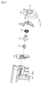
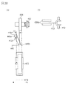
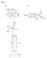
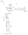
- FIG. 1 is a perspective view of a process cartridge according to the first embodiment.
- FIG. 2 is a sectional view of the image forming apparatus according to the first embodiment.
- FIG. 3 is a perspective view of the image forming apparatus according to the first embodiment.
- FIG. 4 is a cross-sectional view of the process cartridge according to the first embodiment.
- FIG. 5 is a perspective view of the process cartridge according to the first embodiment.
- FIG. 6 is a perspective view of the process cartridge according to the first embodiment.
- FIG. 7 is a side view of the process cartridge according to the first embodiment.
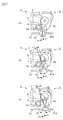
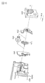
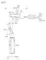
- FIG. 8 is a perspective view of the drive connecting portion according to the first embodiment.
- FIG. 9 is a perspective view of the drive connecting portion according to the first embodiment.
- FIG. 10 is a perspective view of the drive connecting portion according to the first embodiment.
- FIG. 11 is a perspective view of the drive connecting portion according to the first embodiment.
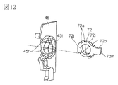
- FIG. 12 is a perspective view of a release member and peripheral parts according to the first embodiment.
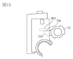
- FIG. 13 is a perspective view of a release member and peripheral parts according to the first embodiment.
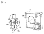
- FIG. 14 is a perspective view of the drive connecting portion according to the first embodiment.
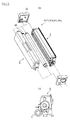
- FIG. 15 is a perspective view of the process cartridge according to the first embodiment.
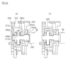
- FIG. 16 is a cross-sectional view of the drive connecting portion according to the first embodiment.
- FIG. 17 is a schematic view and a perspective view of the drive connecting portion according to the first embodiment.
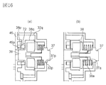
- FIG. 18 is a schematic view and a perspective view of the drive connecting portion according to the first embodiment.
- FIG. 19 is a schematic view and a perspective view of the drive connecting portion according to the first embodiment.
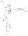
- FIG. 20 is a perspective view of a process cartridge according to the second embodiment.
- FIG. 21 is a perspective view of a release member and peripheral parts according to the second embodiment.
- FIG. 22 is a perspective view of the drive connecting portion according to the second embodiment.
- FIG. 23 is a cross-sectional view of the drive connecting portion according to the second embodiment.
- FIG. 24 is a schematic view and a perspective view of the drive connecting portion according to the second embodiment.
- FIG. 25 is a schematic view and a perspective view of the drive connecting portion according to the second embodiment.
- FIG. 26 is a schematic view and a perspective view of the drive connecting portion according to the second embodiment.
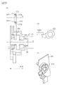
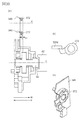
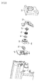
- FIG. 27 is a perspective view of a process cartridge according to the third embodiment.
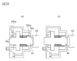
- FIG. 28 is a cross-sectional view of the drive connecting portion according to the third embodiment.
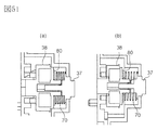
- FIG. 29 is a schematic view and a perspective view of a drive connecting portion according to the third embodiment.
- FIG. 30 is a schematic view and a perspective view of a drive connecting portion according to the third embodiment.
- FIG. 31 is a schematic view and a perspective view of the drive connecting portion according to the third embodiment.
- FIG. 32 is a perspective view of a process cartridge according to the fourth embodiment.
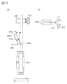
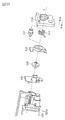
- FIG. 33 is a perspective view of a release member and peripheral parts according to the fourth embodiment.
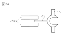
- FIG. 34 is a perspective view of a release member and peripheral parts according to the fourth embodiment.
- FIG. 35 is a cross-sectional view of the drive connecting portion according to the fourth embodiment.
- FIG. 36 is a schematic view and a perspective view of a drive connecting portion according to the fourth embodiment.
- FIG. 37 is a schematic view and a perspective view of the drive connecting portion according to the fourth embodiment.
- FIG. 38 is a schematic view and a perspective view of the drive connecting portion according to the fourth embodiment.
- FIG. 39 is a perspective view of a process cartridge according to the fifth embodiment.
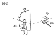
- FIG. 40 is a perspective view of a release member and peripheral parts according to the fifth embodiment.
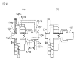
- FIG. 41 is a cross-sectional view of the drive connecting portion according to the fifth embodiment.
- FIG. 42 is a schematic view and a perspective view of the drive connecting portion according to the fifth embodiment.
- FIG. 43 is a schematic view and a perspective view of the drive connecting portion according to the fifth embodiment.
- FIG. 44 is a schematic view and a perspective view of the drive connecting portion according to the fifth embodiment.
- FIG. 45 is a perspective view of a process cartridge according to the sixth embodiment.
- FIG. 46 is a cross-sectional view of the drive connecting portion according to the sixth embodiment.
- FIG. 48 is a schematic view and a perspective view of a drive connecting portion according to the sixth embodiment.
- FIG. 49 is a schematic view and a perspective view of the drive connecting portion according to the sixth embodiment.
- FIG. 50 is a perspective view of a process cartridge according to the seventh embodiment.
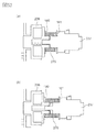
- FIG. 51 is a cross-sectional view of the drive connecting portion according to the seventh embodiment.
- FIG. 52 is a sectional view of the drive connecting portion according to the seventh embodiment.
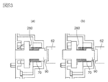
- FIG. 53 is a sectional view of the drive connecting portion according to the seventh embodiment.
- a full-color image forming apparatus in which four process cartridges can be attached and detached is illustrated as an image forming apparatus.
- the number of process cartridges attached to the image forming apparatus is not limited to this. It is appropriately set as necessary.
- the number of process cartridges attached to the image forming apparatus is one.
- a printer is illustrated as an example of an image forming apparatus. [Schematic configuration of image forming apparatus]
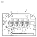
- FIG. 2 is a schematic sectional view of the image forming apparatus of this embodiment.
- 3A and 3B are perspective views of the image forming apparatus of the present embodiment.
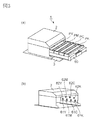
- FIG. 4 is a sectional view of the process cartridge P of this embodiment.
- FIG. 5 is a perspective view of the process cartridge P of the present embodiment as viewed from the driving side, and
- FIG. 6 is a perspective view of the process cartridge P of the present embodiment as viewed from the non-driving side.
- the image forming apparatus 1 is a four-color full-color laser printer using an electrophotographic image forming process, and forms a color image on a recording medium S.
- the image forming apparatus 1 is a process cartridge type, and the process cartridge is detachably mounted on the electrophotographic image forming apparatus main body 2 to form a color image on the recording medium S.
- FIG. 2 is a cross-sectional view of the image forming apparatus 1 as viewed from the non-driving side.
- the front side of the sheet is the non-driving side of the image forming apparatus 1
- the right side of the sheet is the front of the image forming apparatus 1
- the back side of the sheet is the driving of the image forming apparatus 1.
- the four process cartridges P are arranged in the horizontal direction.
- the four cartridges are a first process cartridge PY (yellow), a second process cartridge PM (magenta), a third process cartridge PC (cyan), and a fourth process cartridge PK (black), respectively.
- Each of the first to fourth process cartridges P has the same electrophotographic image forming process mechanism, and the developer (toner) colors held therein are different from each other. .
- the first to fourth process cartridges P receive a rotational driving force from the drive output unit of the image forming apparatus main body 2. Details will be described later.
- a bias voltage (charging bias, developing bias, etc.) is supplied from the image forming apparatus main body 2 to each of the first to fourth process cartridges P (PY, PM, PC, PK) (not shown).
- each of the first to fourth process cartridges P (PY / PM / PC / PK) of this embodiment includes a photosensitive drum unit (photosensitive unit, image carrier unit) 8.
- the photoconductor unit 8 includes a photoconductor drum 4 and a charging unit and a cleaning unit as process units that act on the drum 4.
- each of the first to fourth process cartridges P has a developing unit 9 provided with developing means for developing the electrostatic latent image on the drum 4.
- the first process cartridge PY contains a yellow (Y) developer in the developing frame 29 and forms a yellow developer image on the surface of the drum 4.
- the second process cartridge PM contains a magenta (M) developer in the developing frame 29 and forms a magenta developer image on the surface of the drum 4.
- M magenta
- the third process cartridge PC contains cyan (C) developer in the developing frame 29 and forms a cyan developer image on the surface of the drum 4.
- the fourth process cartridge PK contains a black (K) developer in the developing frame 29 and forms a black developer image on the surface of the drum 4.
- a laser scanner unit LB as exposure means is provided above the first to fourth process cartridges P (PY, PM, PC, PK).
- the laser scanner unit LB outputs a laser beam Z corresponding to the image information. Then, the laser beam Z passes through the exposure window 10 of the cartridge P and scans and exposes the surface of the drum 4.
- An intermediate transfer belt unit 11 as a transfer member is provided below the first to fourth cartridges P (PY, PM, PC, PK).
- the intermediate transfer belt unit 11 includes a driving roller 13 and tension rollers 14 and 15, and a flexible transfer belt 12 is stretched over the intermediate transfer belt unit 11.
- the lower surface of the drum 4 of each of the first to fourth cartridges P (PY, PM, PC, PK) is in contact with the upper surface of the transfer belt 12.
- the contact portion is a primary transfer portion.
- a primary transfer roller 16 is provided inside the transfer belt 12 so as to face the drum 4.
- the secondary transfer roller 17 is disposed via the transfer belt 12 at a position facing the tension roller 14. A contact portion between the transfer belt 12 and the secondary transfer roller 17 is a secondary transfer portion.
- a feeding unit 18 is provided below the intermediate transfer belt unit 11.
- the feeding unit 18 includes a paper feeding tray 19 and a paper feeding roller 20 in which the recording media S are stacked and stored.
- the apparatus body 2 is provided with a fixing unit 21 and a discharge unit 22 at the upper left in the apparatus main body 2.
- the upper surface of the apparatus body 2 is a discharge tray 23.
- the recording medium S to which the developer image has been transferred is fixed by fixing means provided in the fixing unit 21 and then discharged to the discharge tray 23.
- the cartridge P is configured to be detachable from the apparatus main body 2 via a cartridge tray 60 that can be pulled out.
- FIG. 3A shows a state in which the cartridge tray 60 and the cartridge P are pulled out from the apparatus main body 2.
- FIG. 3B shows a state in which the cartridge tray 6 is removed from the apparatus main body 2.
- the operation for forming a full color image is as follows.
- the drum 4 of each of the first to fourth cartridges P (PY, PM, PC, PK) is rotated at a predetermined speed (in the direction of arrow D in FIG. 4, counterclockwise in FIG. 2).
- the transfer belt 12 is also rotationally driven at a speed corresponding to the speed of the drum 4 in the forward direction (direction of arrow C in FIG. 2) with respect to the rotation of the drum.
- the laser scanner unit LB is also driven. In synchronization with the driving of the scanner unit LB, the surface of the drum 4 is uniformly charged to a predetermined polarity and potential by the charging roller 5. The laser scanner unit LB scans and exposes the surface of each drum 4 with a laser beam Z according to the image signal of each color.
- an electrostatic latent image corresponding to the image signal of the corresponding color is formed on the surface of each drum 4.
- This electrostatic latent image is developed by a developing roller 6 that is rotationally driven (in the direction of arrow E in FIG. 4, clockwise in FIG. 2) at a predetermined speed.
- a yellow developer image corresponding to the yellow component of the full-color image is formed on the drum 4 of the first cartridge PY. Then, the developer image is primarily transferred onto the transfer belt 12.
- magenta developer image corresponding to the magenta component of the full-color image is formed on the drum 4 of the second cartridge PM.
- the developer image is primary-transferred superimposed on the yellow developer image already transferred onto the transfer belt 12.
- a cyan developer image corresponding to the cyan component of the full-color image is formed on the drum 4 of the third cartridge PC. Then, the developer image is primary-transferred superimposed on the yellow and magenta developer images already transferred onto the transfer belt 12.
- a black developer image corresponding to the black component of the full-color image is formed on the drum 4 of the fourth cartridge PK. Then, the developer image is primary-transferred superimposed on the yellow, magenta, and cyan developer images already transferred onto the transfer belt 12.
- the recording media S are separated and fed one by one at a predetermined control timing.
- the recording medium S is introduced into a secondary transfer portion which is a contact portion between the secondary transfer roller 17 and the transfer belt 12 at a predetermined control timing.
- the first to fourth cartridges P (PY, PM, PC, PK) have the same electrophotographic image forming process mechanism, and the color of the developer and the filling amount of the developer are accommodated. Are different from each other.
- the cartridge P includes a drum 4 as a photosensitive member and process means acting on the drum 4.
- the process means includes a charging roller 5, a developing roller 6, a cleaning blade 7, and the like.
- the charging roller is charging means (charging member, charging device) for charging the drum 4.
- the developing roller 6 is a developing means (developing member, developer carrying member) for developing the latent image formed on the drum 4.
- the cleaning blade 7 is a cleaning unit for removing the residual developer remaining on the surface of the drum 4.
- the cartridge P is divided into a drum unit 8 and a developing unit 9. [Drum unit configuration]
- the drum unit 8 includes a drum 4 as a photosensitive member, a charging roller 5, a cleaning blade 7, a cleaning container 26 as a photosensitive member frame, and a waste developer storage unit 27. .
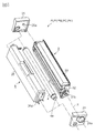
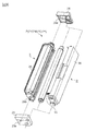
- the drum unit 8 includes a cartridge cover member (the driving side cartridge cover member 24 and the non-driving side cartridge cover member 25 in FIGS. 5 and 6).
- the broad-sense photoconductor frame includes a waste developer container 27, a driving-side cartridge cover member 24, and a non-driving-side cartridge cover member 25 in addition to the cleaning container 26, which is a narrow-sense photoconductor frame. The same applies to the following examples).
- the photoconductor frame is fixed to the apparatus main body 2.
- the drum 4 is rotatably supported by cartridge cover members 24 and 25 provided at both longitudinal ends of the cartridge P.
- the axial direction of the drum 4 is defined as the longitudinal direction.
- the cartridge cover members 24 and 25 are fixed to the cleaning container 26 at both ends in the longitudinal direction of the cleaning container 26.
- FIG. 3B is a perspective view of the apparatus main body 2, and the cartridge tray 60 and the cartridge P are not shown.
- Each coupling member 4a of the cartridge P (PY, PM, PC, PK) is a drum drive output member 61 (61Y, 61M, 61C, or the like) as a main body side drive transmission member of the apparatus main body 2 shown in FIG. 61K).
- the driving force of the drive motor (not shown) of the apparatus main body is transmitted to the drum 4 of each cartridge.
- the charging roller 5 is supported by the cleaning container 26 so as to be in contact with the drum 4 and be driven to rotate.
- the cleaning blade 7 is supported by the cleaning container 26 so as to contact the peripheral surface of the drum 4 with a predetermined pressure.
- the transfer residual developer removed from the peripheral surface of the drum 4 by the cleaning means 7 is stored in a waste developer storage portion 27 in the cleaning container 26.
- the drive side cartridge cover member 24 and the non-drive side cartridge cover member 25 are provided with support portions 24a and 25a for rotatably supporting the developing unit 9 (see FIG. 6).
- the developing unit 9 includes a developing roller 6, a developing blade 31, a developing frame 29, a bearing member 45, a developing cover member 32, and the like.
- the developing frame in a broad sense includes the bearing member 45 and the developing cover member 32 in addition to the developing frame 29 (the same applies to the following embodiments).
- the developing frame 29 can move with respect to the apparatus main body 2.
- the broadly defined cartridge frame includes the above-described broadly defined photoreceptor frame and broadly defined developing frame (the same applies to the following embodiments).
- the developing frame 29 has a developer accommodating portion 49 that accommodates the developer supplied to the developing roller 6 and a developing blade 31 that regulates the layer thickness of the developer on the peripheral surface of the developing roller 6.
- an upstream drive transmission member (upstream transmission member) 37 provided at the drive side end of the developing unit 9 is a main body side drive transmission member (main body side transmission member) of the apparatus main body 2 shown in FIG. Is engaged with the development drive output member 62 (62Y, 62M, 62C, 62K).
- the upstream drive transmission member 37 is configured to transmit a driving force from a drive motor (not shown) provided in the apparatus main body 2.
- the developing cover member 32 is fixed to the outside of the bearing member 45 in the longitudinal direction of the cartridge P.
- the developing cover member 32 is configured to cover the developing roller gear 69 and the like.
- FIG 5 and 6 show how the developing unit 9 and the drum unit 8 are assembled.
- the outer diameter portion 32a of the cylindrical portion 32b of the developing cover member 32 is rotatably fitted to the support portion 24a of the driving side cartridge cover member 24.
- a projecting portion 29b provided so as to project from the developing frame 29 is fitted into the support hole portion 25a of the non-driving side cartridge cover member 25 so as to be rotatable.
- the developing unit 9 is supported so as to be rotatable with respect to the drum unit 8.
- rotation center (rotation axis) of the developing unit 9 with respect to the drum unit is referred to as a rotation center (rotation axis) X.
- the rotation center X is an axis connecting the center of the support hole 24a and the center of the support hole 25a.
- the developing unit 9 is biased by a pressure spring 95 that is an elastic member (biasing member), and rotates about a rotation center X.
- the developing roller 6 is configured to come close to and come into contact with the drum 4. That is, the developing unit 9 is pressed in the direction of arrow G in FIG. 4 by the urging force of the pressure spring 95, and a moment in the direction of arrow H acts around the rotation center X.
- the developing roller 6 comes close to the drum 4 and can contact the drum 4 with a predetermined pressure.
- the position of the developing unit 9 with respect to the drum unit 8 at this time is defined as a close position (contact position, developing position).
- the position of the developing roller 6 with respect to the drum 4 at this time may be referred to as a proximity position (contact position, development position). Since the developing roller 6 is in the proximity position, toner (developer) can be supplied to the drum 4 to develop the latent image (electrostatic latent image) formed on the drum 4.
- the developing roller 6 can be separated from the drum 4. That is, the developing roller 6 is configured to be close to and away from the drum 4.
- FIG. 7 is a side view of the cartridge P as viewed from the drive side. In this figure, some parts are not shown for the sake of explanation.
- the drum unit 8 is positioned on the apparatus main body 2.
- a force receiving portion 45a is provided on the bearing member 45.
- the force receiving portion 45a is not limited to the bearing member 45, and may be provided at any location (for example, the developing device frame) of the cartridge P.
- the force receiving portion 45a as an urging force receiving portion (separating force receiving portion) is configured to be engageable with a main body separating member 80 as a main body side urging member (separating force applying member) provided in the apparatus main body 2. ing.
- the main body separating member 80 as the main body side urging member is configured to receive a driving force from a motor (not shown) and to move along the rails 81 in the directions of arrows F1 and F2.
- FIG. 7A shows a state where the drum 4 and the developing roller 6 are in contact with each other. At this time, the force receiving portion 45a and the main body separation member 80 are separated with a gap d.
- FIG. 7B shows a state in which the main body separation member 80 has moved by a distance ⁇ 1 in the direction of the arrow F1 with reference to the state of FIG. 7A.
- the force receiving portion 45 a is engaged with the main body separation member 80.
- the force receiving portion 45 a receives a force from the main body separating member 80.
- the developing unit 9 is configured to be rotatable with respect to the drum unit 8. Therefore, in FIG. 7B, the developing unit 9 is rotated about the rotation center X by an angle ⁇ 1 in the direction of the arrow K by the force received by the force receiving portion 45a. At this time, the drum 4 and the developing roller 6 are separated from each other by a distance ⁇ 1.
- FIG. 7C shows a state in which the main body separation member 80 has moved by ⁇ 2 (> ⁇ 1) in the direction of the arrow F1 with reference to the state of FIG. 7A.
- the developing unit 9 is rotated about the rotation center X by an angle ⁇ 2 in the arrow K direction. At this time, the drum 4 and the developing roller 6 are separated from each other by a distance ⁇ 2.
- the distance between the force receiving portion 45a and the rotation center of the drum 4 is in the range of 13 mm to 33 mm.
- the distance between the force receiving portion 45a and the rotation center X is in the range of 27 mm to 32 mm.
- the drive connecting portion is a mechanism that receives drive from the development drive output member 62 of the apparatus main body 2 shown in FIG.
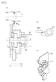
- FIG. 8 is a perspective view of the process cartridge P as viewed from the drive side, and shows a state where the drive side cartridge cover member 24 and the developing cover member 32 are removed.
- the drive side cartridge cover member 24 is provided with openings 24d and 24e.
- the coupling member 4a provided at the end of the photosensitive drum 4 is exposed from the opening 24d, and the upstream drive transmission member 37 is exposed from 24e.
- the coupling member 4a is engaged with the drum drive output member 61 (61Y, 61M, 61C, 61K) of the apparatus main body 2 shown in FIG. 3B, and the drive motor (not shown) of the apparatus main body is engaged. It is configured to receive driving force.
- the upstream drive transmission member 37 engages with the development drive output member 62 (62Y, 62M, 62C, 62K) as the main body side drive transmission member of the apparatus main body 2 shown in FIG.
- the driving force from a drive motor (not shown) provided in the vehicle is transmitted.
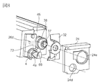
- an upstream drive transmission member (upstream transmission member) 37 as a first drive transmission member and a downstream drive transmission member (downstream transmission member) 38 as a second drive transmission member are provided at the end of the developing unit 9. Is rotatably provided.
- the upstream drive transmission member 37 and the downstream drive transmission member 38 are engaged with each other by the claw portions, the drive is transmitted from the upstream drive transmission member 37 to the downstream drive transmission member 38. It can be configured.
- the gear portion 38 g provided on the downstream drive transmission member 38 as the second drive transmission member is also engaged with the developing roller gear 69. As a result, the drive transmitted to the downstream drive transmission member 38 is transmitted to the developing roller 6 via the developing roller gear 69.
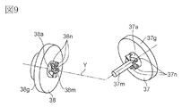
- the configuration of the upstream drive transmission member 37 and the downstream drive transmission member 38 will be described with reference to FIG.
- the upstream drive transmission member 37 has a claw portion 37a as an engagement portion (coupling portion), and the downstream drive transmission member 38 has a claw portion 38a as an engagement portion (coupling portion).
- the claw portion 37a and the claw portion 38a are configured to be engageable with each other. That is, the upstream drive transmission member 37 is configured to be connectable to the downstream drive transmission member 38.
- the claw portion 37a and the claw portion 38a each have six claws.
- the number of claw portions 37a and claw portions 38a is six, but the number is not limited to this. For example, FIG.
- the number of the claw portions 1037a and the claw portions 1038a of the upstream drive transmission member 1037 is nine.
- the larger the number of nails the smaller the load acting on one nail, and the deformation and wear of the nail can be reduced.
- the outer diameter of the coupling is constant, when the number of claws is increased, the shape of the claws may be reduced, and there is a concern that the rigidity of the claws is reduced. It is desirable that the number of nails is appropriately determined in view of a load acting on one nail and necessary rigidity.
- the claw 37a is employed as the engaging portion (projection) provided on the upstream drive transmission member 37
- the claw 38a is employed as the engagement portion (projection) provided on the downstream drive transmission member 38.
- the shape of the joint is not limited to the nail shape. It is only necessary that the drive can be transmitted when the engaging portions are engaged (interfered) with each other.
- a hole 38 m is provided in the center of the downstream drive transmission member 38.
- the hole 38m engages with a small-diameter cylindrical portion (circular column portion, shaft portion) 37m of the upstream drive transmission member 37.
- the cylindrical portion 37m passes through the hole 38m.
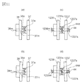
- FIG. 11 shows different positioning configurations of the upstream drive transmission member 37 and the downstream drive transmission member 38.
- FIG. 11A the hole 38m of the downstream drive transmission member 38 and the small diameter cylindrical portion 37m of the upstream drive transmission member 37 as shown in FIG. This is the configuration of this embodiment.
- FIG. 11C shows a configuration in which the upstream drive transmission member 1237 and the downstream drive transmission member 1238 are positioned via a shaft (column portion, shaft portion) 44 that is a separate member from each drive transmission member. .
- the hole portion 1238m of the upstream drive transmission member 1237 and the outer peripheral portion 44d of the shaft 44, and the hole portion 1037s of the upstream drive transmission member 1037 and the outer peripheral portion 44d of the shaft 44 are rotatable and have their respective axes. It is supported so that it can slide along. Thereby, the positioning of the downstream drive transmission member 1038 with respect to the upstream drive transmission member 1037 is performed.
- FIG. 11A Either the configuration shown in FIG. 11A or the configuration shown in FIG. 11C can be adopted.
- the configuration shown in FIG. 11A reduces the number of parts for positioning the upstream drive transmission member 37 and the downstream drive transmission member 38 as compared with the configuration of FIG. 11C.
- FIG. 11B shows the state where the upstream drive transmission member 37 and the downstream drive transmission member 38 shown in FIG. 11A cannot transition from the drive release state to the drive transmission state. Yes.
- Fitting occurs between the hole 38m of the downstream drive transmission member 38 and the small-diameter cylindrical portion 37m of the upstream drive transmission member 37.
- the fitting backlash is intentionally enlarged for explanation. If the aforementioned engagement play is large, when the upstream drive transmission member 37 and the downstream drive transmission member 38 are engaged, the two parts are relatively misaligned by the engagement play. There is a possibility that they cannot be matched (FIG. 11B). Therefore, it is necessary to keep such fitting backlash within an allowable range.
- the downstream drive transmission member 38 and the upstream drive transmission member 37 are directly engaged with each other, so that the engagement play generated between the downstream drive transmission member 38 and the upstream drive transmission member 37 is reduced. Has the advantage of being easy to do.
- FIG. 11D shows that the upstream drive transmission member 1037 as the first drive transmission member and the downstream drive transmission member 1038 as the second drive transmission member shown in FIG. This shows a state where the transition to the transmission state could not be made.
- the upstream drive transmission member 1037 and the downstream drive transmission member 1038 are relatively misaligned due to the number of parts and the influence of the dimensional error.
- the relative misalignment amount at this time may be larger in the configuration shown in FIG. 11D than in the configuration shown in FIG.
- the claw portions 1037a and the claw of the respective couplings with the upstream drive transmission member 1037 and the downstream drive transmission member 1038 being relatively misaligned.
- the coupling claw portion 1037a and the claw portion 1038a are likely to be in contact with each other only at the tip portions, which may affect drive transmission.
- the upstream drive transmission member 37 and the downstream drive transmission member 38 be directly positioned with respect to each other (configuration shown in FIG. 9 and FIG. 11A). Further, in the configuration shown in FIG. 11A, effects such as reduction in the number of parts and reduction in the number of assembly steps can be obtained.
- the following are provided from the bearing member 45 toward the drive side cartridge cover member 24. That is, as disclosed in FIG. 1, the release cam 72, the downstream drive transmission member 38 as the second coupling member, the spring 70 as the elastic member as the biasing member, and the upstream drive transmission as the first coupling member The member 37 and the developing cover member 32. These members are provided on the same straight line as the upstream drive transmission member 37. That is, the upstream drive transmission member, the spring 70, and the downstream drive transmission member 38 are arranged coaxially along the same rotation axis and can rotate around the same axis.
- the drive connecting portion includes the bearing member 45, the release cam 72, the downstream drive transmission member 38, the spring 70, the upstream drive transmission member 37, the developing cover member 32, and the drive cartridge cover member 24.
- the release cam (cam member) 72 is a part of the release mechanism, is a coupling release member, and is also an action member.
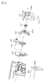
- FIG. 12 shows the relationship between the release cam 72 and the bearing member 45.
- the release cam 72 has a ring portion 72j having a substantially ring shape.
- the ring portion 72j has an outer peripheral surface 72i as a second guided portion
- the bearing member 45 has an inner peripheral surface 45i as a part of the second guide portion.
- the inner peripheral surface 45i is configured to engage with the outer peripheral surface 72i.
- the outer peripheral surface 72 i of the release cam 72 and the inner peripheral surface 45 i of the bearing member 45 are both arranged on the same straight line (coaxial) with respect to the rotation center X. That is, the release cam 72 can slide (translate) along the rotation axis X (axial direction) with respect to the bearing member 45 and the developing unit 9. Further, the release cam 72 is supported so as to be rotatable with respect to the developing unit 9 also in the rotation direction about the axis X.
- the ring portion 72j of the release cam 72 as a coupling release member has a contact portion (slope, cam portion) 72a as a force receiving portion.
- the bearing member 45 has a contact portion (slope, cam portion) 45r as a force applying portion for applying a force to the contact portion 72a.
- the abutting portion 72 a and the abutting portion 45 r are inclined portions that are inclined with respect to the direction in which the developing unit 4 moves relative to the drum unit 8.
- the contact portion 72a of the release cam 72 and the contact portion 45r of the bearing member 45 are configured to be contactable.
- the release cam 72 and the bearing member 45 constitute a cam mechanism, and this cam mechanism is activated by the movement of the developing unit 9.
- FIG. 13 shows the configuration of the release cam 72 and the restricting portion 26d provided in the cleaning container 26.
- the restricting portion 26d provided in the cleaning container 26 is installed inside the cleaning container, but may be installed anywhere in the cleaning container 26 depending on the shape of the cleaning container 26.
- the release cam 72 has a protruding portion 72m protruding from the ring portion 72j. This protrusion has a force receiving portion 72b as a second guided portion.
- the force receiving portion 72 b receives a force from the cleaning container 26 by engaging with a restricting portion 26 d as a part of the second guide portion of the cleaning container 26.
- the force receiving portion 72 b is configured to protrude from the developing cover member 32 and engage with the restricting portion 26 d of the cleaning container 26.
- the release cam 72 Since the restricting portion 26d and the force receiving portion 72b are engaged, the release cam 72 is slidable only in the axial direction (arrow M and N directions) with respect to the drive side cartridge cover member 24. It has a configuration. That is, the rotation of the release cam 72 is restricted (restricted) with respect to the drum unit (cleaning container 26).
- the outer diameter portion 32a of the cylindrical portion 32b of the developing cover member 32 is configured to slide with the sliding portion 24a (cylindrical inner surface) of the driving side cartridge cover member 24. That is, the outer diameter portion 32a is rotatably coupled to the sliding portion 24a.
- the release cam 72 is engaged with both the inner peripheral surface 45i of the bearing member 45 and the regulating portion 26d of the cleaning container 26. That is, the release cam 72 is slidable (rotatable) with respect to the developing unit 9 in the axial direction (arrow M and N directions) and the rotational direction about the axis X. On the other hand, with respect to the drum unit 8 (drive side cartridge cover member 24), the release cam 72 is configured to be slidable in the axial direction (arrow M and N directions).
- FIG. 15A is a perspective view of the cartridge P schematically showing the force acting on the developing unit 9
- FIG. 15B is a side view of the cartridge P viewed along the axis X direction. A part of the figure is shown.
- the developing unit 9 is subjected to a reaction force Q1 from the pressure spring 95, a reaction force Q2 received from the drum 4 via the developing roller 6, and a self-weight Q3.
- the release cam 72 is engaged with the cleaning container 26 and receives a reaction force Q4 (details will be described later).
- the resultant force Q0 of the reaction forces Q1, Q2, Q4 and the own weight Q3 is the support holes 24a of the drive side and non-drive side cartridge cover members 24, 25 that rotatably support the developing unit 9. 25a and the bearing member 45.
- the sliding portion 24a of the driving side cartridge cover member 24 that contacts the developing cover member 32 is required in the direction of the resultant force Q0. . That is, the sliding portion 24a of the drive side cartridge cover member 24 has a resultant force receiving portion 24a1 that receives the resultant force Q0 (see FIG. 14).
- the cylindrical portion 32b of the developing cover member 32 and the sliding portion 24a of the driving side cartridge cover member 24 are not necessarily required except in the direction of the resultant force Q0.
- An opening 32c is provided on the opposite side of Q0.
- a release cam 72 that engages with the restricting portion 26d of the cleaning container 26 is disposed in the opening 32c.
- 16A and 16B are cross-sectional views of the drive connecting portion.
- the cylindrical portion 38p (cylindrical inner surface) of the downstream drive transmission member 38 and the first bearing portion 45p (cylindrical outer surface) of the bearing 45 are engaged with each other. Further, the cylindrical portion 38q (cylindrical outer surface) of the downstream drive transmission member 38 and the inner diameter portion 32q of the developing cover member 32 are engaged with each other. That is, both ends of the downstream drive transmission member 38 are rotatably supported by the bearing member 45 and the developing cover member 32.
- the cylindrical portion 37p (cylindrical outer surface) of the upstream drive transmission member 37 and the hole portion 32p of the developing cover member 32 are engaged with each other. Accordingly, the upstream drive transmission member 37 is supported so as to be slidable (rotatable) with respect to the developing cover member 32.
- the first bearing portion 45p (cylindrical outer surface) of the bearing member 45, the inner diameter portion 32q of the developing cover member 32, and the hole portion 32p are arranged on the same straight line as the rotation center X of the developing unit 9. That is, the upstream drive transmission member 37 is supported so as to be rotatable about the rotation center X of the developing unit 9. Further, as described above, the cylindrical portion 37m of the upstream drive transmission member 37 and the hole 38m of the downstream drive transmission member 38 are engaged (see FIG. 9). As a result, the downstream drive transmission member 38 is also supported so as to be rotatable about the rotation center X of the developing unit 9.
- the sectional view of the drive connecting portion shown in FIG. 16A shows a state in which the claw 38a of the downstream drive transmission member 38 and the claw 37a of the upstream drive transmission member 37 are engaged with each other.
- 16B shows a state where the claw 38a of the downstream drive transmission member 38 and the claw 37a of the upstream drive transmission member 37 are separated from each other.
- FIGS. 17 (a) and 17 (b) show a perspective view of the structure of the drive connecting portion.
- FIGS. 17A, 17B, and 17C some parts are not shown for the sake of explanation.
- FIG. 17A a pair of the upstream drive transmission member 37 and the downstream drive transmission member 38 and a pair of the release cam 72 and the bearing member 45 are separately shown.
- FIG. 17A a pair of the upstream drive transmission member 37 and the downstream drive transmission member 38 and a pair of the release cam 72 and the bearing member 45 are separately shown.
- FIG. 17A a pair of the upstream drive transmission member 37 and the downstream drive transmission member 38 and a pair of the release cam 72 and the bearing member 45 are separately shown.
- FIG. 17A a pair of the upstream drive transmission member 37 and the downstream drive transmission member 38 and a pair of the release cam 72 and the bearing member 45 are separately shown.
- the bearing member 45 displays only a part including the contact part 45r
- the cleaning container 26 displays only a part including the restricting part 26d.
- the claw 37a of the upstream drive transmission member 37 and the claw 38a of the downstream drive transmission member 38 are engaged with each other with an engagement amount q so that drive transmission is possible.
- the downstream drive transmission member 38 is engaged with the developing roller gear 69 (see FIG. 59). Therefore, the driving force input from the apparatus main body 2 to the upstream drive transmission member 37 is transmitted to the developing roller gear 69 via the downstream drive transmission member 38. Thereby, the developing roller 6 is driven.
- the above state of each component is referred to as a contact position, and is also referred to as a development contact / drive transmission state.
- the position of the downstream drive transmission member 38 at this time is particularly referred to as a transmission position (connection position, engagement position).
- the position of the release cam 72 at this time is particularly called a maintenance position (biasing position).
- the release cam 72 biases the downstream drive transmission member 38 toward the upstream drive transmission member 37 against the elastic force of the spring 70 when in the maintenance position. As a result, the release cam 72 holds the downstream drive transmission member 38 in the transmission position.
- release cam 72 functions as a maintenance member (biasing member) for urging the downstream drive transmission member 38 to maintain it in the transmission position.
- the developing unit 9 is centered on the rotation center X as described above. Is rotated in the direction of arrow K by an angle ⁇ 1. As a result, the developing roller 6 is separated from the drum 4 by a distance ⁇ 1.
- the bearing member 45 incorporated in the developing unit 9 rotates in the arrow K direction by an angle ⁇ 1 in conjunction with the rotation of the developing unit 9.
- the release cam 72 is incorporated in the developing unit 9, but the force receiving portion 72b is engaged with the engaging portion 26d of the cleaning container 26 as shown in FIG. Therefore, even if the developing unit 9 rotates, the release cam 72 does not rotate.
- the release cam 72 and the bearing member 45 are a cam mechanism that moves the downstream drive transmission member 38 in conjunction with the movement (rotation) of the developing unit 9.
- the release cam 72 moves along the X axis.
- the downstream drive transmission member 38 moves along with the release cam 72 along the X axis.
- the contact portion 45r of the bearing member 45 moves relative to the contact portion 72a of the release cam 72.
- the release cam 72 is pressed by the spring 70 via the downstream drive transmission member 38. Therefore, the contact portion 72a slides with respect to the contact portion 45r using the force of the spring 70.
- the release cam 72 itself also slides in the N direction of the X axis with respect to the bearing member 45 using the force of the spring 70. That is, the release cam 72 is retracted in a direction away from the downstream drive transmission member 38.
- the driving force input from the apparatus main body 2 to the upstream drive transmission member 37 is transmitted to the developing roller 6 via the downstream drive transmission member 38 and the developing roller gear 69.
- the above-described state of each component is referred to as a development separation / drive transmission state.
- the force receiving portion 72b does not necessarily have to be in contact with the engaging portion 26d of the cleaning container 26. That is, in the state 1, the force receiving portion 72b may be disposed with a gap with respect to the engaging portion 26d of the cleaning container 26. In this case, during the operation from the state 1 to the state 2, there is no gap between the force receiving portion 72b and the engaging portion 26d of the cleaning container 26, and the force receiving portion 72b becomes the engaging portion 26d of the cleaning container 26. It will abut. [State 3]
- FIG. 7C the structure of the drive connecting portion when the main body separating member 80 is moved by ⁇ 2 in the direction of the arrow F1 in the drawing from the developing separation / drive transmission state is shown in FIGS. It is shown in 19 (b).
- the bearing member 45 rotates in conjunction with the rotation of the developing unit 9 at the angle ⁇ 2 (> ⁇ 1).
- the release cam 72 is restricted so that its force receiving portion 72b engages with the engaging portion 26d of the cleaning container 26 so as to be movable only in the axial direction (arrow M and N directions) (FIG. 13). reference).
- the contact portion 72 a of the release cam 72 slides with respect to the contact portion 45 r of the bearing member 45.
- the release cam 72 and the downstream drive transmission member 38 slide in the direction of arrow N by the movement amount p2 due to the pressing force of the spring 70. (See FIG. 19 and FIG. 16B).
- the position of the downstream drive transmission member 38 at this time is particularly called a blocking position (release position). Further, the position of the release cam 72 at this time is particularly called an allowable position.
- the release cam 72 allows the downstream drive transmission member 38 to move to the blocking position by the force of the spring 70 by moving from the maintenance position to the allowable position.
- the claw 37a intermittently contacts the claw 38a when the upstream drive transmission member 37 rotates. It is also possible. Even in this state, it can be considered that the connection between the upstream and downstream drive transmission members is released. However, in order to suppress wear of the claw 37a and the claw 38a and to suppress the generation of sound in a state where the drive transmission is released, the claw 38a and the upstream side of the downstream drive transmission member 38 are released when the drive connection is released. It is more desirable that the claw 37a of the drive transmission member 37a does not contact.
- the process cartridge has a drive transmission member (downstream drive transmission member 38) that can rotate and move along the axial direction.
- the transmission position where the downstream drive transmission member 38 is connected to the upstream transmission member (upstream drive transmission member 37) (FIG. 16A), and the blocking position where the drive connection is canceled (FIG. 16B). It is possible to move between.
- the downstream side drive transmission member 38 is moved to the transmission position. Move to the shut-off position.
- the developing roller 6 can be separated from the drum 4 while rotating, and the drive to the developing roller 6 can be cut off according to the separation distance between the developing roller 6 and the drum 4.
- downstream drive transmission member 38 is moved by using the elastic force of the spring 70 disposed between the downstream drive transmission member 38 and the upstream drive transmission member 37. Since the downstream drive transmission member 38 can stably move from the transmission position to the blocking position using the elastic force, the drive transmission can be reliably cut according to the separation of the developing roller 6.
- the load applied to the developing roller 6 and the toner carried on the developing roller 6 can be reduced by stopping the driving of the developing roller 6 away from the developing roller 6 drum 4. it can. [Drive coupling operation]
- the drive connecting portion is as shown in FIGS. 19A, 19B and 19C. That is, the engagement between the claw 37a of the upstream drive transmission member 37 and the claw 38a of the downstream drive transmission member 38 is released.
- the force receiving portion 72d of the release cam 72 is engaged with the engaging portion 26d of the cleaning container 26 and does not rotate. Therefore, the bearing member 45 moves relative to the release cam 72. As a result, the contact portion 45r of the bearing member 45 urges the contact portion 72a while sliding relative to the contact portion 72a of the release cam 72.
- the release cam 72 slides only in the direction of arrow M by the force received from the contact portion 45r.
- the pressing surface 72c as the urging portion (force applying portion) of the release cam 72 is urged by the urged portion (force receiving portion) of the downstream drive transmission member 38. Part) is pressed (biased).
- the downstream drive transmission member 38 moves in the direction of arrow M against the pressing force of the spring 70, so that the claw 37a of the upstream drive transmission member 37 and the claw 38a of the downstream drive transmission member 38 are engaged with each other. To do.
- the contact portion 45r of the bearing member 45 converts a force for rotating the developing unit 9 relative to the drum unit 8 into a force for urging the release cam 72 and the downstream drive transmission member 38 in the arrow M direction. Work as a cam part. The force generated when the contact portion 45r contacts the contact portion 72a moves the downstream drive transmission member 38 to the transmission position.
- the release cam 72 acts as a moving member (biasing member) that urges the downstream drive transmission member 38 against the force of the spring 70 and moves it to the drive transmission position.
- the driving force from the apparatus main body 2 is transmitted to the developing roller 6, and the developing roller 6 is rotationally driven. At this time, the developing roller 6 and the drum 4 are kept separated from each other.
- the developing roller 9 and the drum 4 can be brought close to and in contact with each other by gradually rotating the developing unit 9 in the direction of arrow H shown in FIG.
- the force receiving portion 72b of the release cam 72 is configured to engage with the restricting portion 26d of the cleaning container 26, but this is not necessarily limited thereto.
- the force receiving portion 72 b may be configured to engage with the drive side cartridge cover member 24.
- the drive side cartridge cover member 24 is also a member constituting the drum unit 8 like the cleaning container 26.
- the drive transmission member that moves (translates) along the axial direction between the transmission position and the cutoff position is the downstream transmission member (downstream drive transmission member 38).
- the upstream drive transmission member (upstream drive transmission member 237) moves between the transmission position (FIG. 23 (a)) and the blocking position (FIG. 23 (b)).
- the upstream drive transmission member 237 switches between a drive connection state and a drive connection release state with respect to the downstream transmission member (downstream drive transmission member 238). Details will be described below. [Configuration of drive connecting part]
- the following are provided from the bearing member 245 toward the drive side cartridge cover member 224. That is, a downstream drive transmission member (downstream transmission member) 238 as a second coupling member, a spring 70 as an elastic member as an urging member, and an upstream drive transmission member (upstream transmission member as a first coupling member) 237, a release cam 272, and a developing cover member 232. These members are provided on the same straight line as the upstream drive transmission member 237.
- the drive connecting portion includes the bearing member 245, the downstream drive transmission member 238, the spring 70, the upstream drive transmission member 237, the release cam 272, the developing cover member 232, and the drive cartridge cover member 224. It is configured.
- the release cam 272 is a part of the release mechanism, a coupling release member, and an action member.
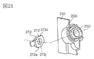
- FIG. 21 shows the relationship between the release cam 272 and the developing cover member 232.
- the release cam 272 has a substantially ring-shaped ring portion 272j.
- the ring portion 272j has an outer peripheral surface 272i as a second guided portion
- the developing cover member 232 has an inner peripheral surface 232i as a part of the second guide portion.
- the inner peripheral surface 232i is configured to engage with the outer peripheral surface 272i.
- the outer peripheral surface 272 i of the release cam 272 and the inner peripheral surface 232 i of the developing cover member 232 are both arranged on the same straight line (coaxial) with respect to the rotation center X. That is, the release cam 272 is slidably movable in the axial direction with respect to the developing cover member 232 and the developing unit 9 and is also supported so as to be rotatable in the rotational direction about the axial line X.
- the ring portion 272j of the release cam 272 as a coupling release member has a contact portion (slope) 272a as a force receiving portion.
- the developing cover member 232 has a contact portion (slope) 232r.
- the contact portion 272a of the release cam 272 and the contact portion 232r of the developing cover member 232 are configured to be in contact with each other.
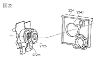
- FIG. 22 shows the configuration of the drive connecting portion and the drive side cartridge cover member 224.
- the release cam 272 has a protruding portion 272m protruding from the ring portion 272j. This protrusion has a force receiving portion 272b as a second guided portion.
- the force receiving portion 272 b receives a force from the driving side cartridge cover member 224 by engaging with a restricting portion 224 d as a part of the second guide portion of the driving side cartridge cover member 224.
- the force receiving portion 272 b protrudes from an opening 232 c provided in a part of the cylindrical portion 232 b of the developing cover member 232 and is configured to engage with the restricting portion 224 d of the driving side cartridge cover member 224.
- the release cam 272 slides (translates) only in the axial direction (arrow M and N directions) with respect to the drive side cartridge cover member 224. (Exercise) is possible.
- the outer diameter portion 232a of the cylindrical portion 232b of the developing cover member 232 is configured to slide with the sliding portion 224a (cylindrical inner surface) of the driving side cartridge cover member 224. Yes. That is, the outer diameter portion 232a is rotatably coupled to the sliding portion 224a.
- the release cam 272 includes the inner peripheral surface 232i of the developing cover member 232 that is a part of the second guide part, and the restricting part 224d of the drive side cartridge cover member 224 that is a part of the second guide part. , Are engaged with both. That is, the release cam 272 is slidable (rotatable) with respect to the developing unit 9 in the axial direction (arrow M and N directions) and the rotational direction about the axial line X. On the other hand, the release cam 272 is slidable only in the axial direction (arrows M and N directions) with respect to the drum unit 8 and the drive side cartridge cover member 224 fixed to the drum unit 8.
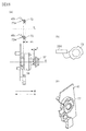
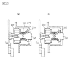
- FIG. 23 shows a sectional view of the drive connecting portion.
- the downstream drive transmission member 238 and the first bearing portion 245p (cylindrical outer surface) of the bearing 245 are engaged with each other. Further, the cylindrical portion 238q (cylindrical outer surface) of the downstream side drive transmission member 238 and the inner diameter portion 232q of the developing cover member 232 are engaged with each other. That is, both ends of the downstream drive transmission member 238 are rotatably supported by the bearing member 245 and the developing cover member 232.
- the cylindrical portion 237p (cylindrical outer surface) of the upstream drive transmission member 237 and the hole portion 232p of the developing cover member 232 are engaged with each other. Accordingly, the upstream drive transmission member 237 is supported so as to be slidable (rotatable) with respect to the developing cover member 232.
- the first bearing portion 245p (cylindrical outer surface) of the bearing member 245, the inner diameter portion 232q of the developing cover member 232, and the hole portion 232p are arranged on the same straight line as the rotation center X of the developing unit 9. That is, the upstream drive transmission member 237 is supported to be rotatable about the rotation center X of the developing unit 9. Further, as described above, the cylindrical portion 237m of the upstream drive transmission member 237 and the hole 238m of the downstream drive transmission member 238 are engaged. As a result, the downstream drive transmission member 238 is also supported so as to be rotatable about the rotation center X of the developing unit 9.
- the sectional view of the drive connecting portion shown in FIG. 23A shows a state where the claw 238a of the downstream drive transmission member 238 and the claw 237a of the upstream drive transmission member 237 are engaged with each other.
- 23B shows a state in which the claw 238a of the downstream drive transmission member 238 and the claw 237a of the upstream drive transmission member 237 are separated from each other.
- FIGS. FIG. 24C shows a perspective view of the configuration of the drive connecting portion. In FIG. 24, some parts are not shown for the sake of explanation.
- FIG. 24A a pair of the upstream drive transmission member 237 and the downstream drive transmission member 238 and a pair of the release cam 272 and the developing cover member 232 are shown separately.
- the developing cover member 232 displays only a part including the abutting part 232r
- the driving side cartridge cover member 224 displays only a part including the restricting part 224d.
- the claw 237a of the upstream drive transmission member 237 and the claw 238a of the downstream drive transmission member 238 are engaged with each other with an engagement amount q so that drive transmission is possible.
- the downstream drive transmission member 238 is engaged with the developing roller gear 69. Therefore, the driving force input from the apparatus main body 2 to the upstream drive transmission member 237 is transmitted to the developing roller gear 69 via the downstream drive transmission member 238. Thereby, the developing roller 6 is driven.
- the above state of each component is referred to as a contact position, and is also referred to as a development contact / drive transmission state.
- the position of the upstream drive transmission member 237 at this time is particularly referred to as a transmission position (drive transmission position, engagement position).
- the release cam 272 is in the maintenance position and urges the upstream drive transmission member 237 against the force of the spring 270. That is, the release cam 272 holds the upstream drive transmission member 237 in the transmission position.
- the developing unit 9 is centered on the rotation center X as described above. Is rotated in the direction of arrow K by an angle ⁇ 1. As a result, the developing roller 6 is separated from the drum 4 by a distance ⁇ 1.
- the developing cover member 232 incorporated in the developing unit 9 rotates in the arrow K direction by an angle ⁇ 1 in conjunction with the rotation of the developing unit 9.
- the release cam 272 is incorporated in the developing unit 9, but the force receiving portion 272b is engaged with the engaging portion 224d of the driving side cartridge cover member 224 as shown in FIG.
- the release cam 272 is restricted from rotating with respect to the drum unit 8. Further, the release cam 272 is pressed by the spring 270. Therefore, when the developing unit 9 rotates, the release cam 272 slides (translates) in the M direction of the X axis without rotating with respect to the drum unit 8, similarly to the release cam 72 of the first embodiment.
- the contact portion 272a of the release cam 272 has moved the contact portion 232r of the developing cover member 232 by p1 in the arrow M direction.
- p1 is smaller than q, and the claw 237a of the upstream drive transmission member 237 and the claw 238a of the downstream drive transmission member 238 are kept engaged with each other (FIG. 25A). . That is, it can be said that the upstream drive transmission member 237 is still in the transmission position.
- the driving force input from the apparatus main body 2 to the upstream drive transmission member 37 is transmitted to the developing roller 6 via the downstream drive transmission member 38 and the developing roller gear 69.
- the above-described state of each component is referred to as a development separation / drive transmission state.
- the force receiving portion 272b does not necessarily have to be in contact with the engaging portion 224d of the driving side cartridge cover member 224. That is, in the state 1, the force receiving portion 272b may be disposed with a gap with respect to the engaging portion 224d of the driving side cartridge cover member 224.
- FIG. 7C the structure of the drive connecting portion when the main body separating member 80 is moved by ⁇ 2 in the direction of the arrow F1 in the drawing from the developing separation / drive transmission state is shown in FIGS. This is shown in FIG.
- the developing cover member 232 rotates.
- the contact portion 272 a of the release cam 272 slides with respect to the contact portion 232 r of the developing cover member 232.
- the release cam 272 is movable only in the axial direction (arrow M and N directions) with its force receiving portion 272b engaged with the engaging portion 224d of the drive side cartridge cover member 224. It is regulated (see FIG. 22). Therefore, as a result, the release cam 272 and the upstream drive transmission member 237 slide and move in the direction of arrow M by the pressing force of the spring 70 (see FIGS. 26 and 26B).
- the position of the upstream drive transmission member 237 at this time is particularly referred to as a cutoff position (a drive cutoff position, an engagement release position, a drive connection cancellation position).
- the position of the release cam 272 at this time is particularly called an allowable position. The release cam 272 moves from the maintenance position to the allowable position, thereby allowing the upstream drive transmission member 237 to move to the blocking position by the force of the spring 270.
- the drive connecting portion is downstream of the claw 237a of the upstream drive transmission member 237 as shown in FIG.
- the side drive transmission member 238 is disengaged from the claw 238a.
- the developing unit 9 When the developing unit 9 is gradually rotated in the arrow H direction shown in FIG. 7 from the above state, the developing unit 9 is rotated by an angle ⁇ 1 (the state shown in FIG. 7B and FIG. 25). It becomes. In this state, the force receiving portion 272d of the release cam 272 engages with the engaging portion 224d of the drive side cartridge cover member 224, and the release cam slides only in the direction of arrow N. In conjunction with the movement of the release cam 272 in the direction of arrow N, the pressing surface 272c as the biasing portion of the release cam 272 presses the pressed surface 237c as the biased portion of the upstream drive transmission member 237 ( Energize).
- the upstream drive transmission member 237 moves in the arrow N direction against the pressing force of the spring 270, so that the claw 237a of the upstream drive transmission member 237 and the claw 238a of the downstream drive transmission member 238 engage with each other. .
- the driving force from the apparatus main body 2 is transmitted to the developing roller 6, and the developing roller 6 is rotationally driven. At this time, the developing roller 6 and the drum 4 are kept separated from each other.
- the developing roller 6 and the drum 4 can be brought into contact with each other by gradually rotating the developing unit 9 in the direction of arrow H shown in FIG.
- the force receiving portion 272b of the release cam 272 is configured to engage with the restricting portion 224d of the drive side cartridge cover member 224.
- the configuration is not necessarily limited thereto. The structure to do may be sufficient.
- a drive input member 90 provided at the drive side end of the developing unit 9 is a development drive output member 62 (62Y / 62M) as a main body side drive transmission member of the apparatus main body 2 shown in FIG. 62C and 62K) can be engaged. By this engagement, a driving force from a driving motor (not shown) provided in the apparatus main body 2 is transmitted.
- FIG. 27 is a perspective view of the process cartridge P as viewed from the driving side, and shows a state where the driving side cartridge cover member 324 and the developing cover member 332 are removed.
- the drive side cartridge cover member 324 is provided with an opening 324d.
- a coupling member 4a provided at the end of the photosensitive drum 4 is exposed from the opening 324d.
- the coupling member 4a is engaged with the drum drive output member 61 (61Y, 61M, 61C, 61K) of the apparatus main body 2 shown in FIG. 3B, and the drive motor (not shown) of the apparatus main body is engaged. It is configured to receive driving force.
- a drive input member 90 is rotatably provided at the end of the developing unit 9.
- the gear portion 90 g of the drive input member 90 is also engaged with the developing roller gear 69. Accordingly, the drive transmitted to the drive input member 90 is transmitted to the developing roller 6 via the developing roller gear 69.
- the drive connecting portion includes a bearing member 345, a release cam 372, a drive input member 90, a spring 70, a developing cover member 332, and a drive side cartridge cover member 324.
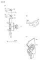
- FIG. 28 shows a sectional view of the drive connecting portion.
- the cylindrical portion 90p (cylindrical inner surface) of the drive input member 90 and the first bearing portion 345p (cylindrical outer surface) of the bearing member 345 are engaged with each other. Further, the cylindrical portion 90q (cylindrical outer surface) of the drive input member 90 and the inner diameter portion 332q of the developing cover member 332 are engaged with each other. That is, both ends of the drive input member 90 are rotatably supported by the bearing member 345 and the developing cover member 332.
- the first bearing portion 345p (cylindrical outer surface) of the bearing member 345, the inner diameter portion 332q of the developing cover member 332, and the hole portion 332p are arranged on the same straight line as the rotation center X of the developing unit 9. That is, the drive input member 90 is supported so as to be rotatable about the rotation center X of the developing unit 9.
- the sectional view of the drive connecting portion shown in FIG. 28A shows a state where the drive input member 90 and the development drive output member 62 as the main body side drive transmission member of the apparatus main body 2 are engaged with each other.
- 28B shows a state where the drive input member 90 and the development drive output member 62 of the apparatus main body 2 are separated from each other.
- FIG. 29B is a perspective view of the configuration of the drive connecting portion. In FIG. 29, some parts are not shown for the sake of explanation.
- FIG. 29A a pair of the drive input member 90 and the development drive output member 62 of the apparatus main body 2 and a pair of the release cam 372 and the bearing member 345 are separately shown.
- FIG. 29A a pair of the drive input member 90 and the development drive output member 62 of the apparatus main body 2 and a pair of the release cam 372 and the bearing member 345 are separately shown.
- the bearing member 345 displays only a part including the contact part 345r
- the cleaning container 326 displays only a part including the restriction part 326d.
- the drive input member 90 and the development drive output member 62 of the apparatus main body 2 are engaged with each other with an engagement amount q so that drive input is possible. Further, as described above, the drive input member 90 is engaged with the developing roller gear 69. Therefore, the driving force input from the apparatus main body 2 to the driving input member 90 is transmitted to the developing roller gear 69 and the developing roller 6 is driven.
- the above state of each component is referred to as a contact position, and is also referred to as a development contact / drive transmission state.
- the position of the drive input member 90 at this time is particularly referred to as a transmission position (drive transmission position, engagement position).
- the release cam 372 is in the maintenance position and biases the drive input member 90 against the force of the spring 70. That is, the release cam 372 holds the drive input member 90 in the transmission position.
- the developing unit 9 is centered on the rotation center X as described above. Is rotated in the direction of arrow K by an angle ⁇ 1. As a result, the developing roller 6 is separated from the drum 4 by a distance ⁇ 1.
- the bearing member 345 incorporated in the developing unit 9 rotates in the arrow K direction by an angle ⁇ 1 in conjunction with the rotation of the developing unit 9.
- the release cam 372 is incorporated in the developing unit 9, but the force receiving portion 372b is engaged with the engaging portion 326d of the cleaning container 326 as shown in FIG. Further, it is pressed by the spring 70.
- the release cam 372 does not rotate and slides in the N direction of the X axis, like the release cam 72 of the first embodiment.
- the contact portion 372a of the release cam 372 has moved the contact portion 345r of the bearing member 345 by p1 in the arrow N direction.
- p1 becomes a movement amount smaller than q, and the claw 90a of the drive input member 90 and the development drive output member 62 of the apparatus main body 2 are kept engaged with each other (FIG. 30A). Therefore, the driving force input from the apparatus main body 2 to the driving input member 90 is transmitted to the developing roller 6 via the developing roller gear 69.
- each component is referred to as a development separation / drive transmission state.
- the force receiving portion 372b does not necessarily have to be in contact with the engaging portion 326d of the cleaning container 326. That is, in the state 1, the force receiving portion 372b may be disposed with a gap with respect to the engaging portion 326d of the cleaning container 326. In this case, during the operation from the state 1 to the state 2, there is no gap between the force receiving portion 372b and the engaging portion 326d of the cleaning container 326, and the force receiving portion 372b becomes the engaging portion 326d of the cleaning container 326. It will abut. [State 3]
- FIG. 7C the structure of the drive connecting portion when the main body separating member 80 moves by ⁇ 2 in the direction of the arrow F1 in the drawing from the developing separation / drive transmission state is shown in FIGS. It is shown in 31 (b).
- the bearing member 345 rotates in conjunction with the rotation of the developing unit 9 by the angle ⁇ 2 (> ⁇ 1).
- the contact portion 372a of the release cam 372 slides with respect to the contact portion 345r of the bearing member 345.
- the release cam 372 is restricted so that the force receiving portion 372b engages with the engaging portion 326d of the cleaning container 326 so as to be movable only in the axial direction (arrow M and N directions). (See FIG. 13). Therefore, as a result, the release cam 372 and the drive input member 90 slide and move in the direction of arrow N by the moving amount p2 due to the pressing force of the spring 70. (See FIG. 31 and FIG. 28 (b)).
- the position of the drive input member 90 at this time is particularly referred to as a cut-off position (drive cut-off position, engagement release position, drive connection release position). Further, the position of the release cam 372 at this time is particularly called an allowable position.
- the release cam 372 allows the drive input member 90 to move to the blocking position by the force of the spring 70 by moving from the maintenance position to the allowable position.
- the drive connecting portion is a developing drive between the drive input member 90 and the apparatus main body 2 as shown in FIG. The engagement with the output member 62 is released.
- the developing unit 9 When the developing unit 9 is gradually rotated in the arrow H direction shown in FIG. 7 from the above state, the developing unit 9 is rotated by an angle ⁇ 1 (the state shown in FIG. 7B and FIG. 30). It becomes. In this state, the force receiving portion 372d of the release cam 372 engages with the engaging portion 326d of the cleaning container 326, and the release cam 372 slides only in the arrow M direction. In conjunction with the movement of the release cam 372 in the direction of the arrow M, the pressing surface 372c as the biasing portion of the release cam 372 presses (attaches) the pressed surface 90c as the biased portion of the drive input member 90. ).
- the drive input member 90 moves in the arrow M direction against the pressing force of the spring 70, whereby the drive input member 90 and the development drive output member 62 of the apparatus main body 2 are engaged with each other.
- the driving force from the apparatus main body 2 is transmitted to the developing roller 6, and the developing roller 6 is rotationally driven. At this time, the developing roller 6 and the drum 4 are kept separated from each other.
- the developing roller 6 and the drum 4 can be brought into contact with each other by gradually rotating the developing unit 9 in the direction of arrow H shown in FIG.
- the force receiving portion 372b of the release cam 372 is configured to be engaged with the restricting portion 326d of the cleaning container 326.
- the configuration is not necessarily limited thereto.
- the force receiving portion 372b is engaged with the drive side cartridge cover member 324.
- the structure to do may be sufficient.
- This embodiment is characterized in that an elastic member such as the spring 70 shown in the first embodiment is not used to move the drive transmission member (downstream drive transmission member 438) and the release member (release cam 472). [Configuration of drive connecting part]
- the drive connecting portion includes a bearing member 445, a release cam 472, a downstream drive transmission member 438, a developing cover member 432, an upstream drive transmission member 437, and a drive cartridge cover member 424.
- the release cam 472 is a part of the release mechanism, a coupling release member, and an action member.
- FIG. 33 shows the relationship between the release cam 472 and the bearing member 445. Also in this embodiment, the release cam 472 and the bearing member 445 are cam mechanisms that move the release cam 472 in accordance with the rotation operation of the developing unit 9.
- the release cam 472 has a substantially ring-shaped ring portion 472j.
- the ring portion 472j has a lever portion 472i as a second guided portion
- the bearing member 445 has a guide groove 445i as a second guide portion.
- the guide groove 445i is configured to be slidable with respect to the lever portion 472i.
- the release cam 472 is slidably moved in the axial direction with respect to the bearing member 445 and the developing unit 9, and is also supported so as to be rotatable in the rotational direction about the axis X.
- FIG. 34 shows the configuration of the release cam 472 and the restricting portion 426d provided in the cleaning container 426.
- the restricting portion 426d provided in the cleaning container 426 is installed inside the cleaning container, but it may be installed anywhere in the cleaning container 426 depending on the shape of the cleaning container 426.
- the lever portion 472 i of the release cam 472 receives a force from the cleaning container 426 by engaging with a restricting portion 426 d as a part of the second guide portion of the cleaning container 426.
- the lever portion 472 i protrudes from the developing cover member 432 and engages with the restriction portion 426 d of the cleaning container 426.
- the release cam 472 is slidable only in the axial direction (arrow M and N directions) with respect to the drive side cartridge cover member 424. It has become. Further, the outer diameter portion 432 a of the cylindrical portion 432 b of the developing cover member 432 is configured to slide with the sliding portion 424 a (cylindrical inner surface) of the driving side cartridge cover member 424. That is, the outer diameter portion 432a is rotatably coupled to the sliding portion 424a.
- the release cam 472 is engaged with both the guide groove 445i (cam groove) of the bearing member 445 and the restriction portion 426d of the cleaning container 426. That is, the release cam 472 is slidable (rotatable) with respect to the developing unit 9 in the axial direction (arrow M and N directions) and the rotational direction about the axis X. The release cam 472 is slidable (rotatable) in the axial direction (directions of arrows M and N) with respect to the drum unit 8 and the drive side cartridge cover member 424 fixed to the drum unit 8. Yes.
- FIG. 35 shows a sectional view of the drive connecting portion.
- the cylindrical portion 438p (cylindrical inner surface) of the downstream drive transmission member 438 and the first bearing portion 445p (cylindrical outer surface) of the bearing 445 are engaged with each other. Further, the cylindrical surface 438c of the downstream drive transmission member 438 is engaged with the surface 472c of the release cam 472, and the cylindrical surface 438d of the downstream drive transmission member 438 is engaged with the surface 472d of the release cam 472. . Thereby, the downstream drive transmission member 438 is restricted from moving in the axis X direction by the release cam 472. Further, the cylindrical portion 438q (cylindrical outer surface) of the downstream side drive transmission member 438 and the inner diameter portion 432q of the developing cover member 432 are engaged with each other. That is, both ends of the downstream drive transmission member 438 are rotatably supported by the bearing member 445 and the developing cover member 432.
- the cylindrical portion 437p (cylindrical outer surface) of the upstream drive transmission member 437 and the hole portion 432q of the developing cover member 432 are engaged with each other. Further, the main body side cylindrical portion 437q of the upstream side drive transmission member 437 and the coupling hole 424e of the drive side cartridge cover member 424 are engaged with each other. Accordingly, the upstream drive transmission member 437 is supported so as to be slidable (rotatable) with respect to the developing cover member 432 and the drive cartridge cover member 424.
- first bearing portion 445 p (cylindrical outer surface) of the bearing member 445, the inner diameter portion 432 q of the developing cover member 432, and the coupling hole 424 e are arranged on the same straight line as the rotation center X of the developing unit 9. . That is, the upstream drive transmission member 437 is supported to be rotatable about the rotation center X of the developing unit 9.
- FIG. 36B shows a perspective view of the configuration of the drive connecting portion. In FIG. 36, some parts are not shown for the sake of explanation.
- FIG. 36A a pair of the upstream drive transmission member 437 and the downstream drive transmission member 438 and a pair of the release cam 472 and the bearing member 445 are shown separately.
- FIG. 36A a pair of the upstream drive transmission member 437 and the downstream drive transmission member 438 and a pair of the release cam 472 and the bearing member 445 are shown separately.
- the bearing member 445 displays only a part including the guide groove 445i
- the cleaning container 426 displays only a part including the restricting portion 426d.
- the lever portion 472i of the release cam 472 is in a state of being sandwiched at a position closest to the drive side cartridge cover member 424 in the guide groove 445i of the bearing member 445.
- the upstream drive transmission member 437 and the downstream drive transmission member 438 are engaged with each other with an engagement amount q so that drive transmission is possible. Further, as described above, the downstream drive transmission member 438 is engaged with the developing roller gear 69 (see FIG. 59).
- each component is referred to as a contact position, and is also referred to as a development contact / drive transmission state.
- the position of the downstream drive transmission member 438 at this time is particularly referred to as a transmission position (drive transmission position, engagement position). Further, the position of the release cam 472 at this time is particularly referred to as a first maintenance position (engagement maintenance position, drive connection maintenance position). When the release cam 472 is in the first maintenance position, the downstream drive transmission member 438 is held in the transmission position by the urging portion (pressing surface 472c) of the downstream drive transmission member 438. [State 2]
- the developing unit 9 is centered on the rotation center X as described above. Is rotated in the direction of arrow K by an angle ⁇ 1. As a result, the developing roller 6 is separated from the drum 4 by a distance ⁇ 1.
- the release cam 472 and the bearing member 445 incorporated in the developing unit 9 rotate in the arrow K direction by an angle ⁇ 1 in conjunction with the rotation of the developing unit 9.
- the release cam 472 is incorporated in the developing unit 9, but the lever portion 472i is engaged with the engaging portion 426d of the cleaning container 426 as shown in FIG.
- the release cam 472 does not rotate with respect to the drum unit.
- the lever portion 472i slides between the guide grooves 445i, the release cam 472 slides in the N direction of the X axis.
- the lever portion 472i slides in the guide groove 445i
- the lever portion 472i slides in the N direction of the X axis by contacting the surface 445b of the guide groove 445i.
- the surface 445 b is a force applying unit that applies a force in the N direction to the release cam 472.
- the contact portion of the lever portion 472i that contacts the surface 455b is a force receiving portion that receives force from the force receiving portion.
- the surface 445b is an inclined surface (inclined portion) that is inclined with respect to the moving direction (rotating direction) of the developing unit 9.
- the surface 445b is also a cam surface (cam portion) that converts a force that moves the developing unit 9 relative to the drum unit into a force that biases the release cam 472 and the downstream drive transmission member 438 in the X-axis direction. That is, when the groove 445i moves relative to the lever portion 472i of the release cam 472 in accordance with the rotation of the developing unit, the lever portion 472i contacts the surface 445b and receives a force. This force causes the release cam 472 and the downstream drive transmission member 438 to move along the X axis.
- the pressing surface (biasing portion, force applying portion) 472d of the release cam 472 urges the downstream drive transmission member 438 in the N direction to move the distance p1.
- p1 is a movement amount smaller than q, and the upstream drive transmission member 437 and the downstream drive transmission member 438 are kept engaged with each other (FIG. 37A). Therefore, the driving force input from the apparatus main body 2 to the upstream drive transmission member 437 is transmitted to the developing roller 6 via the downstream drive transmission member 438 and the developing roller gear 69.
- the above-described state of each component is referred to as a development separation / drive transmission state. In the state 1 described above, the lever portion 472i does not necessarily have to be in contact with the engaging portion 426d of the cleaning container 426.
- the lever portion 472i may be disposed with a gap with respect to the engaging portion 426d of the cleaning container 426. In this case, during the operation from the state 1 to the state 2, there is no gap between the lever portion 472i and the engaging portion 426d of the cleaning container 426, and the lever portion 472i contacts the engaging portion 426d of the cleaning container 426. It will be. [State 3]
- FIG. 7C the structure of the drive connecting portion when the main body separation member 80 is moved by ⁇ 2 in the direction of the arrow F1 in the drawing from the development separation / drive transmission state is shown in FIGS. It is shown in 38 (b).
- the bearing member 445 rotates in conjunction with the rotation of the developing unit 9 by the angle ⁇ 2 (> ⁇ 1).
- the lever portion 472 i of the release cam 472 slides with respect to the guide groove portion 445 i of the bearing member 445.
- the release cam 472 is restricted so that its lever portion 472i engages with the engaging portion 426d of the cleaning container 426 so as to be movable only in the axial direction (arrow M and N directions). (See FIG. 34).
- the lever 472i slides in the groove 445i, the lever 472i receives a force in the arrow N direction from the surface 445b of the groove 445i.
- the release cam 472 and the downstream drive transmission member 438 slide in the direction of arrow N by the movement amount p2. (See FIG. 38 and FIG. 38 (b)). That is, the pressing surface 472d (FIG. 35B) of the release cam 472 moves the downstream drive transmission member 438 by the movement amount p2.
- the position of the downstream side drive transmission member 438 at this time is particularly referred to as a cutoff position (a drive cutoff position, an engagement release position, a drive connection cancellation position).
- the position of the release cam 472 at this time is particularly referred to as a second maintenance position (allowable position).
- the drive connecting portion is connected to the upstream drive transmission member 437 and the downstream drive transmission as shown in FIG. The engagement with the member 438 is released.
- the developing unit 9 When the developing unit 9 is gradually rotated in the direction of arrow H shown in FIG. 7 from the above state, the developing unit 9 is rotated by the angle ⁇ 1 (the state shown in FIG. 7B and FIG. 37). It becomes. In this state, the lever portion 472i of the release cam 472 engages with the engagement portion 426d of the cleaning container 426, and the release cam 472 slides only in the direction of arrow M along the guide groove 445i of the bearing member 445. That is, in the process in which the lever 472i of the release cam 472 slides in the groove 445i, the lever 472i receives a force in the direction of arrow M from the surface 445a of the groove 445i. With this force, the release cam 472 moves in the arrow M direction.
- the surface 445a is a force applying portion for applying force to the release cam 472, and the contact portion of the lever 472i that contacts the surface 455a is a force receiving portion that receives force from the force applying portion.
- the surface 455a is a cam portion (cam surface) that converts a force that moves the developing unit 9 relative to the drum unit into a force that biases the release cam 472 and the downstream transmission member 438.
- the surface 445a is also an inclined surface (inclined portion) that is inclined with respect to the rotation direction of the developing unit.
- the surface 445a faces the surface 445b with a gap. That is, the cam groove (guide groove 445i) is formed by the surface 445a and the surface 445b.
- the pressing surface 472c as the urging portion of the release cam 472 presses the pressed surface 438c as the urged portion of the downstream drive transmission member 438.
- the pressing surface 472 c is a second urging portion that urges the downstream drive transmission member 438.
- the upstream drive transmission member 437 and the downstream drive transmission member 438 are engaged with each other when the downstream drive transmission member 438 moves in the direction of arrow M by the urging of the pressing surface 472c.
- the driving force from the apparatus main body 2 is transmitted to the developing roller 6, and the developing roller 6 is rotationally driven. At this time, the developing roller 6 and the drum 4 are kept separated from each other.
- the developing roller 6 and the drum 4 can be brought into contact with each other by gradually rotating the developing unit 9 in the direction of arrow H shown in FIG.
- the moving member (release cam 472) and the guide groove 445i move the downstream drive transmission member 438 to change the state of drive transmission.
- the release cam 472 and the guide groove 445 i are cam mechanisms that convert the rotation operation of the developing unit 9 into the movement operation of the downstream drive transmission member 438.
- the force generated by the contact between the surface (cam) 455b of the guide groove 445i and the lever portion 472i moves the downstream drive transmission member 438 to the cutoff position and cuts the drive transmission.
- the force generated by the contact between the surface 455a and the lever portion 472i moves the downstream drive transmission member 438 to the transmission position, thereby ensuring the drive transmission.
- release cam 472 that actually moves the downstream drive transmission member 438. At least a part of the downstream drive transmission member 438 is disposed between the pressing surface 472c and the pressing surface 472d of the release cam. Thus, when the release cam 472 moves, the downstream drive transmission member 438 is urged from the release cam 472 to move.
- the lever portion 472i of the release cam 472 is configured to engage with the restricting portion 426d of the cleaning container 426.
- this is not necessarily limited, and for example, the lever portion 472i engages with the drive side cartridge cover member 424. It may be configured.
- the drive connecting portion includes a bearing member 545, a downstream drive transmission member 538, a developing cover member 532, a release cam 572, an upstream drive transmission member 537, and a drive cartridge cover member 524.
- the release cam 572 is a part of the release mechanism, a coupling release member, and an action member.
- the release cam 572 shows the relationship between the release cam 572 and the bearing member 545.
- parts between the release cam 572 and the bearing member 545 are not shown.
- the guide groove 545i as the second guide portion of the bearing member 545 is cut toward the drive side cartridge cover member 532 when separated.
- the guide groove 545i is configured such that the lever portion 572i can slide.
- the release cam 572 is slidably movable in the axial direction with respect to the bearing member 545 and the developing unit 9 and is also supported so as to be rotatable in the rotation direction about the axis X.
- the guide groove is provided in the bearing member 545.
- the guide groove may be provided in the developing cover member 532 and the driving side cartridge cover member 524.
- FIG. 41 shows a sectional view of the drive connecting portion.
- the cylindrical portion 538p (cylindrical inner surface) of the downstream drive transmission member 538 and the first bearing portion 445p (cylindrical outer surface) of the bearing 545 are engaged with each other.
- the cylindrical portion 538q (cylindrical outer surface) of the downstream drive transmission member 538 and the inner diameter portion 532q of the developing cover member 532 are engaged with each other. That is, both ends of the downstream drive transmission member 538 are rotatably supported by the bearing member 545 and the developing cover member 532.
- the cylindrical portion 537p (cylindrical outer surface) of the upstream drive transmission member 537 and the hole portion 532q of the developing cover member 532 are engaged with each other. Further, the surface 537c of the cylindrical portion of the upstream drive transmission member 537 is engaged with the surface 572c of the release cam 572, and the surface 537d of the cylindrical portion of the upstream drive transmission member 537 is engaged with the surface 572d of the release cam 572, respectively. . Thereby, the upstream drive transmission member 537 is restricted from moving in the direction of the axis X by the release cam 572.
- the upstream drive transmission member 537 is supported so as to be slidable (rotatable) with respect to the developing cover member 532 and the drive cartridge cover member 524.
- the first bearing portion 545p (cylindrical outer surface) of the bearing member 545, the inner diameter portion 532q of the developing cover member 532, the release cam 572, and the coupling hole 524e are on the same straight line as the rotation center X of the developing unit 9. Has been placed. That is, the upstream drive transmission member 537 is supported to be rotatable about the rotation center X of the developing unit 9.
- FIG. 7A the main body separation member 80 and the force receiving portion 45a of the bearing member 45 are separated with a gap d.
- the drum 4 and the developing roller 6 are in contact with each other.
- This state is referred to as state 1 of the main body separation member 80.
- the structure of the drive connecting portion at this time is schematically shown in FIG. FIG. 42B shows a perspective view of the configuration of the drive connecting portion. In FIG. 42, some parts are not shown for the sake of explanation.
- FIG. 42A a pair of the upstream drive transmission member 537 and the downstream drive transmission member 538, and a pair of the release cam 572 and the bearing member 545 are shown separately.
- FIG. 42A a pair of the upstream drive transmission member 537 and the downstream drive transmission member 538, and a pair of the release cam 572 and the bearing member 545 are shown separately.
- FIG. 42A a pair of the upstream drive transmission member 537 and the downstream drive transmission member 538, and a pair of the release cam 572 and the bearing
- the bearing member 545 displays only a part including the guide groove 545i
- the cleaning container 526 displays only a part including the restricting portion 526d.
- the lever portion 572 i of the release cam 572 is in a state of being sandwiched between the guide grooves 545 i of the bearing member 545 and the position farthest from the drive side cartridge cover member 524.
- the upstream drive transmission member 537 and the downstream drive transmission member 538 are engaged with each other with an engagement amount q so that drive transmission is possible. Further, as described above, the downstream drive transmission member 538 is engaged with the developing roller gear 69 (see FIG. 59).
- FIG. 7B the structure of the drive connecting portion when the main body separating member 80 is moved by ⁇ 1 in the direction of the arrow F1 in the drawing from the developing contact / drive transmission state is shown in FIGS. It is shown in 43 (b).
- the developing unit 9 rotates about the rotation center X in the arrow K direction by the angle ⁇ 1.
- the developing roller 6 is separated from the drum 4 by a distance ⁇ 1.
- the release cam 572 and the bearing member 545 incorporated in the developing unit 9 rotate in the arrow K direction by an angle ⁇ 1 in conjunction with the rotation of the developing unit 9.
- the release cam 572 is incorporated in the developing unit 9, but the lever portion 572i is engaged with the engaging portion 526d of the cleaning container 526 as shown in FIG. Further, when the developing unit 9 is rotated by the guide groove 545i of the bearing member 545, the release cam 572 does not rotate but the lever portion 572i slides between the guide grooves 545i, so that it slides in the M direction of the X axis. . At this time, as shown in FIGS. 43 (a) and 43 (b), the lever portion 572i of the release cam 572 has moved the guide portion 545i of the bearing member 545 by p1 in the arrow M direction.
- p1 is a movement amount smaller than q, and the upstream drive transmission member 537 and the downstream drive transmission member 538 are kept engaged with each other (FIG. 43A). Therefore, the driving force input from the apparatus main body 2 to the upstream drive transmission member 537 is transmitted to the developing roller 6 via the downstream drive transmission member 538 and the developing roller gear 69.
- the above-described state of each component is referred to as a development separation / drive transmission state.
- the lever portion 572i does not necessarily have to be in contact with the engaging portion 526d of the cleaning container 526. That is, in the state 1, the lever portion 572i may be disposed with a gap with respect to the engaging portion 526d of the cleaning container 526.
- FIG. 7C the structure of the drive connecting portion when the main body separation member 80 is moved by ⁇ 2 in the direction of the arrow F1 in the drawing from the development separation / drive transmission state is shown in FIGS. 44 (b).
- the bearing member 545 rotates in conjunction with the rotation of the developing unit 9 at the angle ⁇ 2 (> ⁇ 1).
- the lever portion 572i of the release cam 572 slides with respect to the guide groove portion 545i of the bearing member 545 and receives force from the groove portion 544i.
- the release cam 572 is restricted so that the lever portion 572i is engaged with the engaging portion 526d of the cleaning container 526 so as to be movable only in the axial direction (arrow M and N directions). . Therefore, as a result, the release cam 572 and the downstream drive transmission member 538 slide in the direction of arrow M by the movement amount p2. (See FIG. 44 and FIG. 44 (b)).
- the drive connecting portion is connected to the upstream side drive transmission member 537 and the downstream side drive transmission as shown in FIG. The engagement with the member 538 is released.
- the developing unit 9 When the developing unit 9 is gradually rotated in the direction of arrow H shown in FIG. 7 from the above state, the developing unit 9 is rotated by an angle ⁇ 1 (the state shown in FIG. 7B and FIG. 43). It becomes. In this state, the lever portion 572i of the release cam 572 engages with the engagement portion 526d of the cleaning container 526, and the release cam 572 slides only in the arrow N direction along the guide groove 545i of the bearing member 545. In conjunction with the movement of the release cam 572 in the direction of arrow N, the pressing surface 572c as the biasing portion of the release cam 572 presses the pressed surface 537c as the biased portion of the upstream drive transmission member 537. (Energize).
- the upstream drive transmission member 537 moves in the arrow N direction, so that the upstream drive transmission member 537 and the downstream drive transmission member 538 are engaged with each other.
- the driving force from the apparatus main body 2 is transmitted to the developing roller 6, and the developing roller 6 is rotationally driven. At this time, the developing roller 6 and the drum 4 are kept separated from each other.
- the developing roller 6 and the drum 4 can be brought into contact with each other by gradually rotating the developing unit 9 in the direction of arrow H shown in FIG.
- the lever portion 572i of the release cam 572 is configured to engage with the restricting portion 526d of the cleaning container 526.
- this is not necessarily limited, and for example, the lever portion 572i of the release cam 572 engages with the drive side cartridge cover member 524. It may be configured.
- the release cam 472 moves the downstream drive transmission member to switch the drive connection state between the downstream drive transmission member and the upstream drive transmission member.
- the release cam moves the drive transmission member (drive input member 690) on the cartridge side to switch the drive connection state with the drive transmission member (development drive output member 62) on the main body side.
- the drive connecting portion includes a bearing member 645, a release cam 672, a drive input member 690, a developing cover member 632, and a drive side cartridge cover member 624.
- the relationship between the release cam 672 and the bearing member 645, and the configuration of the release cam 672 and the restricting portion 626d provided in the cleaning container 626 are the same as those in the fourth embodiment, and are omitted here.
- FIG. 46 shows a sectional view of the drive connecting portion.
- the cylindrical portion 690p (cylindrical inner surface) of the drive input member 690 and the first bearing portion 645p (cylindrical outer surface) of the bearing 645 are engaged with each other. Further, the surface 690 c of the cylindrical portion of the drive input member 690 is engaged with the surface 672 c of the release cam 672 and the surface 690 d of the cylindrical portion of the drive input member 690 is engaged with the surface 672 d of the release cam 672. As a result, the drive input member 690 is restricted from moving in the direction of the axis X by the release cam 672.
- cylindrical portion 690q (cylindrical outer surface) of the drive input member 690 and the inner diameter portion 632q of the developing cover member 632 are engaged with each other. That is, the drive input member 690 is rotatably supported by the bearing member 645 and the developing cover member 632 at both ends thereof.
- first bearing portion 645 p (cylindrical outer surface) of the bearing member 645 and the inner diameter portion 632 q of the developing cover member 632 are arranged on the same straight line as the rotation center X of the developing unit 9. That is, the drive input member 690 is supported so as to be rotatable about the rotation center X of the developing unit 9.
- the sectional view of the drive connecting portion shown in FIG. 46A shows a state where the drive input member 690 and the development drive output member 62 as the main body side drive transmission member of the apparatus main body 2 are engaged with each other.
- 46B shows a state where the drive input member 690 and the development drive output member 62 of the apparatus main body 2 are separated from each other.
- FIG. 7A the main body separation member 80 and the force receiving portion 45a of the bearing member 45 are separated with a gap d. At this time, the drum 4 and the developing roller 6 are in contact with each other. This state is referred to as state 1 of the main body separation member 80.
- the configuration of the drive connecting portion at this time is schematically shown in FIG. FIG. 47B shows a perspective view of the configuration of the drive connecting portion. In FIG. 47, some parts are not shown for the sake of explanation.
- FIG. 47A a pair of the drive input member 690 and the development drive output member 62 of the apparatus main body 2 and a pair of the release cam 672 and the bearing member 645 are separately shown.
- the bearing member 645 displays only a part including the guide groove 645i
- the cleaning container 626 displays only a part including the restricting portion 626d.
- the lever portion 672i of the release cam 672 is sandwiched at a position closest to the drive side cartridge cover member 624 in the guide groove 645i of the bearing member 645.
- the drive input member 690 and the development drive output member 62 of the apparatus main body 2 are engaged with each other with an engagement amount q so that drive input is possible.
- the drive input member 690 is engaged with the developing roller gear 69 (see FIG. 59). Therefore, the driving force input from the apparatus main body 2 to the driving input member 690 is transmitted to the developing roller gear 69. Thereby, the developing roller 6 is driven.
- the above state of each component is referred to as a contact position, and is also referred to as a development contact / drive transmission state. [State 2]
- FIG. 7B the structure of the drive connecting portion when the main body separation member 80 is moved by ⁇ 1 in the direction of arrow F1 in the drawing from the developing contact / drive transmission state is shown in FIGS. 48 (b).
- the release cam 672 is incorporated in the developing unit 9, but the lever portion 672i is engaged with the engaging portion 626d of the cleaning container 626 as shown in FIG. Further, when the developing unit 9 is rotated by the guide groove 645i of the bearing member 645, the release cam 672 does not rotate but the lever portion 672i slides between the guide grooves 645i, so that it slides in the N direction of the X axis. .
- FIGS. 48 (b) the structure of the drive connecting portion when the main body separation member 80 is moved by ⁇ 1 in the direction of arrow F1 in the drawing from the developing contact / drive transmission state is shown in FIGS. 48 (b).
- the release cam 672 is incorporated in the developing unit 9, but the lever portion 672i is engaged with the engaging portion 626d of
- the lever portion 672i of the release cam 672 has moved the guide portion 645i of the bearing member 645 by p1 in the arrow N direction.
- p1 becomes a movement amount smaller than q, and the drive input member 690 and the development drive output member 62 of the apparatus main body 2 are kept engaged with each other (FIG. 48A). Therefore, the driving force input from the apparatus main body 2 to the driving input member 690 is transmitted to the developing roller 6 via the developing roller gear 69.
- the above-described state of each component is referred to as a development separation / drive transmission state. In the state 1 described above, the lever portion 672i does not necessarily have to be in contact with the engaging portion 626d of the cleaning container 626.
- the lever portion 672i may be disposed with a gap with respect to the engaging portion 626d of the cleaning container 626.
- the ascending operation eliminates the gap between the lever portion 672i and the engaging portion 626d of the cleaning container 626, and the lever portion 672i contacts the engaging portion 626d of the cleaning container 626. Will be in touch.
- FIG. 7C the structure of the drive connecting portion when the main body separating member 80 is moved by ⁇ 2 in the direction of the arrow F1 in the drawing from the developing separation / drive transmission state is shown in FIGS. It is shown in 49 (b).
- the bearing member 645 rotates in conjunction with the rotation of the developing unit 9 at the angle ⁇ 2 (> ⁇ 1).
- the lever portion 672i of the release cam 672 slides with respect to the guide groove portion 645i of the bearing member 645 and receives force from the guide groove portion 645i.
- the release cam 672 is regulated so that the lever portion 672i can be engaged only with the engaging portion 626d of the cleaning container 626 so as to be movable only in the axial direction (arrow M and N directions). (See FIG. 49). Therefore, as a result, the release cam 672 and the drive input member 690 slide in the direction of arrow N by the movement amount p2. (See FIG. 49 (a) and FIG. 49 (b)).
- the drive connecting portion is a development drive of the drive input member 690 and the apparatus main body 2 as shown in FIG. The engagement with the output member 62 is released.
- the developing unit 9 When the developing unit 9 is gradually rotated in the arrow H direction shown in FIG. 7 from the above state, the developing unit 9 is rotated by an angle ⁇ 1 (the state shown in FIG. 7B and FIG. 48). It becomes. In this state, the lever portion 672i of the release cam 672 engages with the engagement portion 626d of the cleaning container 626, and the release cam 672 slides only in the direction of arrow M along the guide groove 645i of the bearing member 645. In conjunction with the movement of the release cam 672 in the direction of arrow M, the pressing surface 672c as the biasing portion of the release cam 672 presses the pressed surface 690c as the biased portion of the drive input member 690 (attachment). ).
- the drive input member 690 moves in the direction of arrow M, so that the drive input member 690 and the development drive output member 62 of the apparatus main body 2 are engaged with each other.
- the driving force from the apparatus main body 2 is transmitted to the developing roller 6, and the developing roller 6 is rotationally driven. At this time, the developing roller 6 and the drum 4 are kept separated from each other.
- the developing roller 6 and the drum 4 can be brought into contact with each other by gradually rotating the developing unit 9 in the direction of arrow H shown in FIG.
- the lever portion 672i of the release cam 672 is configured to engage with the restricting portion 626d of the cleaning container 626.
- this is not necessarily limited, and for example, the lever portion 672i engages with the drive side cartridge cover member 624. It may be configured.
- one end of the spring 70 contacts the developing cover member 32, and the other end of the spring 70 is the downstream drive transmission member 38. Touching.
- the downstream drive transmission member 38 rotates with respect to the spring 70. Then, friction occurs between the end of the spring 70 and the downstream drive transmission member 38. Due to this friction, there is a possibility that the portion of the downstream drive transmission member 38 that is in contact with the spring 70 is worn (scraped).
- the downstream drive transmission member 38 is made of a material that is resistant to wear, or the downstream drive transmission member 38 and the spring 70 are made of a material that can easily reduce the frictional force. It is possible to take. On the other hand, in this embodiment, a countermeasure different from these will be described.
- FIG. 50 and 51 is a configuration example in which the configuration of the first embodiment is partially changed.
- FIG. 51A shows a state in which the upstream drive transmission member 37 and the downstream drive transmission member 38 are coupled (coupled) and drive transmission is possible between them.
- FIG. 51 (b) shows a state in which the coupling between the two is eliminated, and no driving force (rotational force) is transmitted to the downstream drive transmission member 38 when the upstream drive transmission member 37 rotates.
- the cartridge of the present embodiment includes the downstream drive transmission member 38 and the spring 70 described in the first embodiment.
- a plate member (intervening member, relaxation member) 80 is sandwiched between the downstream drive transmission member 38 and the spring 70.
- the plate member 80 is an interposed member interposed between the downstream drive transmission member 38 and the spring 70, and is also a relaxation member for reducing the load applied to the downstream drive transmission member 38.
- the downstream drive transmission member 38 and the spring 70 are not in direct contact by the plate member 80. Therefore, when the downstream drive transmission member 38 rotates, friction generated between the downstream drive transmission member 38 and the spring 70 can be eliminated.
- the downstream drive transmission member 38 is configured to be rotatable with respect to the plate member 80. That is, when the downstream transmission member 38 receives a driving force from the upstream drive transmission member 37, the downstream drive transmission member 38 rotates with respect to the plate member 80. At this time, friction occurs between the downstream drive transmission member 38 and the plate member 80.
- the load that the downstream drive transmission member 38 receives from the plate member 80 in this embodiment is generally smaller than the load that the downstream drive transmission member 38 receives from the spring 70 in the first embodiment. This is because the area received by the downstream drive transmission member 38 and the plate member 80 in this embodiment is larger than the area where the downstream drive transmission member 38 contacts the spring 70 in the first embodiment. As a result, the pressure that the downstream drive transmission member 38 receives from the plate member 80 in this embodiment is smaller than the pressure that the downstream drive transmission member 38 receives from the spring 70 in the first embodiment. Thereby, even if friction occurs between the downstream drive transmission member 38 and the plate member 80, the wear of the downstream drive transmission member 38 can be reduced.
- a lubricant may be applied to the contact portion between the both.
- the present embodiment is a modification of the configuration of the first embodiment
- the configuration described in the second embodiment (see FIG. 23) and the third embodiment (see FIG. 28) may be modified in the same manner as the present embodiment. it can. Such a modification will be described below with reference to FIGS.
- FIG. 52 shows a state in which the upstream drive transmission member 237 and the downstream drive transmission member 238 are coupled (coupled) and drive transmission is possible between them.
- FIG. 52B shows a state in which the coupling between the two is eliminated, and no driving force (rotational force) is transmitted to the downstream drive transmission member 238 when the upstream drive transmission member 237 rotates.
- the plate member 180 and the plate member 181 are interposition members (relaxation members) similar to the plate member 80 described above. In the configuration of FIG. 52, the spring 70 does not directly contact the transmission members 237 and 238.
- a plate member 181 is also disposed between the spring 70 and the downstream drive transmission member 238. In this case, even if the spring 70 rotates with respect to the downstream drive transmission member 238, the frictional force applied between the downstream drive transmission member 238 and the plate member 181 is small.
- FIG. 53A shows a state in which the transmission member (drive input member 90) is in the advanced position (transmission position) where it has advanced toward the outside of the cartridge and is coupled (coupled) with the drive output member 62. Yes.
- FIG. 53B shows a state where the drive input member 90 is in the retracted position (blocking position) where it is retracted inside the cartridge, and the coupling with the drive output member 62 is eliminated.
- Example 3 one end of the spring 70 was in contact with the developing cover member 332 of the developing unit, and the other end of the spring 70 was in contact with the drive input member 90. In contrast, in the configuration shown in FIG. 53, the spring 70 does not contact the drive input member 90 but contacts the plate member 280.
- the plate member 280 has substantially the same configuration as the plate member 80.
- the drive input member 90 receives and receives a driving force from the apparatus main body and rotates, the drive input member 90 rotates with respect to the plate member 280.
- the load that the drive input member 90 receives from the plate member 280 is relatively small.
- each configuration shown in the present embodiment employs a thin plate-like member as the interposed member, but it is not necessary to have such a shape as long as wear of the transmission member can be suppressed.
- the interposition member is formed in a plate shape, the thickness of the interposition member can be suppressed, and the size of the cartridge and the image forming apparatus main body on which the cartridge is mounted can be suppressed.
- a process cartridge and an image forming apparatus capable of appropriately switching the drive to the developing roller are provided.
Landscapes
- Engineering & Computer Science (AREA)
- Computer Vision & Pattern Recognition (AREA)
- Physics & Mathematics (AREA)
- General Physics & Mathematics (AREA)
- Electrophotography Configuration And Component (AREA)
- Dry Development In Electrophotography (AREA)
Priority Applications (4)
| Application Number | Priority Date | Filing Date | Title |
|---|---|---|---|
| US16/118,703 US10534313B2 (en) | 2016-03-04 | 2018-08-31 | Process cartridge and image forming apparatus |
| US16/720,252 US10824110B2 (en) | 2016-03-04 | 2019-12-19 | Process cartridge and image forming apparatus |
| US17/024,904 US11175624B2 (en) | 2016-03-04 | 2020-09-18 | Process cartridge and image forming apparatus |
| US17/501,035 US11573524B2 (en) | 2016-03-04 | 2021-10-14 | Process cartridge and image forming apparatus |
Applications Claiming Priority (2)
| Application Number | Priority Date | Filing Date | Title |
|---|---|---|---|
| JP2016042554 | 2016-03-04 | ||
| JP2016-042554 | 2016-03-04 |
Related Child Applications (1)
| Application Number | Title | Priority Date | Filing Date |
|---|---|---|---|
| US16/118,703 Continuation US10534313B2 (en) | 2016-03-04 | 2018-08-31 | Process cartridge and image forming apparatus |
Publications (1)
| Publication Number | Publication Date |
|---|---|
| WO2017150741A1 true WO2017150741A1 (ja) | 2017-09-08 |
Family
ID=59744092
Family Applications (1)
| Application Number | Title | Priority Date | Filing Date |
|---|---|---|---|
| PCT/JP2017/009632 WO2017150741A1 (ja) | 2016-03-04 | 2017-03-03 | プロセスカートリッジおよび画像形成装置 |
Country Status (4)
| Country | Link |
|---|---|
| US (4) | US10534313B2 (zh) |
| JP (3) | JP6983518B2 (zh) |
| TW (3) | TWI799888B (zh) |
| WO (1) | WO2017150741A1 (zh) |
Cited By (1)
| Publication number | Priority date | Publication date | Assignee | Title |
|---|---|---|---|---|
| CN108845484A (zh) * | 2018-07-18 | 2018-11-20 | 中山市迪迈打印科技有限公司 | 动力传递装置 |
Families Citing this family (9)
| Publication number | Priority date | Publication date | Assignee | Title |
|---|---|---|---|---|
| JP5328230B2 (ja) * | 2008-06-10 | 2013-10-30 | キヤノン株式会社 | カートリッジ、及び、前記カートリッジを用いた電子写真画像形成装置 |
| BR122018074174B1 (pt) | 2014-11-28 | 2023-12-19 | Canon Kabushiki Kaisha | Cartucho montável a um conjunto principal de aparelho de um aparelho formador de imagem |
| WO2017150741A1 (ja) * | 2016-03-04 | 2017-09-08 | キヤノン株式会社 | プロセスカートリッジおよび画像形成装置 |
| JP7140562B2 (ja) | 2017-06-15 | 2022-09-21 | キヤノン株式会社 | カートリッジおよび電子写真画像形成装置 |
| JP7034651B2 (ja) * | 2017-09-28 | 2022-03-14 | キヤノン株式会社 | 画像形成装置 |
| JP7080678B2 (ja) | 2018-03-13 | 2022-06-06 | キヤノン株式会社 | カートリッジ |
| CN110231762B (zh) * | 2019-07-11 | 2024-05-24 | 珠海天威飞马打印耗材有限公司 | 驱动组件、处理盒及电子照相成像装置 |
| CN117908344A (zh) | 2019-08-09 | 2024-04-19 | 佳能株式会社 | 调色剂容器 |
| JP2022050266A (ja) * | 2020-09-17 | 2022-03-30 | キヤノン株式会社 | カートリッジ及び画像形成装置 |
Citations (5)
| Publication number | Priority date | Publication date | Assignee | Title |
|---|---|---|---|---|
| JPH086368A (ja) * | 1994-06-15 | 1996-01-12 | Seiko Epson Corp | カートリッジ、及び画像形成装置 |
| JP2001337511A (ja) * | 2000-05-26 | 2001-12-07 | Matsushita Electric Ind Co Ltd | カラー画像形成装置 |
| JP2003208024A (ja) * | 2002-01-15 | 2003-07-25 | Canon Inc | 駆動装置及びカラー画像形成装置 |
| JP2004126006A (ja) * | 2002-09-30 | 2004-04-22 | Canon Inc | 現像装置及び現像剤 |
| JP2005076734A (ja) * | 2003-08-29 | 2005-03-24 | Canon Inc | 駆動伝達装置及び画像形成装置 |
Family Cites Families (56)
| Publication number | Priority date | Publication date | Assignee | Title |
|---|---|---|---|---|
| JP3200141B2 (ja) | 1991-04-08 | 2001-08-20 | キヤノン株式会社 | 画像形成装置及び画像形成装置に着脱自在なプロセスカートリッジ |
| US5331373A (en) | 1992-03-13 | 1994-07-19 | Canon Kabushiki Kaisha | Image forming apparatus, process cartridge mountable within it and method for attaching photosensitive drum to process cartridge |
| JP3352155B2 (ja) | 1992-06-30 | 2002-12-03 | キヤノン株式会社 | プロセスカートリッジ及び画像形成装置 |
| US5966566A (en) | 1993-03-24 | 1999-10-12 | Canon Kabushiki Kaisha | Recycle method for process cartridge and image forming apparatus |
| JPH07319362A (ja) | 1994-05-19 | 1995-12-08 | Canon Inc | プロセスカートリッジの再生産方法及びプロセスカートリッジ |
| JPH10228222A (ja) | 1997-02-17 | 1998-08-25 | Canon Inc | プロセスカートリッジ及び電子写真画像形成装置 |
| JP3689552B2 (ja) | 1997-04-07 | 2005-08-31 | キヤノン株式会社 | トナーフレーム、プロセスカートリッジ、及び、電子写真画像形成装置 |
| JP3445124B2 (ja) | 1997-10-23 | 2003-09-08 | キヤノン株式会社 | プロセスカートリッジ |
| JP3437424B2 (ja) | 1997-10-27 | 2003-08-18 | キヤノン株式会社 | 現像装置及びプロセスカートリッジ及び電子写真画像形成装置 |
| JP3290619B2 (ja) | 1997-11-20 | 2002-06-10 | キヤノン株式会社 | プロセスカートリッジ及び電子写真画像形成装置 |
| JPH11161131A (ja) | 1997-11-29 | 1999-06-18 | Canon Inc | プロセスカートリッジ及び電子写真画像形成装置 |
| JPH11296051A (ja) | 1998-04-08 | 1999-10-29 | Canon Inc | プロセスカートリッジ |
| JP3768710B2 (ja) | 1999-01-28 | 2006-04-19 | キヤノン株式会社 | 現像装置、プロセスカートリッジ、及び、電子写真画像形成装置 |
| JP2000347492A (ja) | 1999-06-09 | 2000-12-15 | Canon Inc | 現像剤補給装置、現像装置及びこの現像装置を備える画像形成装置 |
| JP4612771B2 (ja) | 2000-11-28 | 2011-01-12 | キヤノン株式会社 | 端部部材、現像剤収納部及びプロセスカートリッジ |
| JP2002278415A (ja) | 2001-03-16 | 2002-09-27 | Canon Inc | プロセスカートリッジ及び電子写真画像形成装置 |
| JP4681762B2 (ja) | 2001-06-18 | 2011-05-11 | キヤノン株式会社 | カートリッジ |
| US6795671B2 (en) | 2002-01-15 | 2004-09-21 | Canon Kabushiki Kaisha | Image forming apparatus featuring switchable, contact and spaced, clutch-operated developing units |
| JP2003307993A (ja) | 2002-04-17 | 2003-10-31 | Canon Inc | 電子写真感光体ドラム、プロセスカートリッジ及び電子写真画像形成装置 |
| JP2003307992A (ja) | 2002-04-17 | 2003-10-31 | Canon Inc | プロセスカートリッジ及び電子写真画像形成装置 |
| JP4018517B2 (ja) | 2002-11-29 | 2007-12-05 | キヤノン株式会社 | 部品 |
| JP3950892B2 (ja) | 2004-01-30 | 2007-08-01 | キヤノン株式会社 | 電子写真画像形成装置 |
| JP4314150B2 (ja) | 2004-05-14 | 2009-08-12 | キヤノン株式会社 | 現像装置、及びプロセスカートリッジ |
| JP3970274B2 (ja) | 2004-03-31 | 2007-09-05 | キヤノン株式会社 | プロセスカートリッジ及び電子写真画像形成装置 |
| JP2005316192A (ja) | 2004-04-28 | 2005-11-10 | Canon Inc | 電子写真画像形成装置 |
| US20060008289A1 (en) | 2004-07-06 | 2006-01-12 | Canon Kabushiki Kaisha | Electrophotographic image forming apparatus and process cartridge |
| JP4617122B2 (ja) | 2004-09-08 | 2011-01-19 | キヤノン株式会社 | 現像剤搬送部材、現像装置、および、プロセスカートリッジ |
| JP3950883B2 (ja) | 2004-10-06 | 2007-08-01 | キヤノン株式会社 | 電子写真画像形成装置 |
| US7885554B2 (en) * | 2004-12-09 | 2011-02-08 | Seiko Epson Corporation | Developing device, image forming apparatus, image forming system, cartridge, developing unit and photoconductor unit |
| JP4681946B2 (ja) | 2005-05-27 | 2011-05-11 | キヤノン株式会社 | プロセスカートリッジ、現像カートリッジ及び電子写真画像形成装置 |
| US7660550B2 (en) | 2006-12-11 | 2010-02-09 | Canon Kabushiki Kaisha | Process cartridge and image forming apparatus |
| KR101079575B1 (ko) * | 2007-01-26 | 2011-11-03 | 삼성전자주식회사 | 현상유니트 구동장치 및 방법과, 이 구동장치를 채용한화상형성장치 |
| JP4839337B2 (ja) | 2008-05-27 | 2011-12-21 | キヤノン株式会社 | カートリッジ |
| US20100007788A1 (en) | 2008-07-09 | 2010-01-14 | Vizio, Inc. | Method and apparatus for managing non-used areas of a digital video display when video of other aspect ratios are being displayed |
| JP5371627B2 (ja) * | 2008-08-27 | 2013-12-18 | キヤノン株式会社 | 現像装置、現像カートリッジ、及び、電子写真画像形成装置 |
| JP2010084881A (ja) * | 2008-10-01 | 2010-04-15 | Kyocera Mita Corp | 駆動伝達装置及びこれを備えた画像形成装置 |
| JP5349999B2 (ja) * | 2009-02-16 | 2013-11-20 | キヤノン株式会社 | プロセスカートリッジおよび画像形成装置 |
| CN102378941B (zh) * | 2009-03-30 | 2014-03-12 | 佳能株式会社 | 显影剂供给容器和显影剂供给系统 |
| US8270877B2 (en) * | 2009-04-28 | 2012-09-18 | Brother Kogyo Kabushiki Kaisha | Image forming apparatus |
| EP2530532B1 (en) | 2010-01-28 | 2020-04-01 | Ninestar Corporation | Cartridge |
| JP4678891B1 (ja) * | 2010-07-05 | 2011-04-27 | キヤノン株式会社 | 電子写真画像形成装置 |
| CN110376861B (zh) * | 2012-06-15 | 2022-10-18 | 佳能株式会社 | 盒 |
| JP6202911B2 (ja) | 2012-09-07 | 2017-09-27 | キヤノン株式会社 | 画像形成装置、プロセスカートリッジ |
| JP5980064B2 (ja) | 2012-09-13 | 2016-08-31 | キヤノン株式会社 | 現像装置の製造方法及びプロセスカートリッジの製造方法 |
| JP6136372B2 (ja) * | 2013-03-04 | 2017-05-31 | ブラザー工業株式会社 | 現像カートリッジ |
| JP6376749B2 (ja) * | 2013-12-06 | 2018-08-22 | キヤノン株式会社 | プロセスカートリッジおよび電子写真画像形成装置 |
| CA2944346C (en) | 2014-04-01 | 2021-11-23 | Ict Global Systems Pty Limited | Internet protocol based audio alert system |
| JP6584138B2 (ja) | 2014-06-17 | 2019-10-02 | キヤノン株式会社 | 現像カートリッジ、プロセスカートリッジ及び画像形成装置 |
| BR122018074174B1 (pt) | 2014-11-28 | 2023-12-19 | Canon Kabushiki Kaisha | Cartucho montável a um conjunto principal de aparelho de um aparelho formador de imagem |
| RU2697424C2 (ru) | 2014-11-28 | 2019-08-14 | Кэнон Кабусики Кайся | Картридж и электрофотографическое устройство формирования изображения |
| JP6873604B2 (ja) | 2015-06-05 | 2021-05-19 | キヤノン株式会社 | プロセスカートリッジ、および、電子写真画像形成装置 |
| JP6289427B2 (ja) * | 2015-09-30 | 2018-03-07 | キヤノン株式会社 | カートリッジ及びカートリッジの製造方法 |
| WO2017150741A1 (ja) * | 2016-03-04 | 2017-09-08 | キヤノン株式会社 | プロセスカートリッジおよび画像形成装置 |
| KR20180017427A (ko) * | 2016-08-09 | 2018-02-21 | 에스프린팅솔루션 주식회사 | 현상 카트리지 및 이를 채용한 전자사진방식 화상형성장치 |
| JP6855284B2 (ja) | 2017-03-03 | 2021-04-07 | キヤノン株式会社 | カートリッジ及び画像形成装置 |
| JP7080678B2 (ja) | 2018-03-13 | 2022-06-06 | キヤノン株式会社 | カートリッジ |
-
2017
- 2017-03-03 WO PCT/JP2017/009632 patent/WO2017150741A1/ja active Application Filing
- 2017-03-03 TW TW110120802A patent/TWI799888B/zh active
- 2017-03-03 JP JP2017040841A patent/JP6983518B2/ja active Active
- 2017-03-03 TW TW108117902A patent/TWI733118B/zh active
- 2017-03-03 TW TW106107064A patent/TWI668533B/zh active
-
2018
- 2018-08-31 US US16/118,703 patent/US10534313B2/en active Active
-
2019
- 2019-12-19 US US16/720,252 patent/US10824110B2/en active Active
-
2020
- 2020-09-18 US US17/024,904 patent/US11175624B2/en active Active
-
2021
- 2021-09-10 JP JP2021147474A patent/JP7150959B2/ja active Active
- 2021-10-14 US US17/501,035 patent/US11573524B2/en active Active
-
2022
- 2022-09-22 JP JP2022151394A patent/JP7387850B2/ja active Active
Patent Citations (5)
| Publication number | Priority date | Publication date | Assignee | Title |
|---|---|---|---|---|
| JPH086368A (ja) * | 1994-06-15 | 1996-01-12 | Seiko Epson Corp | カートリッジ、及び画像形成装置 |
| JP2001337511A (ja) * | 2000-05-26 | 2001-12-07 | Matsushita Electric Ind Co Ltd | カラー画像形成装置 |
| JP2003208024A (ja) * | 2002-01-15 | 2003-07-25 | Canon Inc | 駆動装置及びカラー画像形成装置 |
| JP2004126006A (ja) * | 2002-09-30 | 2004-04-22 | Canon Inc | 現像装置及び現像剤 |
| JP2005076734A (ja) * | 2003-08-29 | 2005-03-24 | Canon Inc | 駆動伝達装置及び画像形成装置 |
Cited By (1)
| Publication number | Priority date | Publication date | Assignee | Title |
|---|---|---|---|---|
| CN108845484A (zh) * | 2018-07-18 | 2018-11-20 | 中山市迪迈打印科技有限公司 | 动力传递装置 |
Also Published As
| Publication number | Publication date |
|---|---|
| US10534313B2 (en) | 2020-01-14 |
| US10824110B2 (en) | 2020-11-03 |
| TW201800881A (zh) | 2018-01-01 |
| US20180373199A1 (en) | 2018-12-27 |
| TW202138939A (zh) | 2021-10-16 |
| US20220035309A1 (en) | 2022-02-03 |
| JP7387850B2 (ja) | 2023-11-28 |
| US20200125028A1 (en) | 2020-04-23 |
| TWI733118B (zh) | 2021-07-11 |
| JP2022174307A (ja) | 2022-11-22 |
| TWI799888B (zh) | 2023-04-21 |
| JP2017161904A (ja) | 2017-09-14 |
| TW201937316A (zh) | 2019-09-16 |
| US11573524B2 (en) | 2023-02-07 |
| US20210003965A1 (en) | 2021-01-07 |
| TWI668533B (zh) | 2019-08-11 |
| JP7150959B2 (ja) | 2022-10-11 |
| TW202328831A (zh) | 2023-07-16 |
| JP2021185440A (ja) | 2021-12-09 |
| JP6983518B2 (ja) | 2021-12-17 |
| US11175624B2 (en) | 2021-11-16 |
Similar Documents
| Publication | Publication Date | Title |
|---|---|---|
| WO2017150741A1 (ja) | プロセスカートリッジおよび画像形成装置 | |
| US11614710B2 (en) | Cartridge, process cartridge and electrophotographic image forming apparatus | |
| JP6992116B2 (ja) | プロセスカートリッジおよび画像形成装置 | |
| JP2021105742A (ja) | カートリッジ、プロセスカートリッジ、および、電子写真画像形成装置 | |
| TWI843483B (zh) | 匣及影像形成裝置 |
Legal Events
| Date | Code | Title | Description |
|---|---|---|---|
| NENP | Non-entry into the national phase |
Ref country code: DE |
|
| 121 | Ep: the epo has been informed by wipo that ep was designated in this application |
Ref document number: 17760202 Country of ref document: EP Kind code of ref document: A1 |
|
| 122 | Ep: pct application non-entry in european phase |
Ref document number: 17760202 Country of ref document: EP Kind code of ref document: A1 |