WO2017149792A1 - 吸収性物品 - Google Patents
吸収性物品 Download PDFInfo
- Publication number
- WO2017149792A1 WO2017149792A1 PCT/JP2016/065350 JP2016065350W WO2017149792A1 WO 2017149792 A1 WO2017149792 A1 WO 2017149792A1 JP 2016065350 W JP2016065350 W JP 2016065350W WO 2017149792 A1 WO2017149792 A1 WO 2017149792A1
- Authority
- WO
- WIPO (PCT)
- Prior art keywords
- longitudinal direction
- sheet
- absorbent article
- width direction
- predetermined pattern
- Prior art date
- Legal status (The legal status is an assumption and is not a legal conclusion. Google has not performed a legal analysis and makes no representation as to the accuracy of the status listed.)
- Ceased
Links
Images








Classifications
-
- A—HUMAN NECESSITIES
- A61—MEDICAL OR VETERINARY SCIENCE; HYGIENE
- A61F—FILTERS IMPLANTABLE INTO BLOOD VESSELS; PROSTHESES; DEVICES PROVIDING PATENCY TO, OR PREVENTING COLLAPSING OF, TUBULAR STRUCTURES OF THE BODY, e.g. STENTS; ORTHOPAEDIC, NURSING OR CONTRACEPTIVE DEVICES; FOMENTATION; TREATMENT OR PROTECTION OF EYES OR EARS; BANDAGES, DRESSINGS OR ABSORBENT PADS; FIRST-AID KITS
- A61F13/00—Bandages or dressings; Absorbent pads
- A61F13/15—Absorbent pads, e.g. sanitary towels, swabs or tampons for external or internal application to the body; Supporting or fastening means therefor; Tampon applicators
-
- A—HUMAN NECESSITIES
- A61—MEDICAL OR VETERINARY SCIENCE; HYGIENE
- A61F—FILTERS IMPLANTABLE INTO BLOOD VESSELS; PROSTHESES; DEVICES PROVIDING PATENCY TO, OR PREVENTING COLLAPSING OF, TUBULAR STRUCTURES OF THE BODY, e.g. STENTS; ORTHOPAEDIC, NURSING OR CONTRACEPTIVE DEVICES; FOMENTATION; TREATMENT OR PROTECTION OF EYES OR EARS; BANDAGES, DRESSINGS OR ABSORBENT PADS; FIRST-AID KITS
- A61F13/00—Bandages or dressings; Absorbent pads
- A61F13/15—Absorbent pads, e.g. sanitary towels, swabs or tampons for external or internal application to the body; Supporting or fastening means therefor; Tampon applicators
- A61F13/51—Absorbent pads, e.g. sanitary towels, swabs or tampons for external or internal application to the body; Supporting or fastening means therefor; Tampon applicators characterised by the outer layers of the pads
- A61F13/511—Topsheet, i.e. the permeable cover or layer facing the skin
- A61F13/51104—Topsheet, i.e. the permeable cover or layer facing the skin the top sheet having a three-dimensional cross-section, e.g. corrugations, embossments, recesses or projections
-
- A—HUMAN NECESSITIES
- A61—MEDICAL OR VETERINARY SCIENCE; HYGIENE
- A61F—FILTERS IMPLANTABLE INTO BLOOD VESSELS; PROSTHESES; DEVICES PROVIDING PATENCY TO, OR PREVENTING COLLAPSING OF, TUBULAR STRUCTURES OF THE BODY, e.g. STENTS; ORTHOPAEDIC, NURSING OR CONTRACEPTIVE DEVICES; FOMENTATION; TREATMENT OR PROTECTION OF EYES OR EARS; BANDAGES, DRESSINGS OR ABSORBENT PADS; FIRST-AID KITS
- A61F13/00—Bandages or dressings; Absorbent pads
- A61F13/15—Absorbent pads, e.g. sanitary towels, swabs or tampons for external or internal application to the body; Supporting or fastening means therefor; Tampon applicators
- A61F13/45—Absorbent pads, e.g. sanitary towels, swabs or tampons for external or internal application to the body; Supporting or fastening means therefor; Tampon applicators characterised by the shape
- A61F13/49—Absorbent pads, e.g. sanitary towels, swabs or tampons for external or internal application to the body; Supporting or fastening means therefor; Tampon applicators characterised by the shape specially adapted to be worn around the waist, e.g. diapers, nappies
- A61F13/49007—Form-fitting, self-adjusting disposable diapers
-
- A—HUMAN NECESSITIES
- A61—MEDICAL OR VETERINARY SCIENCE; HYGIENE
- A61F—FILTERS IMPLANTABLE INTO BLOOD VESSELS; PROSTHESES; DEVICES PROVIDING PATENCY TO, OR PREVENTING COLLAPSING OF, TUBULAR STRUCTURES OF THE BODY, e.g. STENTS; ORTHOPAEDIC, NURSING OR CONTRACEPTIVE DEVICES; FOMENTATION; TREATMENT OR PROTECTION OF EYES OR EARS; BANDAGES, DRESSINGS OR ABSORBENT PADS; FIRST-AID KITS
- A61F13/00—Bandages or dressings; Absorbent pads
- A61F13/15—Absorbent pads, e.g. sanitary towels, swabs or tampons for external or internal application to the body; Supporting or fastening means therefor; Tampon applicators
- A61F13/51—Absorbent pads, e.g. sanitary towels, swabs or tampons for external or internal application to the body; Supporting or fastening means therefor; Tampon applicators characterised by the outer layers of the pads
- A61F13/511—Topsheet, i.e. the permeable cover or layer facing the skin
-
- A—HUMAN NECESSITIES
- A61—MEDICAL OR VETERINARY SCIENCE; HYGIENE
- A61F—FILTERS IMPLANTABLE INTO BLOOD VESSELS; PROSTHESES; DEVICES PROVIDING PATENCY TO, OR PREVENTING COLLAPSING OF, TUBULAR STRUCTURES OF THE BODY, e.g. STENTS; ORTHOPAEDIC, NURSING OR CONTRACEPTIVE DEVICES; FOMENTATION; TREATMENT OR PROTECTION OF EYES OR EARS; BANDAGES, DRESSINGS OR ABSORBENT PADS; FIRST-AID KITS
- A61F13/00—Bandages or dressings; Absorbent pads
- A61F13/15—Absorbent pads, e.g. sanitary towels, swabs or tampons for external or internal application to the body; Supporting or fastening means therefor; Tampon applicators
- A61F13/51—Absorbent pads, e.g. sanitary towels, swabs or tampons for external or internal application to the body; Supporting or fastening means therefor; Tampon applicators characterised by the outer layers of the pads
- A61F13/511—Topsheet, i.e. the permeable cover or layer facing the skin
- A61F13/513—Topsheet, i.e. the permeable cover or layer facing the skin characterised by its function or properties, e.g. stretchability, breathability, rewet, visual effect; having areas of different permeability
-
- A—HUMAN NECESSITIES
- A61—MEDICAL OR VETERINARY SCIENCE; HYGIENE
- A61F—FILTERS IMPLANTABLE INTO BLOOD VESSELS; PROSTHESES; DEVICES PROVIDING PATENCY TO, OR PREVENTING COLLAPSING OF, TUBULAR STRUCTURES OF THE BODY, e.g. STENTS; ORTHOPAEDIC, NURSING OR CONTRACEPTIVE DEVICES; FOMENTATION; TREATMENT OR PROTECTION OF EYES OR EARS; BANDAGES, DRESSINGS OR ABSORBENT PADS; FIRST-AID KITS
- A61F13/00—Bandages or dressings; Absorbent pads
- A61F13/15—Absorbent pads, e.g. sanitary towels, swabs or tampons for external or internal application to the body; Supporting or fastening means therefor; Tampon applicators
- A61F13/53—Absorbent pads, e.g. sanitary towels, swabs or tampons for external or internal application to the body; Supporting or fastening means therefor; Tampon applicators characterised by the absorbing medium
- A61F13/539—Absorbent pads, e.g. sanitary towels, swabs or tampons for external or internal application to the body; Supporting or fastening means therefor; Tampon applicators characterised by the absorbing medium characterised by the connection of the absorbent layers with each other or with the outer layers
-
- A—HUMAN NECESSITIES
- A61—MEDICAL OR VETERINARY SCIENCE; HYGIENE
- A61F—FILTERS IMPLANTABLE INTO BLOOD VESSELS; PROSTHESES; DEVICES PROVIDING PATENCY TO, OR PREVENTING COLLAPSING OF, TUBULAR STRUCTURES OF THE BODY, e.g. STENTS; ORTHOPAEDIC, NURSING OR CONTRACEPTIVE DEVICES; FOMENTATION; TREATMENT OR PROTECTION OF EYES OR EARS; BANDAGES, DRESSINGS OR ABSORBENT PADS; FIRST-AID KITS
- A61F13/00—Bandages or dressings; Absorbent pads
- A61F13/15—Absorbent pads, e.g. sanitary towels, swabs or tampons for external or internal application to the body; Supporting or fastening means therefor; Tampon applicators
- A61F13/15577—Apparatus or processes for manufacturing
- A61F2013/15821—Apparatus or processes for manufacturing characterized by the apparatus for manufacturing
- A61F2013/15861—Apparatus or processes for manufacturing characterized by the apparatus for manufacturing for bonding
- A61F2013/1591—Apparatus or processes for manufacturing characterized by the apparatus for manufacturing for bonding via adhesive
-
- A—HUMAN NECESSITIES
- A61—MEDICAL OR VETERINARY SCIENCE; HYGIENE
- A61F—FILTERS IMPLANTABLE INTO BLOOD VESSELS; PROSTHESES; DEVICES PROVIDING PATENCY TO, OR PREVENTING COLLAPSING OF, TUBULAR STRUCTURES OF THE BODY, e.g. STENTS; ORTHOPAEDIC, NURSING OR CONTRACEPTIVE DEVICES; FOMENTATION; TREATMENT OR PROTECTION OF EYES OR EARS; BANDAGES, DRESSINGS OR ABSORBENT PADS; FIRST-AID KITS
- A61F13/00—Bandages or dressings; Absorbent pads
- A61F13/15—Absorbent pads, e.g. sanitary towels, swabs or tampons for external or internal application to the body; Supporting or fastening means therefor; Tampon applicators
- A61F13/51—Absorbent pads, e.g. sanitary towels, swabs or tampons for external or internal application to the body; Supporting or fastening means therefor; Tampon applicators characterised by the outer layers of the pads
- A61F2013/51078—Absorbent pads, e.g. sanitary towels, swabs or tampons for external or internal application to the body; Supporting or fastening means therefor; Tampon applicators characterised by the outer layers of the pads being embossed
-
- A—HUMAN NECESSITIES
- A61—MEDICAL OR VETERINARY SCIENCE; HYGIENE
- A61F—FILTERS IMPLANTABLE INTO BLOOD VESSELS; PROSTHESES; DEVICES PROVIDING PATENCY TO, OR PREVENTING COLLAPSING OF, TUBULAR STRUCTURES OF THE BODY, e.g. STENTS; ORTHOPAEDIC, NURSING OR CONTRACEPTIVE DEVICES; FOMENTATION; TREATMENT OR PROTECTION OF EYES OR EARS; BANDAGES, DRESSINGS OR ABSORBENT PADS; FIRST-AID KITS
- A61F13/00—Bandages or dressings; Absorbent pads
- A61F13/15—Absorbent pads, e.g. sanitary towels, swabs or tampons for external or internal application to the body; Supporting or fastening means therefor; Tampon applicators
- A61F13/53—Absorbent pads, e.g. sanitary towels, swabs or tampons for external or internal application to the body; Supporting or fastening means therefor; Tampon applicators characterised by the absorbing medium
- A61F13/539—Absorbent pads, e.g. sanitary towels, swabs or tampons for external or internal application to the body; Supporting or fastening means therefor; Tampon applicators characterised by the absorbing medium characterised by the connection of the absorbent layers with each other or with the outer layers
- A61F2013/53908—Absorbent pads, e.g. sanitary towels, swabs or tampons for external or internal application to the body; Supporting or fastening means therefor; Tampon applicators characterised by the absorbing medium characterised by the connection of the absorbent layers with each other or with the outer layers with adhesive
Definitions
- the present invention relates to an absorbent article.
- a technique using a top sheet having an uneven structure is known.
- the topsheet having a concavo-convex structure is recessed in the thickness direction, extends in the longitudinal direction, and is positioned between a plurality of recesses arranged in the width direction and adjacent recesses, and protrudes in the thickness direction and extends in the longitudinal direction.
- a convex portion Since the absorbent article provided with such a surface sheet has at least the following characteristics, it can be said that it is one of the preferred forms for the structure of the surface sheet.
- the excrement hardly adheres to the skin when the excrement enters the recess, and the absorption of the excrement is promoted by increasing the surface area of the surface sheet, and the excrement in the recess diffuses along the longitudinal direction.
- the entire absorbent body can be used for absorbing excrement without waste, and the concave portion improves air permeability along the longitudinal direction, and the contact area with the wearer's skin is reduced by the amount of the concave portion.
- Patent Document 1 discloses an absorbent article in which an absorber is interposed between a liquid-permeable top sheet and a back sheet.
- the liquid-permeable surface sheet is made of a nonwoven fabric, and at least the absorbent article in the outer peripheral flap portion in which the liquid-permeable surface sheet and the back sheet are extended outward from the edge of the absorber.
- Each of the front and rear end portions is provided with an outer extending portion in which the liquid-permeable surface sheet extends outward from the edge of the back sheet.
- the liquid-permeable surface sheet is provided with a plurality of embossed recesses arranged along the substantially longitudinal direction of the absorbent article and at intervals in the width direction of the absorbent article in plan view. That is, the absorbent article of Patent Document 1 uses a topsheet having a plurality of (embossed) recesses extending in the longitudinal direction and a plurality of projections extending in the longitudinal direction between the plurality of recesses.
- a non-woven fabric is provided between an embossing roll in which wavy teeth are formed at a predetermined pitch along the width direction on the outer peripheral surface, and an anvil roll.
- a method of embossing with sandwiching is conceivable.
- embossing for example, a plurality of recesses extending in the transport direction (MD direction) are formed, and a plurality of projections are formed between adjacent recesses. Since the surface sheet having the concave portions and the convex portions formed by this method is low in cost, it can be said that it is one of the preferable forms as the structure of the surface sheet.
- the concave portion has almost no stretchability because the fibers are fused and fixed at high density.
- the convex portion has elasticity because the fibers are not fused to each other and are easily deformed at a low density. Therefore, the top sheet having the above configuration has stretchability in the width direction.
- the absorber includes an absorber core and a core wrap sheet that wraps the absorber core, and the top sheet and the core wrap sheet on the top sheet side (hereinafter also simply referred to as “core wrap sheet”) are bonded. It is joined with the agent. Therefore, the core wrap sheet is also stretched as the top sheet is stretched in the width direction.
- the core wrap sheet is formed of a tissue-like material due to demands such as absorbability and diffusibility, and such a material generally has little stretchability, and thus cannot stretch as much as a top sheet. For this reason, if the surface sheet is easily stretched and the amount of expansion is too large, the core wrap sheet cannot be sufficiently stretched, so that it cannot follow the elongation of the surface sheet and may break.
- the superabsorbent polymer will come out of the absorbent core and then out of the topsheet, reducing the amount of absorption of the absorbent body and creating a space between the topsheet and the absorbent body. Absorption performance of an absorbent article will fall, such as the absorption rate of an absorber falling.
- An object of the present invention is to achieve both the characteristics of an absorbent article provided with a topsheet in which concave portions and convex portions extending in the longitudinal direction are alternately arranged and suppression of breakage of the top core wrap sheet in the absorbent article. It is in providing the absorbent article which can do.
- the absorbent article of the present invention is as follows. (1) A core wrap comprising a top sheet, a back sheet, and an absorbent body disposed between the top sheet and the back sheet, wherein the absorbent body wraps the absorbent core and the absorbent core. Sheet, and further comprising an adhesive that joins the surface sheet and the surface of the core wrap sheet on the surface sheet side, wherein the surface sheet has a longitudinal direction and the longitudinal direction.
- a plurality of fused portions extending in the longitudinal direction and arranged in parallel with each other at a predetermined interval in the width direction, and a width direction perpendicular to the longitudinal direction and a thickness direction perpendicular to the longitudinal direction and the width direction;
- a plurality of protrusions extending in the longitudinal direction between the adjacent fusion parts of the plurality of fusion parts and projecting to the skin side and the non-skin side of the fusion part in the thickness direction.
- the adhesive has a fine line shape, and
- the predetermined pattern is a lateral portion that extends along the width direction and connects at least one fusion part and a protrusion adjacent to the at least one fusion part.
- An angle formed by a tangent line at an arbitrary point of the fine line of the adhesive forming the predetermined pattern with respect to a virtual line parallel to the width direction is within 45 °, and extends along the longitudinal direction
- At least one longitudinal portion greater than 45 °, and a plurality of the predetermined patterns are arranged along the longitudinal direction and form a predetermined pattern row continuously extending along the longitudinal direction.
- the predetermined pattern row is arranged in parallel with each other in a plurality of rows in the width direction, and the projection portion overlapping the predetermined pattern row has a minimum length in a longitudinal direction between the lateral portions adjacent to each other in the longitudinal direction.
- the distance of is an absorbent article which is less than the distance in the width direction of one set of the protrusion and the fusion part.
- the protrusion part which is easy to extend to the fusion part (concave part) which is hard to extend The (convex portion) is fixed at the lateral portion of the adhesive. Since the adhesive and the fused part are difficult to extend, the protrusions are difficult to extend even if they are to be extended, and therefore the surface sheet is difficult to extend as a whole.
- the core wrap suppresses the extension of the topsheet to the tensile load on the topsheet.
- the sheet breakage can be suppressed.
- breakage of the core wrap sheet is suppressed at some sacrifice of the stretchability in the width direction of the top sheet.
- the protrusions can be prevented from extending in the region in the vicinity of the lateral part, but far from each lateral part, for example, the lateral direction in the longitudinal direction.
- the protruding portion may extend too much in the width direction.
- the vertical portion of the adhesive in the adjacent predetermined pattern row is pulled and moved in the width direction, and the core wrap sheet is dragged by the movement of the vertical portion, and the width direction
- the minimum distance in the longitudinal direction between the lateral portions adjacent in the longitudinal direction in the predetermined pattern row of the adhesive is narrowed to be less than the width in the width direction of one set of the protruding portion and the fusion portion. is doing.
- the surface sheet does not extend excessively even in the middle region between the lateral portions, and the extension of the protruding portion can be sufficiently suppressed.
- the elongation of the surface sheet can be sufficiently suppressed.
- the surface sheet does not extend so much in the width direction, that is, the core wrap sheet is hardly expanded.
- the stretchability is sacrificed to some extent. Even when a tensile load is applied in the width direction, the degree of elongation is suppressed, and the characteristics of the absorbent article including the top sheet in which the concave portions and the convex portions are alternately arranged can be maintained.
- the minimum distance among the distances in the longitudinal direction between the lateral portions adjacent in the longitudinal direction is a set of the protruding portion and the fusion portion.
- the absorbent article according to (1) which is less than the distance in the width direction.
- the maximum distance in the longitudinal direction between the lateral portions is made narrower than the width in the width direction of one set of the projecting portion and the fusion portion.
- the heights in the thickness direction of the protrusions on the core wrap sheet side are lower than the heights in the thickness direction of the protrusions on the side opposite to the core wrap sheet side.
- the absorbent article as described in any one of 1).
- the protrusions have a low height in the thickness direction on the core wrap sheet side, the unevenness of the surface sheet on the core wrap sheet side is reduced, so the adhesive is applied to the surface sheet on the core wrap sheet side. Can be bound more reliably. As a result, the extension of the surface sheet can be more reliably suppressed, and thereby the break of the core wrap sheet can be more reliably suppressed.
- the density of the intersections at which the fibers in the protruding part on the core wrap sheet side are fused is the intersection point at which the fibers in the protruding part on the side opposite to the core wrap sheet side are fused.
- the absorbent article as described in said (6) higher than the density of.
- the density of intersections where the fibers on the core wrap sheet side are fused is high, that is, the relative movement of the fibers is difficult to suppress, thereby suppressing the extension of the protruding portion. be able to. Thereby, breakage of the core wrap sheet can be more reliably suppressed.
- the region in which the protruding portion extends can remain in a narrow region called a closed region with respect to the expansion in the width direction.
- seat by extension of a protrusion part can be confine
- the predetermined pattern row includes an omega pattern, a wave pattern, or a spiral pattern.
- the fine-line adhesive can be evenly disposed between the top sheet and the core wrap sheet.
- the absorbent article in the absorbent article, it is possible to achieve both the characteristics of the absorbent article provided with the surface sheet in which concave portions and convex portions extending in the longitudinal direction are alternately arranged and the suppression of the breakage of the surface core wrap sheet. It becomes possible to provide an absorbent article.
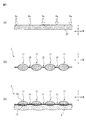
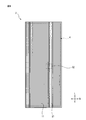
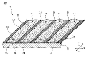
- FIG. 2 is an enlarged cross-sectional view taken along the line II-II ′ of FIG. 1 of the absorbent article according to the embodiment. It is an expanded sectional view showing a manufacturing method of a surface sheet of an absorptive article concerning an embodiment. It is a top view of a surface sheet and an absorber of an absorptive article concerning an embodiment. It is a perspective view of the surface sheet of the absorbent article which concerns on embodiment. It is an expanded sectional view in frame Q1 of Drawing 2 of an absorptive article concerning an embodiment. It is a schematic diagram explaining an example of the relationship between the surface sheet in the frame Q2 of FIG.
- the absorbent article according to the present embodiment will be described with reference to the drawings.
- the type and application of the absorbent article of the present invention are not limited to the examples, and for example, sanitary articles such as disposable diapers (tape type, pants type), sanitary napkins, panty liners, incontinence pads, sweat removing sheets, etc.
- sanitary articles such as disposable diapers (tape type, pants type), sanitary napkins, panty liners, incontinence pads, sweat removing sheets, etc.
- sanitary product which may be a human subject or a non-human animal such as a pet.
- the liquid to be absorbed by the absorbent article of the present invention is not particularly limited, and examples thereof include liquid excrement and body fluid of the wearer.
- a disposable diaper (tape type) is taken as an example, and the absorptive article concerning this embodiment is explained.
- the “skin side” means a side closer to the skin surface of the wearer in the thickness direction of the absorbent article when the wearer of the absorbent article wears the absorbent article.
- the “non-skin side” means a side relatively far from the skin surface of the wearer in the thickness direction of the absorbent article when the wearer of the absorbent article wears the absorbent article.
- FIG. 1 and 2 are views showing an absorbent article 1 (disposable diaper). Specifically, FIG. 1 shows a plan view of the absorbent article 1 in an unfolded state, and FIG. An enlarged sectional view of II ′ is shown.
- the absorbent article 1 has a longitudinal direction L, a width direction W orthogonal to the longitudinal direction L, and a thickness direction T orthogonal to the longitudinal direction L and the width direction W, and is located on the skin side of the wearer.
- a liquid-permeable top sheet 2, a liquid-impermeable back sheet 3 positioned on the non-skin side of the wearer, and an absorbent body 4 positioned between these two sheets are provided.
- the absorber 4 and the surface sheet 2 and the back surface sheet 3 are each joined by the adhesive.
- the longitudinal direction, the width direction, and the thickness direction of the top sheet 2, the back sheet 3, and the absorbent body 4 coincide with the longitudinal direction L, the width direction W, and the thickness direction T of the absorbent article 1, respectively. Therefore, in the top sheet 2, the back sheet 3, and the absorbent body 4, the longitudinal direction L, the width direction W, and the thickness direction T are respectively used with respect to the longitudinal direction, the width direction, and the thickness direction, and are relatively worn in the thickness direction.
- the skin side and the non-skin side are used for the side close to the person's skin and the side far from the person.
- the absorbent article 1 further extends and contracts in the longitudinal direction L each of the pair of leak-proof wall portions 5 and 5 formed of a pair of side sheets and the left and right leg surrounding portions that contact the thigh of the wearer.
- An elastic member 6 made of an elastic material such as rubber and a connecting tape 7 for connecting the abdomen region and the back region of the disposable diaper when worn are provided.
- the absorbent article 1 further includes an exterior sheet 8 on the non-skin side of the back sheet 3 to reinforce the back sheet 3 and improve the touch.
- the exterior sheet 8 is joined to the pair of leak-proof wall portions 5, 5 and the peripheral portion thereof while being joined to the non-skin side of the back sheet 3.
- the expansion-contraction member for expanding / contracting each of a pair of leak-proof wall parts 5 and 5 to the longitudinal direction L may be arrange
- the back sheet 3 is provided on the non-skin side of the absorbent body 4 and prevents the discharged excretory fluid from permeating to prevent leakage into the underwear or clothes.
- the back sheet 3 does not transmit liquid such as excretory liquid, but has predetermined air permeability.
- the back sheet has air permeability, moisture released from the absorber to the non-skin side can be released through the back sheet, and is worn in the absorbent article or with the absorbent article. The moisture staying between the person's skin surface can be reduced.
- the back surface sheet 3 is mutually joined in the state which pinched
- Examples of the material for the back sheet 3 include waterproof nonwoven fabric (for example, point bond nonwoven fabric, spunbond nonwoven fabric, spunlace nonwoven fabric, etc.), synthetic resin (for example, polyethylene, polypropylene, polyethylene terephthalate, etc.) film, nonwoven fabric, and the like.
- Examples include composite sheets with synthetic resin films.
- the material, thickness, basis weight, density, and the like of the back sheet 3 can be appropriately adjusted within a range in which leakage of liquid excretion absorbed and held by the absorber 4 can be prevented.
- the absorber 4 absorbs excretory fluid such as urine, and uses an absorbent material that absorbs and retains excreted fluid. Moreover, this absorber 4 is formed in the substantially rectangular shape long in the longitudinal direction L by planar view, and has fixed thickness. In addition, in another shape, for example, in plan view, both end sides in the longitudinal direction L are curved so as to protrude outward in the longitudinal direction L, and are formed in a substantially oval shape smaller than the top sheet 2 and the back sheet 3. It may be.
- the absorbent body 4 in the present embodiment has a flat shape both on the surface sheet side, that is, on the skin side surface and on the back sheet side, that is, on the non-skin side surface.
- the absorbent body 4 includes a liquid-permeable surface core wrap sheet 401 located on the wearer's skin side, a liquid-permeable or liquid-impermeable back core wrap sheet 402 located on the non-skin side of the wearer, and these It is located between the two sheets and includes an absorbent core 403 formed of an absorbent material.
- the front surface core wrap sheet 401 and the back surface core wrap sheet 402 are bonded to each other at their peripheral portions in a state where the absorbent core 403 is sandwiched between the both sheets, and the absorbent material or the like. Is configured not to leak outward.
- the front core wrap sheet 401 and the back core wrap sheet 402 may be configured to wrap the absorbent core 403 with a single member.
- the absorbent material contained in the absorbent core 403 is not particularly limited as long as it can absorb and retain the liquid excrement of the wearer.
- the absorptive material include water-absorbing fibers and highly water-absorbing materials (for example, highly water-absorbing resins and highly water-absorbing fibers).
- the absorptive material may contain an antiblocking agent, an ultraviolet absorber, a thickening branching agent, a matting agent, a colorant, and other various improving agents.
- water-absorbing fibers include wood pulp obtained from softwood or hardwood (for example, mechanical pulp such as groundwood pulp, refiner ground pulp, thermomechanical pulp, chemithermomechanical pulp; kraft pulp, sulfide pulp, alkaline pulp, etc. Chemical pulp; semi-chemical pulp, etc.]; mercerized pulp or crosslinked pulp obtained by subjecting wood pulp to chemical treatment; non-wood pulp such as bagasse, kenaf, bamboo, hemp, cotton (for example, cotton linter); rayon, fibril Examples include regenerated cellulose such as rayon; semi-synthetic cellulose such as acetate and triacetate, but pulverized pulp is preferred because it is low in cost and easy to mold.
- wood pulp obtained from softwood or hardwood for example, mechanical pulp such as groundwood pulp, refiner ground pulp, thermomechanical pulp, chemithermomechanical pulp; kraft pulp, sulfide pulp, alkaline pulp, etc. Chemical pulp; semi-chemical pulp, etc.]; mercerized pulp or crosslinked pulp obtained by subjecting wood
- the superabsorbent material examples include starch, cellulose, and synthetic polymer superabsorbent materials.
- starch-based or cellulose-based superabsorbent materials include starch-acrylic acid (salt) graft copolymers, saponified starch-acrylonitrile copolymers, and crosslinked products of sodium carboxymethyl cellulose.
- high water-absorbing materials include polyacrylates, polysulfonates, maleic anhydrides, polyacrylamides, polyvinyl alcohols, polyethylene oxides, polyaspartates, polyglutamates , Polyalginate-based, starch-based, and cellulose-based superabsorbent polymers (SAP), and the like.
- polyacrylate-based (particularly, sodium polyacrylate-based) superabsorbent Resins are preferred.
- the shape of the superabsorbent material include particles, fibers, and scales.
- the thickness, basis weight, and the like of the absorbent core 403 are not particularly limited, and may be appropriately adjusted according to characteristics (for example, absorbency, strength, lightness, etc.) that the absorbent body 4 (example: disposable diaper) should have. it can.
- the thickness of the absorber 4 is usually in the range of 0.1 to 15 mm, preferably in the range of 1 to 10 mm
- the basis weight is usually in the range of 20 to 1000 g / m 2 , preferably Is in the range of 50 to 800 g / m 2 .
- the thickness, basis weight, etc. of the absorber core 403 may be constant over the entire absorber 4, or may be partially different. In this Embodiment, it is constant over the absorber 4 whole.
- the materials of the front core wrap sheet 401 and the back core wrap sheet 402 are not particularly limited as long as they have liquid permeability and absorber core retention.
- Examples of the material of both sheets include known materials such as a tissue, a nonwoven fabric of hydrophilic fibers, and a hydrophilic nonwoven fabric made of hydrophilic processed fibers. From the viewpoints of low cost and absorbent retainability, a tissue formed from a pulverized pulp as a main material by a wet method is preferable.
- the thickness, basis weight, fineness, fiber length, and the like of the front core wrap sheet 401 and the back core wrap sheet 402 are not particularly limited as long as they have liquid permeability and can hold the absorbent core 403.
- Absorbent articles A known value can be used.
- the thickness of both sheets is in the range of 0.01 to 2 mm, preferably in the range of 0.05 to 1 mm, and the basis weight is in the range of 5 to 50 g / m 2 , preferably 10 to 30 g / m 2 .
- the fineness is usually 0.5 to 5 dtex, preferably 1.0 to 4.0 dtex, and the fiber length is usually 30 to 60 mm, preferably 35 to 55 mm.
- the thickness, basis weight, fineness, fiber length and the like of both sheets are constant throughout the absorbent body 4. However, the thickness, basis weight, fineness, fiber length, etc. of both sheets may be partially different.
- the top sheet 2 is provided on the skin side of the absorbent body 4, abuts on the skin of the wearer, quickly absorbs or permeates excretion fluid from the wearer, and moves toward the absorbent body 4.
- the topsheet 2 has a concavo-convex structure in which concave portions and convex portions extending in the longitudinal direction L are alternately arranged in the width direction W.
- the surface sheet 2 is long in the direction in alignment with the longitudinal direction L, and is formed in the substantially rectangular shape.
- the material of the top sheet 2 is not particularly limited as long as it has liquid permeability and includes heat-fusible fibers.
- a nonwoven fabric is mentioned, for example.
- the nonwoven fabric can be manufactured, for example, by forming a web (fleece) and bonding the fibers physically and chemically.
- the web forming method include a spunbond method, a dry method (a carding method, an airlaid method), a wet method, and the like.
- Examples of the bonding method between fibers include a thermal bond method (calendar method, air-through method, etc.), a chemical bond method, and a mechanical bond method (needle punch method, hydroentanglement method, stitch bond method, etc.).
- fibers constituting the nonwoven fabric include natural fibers (wool, cotton, etc.), recycled fibers (rayon, acetate, etc.), inorganic fibers (glass fibers, carbon fibers, etc.), synthetic resin fibers (polyethylene, polypropylene, polybutylene, ethylene).
- -Polyolefin such as vinyl acetate copolymer, ethylene-ethyl acrylate copolymer, ethylene-acrylic acid copolymer, ionomer resin
- Polyester such as polyethylene terephthalate, polybutylene terephthalate, polytrimethylene terephthalate, polylactic acid;
- polyamides such as nylon).
- the fiber constituting the nonwoven fabric may be composed of a single component, or may be composed of a composite fiber such as a core / sheath fiber, a side-by-side fiber, or an island / sea fiber.
- a single-layer nonwoven fabric or a laminate in which single-layer nonwoven fabrics are laminated may be used.
- the thickness, basis weight, fineness, fiber length, and the like of the surface sheet 2 are not particularly limited as long as they have liquid permeability, and known values can be used for absorbent articles.
- the thickness of the top sheet 2 is in the range of 0.1 to 5 mm, preferably in the range of 0.2 to 3 mm, and the basis weight is in the range of 5 to 100 g / m 2 , preferably Is 10 to 50 g / m 2 .
- the fineness is usually 0.5 to 10 dtex, preferably 1.0 to 5.0 dtex, and the fiber length is usually 20 to 100 mm, preferably 30 to 70 mm.
- the thickness, basis weight, fineness, fiber length, and the like of the surface sheet 2 are constant over the entire surface sheet 2. However, the thickness, basis weight, fineness, fiber length, etc. of the topsheet 2 may be partially different.
- the absorbent body 4 is bonded to the surface sheet 2 on the skin side surface of the surface core wrap sheet 401 with an adhesive, and the back surface sheet 3 on the non-skin side surface of the back surface core wrap sheet 402. Bonded with adhesive.
- the material for the adhesive is not particularly limited, and examples thereof include a hot melt adhesive.
- the hot melt adhesive can be appropriately selected from known hot melt adhesives such as synthetic rubber, polyolefin, ethylene-vinyl acetate, polyurethane and acrylic.
- the topsheet 2 has a concavo-convex structure in which concave portions and convex portions extending in the longitudinal direction L are alternately arranged in the width direction W.
- the surface sheet 2 which has such an uneven structure is manufactured by embossing.
- FIG. 3 is an enlarged cross-sectional view showing a method for manufacturing such a top sheet 2.
- an unprocessed nonwoven fabric 2P is prepared as a material for the topsheet 2.
- the non-woven fabric 2P is a non-woven fabric mentioned as the material for the top sheet 2 described above.
- the nonwoven fabric 2P is conveyed to an embossing apparatus.
- an embossing roll in which wavy teeth are formed at a predetermined pitch along the width direction on the outer circumferential surface and an anvil roll are arranged facing each other, and between the embossing roll and the anvil roll.
- Nonwoven fabric 2P is sandwiched.
- the pressure Pe is applied to the nonwoven fabric 2P sandwiched between the embossing roll and the anvil roll at a predetermined pitch.
- the places where the pressure Pe is applied extend in the transport direction (MD direction) and are arranged at a predetermined interval in the width direction (CD direction) perpendicular to the transport direction.
- a plurality of concave portions that is, a plurality of fused portions 21 are formed (embossing).
- a plurality of convex parts extending in the transport direction (MD direction) and relatively protruding from the fusion part 21 in the thickness direction T, that is, A plurality of protrusions 11 are formed at predetermined intervals in the width direction (CD direction).
- the fused portion 21 since the non-woven fabric 2P is formed by being compressed and fused, the fused portion 21 has a very thin plate shape and has a structure that hardly expands or contracts.
- the protruding portion 11 since the non-woven fabric 2P is formed without being compressed, the protruding portion 11 has an elliptical column shape having an elliptical cross section having a minor axis substantially the same as the thickness of the non-woven fabric 2P, and in the width direction (CD direction).
- the structure can be expanded and contracted and has flexibility in the thickness direction.
- the embossing roll may apply pressure Pe while heating the nonwoven fabric 2P.
- the topsheet 2 having a concavo-convex structure can be formed easily and at low cost. That is, it can be said that the embossing method is one of the preferred forms as a method for forming the topsheet 2 having an uneven structure.
- the surface sheet 2 formed in this way is then joined to the absorber 4 via an adhesive.
- the surface sheet 2 is joined while being strongly pressed against the absorber 4, so that the surface of the surface sheet 2 on the side of the absorber 4 is not only the protruding portion 11 but also the fused portion 21. 4 sticks.
- the portion 15 of the protrusion 11 on the absorber 4 side is crushed and the degree of protrusion is reduced, and the portion 13 of the protrusion 11 opposite to the absorber 4 is crushed. Instead, the degree of protrusion increases. At this time, the tensile strength of the surface sheet is also improved.
- FIG. 4 is a plan view showing a state in which the top sheet 2 and the absorber 4 are overlapped.
- the topsheet 2 has the longitudinal direction as the direction in which the fused portion 21 and the protrusion 11 of the topsheet 2 extend, that is, the transport direction during manufacture.
- the surface sheet 2 and the absorber 4 are joined so that the longitudinal direction of the surface sheet 2 and the longitudinal direction of the absorber 4 may become mutually parallel.
- the protrusion part 11 is extended beyond both the edges in the longitudinal direction L of the absorber 4, this invention is not limited to such a form,
- the protrusion part 11 May extend to at least one end edge in the longitudinal direction L of the absorbent body 4 or beyond one end edge. If the protrusion part 11 is extended in this way, the air permeability of the surface sheet 2 can be further improved.
- FIGS. 5 to 6 are views showing the configuration of the top sheet 2
- FIG. 5 is a perspective view of the top sheet 2
- FIG. 6 is an enlarged sectional view in the frame Q1 of FIG.
- the top sheet 2 includes a first surface 2 a located on the side opposite to the absorber 4, and a second side located on the side opposite to the first surface 2 a, that is, on the absorber 4 side.
- Surface 2b The plurality of fused portions 21 of the top sheet 2 extend in the longitudinal direction L and are arranged in parallel with each other at a predetermined interval in the width direction W.
- the plurality of protrusions 11 extend in the longitudinal direction L between adjacent fusion parts 21 among the plurality of fusion parts 21, and the first surface 2 a side of the fusion part 21 in the thickness direction T and the first. It protrudes to the 2nd surface 2b side, ie, the skin side and the non-skin side.
- the surface sheet 2 and the surface core wrap sheet 401 of the absorbent body 4 are intimately bonded via an adhesive 9.
- the adhesive 9 is arranged in a predetermined pattern which will be described later. Therefore, even in a portion without the adhesive 9, there is almost no gap between the top sheet 2 and the top core wrap sheet 401.
- the adhesive 9 is present below the protrusion 11, it is possible to make the protrusion 11 less likely to expand and contract in the width direction W than the adhesive 9. Thereby, the expansion
- fusion part 21 by the side of the 1st surface 2a The difference, that is, the height of the top portion 12 with respect to the bottom portion 22 is Tu, and the difference between the top portion 14 of the protruding portion 11 on the second surface 2b side and the bottom portion 24 of the fusion portion 21 on the second surface 2b side, that is, The height of the top 14 with respect to the bottom 24 is defined as Td.
- Tu Td.
- the protrusion 11 on the second surface 2b side has a shape that is more crushed than the protrusion 11 on the first surface 2a side. That is, the unevenness of the surface sheet 2 on the second surface 2b side (surface core wrap sheet 401 side) is reduced. Therefore, the adhesive 9 can be easily disposed also in the fusion part 21 which is a concave portion on the second surface 2b side of the top sheet 2, and the adhesive 9 is more reliably bound to the top sheet 2 on the top core wrap sheet 401 side. it can. Thereby, the expansion
- the part 15 by the side of the absorber 4 (surface core wrap sheet 401) of the protrusion part 11 is crushed, ie, the extent of protrusion is low and a fiber density becomes high.
- the portion 13 on the opposite side to the absorbent body 4 (surface core wrap sheet 401) side of the protrusion 11 is not crushed, that is, the degree of protrusion is high and the fiber density is low. Therefore, in the portion 15 on the surface core wrap sheet 401 side, the adhesive 9 can penetrate very well into the high fiber density portion 15 due to the high fiber density. Thereby, the adhesive 9 can be very well bound to the high fiber density portion 15, and the protrusion 11 can be made difficult to expand and contract in the width direction W. Thereby, the expansion
- the surface sheet 2 is formed using the nonwoven fabric (example: air through nonwoven fabric, point bond nonwoven fabric, spun pond nonwoven fabric, or SMS nonwoven fabric) which couple
- nonwoven fabrics at least a part of the intersections of the fibers are fused to each other in order to bond the fibers constituting the nonwoven fabric by heat. Therefore, it is possible to make the surface sheet 2 difficult to extend as compared to the surface sheet 2 using a non-fused nonwoven fabric at the intersection of the fibers constituting the nonwoven fabric.
- the density of the intersection where the fibers are fused also increases. Thereby, the expansion
- the width Wn of the protrusion 11 is preferably 1 to 5 mm, more preferably 1.5 to 4 mm, and still more preferably 2 to 3 mm. If the width Wn of the protruding portion 11 is less than 1 mm, the uneven structure of the topsheet 2 is too fine, and the contact area between the protruding portion 11 and the skin of the wearer cannot be reduced so much. The touch may be reduced. On the other hand, when the width Wn of the protruding portion 11 exceeds 5 mm, the structural difference from the nonwoven fabric before the uneven shaping process decreases, and thus the characteristics of the absorbent article 1 including the topsheet 2 having the uneven structure are exhibited. It becomes difficult to do.
- the interval between the adjacent protruding portions 11, that is, the width Wm of the fused portion 21 is preferably 0.3 to 2 mm, more preferably 0.5 to 1.mm. 5 mm, more preferably 0.7 to 1 mm.
- the distance between the adjacent protrusions 11 is less than 0.3 mm, the uneven structure of the topsheet 2 is too fine, and the contact area between the protrusions 11 and the skin of the wearer cannot be reduced so much. There is a possibility that the touch of the top sheet 2 is lowered.
- the distance between the adjacent protrusions 11 exceeds 5 mm, the structural difference from the non-woven fabric before the uneven shaping process is reduced. Therefore, the absorbent article provided with the topsheet 2 having the uneven structure It becomes difficult to express the characteristic of 1.
- the size of one pitch PI which is the sum of the width Wm of one fused portion 21 and the width Wn of one protruding portion 11, is 1.3 to 7 mm. Preferably, it is 2 to 5.5 mm, more preferably 2.7 to 4 mm.
- the width Wn of the protruding portion 11 is preferably larger than the width Wm of the fused portion 21 in the width direction W. Since the width Wn of the protruding portion 11 is large, the height Tu in the thickness direction T of the protruding portion 11 can be further increased, whereby the absorptivity provided with the topsheet 2 in which concave portions and convex portions are alternately arranged. The characteristics of the article 1 can be exhibited more.
- the height Tu on the first surface side of the protrusion 11 is preferably 0.2 to 5 mm, more preferably 0.4 to 4 mm, and still more preferably. Is 0.6 to 3 mm. If the height of the protrusion 11 is less than 0.25 mm, the protrusion of the protrusion 11 is too small, and the structural difference from the nonwoven fabric before the uneven shaping process is reduced. It becomes difficult to express the characteristics of the absorbent article 1 with 2. On the other hand, when the height of the protrusion 11 exceeds 5 mm, the protrusion of the protrusion 11 is too large and has a sharp structure, so that it is difficult to obtain a soft touch.
- the thickness Tm of the fused portion 21 is preferably 0.05 to 2 mm, more preferably 0.1 to 1.5 mm, and more preferably 0.00. 2 to 1 mm. If the thickness of the fused part 21 is less than 0.05 mm, the fiber density of the fused part 21 becomes very high, the fused part 21 becomes too hard, and the wearer may feel uncomfortable. On the other hand, when the thickness of the fused part 21 exceeds 2 mm, the depression of the fused part 21 is too small, and the structural difference from the nonwoven fabric before the irregular shape forming process is reduced. It becomes difficult to express the characteristic of the absorbent article 1 provided with.
- the topsheet 2 has a concavo-convex structure, that is, the fusion part 21 and the protrusion part 11 that extend continuously in the longitudinal direction L.
- the characteristic (action effect) of the absorptive article 1 provided with the surface sheet 2 which has an uneven structure can be produced. That is, the excrement hardly adheres to the skin when the excrement enters the recess (fused part 21). Absorption of excrement is promoted by increasing the surface area of the topsheet 2 due to the concavo-convex structure (the fused portion 21 and the protruding portion 11).
- the entire absorbent body 4 can be used for the excretion absorption without waste.
- the air permeability is improved along the longitudinal direction L by the concave portion (fused portion 21).
- a contact area with a wearer's skin falls by a recessed part (fusion part 21).
- a soft touch utilizing the concavo-convex structure is obtained by the flexibility of the convex portion (protruding portion 11).
- the fused portion 21 and the protruding portion 11 are linearly extended, i.e., have a grooved structure extending in the longitudinal direction L. It can play very remarkably.
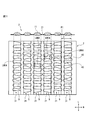
- FIG. 7 is a schematic diagram for explaining an example of the relationship between the topsheet 2 and the predetermined pattern of the adhesive 9 in the frame Q2 of FIG.
- FIG. 7A is a schematic diagram showing the relationship between the protruding portion 11 and the fused portion 21 of the topsheet 2 and the predetermined pattern 30 when the adhesive 9 is applied.
- FIG. 7B is an enlarged view showing the predetermined pattern 30 of the adhesive 9.
- the adhesive 9 has a thin line shape.
- the wire diameter of the adhesive 9 is preferably 10 to 500 ⁇ m, more preferably 50 to 300 ⁇ m. If the wire diameter of the adhesive 9 is smaller than 10 ⁇ m, the adhesive 9 is interrupted during coating, and it becomes difficult to form the predetermined pattern 30. On the other hand, if the wire diameter of the adhesive 9 is larger than 500 ⁇ m, the adhesive 9 is too thick and obstructs the absorption of excrement, and the absorption performance may be lowered.
- a hot melt adhesive can be used as a material of the adhesive 9, for example.
- the adhesive 9 in the shape of a thin line forms a predetermined pattern 30.
- an omega pattern similar to the Greek letter ⁇ is used as the predetermined pattern 30.
- the fine-line adhesive 9 can be evenly disposed between the top sheet 2 and the top core wrap sheet 401.
- the predetermined pattern 30 has at least a horizontal portion 32a and a vertical portion 33a.
- the lateral portion 32a is a lateral portion 32a that extends along the width direction W and connects at least one fusion part 21 and the protrusion 11 adjacent to the at least one fusion part 21, and has a predetermined pattern.
- the longitudinal portion 33a is a longitudinal portion 33a that extends along the longitudinal direction L and has one end connected to one end of the lateral portion 32a, and at any point on the thin line of the adhesive 9 that forms the predetermined pattern 30.
- one end of the horizontal portion 32a is E2
- the other end is E1
- one end of the vertical portion 33a is E2
- the other end is E3.
- the predetermined pattern 30 further includes a horizontal portion 32b and a vertical portion 33b.
- the lateral portion 32b extends in the width direction W, and is a lateral portion 32b that connects at least one fusion part 21 and the protrusion 11 adjacent to the at least one fusion part 21, and has a predetermined pattern.
- the vertical portion 33b is a vertical portion 33b extending along the longitudinal direction L and having one end connected to one end of the horizontal portion 32b, and at any point of the fine line of the adhesive 9 forming the predetermined pattern 30.
- one end of the lateral portion 32b is E4 and the other end is E3.
- the horizontal portion 32b has the other end E3 connected to the other end E3 of the vertical portion 33a.
- One end of the vertical portion 33b is E4, the other end is another E1, and the vertical portion 33b is connected to the other end of the horizontal portion 32a of the next predetermined pattern 30 at the other end E1.
- a plurality of the predetermined patterns 30 in FIG. 7B are arranged along the longitudinal direction L, and a predetermined pattern row 31 extending continuously along the longitudinal direction L is formed. is doing. As further shown in FIG. 7A, the predetermined pattern rows 31 are arranged in parallel with each other in a plurality of rows in the width direction W.
- the protrusions 11 that overlap the predetermined pattern row 31, that is, the region 40 in one protrusion 11 separated by the lateral portion 32 adjacent in the longitudinal direction L that is, the region 40 in one protrusion 11 separated by the lateral portion 32 adjacent in the longitudinal direction L.
- the horizontal portion 32 is adjacent to the longitudinal direction L
- the horizontal portion 32a and the horizontal portion 32b in the same predetermined pattern 30 may be used, or the horizontal portions 32a of the different predetermined patterns 30 may be used.
- the lateral portion 32b That is, for each predetermined pattern row 31, one protruding portion 11 is partitioned by a plurality of lateral portions 32 (not limited to the lateral portion 32 in the same predetermined pattern 30) arranged in the longitudinal direction L.
- a plurality of regions 40 aligned in the longitudinal direction L are defined in the one protrusion 11.
- the minimum distance LMIN among the distances in the longitudinal direction L between the lateral portions 32 adjacent to each other in the longitudinal direction L is the distance between the protruding portion 11 and the fusion portion 21.
- the minimum distance LMIN in the longitudinal direction between the lateral portions 32 of the adhesive 9 adjacent to each other in the longitudinal direction L is thus the width in the width direction W of one set of the protruding portion 11 and the fusion portion 21 ( It is narrower than (distance). Therefore, for the reason described later, the topsheet 2 does not extend excessively even in an intermediate region between the lateral portions 32, and the extension of the protruding portion 11 can be sufficiently suppressed. That is, the expansion of the topsheet 2 can be sufficiently suppressed, so that even if the topsheet 2 is pulled in the width direction W, the topsheet 2 does not extend so much in the width direction W. Since the surface core wrap sheet 401 is hardly stretched, the surface core wrap sheet 401 can be prevented from breaking.
- the elasticity of the topsheet 2 is sacrificed to some extent. Can be suppressed. Thereby, even when a tensile load is applied in the width direction W, the degree of elongation is suppressed, and the characteristics of the absorbent article 1 including the topsheet 2 having an uneven structure can be maintained.
- the breakage reaches the lateral portions 32 on both sides if the distance between the lateral portions 32 is large. It becomes too large until it becomes difficult to stop the elongation of breakage with the thin-line adhesive 9.
- the interval between the lateral portions 32 is narrow, the fracture does not become too large until the lateral portions 32 on both sides are reached, and even the fine-line adhesive 9 stops the elongation of the fracture. be able to.
- the rupture can be suppressed to an extremely narrow range, so that the rupture of the entire surface core wrap sheet 401 can be suppressed.
- the size of the predetermined pattern 30 (FIG. 7B) in the width direction W is equal to one fusion part 21 and one fusion point. If it has the magnitude
- the size of the predetermined pattern 30 in the width direction W is equal to or greater than the sum of the width Wm in the width direction W of one fused portion 21 and the width Wn in the width direction W of one protrusion 11. It is preferable. This is because it is possible to more reliably form the lateral portion 32 that can connect one fused portion 21 and the protruding portion 11 adjacent to the one fused portion 21.
- the size of the predetermined pattern 30 (FIG. 7B) in the longitudinal direction L is the horizontal width adjacent to the longitudinal direction L in the predetermined pattern row 31.
- the minimum distance in the longitudinal direction L between the direction portions 32 is less than the width in the width direction W of one set of the protruding portion 11 and the fusion portion 21.
- the size of the predetermined pattern 30 in the longitudinal direction L is such that the maximum distance in the longitudinal direction L between the lateral portions 32 adjacent to each other in the longitudinal direction L corresponds to a set of the protruding portion 11 and the fusion portion 21. It is less than the width in the width direction W.
- the minimum distance in the longitudinal direction L between the lateral portions 32 adjacent to each other in the longitudinal direction L is set to be less than the width (Wm + Wn) in the width direction W of one set of the protruding portion 11 and the fusion portion 21. The reason will be described below.
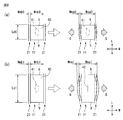
- FIG. 8 is a schematic diagram for explaining a mechanism that causes the absorbent article to break.
- a virtual region 40 on the top sheet 2 is considered as shown in the left diagram of FIG.
- the region 40 is formed by the fusion part 21 (width Wmb0) disposed on both sides of the protrusion part 11 in the width direction W and the two adhesives 9 crossing the protrusion part 11 in the width direction W. It is defined within (width Wnb0).
- the two adhesives 9 are separated in the longitudinal direction L by the interval Lp0. In this case, the two adhesives 9 can be viewed as a lateral portion of the predetermined pattern 30.
- the region 40 is a region surrounded by the fused portions 21 on the both sides of the protruding portion 11 and the two adhesives 9.
- the adhesive 9 does not stretch tightly. Therefore, as shown in the right view of FIG. A region where the adhesive 9 is present and a region in the vicinity thereof (a lateral portion and a region in the vicinity thereof) hardly extend in the width direction W.
- the fused portion 21 has almost no elasticity, but can be bent a little. Therefore, the width of the region away from the adhesive 9 in the fused portion 21 is almost unchanged (Wma0 ⁇ Wmb0) and slightly curved in the width direction W.
- the region of the protruding portion 11 away from the adhesive 9 extends to some extent in the width direction W. That is, the width of the protrusion 11 is slightly increased (Wnb0 ⁇ Wna0).
- the distance Lp0 in the longitudinal direction L of the two adhesives 9 is sufficiently small, the fused portion 21 cannot be bent so much by the influence of the two adhesives 9, that is, the protruding portion 11 is in the width direction W. It is hardly stretched. That is, the width of the protrusion 11 is not so large.
- the two adhesives 9 are spaced apart in the longitudinal direction L by a distance Lp1 (> Lp0). That is, compared with the area
- FIG. 9 is a schematic diagram showing the relationship of forces in the region 40. As shown in FIG. 9 ,
- the threshold value (the maximum value of the interval Lp) is a value that makes the region 40 square, that is, the width Wn of the protruding portion 11.
- the threshold value (maximum value of the interval Lp) in consideration of the width Wm of the fused portion 21 was examined as follows.
- FIG. 10 is a schematic diagram showing the relationship between the distance between the adhesives 9 in the longitudinal direction L in the region 40 and the width Wm of the fused portion 21. 10A, the area 40 is square in FIG. 8A, and the width Wm of the fused portion 21 is set to a small value (example: about the thickness of the adhesive 9) Wmb3.
- the region 40 can be regarded as a substantially square. That is, the protrusion 11 is not greatly extended in the width direction W.
- the width Wmb4 when considering the width Wmb4 >> width Wmb3, the width Wm of the fused portion 21 is increased by Wmb4 as compared with the case of FIG. 10A, and the extent to which the fused portion 21 is curved correspondingly. Suppressed. Therefore, the distance Lp4 between the two adhesives 9 in the longitudinal direction L can be made somewhat larger ( ⁇ L1) than the value that makes the region 40 square.
- the width Wm of the fused portion 21 is increased by Wmb5 compared to the case of FIG. 10A, and the extent to which the fused portion 21 is curved correspondingly. Suppressed. Accordingly, the distance Lp5 between the two adhesives 9 in the longitudinal direction L can be made somewhat larger ( ⁇ L2) than the value that makes the region 40 square.
- the effect given to the distance Lp in the longitudinal direction L of the two adhesives 9 may be at most approximately the distance corresponding to the width Wm of the fused portion 21. Conceivable. That is, it is considered that ⁇ L1 and ⁇ L2 are at most approximately the widths Wmb4 and Wmb5 of the fused portion 21 at the maximum.
- Lp4 Wnb4 + Wmb4
- Lp5 Wnb5 + Wmb5 It becomes.
- the threshold value is derived based on a virtual shape region 40 as shown in FIG.
- the predetermined pattern row 31 has a configuration in which the predetermined patterns 30 are continuously arranged along the longitudinal direction L, that is, a configuration in which the predetermined patterns 30 are connected to each other and extended (however, it may be partially interrupted by a manufacturing yield or the like). ing.
- At least a part of the interval in the longitudinal direction L between the lateral portions 32 adjacent to each other in the longitudinal direction L is the above-mentioned. If the threshold value is satisfied, it is considered effective in suppressing the extension of the protrusion 11. That is, it is understood that at least the minimum distance in the longitudinal direction L between the lateral portions 32 only needs to satisfy the above threshold. Therefore, in order to suppress the extension of the protruding portion 11, at least the minimum distance of the distance in the longitudinal direction L between the lateral portions 32 adjacent to each other in the longitudinal direction L is set to be equal to one set of the protruding portion 11 and the fusion portion 21.
- the maximum distance in the longitudinal direction L between the lateral portions 32 adjacent to each other in the longitudinal direction L is less than the width (Wm + Wn) in the width direction W of one set of the protruding portion 11 and the fusion portion 21. To do.
- the extension of the protruding portion 11 can be sufficiently suppressed. That is, extension of the top sheet 2 can be sufficiently suppressed. Thereby, even if the surface sheet 2 is pulled in the width direction W, the surface sheet 2 does not extend so much in the width direction W, that is, the surface core wrap sheet 401 hardly expands. Can be suppressed.
- the threshold value is not limited to the virtual region 40 as shown in FIG. 8A or the omega pattern as shown in FIG.
- the present invention can be similarly applied to a pattern, for example, a wave pattern having a waveform like a sine wave or a spiral pattern having a spiral shape.
- the adhesive 9 does not necessarily have to be bridged between the adjacent protruding portions 11.
- At least a pair of the protruding portion 11 and the fusion portion 21 has a minimum distance in the longitudinal direction L between the lateral portions 32 adjacent to each other in the longitudinal direction L. It can be seen that by narrowing to less than the width (Wm + Wn) in the width direction W of the minute, it is possible to achieve both the characteristics of the absorbent article provided with the topsheet having the concavo-convex structure and the suppression of the breakage of the top corewrap sheet. .
- FIG. 11 is a schematic diagram for explaining another example of the relationship between the topsheet 2 and the predetermined pattern 30 of the adhesive 9 in the frame Q2 of FIG.
- FIG. 11 schematically shows the relationship between the protruding portion 11 and the fused portion 21 of the topsheet 2 and the predetermined pattern 30 when the adhesive 9 is applied.
- an omega pattern or a wave pattern is used as the predetermined pattern 30.
- the fine-line adhesive 9 can be evenly disposed between the top sheet 2 and the top core wrap sheet 401.
- extension in the width direction W of the surface sheet 2 can be suppressed uniformly,
- rupture of the surface core wrap sheet 401 can be suppressed more reliably.
- each predetermined pattern 30 in the width direction W, the vertical portion of each predetermined pattern 30 reaches at least the fused portions 21 on both sides, and the horizontal portion (and the vertical portion) is at least the protruding portion 11. Crossing from one side to the other.
- the predetermined pattern 30 has the adhesive 9 bridged between the fusion portions 21 on both sides of the one protruding portion 11.
- the present invention is not limited to this example, and the adhesive 9 is bridged between the fusion parts 21 on both sides of the plurality of protrusions 11 and the plurality of fusion parts 21 therebetween. May be passed. In that case, the extension of the protrusion 11 can be more stably suppressed.
- FIG. 12 is a schematic diagram for explaining another example of the relationship between the topsheet 2 and the predetermined pattern 30 of the adhesive 9 in the frame Q2 of FIG.
- FIG. 12A is a schematic diagram showing the relationship between the protruding portion 11 and the fused portion 21 of the topsheet 2 and the predetermined pattern 30 when the adhesive 9 is applied.
- FIG. 12B is an enlarged view showing a predetermined pattern 30 of the adhesive 9.
- a spiral pattern is used as the predetermined pattern 30. It is.
- the fine-line adhesive 9 can be evenly disposed between the top sheet 2 and the top core wrap sheet 401.
- extension in the width direction W of the surface sheet 2 can be suppressed uniformly, Thereby, the fracture
- a plurality of closed regions surrounded by the adhesive 9 of one or a plurality of predetermined patterns 30 are formed.
- the region in which the protruding portion 11 extends can remain in a narrow region called a closed region with respect to the expansion in the width direction W.
- the extension of the protrusion 11 is limited, the extension of the protrusion 11 in the width direction W can be more reliably suppressed.
- extension of the protrusion part 11 can be confined in the closed area
- the plurality of predetermined pattern rows 31 shown in FIG. 12 are arranged in parallel to each other in the width direction W so as to overlap each other.
- a plurality of predetermined pattern rows 31 overlap with each other. Therefore, the density of the adhesive 9 is increased in the protrusions 11, so that the protrusions 11 are more reliably extended in the width direction W. Can be suppressed.
- a plurality of closed regions can be formed by overlapping the predetermined pattern rows 31 with each other.
- the predetermined patterns 30 shown in FIG. 12B are arranged along the longitudinal direction L so as to overlap each other.
- the predetermined patterns 30 overlap each other, so that the density at which the adhesive 9 is present in the protruding portion 11 is increased, and a plurality of closed regions can be formed.
- FIG. 13 is a schematic diagram for explaining a comparative example of the relationship between the surface sheet of the absorbent article and the adhesive pattern.
- FIG. 13 schematically shows the relationship between the protrusion 111 and the fusion part 121 and the predetermined pattern 130 when the adhesive 109 is applied to the surface sheet 102 having the same uneven structure as the surface sheet 2.
- the protruding portion 111 that overlaps the predetermined pattern row 131 most of the plurality of regions 140 have a minimum distance LMINc among the distances in the longitudinal direction L between the lateral portions adjacent to each other in the longitudinal direction L.
- the distance in the width direction W of one set of the protruding portion 111 and the fused portion 121 specifically, for example, about 1.6 times or more.
Landscapes
- Health & Medical Sciences (AREA)
- Epidemiology (AREA)
- Engineering & Computer Science (AREA)
- Biomedical Technology (AREA)
- Heart & Thoracic Surgery (AREA)
- Vascular Medicine (AREA)
- Life Sciences & Earth Sciences (AREA)
- Animal Behavior & Ethology (AREA)
- General Health & Medical Sciences (AREA)
- Public Health (AREA)
- Veterinary Medicine (AREA)
- Absorbent Articles And Supports Therefor (AREA)
Abstract
Description
(1)表面シートと、裏面シートと、前記表面シートと前記裏面シートとの間に配置された吸収体と、を具備し、前記吸収体が、吸収体コアと前記吸収体コアを包むコアラップシートとを備え、前記表面シートと前記コアラップシートの前記表面シート側の面とを接合する接着剤を更に具備する、吸収性物品であって、前記表面シートは、長手方向と、前記長手方向に直交する幅方向と、前記長手方向及び前記幅方向に直交する厚み方向とを有し、前記長手方向に延び、前記幅方向に所定の間隔で互いに平行に並んだ複数の融着部と、前記複数の融着部のうちの隣り合う融着部の間において、前記長手方向に延び、前記厚み方向における前記融着部の肌側及び非肌側に突出した複数の突出部と、を備え、前記接着剤は、細線の形状を有し、所定パターンを形成しており、前記所定パターンは、前記幅方向に沿って延び、少なくとも一つの融着部と、前記少なくとも一つの融着部に隣接する突出部とを接続する横方向部分であって、前記所定パターンを形成する接着剤の細線の任意の点における接線が前記幅方向に平行な仮想線に対して成す角が45°以内である横方向部分と、前記長手方向に沿って延び、一端を前記横方向部分の一端に連結される縦方向部分であって、前記所定パターンを形成する接着剤の細線の任意の点における接線が前記幅方向に平行な仮想線に対して成す角が45°より大きい縦方向部分と、をそれぞれ少なくとも一つ含み、前記所定パターンは、複数個、前記長手方向に沿って並び、前記長手方向に沿って連続的に延びる所定パターン列を形成しており、前記所定パターン列は、複数列、前記幅方向に互いに平行に並んでおり、前記所定パターン列と重なる前記突出部において、前記長手方向に隣り合う前記横方向部分同士間の長手方向の距離のうち最小の距離は、前記突出部及び前記融着部の一組分の前記幅方向の距離未満である、吸収性物品。
ただし、長手方向に隣り合う横方向部分同士の間隔が広過ぎると、横方向部分の近傍の領域では突出部が伸長することを抑えられるが、各横方向部分から遠い、例えば長手方向における横方向部分同士の中間の領域では突出部が幅方向に伸長し過ぎることがあり得る。その場合、突出部の幅方向への伸長により、隣接する所定パターン列における接着剤の縦方向部分が幅方向に引っ張られ移動し、その縦方向部分の移動にコアラップシートが引き摺られ、幅方向に引っ張られて、破断するおそれがある。すなわち、長手方向に隣り合う横方向部分同士の間隔が広過ぎると、突出部の伸長を十分に抑えられないおそれがある。
そこで、本吸収性物品では、接着剤の所定パターン列における長手方向に隣り合う横方向部分同士の長手方向の最小の距離を突出部及び融着部の一組分の幅方向の幅未満に狭くしている。このように横方向部分同士の間隔を狭くすることにより、横方向部分同士の中間の領域であっても表面シートが伸長し過ぎることはなく、突出部の伸長を十分に抑えることができ、それにより表面シートの伸長を十分に抑えることができる。その結果、表面シートが幅方向に引っ張られても、表面シートが幅方向にあまり伸長せず、すなわちコアラップシートもほとんど伸長されないためコアラップシートが破断することを抑制することができる。
また、本吸収性物品では、上記の接着剤の所定パターン(列)により、伸縮性をある程度犠牲にしているが、その分、伸長に伴い突出部が潰れて薄くなるという事態を抑制できるので、幅方向に引張荷重がかかったときでも、伸長の程度が抑制され、凹部と凸部とが交互に並んだ表面シートを備えた吸収性物品の特性を維持することができる。
本吸収性物品では、更に、横方向部分同士の長手方向の最大の距離を突出部及び融着部の一組分の幅方向の幅未満に狭くしている。このように横方向部分同士の間隔を狭くすることにより、横方向部分同士の中間の領域の伸長、延いては突出部の伸長をより確実に抑えることができる。それにより表面シートの伸長を十分に抑えることができ、コアラップシートが破断することを抑制することができる。
ただし、長手方向における横方向部分同士の中間の領域でコアラップシートが部分的に破断した場合、横方向部分同士の距離が大きいと、破断が両側の横方向部分に達するまでに大きくなり過ぎて、細線状の接着剤では破断の伸展を止めることは困難になるおそれがある。
しかし、本吸収性物品では、上記のように横方向部分同士の間隔が狭くなっているので、破断が大きくなり過ぎる前に両側の横方向部分に達するので、細線状の接着剤でも破断の伸展を止めることができる。それにより、仮にコアラップシートの一部に破断が発生したとしても、破断を極めて狭い範囲に抑えることができるので、全体としての破断を抑制することができる。
本吸収性物品では、コアラップシート側の突出部の繊維密度が高いことにより、接着剤は、コアラップシート側の突出部に深く浸透し、コアラップシート側の突出部と非常に良く結着した状態で、コアラップシートと結着することができる。それにより、突出部の幅方向での伸長を接着剤でより確実に抑制することができ、それによりコアラップシートの破断をより確実に抑制することができる。
本吸収性物品では、繊維同士の交点において繊維同士が融着しているので、接着剤に加えて繊維同士の融着により、突出部の幅方向での伸長をより確実に抑制することができ、それによりコアラップシートの破断をより確実に抑制することができる。
本吸収性物品では、突出部の幅方向の幅が大きいため、突出部の厚み方向の高さを高くすることができ、それにより凹部と凸部とが交互に並んだ表面シートを備えた吸収性物品の特性をより発揮することができる。したがって、表面シートを備えた吸収性物品の特性をより生かしつつ、表面シートの伸長を抑えて、コアラップシートの破断を抑制することができる。
本吸収性物品では、突出部において、コアラップシート側の厚み方向の高さが低いことにより、コアラップシート側の表面シートの凹凸が小さくなるため、コアラップシート側の表面シートに接着剤がより確実に結着できる。その結果、表面シートの伸長をより確実に抑制することができ、それによりコアラップシートの破断をより確実に抑制することができる。
本吸収性物品では、突出部において、コアラップシート側における繊維同士が融着している交点の密度が高い、すなわち繊維同士の相対的な移動がし難いことにより、突出部の伸長を抑制することができる。それにより、コアラップシートの破断をより確実に抑制することができる。
本吸収性物品では、幅方向の伸長に対して、突出部の伸長する領域を閉領域という狭い領域内に留まらせることができる。その結果、突出部の伸長が制限されるので、突出部の幅方向での伸長をより確実に抑制することができる。また、突出部の伸長によるコアラップシートを破断させる力の及ぶ範囲を、その閉領域に閉じ込めることができる。すなわち、突出部に破断が発生したとしても閉領域内に留まらせることができる。それによりコアラップシートの破断をより確実に抑制することができる。
本吸収性物品では、所定パターン列が互いに重なることで、突出部において、接着剤の存在する密度が高まるため、突出部の幅方向での伸長をより確実に抑制することができる。加えて、所定パターン列が互いに重なることで、複数の閉領域を形成することができる。それにより、突出部の伸長する領域を閉領域内に留まらせることができる。これらにより、表面シートの伸長が制限されるので、コアラップシートの破断をより確実に抑制することができる。
本吸収性物品では、所定パターンが互いに重なることで、突出部において、接着剤の存在する密度が高まるため、突出部の幅方向での伸長をより確実に抑制することができる。加えて、所定パターンが互いに重なることで、複数の閉領域を形成することができる。それにより、突出部の伸長する領域を閉領域内に留まらせることができる。これらにより、表面シートの伸長が制限されるので、コアラップシートの破断をより確実に抑制することができる。
本吸収性物品では、所定パターン列がオメガパターン、ウェイブパターン又はスパイラルパターンを有することで、細線状の接着剤を表面シートとコアラップシートとの間に満遍なく配置することができる。それにより、表面シートの幅方向での伸長を満遍無く抑制することができ、それにより、表面コアラップシートの破断をより確実に抑制することができる。
図7は図4の枠Q2内における表面シート2と接着剤9の所定パターンとの関係の一例を説明する模式図である。ただし、図7(a)は、表面シート2の突出部11及び融着部21と接着剤9を塗工するときの所定パターン30との関係を示す模式図である。図7(b)は、接着剤9の所定パターン30を示す拡大図である。
閾値:(二本の接着剤9の長手方向Lの間隔Lpの最大値)
=(突出部11の幅Wn)+ΔL、
=(突出部11の幅Wn)+(融着部21の幅Wm)
である。図10の例では、
(a)Lp4=Wnb4+Wmb4
(b)Lp5=Wnb5+Wmb5
となる。
2 表面シート
3 裏面シート
4 吸収体
9 接着剤
11 突出部
21 融着部
30 所定パターン
31 所定パターン列
32 横方向部分
401 表面コアラップシート
402 裏面コアラップシート
403 吸収体コア
Claims (11)
- 表面シートと、裏面シートと、前記表面シートと前記裏面シートとの間に配置された吸収体と、を具備し、前記吸収体が、吸収体コアと前記吸収体コアを包むコアラップシートとを備え、前記表面シートと前記コアラップシートの前記表面シート側の面とを接合する接着剤を更に具備する、吸収性物品であって、
前記表面シートは、
長手方向と、前記長手方向に直交する幅方向と、前記長手方向及び前記幅方向に直交する厚み方向とを有し、
前記長手方向に延び、前記幅方向に所定の間隔で互いに平行に並んだ複数の融着部と、
前記複数の融着部のうちの隣り合う融着部の間において、前記長手方向に延び、前記厚み方向における前記融着部の肌側及び非肌側に突出した複数の突出部と、を備え、
前記接着剤は、細線の形状を有し、所定パターンを形成しており、
前記所定パターンは、
前記幅方向に沿って延び、少なくとも一つの融着部と、前記少なくとも一つの融着部に隣接する突出部とを接続する横方向部分であって、前記所定パターンを形成する接着剤の細線の任意の点における接線が前記幅方向に平行な仮想線に対して成す角が45°以内である横方向部分と、
前記長手方向に沿って延び、一端を前記横方向部分の一端に連結される縦方向部分であって、前記所定パターンを形成する接着剤の細線の任意の点における接線が前記幅方向に平行な仮想線に対して成す角が45°より大きい縦方向部分と、をそれぞれ少なくとも一つ含み、
前記所定パターンは、複数個、前記長手方向に沿って並び、前記長手方向に沿って連続的に延びる所定パターン列を形成しており、
前記所定パターン列は、複数列、前記幅方向に互いに平行に並んでおり、
前記所定パターン列と重なる前記突出部において、前記長手方向に隣り合う前記横方向部分同士間の長手方向の距離のうち最小の距離は、前記突出部及び前記融着部の一組分の前記幅方向の距離未満である、
吸収性物品。 - 前記所定パターン列と重なる前記突出部において、前記長手方向に隣り合う前記横方向部分同士間の長手方向の距離のうち最大の距離は、前記突出部及び前記融着部の一組分の前記幅方向の距離未満である、
請求項1に記載の吸収性物品。 - 前記コアラップシート側の前記突出部の繊維密度は、前記コアラップシート側と反対側の前記突出部の繊維密度よりも高い、
請求項1又は2に記載の吸収性物品。 - 前記表面シートを構成する複数の繊維において、前記繊維同士の交点の少なくとも一部では前記繊維同士が融着している、
請求項1乃至3のいずれか一項に記載の吸収性物品。 - 前記突出部の前記幅方向の幅は、前記融着部の前記幅方向の幅よりも大きい、
請求項1乃至4のいずれか一項に記載の吸収性物品。 - 前記コアラップシート側の前記突出部における前記厚み方向の高さは、前記コアラップシート側と反対側の前記突出部における前記厚み方向の高さよりも低い、
請求項1乃至5のいずれか一項に記載の吸収性物品。 - 前記コアラップシート側の前記突出部における前記繊維同士が融着している交点の密度は、前記コアラップシート側と反対側の前記突出部における前記繊維同士が融着している交点の密度よりも高い、
請求項6に記載の吸収性物品。 - 前記接着剤は、一つ又は複数の前記所定パターンにより、前記細線状の接着剤により囲まれた複数の閉領域を形成している、
請求項1乃至7のいずれか一項に記載の吸収性物品。 - 前記所定パターン列は、互いに重なるように、前記幅方向に互いに平行に並んでいる、
請求項1乃至8のいずれか一項に記載の吸収性物品。 - 前記所定パターン列の前記所定パターンは、互いに重なるように、前記長手方向に沿って並んでいる、
請求項1乃至9のいずれか一項に記載の吸収性物品。 - 前記所定パターン列は、オメガパターン、ウェイブパターン又はスパイラルパターンを有する、
請求項1乃至10のいずれか一項に記載の吸収性物品。
Priority Applications (4)
| Application Number | Priority Date | Filing Date | Title |
|---|---|---|---|
| AU2016395110A AU2016395110B2 (en) | 2016-02-29 | 2016-05-24 | Absorbent article |
| BR112018016685-5A BR112018016685B1 (pt) | 2016-02-29 | 2016-05-24 | Artigo absorvente |
| KR1020187024562A KR20180117622A (ko) | 2016-02-29 | 2016-05-24 | 흡수성 물품 |
| CN201680082704.5A CN108697559B (zh) | 2016-02-29 | 2016-05-24 | 吸收性物品 |
Applications Claiming Priority (2)
| Application Number | Priority Date | Filing Date | Title |
|---|---|---|---|
| JP2016038339A JP5963987B1 (ja) | 2016-02-29 | 2016-02-29 | 吸収性物品 |
| JP2016-038339 | 2016-02-29 |
Publications (1)
| Publication Number | Publication Date |
|---|---|
| WO2017149792A1 true WO2017149792A1 (ja) | 2017-09-08 |
Family
ID=56557992
Family Applications (1)
| Application Number | Title | Priority Date | Filing Date |
|---|---|---|---|
| PCT/JP2016/065350 Ceased WO2017149792A1 (ja) | 2016-02-29 | 2016-05-24 | 吸収性物品 |
Country Status (7)
| Country | Link |
|---|---|
| JP (1) | JP5963987B1 (ja) |
| KR (1) | KR20180117622A (ja) |
| CN (1) | CN108697559B (ja) |
| AU (1) | AU2016395110B2 (ja) |
| BR (1) | BR112018016685B1 (ja) |
| TW (1) | TWI719088B (ja) |
| WO (1) | WO2017149792A1 (ja) |
Cited By (2)
| Publication number | Priority date | Publication date | Assignee | Title |
|---|---|---|---|---|
| US12351958B2 (en) | 2020-10-30 | 2025-07-08 | The Procter & Gamble Company | Apparatus and process for deforming a web |
| US12508174B2 (en) | 2020-10-30 | 2025-12-30 | The Procter & Gamble Company | Nonwoven and absorbent articles having the same |
Families Citing this family (7)
| Publication number | Priority date | Publication date | Assignee | Title |
|---|---|---|---|---|
| MY186592A (en) * | 2016-12-26 | 2021-07-29 | Kao Corp | Absorbent article |
| WO2022088040A1 (en) * | 2020-10-30 | 2022-05-05 | The Procter & Gamble Company | Nonwoven and absorbent articles having the same |
| JP7591413B2 (ja) * | 2021-01-19 | 2024-11-28 | 花王株式会社 | 吸収性物品 |
| EP4403152A4 (en) * | 2021-12-20 | 2025-03-19 | Unicharm Corporation | Absorbent article |
| JP2023091656A (ja) * | 2021-12-20 | 2023-06-30 | ユニ・チャーム株式会社 | 吸収性物品 |
| JP2023091654A (ja) * | 2021-12-20 | 2023-06-30 | ユニ・チャーム株式会社 | 吸収性物品 |
| WO2024057968A1 (ja) * | 2022-09-16 | 2024-03-21 | 株式会社瑞光 | 吸収性シート |
Citations (4)
| Publication number | Priority date | Publication date | Assignee | Title |
|---|---|---|---|---|
| JP2007175093A (ja) * | 2005-12-27 | 2007-07-12 | Kao Corp | 吸収性物品 |
| JP2012090689A (ja) * | 2010-10-25 | 2012-05-17 | Kao Corp | 吸収性物品 |
| JP2013154016A (ja) * | 2012-01-31 | 2013-08-15 | Daio Paper Corp | 吸収性物品 |
| JP2013169388A (ja) * | 2012-02-22 | 2013-09-02 | Oji Nepia Co Ltd | 吸収性物品及び吸収性物品の製造方法 |
Family Cites Families (3)
| Publication number | Priority date | Publication date | Assignee | Title |
|---|---|---|---|---|
| JP2002325793A (ja) * | 2001-02-28 | 2002-11-12 | Uni Charm Corp | 使い捨て着用物品の製造方法 |
| JP5052868B2 (ja) * | 2006-11-22 | 2012-10-17 | ユニ・チャーム株式会社 | 吸収性物品及びその製造方法 |
| JP5383542B2 (ja) * | 2010-02-16 | 2014-01-08 | ユニ・チャーム株式会社 | 吸収体 |
-
2016
- 2016-02-29 JP JP2016038339A patent/JP5963987B1/ja active Active
- 2016-05-24 CN CN201680082704.5A patent/CN108697559B/zh active Active
- 2016-05-24 BR BR112018016685-5A patent/BR112018016685B1/pt active IP Right Grant
- 2016-05-24 KR KR1020187024562A patent/KR20180117622A/ko not_active Withdrawn
- 2016-05-24 AU AU2016395110A patent/AU2016395110B2/en not_active Expired - Fee Related
- 2016-05-24 WO PCT/JP2016/065350 patent/WO2017149792A1/ja not_active Ceased
- 2016-12-07 TW TW105140463A patent/TWI719088B/zh active
Patent Citations (4)
| Publication number | Priority date | Publication date | Assignee | Title |
|---|---|---|---|---|
| JP2007175093A (ja) * | 2005-12-27 | 2007-07-12 | Kao Corp | 吸収性物品 |
| JP2012090689A (ja) * | 2010-10-25 | 2012-05-17 | Kao Corp | 吸収性物品 |
| JP2013154016A (ja) * | 2012-01-31 | 2013-08-15 | Daio Paper Corp | 吸収性物品 |
| JP2013169388A (ja) * | 2012-02-22 | 2013-09-02 | Oji Nepia Co Ltd | 吸収性物品及び吸収性物品の製造方法 |
Cited By (2)
| Publication number | Priority date | Publication date | Assignee | Title |
|---|---|---|---|---|
| US12351958B2 (en) | 2020-10-30 | 2025-07-08 | The Procter & Gamble Company | Apparatus and process for deforming a web |
| US12508174B2 (en) | 2020-10-30 | 2025-12-30 | The Procter & Gamble Company | Nonwoven and absorbent articles having the same |
Also Published As
| Publication number | Publication date |
|---|---|
| AU2016395110A1 (en) | 2018-08-30 |
| TW201733544A (zh) | 2017-10-01 |
| BR112018016685B1 (pt) | 2022-11-01 |
| TWI719088B (zh) | 2021-02-21 |
| KR20180117622A (ko) | 2018-10-29 |
| CN108697559B (zh) | 2021-02-02 |
| AU2016395110B2 (en) | 2021-04-22 |
| BR112018016685A2 (pt) | 2018-12-26 |
| JP2017153628A (ja) | 2017-09-07 |
| CN108697559A (zh) | 2018-10-23 |
| JP5963987B1 (ja) | 2016-08-03 |
Similar Documents
| Publication | Publication Date | Title |
|---|---|---|
| JP5963987B1 (ja) | 吸収性物品 | |
| US10555843B2 (en) | Absorbent article | |
| KR101302740B1 (ko) | 흡수성 물품 | |
| JP6834078B2 (ja) | 吸収性物品 | |
| TWI709392B (zh) | 失禁墊及失禁墊收納物 | |
| JP5634632B1 (ja) | 吸収性物品 | |
| JP6473323B2 (ja) | 吸収性物品 | |
| JP5944953B2 (ja) | 吸収性物品 | |
| JP6932887B2 (ja) | 軽失禁用吸収性物品 | |
| JP6756427B2 (ja) | 吸収性物品 | |
| JP2016002100A5 (ja) | ||
| JP7109403B2 (ja) | 吸収性物品 | |
| JP7201697B2 (ja) | 吸収性物品の構成要素 | |
| JP2021003382A (ja) | 吸収性物品 | |
| JP6746852B2 (ja) | 吸収性物品 | |
| TWI877432B (zh) | 吸收性物品 | |
| JP2012157641A (ja) | 吸収性物品 | |
| JP6944575B2 (ja) | 吸収性物品 | |
| JP7194585B2 (ja) | 吸収性物品 | |
| JP6944297B2 (ja) | 昼用生理用ナプキン | |
| JP2015231578A (ja) | 吸収性物品 | |
| WO2023074212A1 (ja) | 吸収性物品 | |
| JP2016002097A (ja) | 吸収性物品 | |
| JP2020137764A (ja) | 吸収性物品 | |
| JP2020116156A (ja) | 吸収性物品 |
Legal Events
| Date | Code | Title | Description |
|---|---|---|---|
| ENP | Entry into the national phase |
Ref document number: 20187024562 Country of ref document: KR Kind code of ref document: A |
|
| REG | Reference to national code |
Ref country code: BR Ref legal event code: B01A Ref document number: 112018016685 Country of ref document: BR |
|
| ENP | Entry into the national phase |
Ref document number: 2016395110 Country of ref document: AU Date of ref document: 20160524 Kind code of ref document: A |
|
| NENP | Non-entry into the national phase |
Ref country code: DE |
|
| 121 | Ep: the epo has been informed by wipo that ep was designated in this application |
Ref document number: 16892631 Country of ref document: EP Kind code of ref document: A1 |
|
| ENP | Entry into the national phase |
Ref document number: 112018016685 Country of ref document: BR Kind code of ref document: A2 Effective date: 20180815 |
|
| 122 | Ep: pct application non-entry in european phase |
Ref document number: 16892631 Country of ref document: EP Kind code of ref document: A1 |