WO2017146222A1 - セラミック接合体 - Google Patents
セラミック接合体 Download PDFInfo
- Publication number
- WO2017146222A1 WO2017146222A1 PCT/JP2017/007163 JP2017007163W WO2017146222A1 WO 2017146222 A1 WO2017146222 A1 WO 2017146222A1 JP 2017007163 W JP2017007163 W JP 2017007163W WO 2017146222 A1 WO2017146222 A1 WO 2017146222A1
- Authority
- WO
- WIPO (PCT)
- Prior art keywords
- yttrium
- substrate
- oxide
- coating layer
- layer
- Prior art date
Links
Images


Classifications
-
- B—PERFORMING OPERATIONS; TRANSPORTING
- B32—LAYERED PRODUCTS
- B32B—LAYERED PRODUCTS, i.e. PRODUCTS BUILT-UP OF STRATA OF FLAT OR NON-FLAT, e.g. CELLULAR OR HONEYCOMB, FORM
- B32B18/00—Layered products essentially comprising ceramics, e.g. refractory products
-
- C—CHEMISTRY; METALLURGY
- C04—CEMENTS; CONCRETE; ARTIFICIAL STONE; CERAMICS; REFRACTORIES
- C04B—LIME, MAGNESIA; SLAG; CEMENTS; COMPOSITIONS THEREOF, e.g. MORTARS, CONCRETE OR LIKE BUILDING MATERIALS; ARTIFICIAL STONE; CERAMICS; REFRACTORIES; TREATMENT OF NATURAL STONE
- C04B37/00—Joining burned ceramic articles with other burned ceramic articles or other articles by heating
- C04B37/003—Joining burned ceramic articles with other burned ceramic articles or other articles by heating by means of an interlayer consisting of a combination of materials selected from glass, or ceramic material with metals, metal oxides or metal salts
-
- C—CHEMISTRY; METALLURGY
- C04—CEMENTS; CONCRETE; ARTIFICIAL STONE; CERAMICS; REFRACTORIES
- C04B—LIME, MAGNESIA; SLAG; CEMENTS; COMPOSITIONS THEREOF, e.g. MORTARS, CONCRETE OR LIKE BUILDING MATERIALS; ARTIFICIAL STONE; CERAMICS; REFRACTORIES; TREATMENT OF NATURAL STONE
- C04B35/00—Shaped ceramic products characterised by their composition; Ceramics compositions; Processing powders of inorganic compounds preparatory to the manufacturing of ceramic products
- C04B35/515—Shaped ceramic products characterised by their composition; Ceramics compositions; Processing powders of inorganic compounds preparatory to the manufacturing of ceramic products based on non-oxide ceramics
- C04B35/58—Shaped ceramic products characterised by their composition; Ceramics compositions; Processing powders of inorganic compounds preparatory to the manufacturing of ceramic products based on non-oxide ceramics based on borides, nitrides, i.e. nitrides, oxynitrides, carbonitrides or oxycarbonitrides or silicides
- C04B35/581—Shaped ceramic products characterised by their composition; Ceramics compositions; Processing powders of inorganic compounds preparatory to the manufacturing of ceramic products based on non-oxide ceramics based on borides, nitrides, i.e. nitrides, oxynitrides, carbonitrides or oxycarbonitrides or silicides based on aluminium nitride
-
- C—CHEMISTRY; METALLURGY
- C04—CEMENTS; CONCRETE; ARTIFICIAL STONE; CERAMICS; REFRACTORIES
- C04B—LIME, MAGNESIA; SLAG; CEMENTS; COMPOSITIONS THEREOF, e.g. MORTARS, CONCRETE OR LIKE BUILDING MATERIALS; ARTIFICIAL STONE; CERAMICS; REFRACTORIES; TREATMENT OF NATURAL STONE
- C04B37/00—Joining burned ceramic articles with other burned ceramic articles or other articles by heating
- C04B37/003—Joining burned ceramic articles with other burned ceramic articles or other articles by heating by means of an interlayer consisting of a combination of materials selected from glass, or ceramic material with metals, metal oxides or metal salts
- C04B37/005—Joining burned ceramic articles with other burned ceramic articles or other articles by heating by means of an interlayer consisting of a combination of materials selected from glass, or ceramic material with metals, metal oxides or metal salts consisting of glass or ceramic material
-
- C—CHEMISTRY; METALLURGY
- C04—CEMENTS; CONCRETE; ARTIFICIAL STONE; CERAMICS; REFRACTORIES
- C04B—LIME, MAGNESIA; SLAG; CEMENTS; COMPOSITIONS THEREOF, e.g. MORTARS, CONCRETE OR LIKE BUILDING MATERIALS; ARTIFICIAL STONE; CERAMICS; REFRACTORIES; TREATMENT OF NATURAL STONE
- C04B2235/00—Aspects relating to ceramic starting mixtures or sintered ceramic products
- C04B2235/02—Composition of constituents of the starting material or of secondary phases of the final product
- C04B2235/30—Constituents and secondary phases not being of a fibrous nature
- C04B2235/32—Metal oxides, mixed metal oxides, or oxide-forming salts thereof, e.g. carbonates, nitrates, (oxy)hydroxides, chlorides
- C04B2235/3205—Alkaline earth oxides or oxide forming salts thereof, e.g. beryllium oxide
- C04B2235/3208—Calcium oxide or oxide-forming salts thereof, e.g. lime
-
- C—CHEMISTRY; METALLURGY
- C04—CEMENTS; CONCRETE; ARTIFICIAL STONE; CERAMICS; REFRACTORIES
- C04B—LIME, MAGNESIA; SLAG; CEMENTS; COMPOSITIONS THEREOF, e.g. MORTARS, CONCRETE OR LIKE BUILDING MATERIALS; ARTIFICIAL STONE; CERAMICS; REFRACTORIES; TREATMENT OF NATURAL STONE
- C04B2235/00—Aspects relating to ceramic starting mixtures or sintered ceramic products
- C04B2235/02—Composition of constituents of the starting material or of secondary phases of the final product
- C04B2235/30—Constituents and secondary phases not being of a fibrous nature
- C04B2235/32—Metal oxides, mixed metal oxides, or oxide-forming salts thereof, e.g. carbonates, nitrates, (oxy)hydroxides, chlorides
- C04B2235/3217—Aluminum oxide or oxide forming salts thereof, e.g. bauxite, alpha-alumina
-
- C—CHEMISTRY; METALLURGY
- C04—CEMENTS; CONCRETE; ARTIFICIAL STONE; CERAMICS; REFRACTORIES
- C04B—LIME, MAGNESIA; SLAG; CEMENTS; COMPOSITIONS THEREOF, e.g. MORTARS, CONCRETE OR LIKE BUILDING MATERIALS; ARTIFICIAL STONE; CERAMICS; REFRACTORIES; TREATMENT OF NATURAL STONE
- C04B2235/00—Aspects relating to ceramic starting mixtures or sintered ceramic products
- C04B2235/02—Composition of constituents of the starting material or of secondary phases of the final product
- C04B2235/30—Constituents and secondary phases not being of a fibrous nature
- C04B2235/32—Metal oxides, mixed metal oxides, or oxide-forming salts thereof, e.g. carbonates, nitrates, (oxy)hydroxides, chlorides
- C04B2235/3224—Rare earth oxide or oxide forming salts thereof, e.g. scandium oxide
- C04B2235/3225—Yttrium oxide or oxide-forming salts thereof
-
- C—CHEMISTRY; METALLURGY
- C04—CEMENTS; CONCRETE; ARTIFICIAL STONE; CERAMICS; REFRACTORIES
- C04B—LIME, MAGNESIA; SLAG; CEMENTS; COMPOSITIONS THEREOF, e.g. MORTARS, CONCRETE OR LIKE BUILDING MATERIALS; ARTIFICIAL STONE; CERAMICS; REFRACTORIES; TREATMENT OF NATURAL STONE
- C04B2235/00—Aspects relating to ceramic starting mixtures or sintered ceramic products
- C04B2235/02—Composition of constituents of the starting material or of secondary phases of the final product
- C04B2235/30—Constituents and secondary phases not being of a fibrous nature
- C04B2235/38—Non-oxide ceramic constituents or additives
- C04B2235/3852—Nitrides, e.g. oxynitrides, carbonitrides, oxycarbonitrides, lithium nitride, magnesium nitride
- C04B2235/3865—Aluminium nitrides
-
- C—CHEMISTRY; METALLURGY
- C04—CEMENTS; CONCRETE; ARTIFICIAL STONE; CERAMICS; REFRACTORIES
- C04B—LIME, MAGNESIA; SLAG; CEMENTS; COMPOSITIONS THEREOF, e.g. MORTARS, CONCRETE OR LIKE BUILDING MATERIALS; ARTIFICIAL STONE; CERAMICS; REFRACTORIES; TREATMENT OF NATURAL STONE
- C04B2235/00—Aspects relating to ceramic starting mixtures or sintered ceramic products
- C04B2235/02—Composition of constituents of the starting material or of secondary phases of the final product
- C04B2235/30—Constituents and secondary phases not being of a fibrous nature
- C04B2235/44—Metal salt constituents or additives chosen for the nature of the anions, e.g. hydrides or acetylacetonate
- C04B2235/442—Carbonates
-
- C—CHEMISTRY; METALLURGY
- C04—CEMENTS; CONCRETE; ARTIFICIAL STONE; CERAMICS; REFRACTORIES
- C04B—LIME, MAGNESIA; SLAG; CEMENTS; COMPOSITIONS THEREOF, e.g. MORTARS, CONCRETE OR LIKE BUILDING MATERIALS; ARTIFICIAL STONE; CERAMICS; REFRACTORIES; TREATMENT OF NATURAL STONE
- C04B2235/00—Aspects relating to ceramic starting mixtures or sintered ceramic products
- C04B2235/70—Aspects relating to sintered or melt-casted ceramic products
- C04B2235/95—Products characterised by their size, e.g. microceramics
-
- C—CHEMISTRY; METALLURGY
- C04—CEMENTS; CONCRETE; ARTIFICIAL STONE; CERAMICS; REFRACTORIES
- C04B—LIME, MAGNESIA; SLAG; CEMENTS; COMPOSITIONS THEREOF, e.g. MORTARS, CONCRETE OR LIKE BUILDING MATERIALS; ARTIFICIAL STONE; CERAMICS; REFRACTORIES; TREATMENT OF NATURAL STONE
- C04B2235/00—Aspects relating to ceramic starting mixtures or sintered ceramic products
- C04B2235/70—Aspects relating to sintered or melt-casted ceramic products
- C04B2235/96—Properties of ceramic products, e.g. mechanical properties such as strength, toughness, wear resistance
-
- C—CHEMISTRY; METALLURGY
- C04—CEMENTS; CONCRETE; ARTIFICIAL STONE; CERAMICS; REFRACTORIES
- C04B—LIME, MAGNESIA; SLAG; CEMENTS; COMPOSITIONS THEREOF, e.g. MORTARS, CONCRETE OR LIKE BUILDING MATERIALS; ARTIFICIAL STONE; CERAMICS; REFRACTORIES; TREATMENT OF NATURAL STONE
- C04B2237/00—Aspects relating to ceramic laminates or to joining of ceramic articles with other articles by heating
- C04B2237/02—Aspects relating to interlayers, e.g. used to join ceramic articles with other articles by heating
- C04B2237/04—Ceramic interlayers
- C04B2237/06—Oxidic interlayers
- C04B2237/064—Oxidic interlayers based on alumina or aluminates
-
- C—CHEMISTRY; METALLURGY
- C04—CEMENTS; CONCRETE; ARTIFICIAL STONE; CERAMICS; REFRACTORIES
- C04B—LIME, MAGNESIA; SLAG; CEMENTS; COMPOSITIONS THEREOF, e.g. MORTARS, CONCRETE OR LIKE BUILDING MATERIALS; ARTIFICIAL STONE; CERAMICS; REFRACTORIES; TREATMENT OF NATURAL STONE
- C04B2237/00—Aspects relating to ceramic laminates or to joining of ceramic articles with other articles by heating
- C04B2237/30—Composition of layers of ceramic laminates or of ceramic or metallic articles to be joined by heating, e.g. Si substrates
- C04B2237/32—Ceramic
- C04B2237/36—Non-oxidic
- C04B2237/366—Aluminium nitride
-
- C—CHEMISTRY; METALLURGY
- C04—CEMENTS; CONCRETE; ARTIFICIAL STONE; CERAMICS; REFRACTORIES
- C04B—LIME, MAGNESIA; SLAG; CEMENTS; COMPOSITIONS THEREOF, e.g. MORTARS, CONCRETE OR LIKE BUILDING MATERIALS; ARTIFICIAL STONE; CERAMICS; REFRACTORIES; TREATMENT OF NATURAL STONE
- C04B2237/00—Aspects relating to ceramic laminates or to joining of ceramic articles with other articles by heating
- C04B2237/50—Processing aspects relating to ceramic laminates or to the joining of ceramic articles with other articles by heating
- C04B2237/58—Forming a gradient in composition or in properties across the laminate or the joined articles
-
- C—CHEMISTRY; METALLURGY
- C04—CEMENTS; CONCRETE; ARTIFICIAL STONE; CERAMICS; REFRACTORIES
- C04B—LIME, MAGNESIA; SLAG; CEMENTS; COMPOSITIONS THEREOF, e.g. MORTARS, CONCRETE OR LIKE BUILDING MATERIALS; ARTIFICIAL STONE; CERAMICS; REFRACTORIES; TREATMENT OF NATURAL STONE
- C04B2237/00—Aspects relating to ceramic laminates or to joining of ceramic articles with other articles by heating
- C04B2237/50—Processing aspects relating to ceramic laminates or to the joining of ceramic articles with other articles by heating
- C04B2237/59—Aspects relating to the structure of the interlayer
- C04B2237/595—Aspects relating to the structure of the interlayer whereby the interlayer is continuous, but heterogeneous on macro-scale, e.g. one part of the interlayer being a joining material, another part being an electrode material
-
- C—CHEMISTRY; METALLURGY
- C04—CEMENTS; CONCRETE; ARTIFICIAL STONE; CERAMICS; REFRACTORIES
- C04B—LIME, MAGNESIA; SLAG; CEMENTS; COMPOSITIONS THEREOF, e.g. MORTARS, CONCRETE OR LIKE BUILDING MATERIALS; ARTIFICIAL STONE; CERAMICS; REFRACTORIES; TREATMENT OF NATURAL STONE
- C04B2237/00—Aspects relating to ceramic laminates or to joining of ceramic articles with other articles by heating
- C04B2237/50—Processing aspects relating to ceramic laminates or to the joining of ceramic articles with other articles by heating
- C04B2237/70—Forming laminates or joined articles comprising layers of a specific, unusual thickness
- C04B2237/708—Forming laminates or joined articles comprising layers of a specific, unusual thickness of one or more of the interlayers
-
- C—CHEMISTRY; METALLURGY
- C04—CEMENTS; CONCRETE; ARTIFICIAL STONE; CERAMICS; REFRACTORIES
- C04B—LIME, MAGNESIA; SLAG; CEMENTS; COMPOSITIONS THEREOF, e.g. MORTARS, CONCRETE OR LIKE BUILDING MATERIALS; ARTIFICIAL STONE; CERAMICS; REFRACTORIES; TREATMENT OF NATURAL STONE
- C04B2237/00—Aspects relating to ceramic laminates or to joining of ceramic articles with other articles by heating
- C04B2237/50—Processing aspects relating to ceramic laminates or to the joining of ceramic articles with other articles by heating
- C04B2237/78—Side-way connecting, e.g. connecting two plates through their sides
-
- C—CHEMISTRY; METALLURGY
- C04—CEMENTS; CONCRETE; ARTIFICIAL STONE; CERAMICS; REFRACTORIES
- C04B—LIME, MAGNESIA; SLAG; CEMENTS; COMPOSITIONS THEREOF, e.g. MORTARS, CONCRETE OR LIKE BUILDING MATERIALS; ARTIFICIAL STONE; CERAMICS; REFRACTORIES; TREATMENT OF NATURAL STONE
- C04B2237/00—Aspects relating to ceramic laminates or to joining of ceramic articles with other articles by heating
- C04B2237/50—Processing aspects relating to ceramic laminates or to the joining of ceramic articles with other articles by heating
- C04B2237/80—Joining the largest surface of one substrate with a smaller surface of the other substrate, e.g. butt joining or forming a T-joint
-
- C—CHEMISTRY; METALLURGY
- C04—CEMENTS; CONCRETE; ARTIFICIAL STONE; CERAMICS; REFRACTORIES
- C04B—LIME, MAGNESIA; SLAG; CEMENTS; COMPOSITIONS THEREOF, e.g. MORTARS, CONCRETE OR LIKE BUILDING MATERIALS; ARTIFICIAL STONE; CERAMICS; REFRACTORIES; TREATMENT OF NATURAL STONE
- C04B2237/00—Aspects relating to ceramic laminates or to joining of ceramic articles with other articles by heating
- C04B2237/50—Processing aspects relating to ceramic laminates or to the joining of ceramic articles with other articles by heating
- C04B2237/88—Joining of two substrates, where a substantial part of the joining material is present outside of the joint, leading to an outside joining of the joint
Definitions
- the present disclosure relates to a ceramic joined body.
- Aluminum nitride ceramics are used in a wide range of fields because of their excellent thermal conductivity, insulation and corrosion resistance.
- Patent Document 1 discloses a composition of CaO: 25 to 45% by weight, Y 2 O 3 : 5 to 30% by weight, and the balance Al 2 O 3 for joining a plurality of substrates made of aluminum nitride ceramics. It has been proposed to use a bonding agent containing a fusing material made of aluminum nitride ceramics.
- the ceramic joined body includes a first base, a second base, a joint layer positioned between the first base and the second base, and covers the joint layer and the first base and the second base. And a coating layer located over the substrate.
- the first base and the second base are made of an aluminum nitride ceramic.
- the bonding layer and the coating layer contain at least aluminum, calcium, yttrium, and oxygen, and 100% by mass of the total component constituting each of the bonding layer and the coating layer, the aluminum is converted into an oxide. 21% by mass or more, 21% by mass or more in terms of oxide in terms of calcium, and 86% by mass or more in total in terms of oxides of aluminum and calcium.
- the said coating layer has more content in the oxide conversion of the said yttrium than the said joining layer.
- FIG. 1 It is a perspective view showing an example of a ceramic joined object of this indication. It is sectional drawing of the ceramic joined body shown in FIG. It is a perspective view showing other examples of a ceramic joined object of this indication. It is sectional drawing of the ceramic joined body shown in FIG. It is an enlarged view in the S section shown in FIG. It is an enlarged view in the T section shown in FIG.
- the ceramic joined body In recent years, ceramic joined bodies have been used in parts exposed to corrosive gases and other usage environments. Therefore, the ceramic joined body should have excellent durability and corrosion resistance so that it can be used over a long period of time, even under the environment of use of corrosive gas, etc. It has been demanded.
- the ceramic joined body of the present disclosure has excellent durability and corrosion resistance in a use environment exposed to corrosive gas or the like.
- the ceramic joined body of the present disclosure will be described in detail with reference to the drawings.
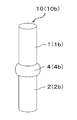
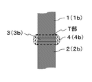
- the ceramic joined body 10 of the present disclosure includes a first base body 1 and a second base body 2, a bonding layer 3 positioned between the first base body 1 and the second base body 2, and A covering layer 4 that covers the bonding layer 3 and is located over the first substrate 1 and the second substrate 2 is provided.
- 1 and 2 show an example in which the first base 1a has a cylindrical shape and the second base 2a has a flat plate shape.
- FIG. 3 and FIG. 4 show examples in which both the first base 1b and the second base 2b are both cylindrical.
- substrate 2 is not limited to a column shape or flat plate shape, You may be arbitrary shapes, such as a cylindrical shape and a square pillar.
- the first base 1 and the second base 2 are made of aluminum nitride ceramics.
- the aluminum nitride ceramic is one in which aluminum nitride accounts for 75% by mass or more out of 100% by mass of all components constituting the aluminum nitride ceramic.
- the materials of the first base 1 and the second base 2 can be confirmed by the following method.
- XRD X-ray diffractometer
- JCPDS card from the obtained 2 ⁇ (2 ⁇ is a diffraction angle) value.
- quantitative analysis of aluminum (Al) is performed using an ICP (Inductively-Coupled-Plasma) emission spectroscopic analyzer (ICP). And if content converted into aluminum nitride (AlN) from the content of aluminum measured by ICP is 75 mass% or more, it is an aluminum nitride ceramic.
- ICP Inductively-Coupled-Plasma emission spectroscopic analyzer
- the nitrogen content is measured using a nitrogen analyzer, and the nitrogen is converted into aluminum nitride, whereby aluminum nitride is obtained.
- the content of may be calculated.
- the joining layer 3 and the covering layer 4 include at least aluminum, calcium, yttrium, and oxygen, and 100% by mass of all components constituting each of the joining layer 3 and the covering layer 4.
- aluminum is contained 21% by mass or more in terms of oxide
- calcium is 21% by mass or more in terms of oxide
- aluminum and calcium are each contained in total of 86% by mass in terms of oxides.
- the coating layer 4 has a higher content of yttrium oxide than the bonding layer 3.
- the joining layer 3 and the coating layer 4 contain the above amounts of aluminum and calcium in terms of oxides, so that the joining strength between the first base 1 and the second base 2 is the same. Will increase.
- the content of each component in terms of oxide in the bonding layer 3 and the coating layer 4 may be calculated by the following method.
- the ceramic joined body 10 is cut so as to have a cross-sectional shape as shown in FIG. 2 or FIG. 4, and the cut surface is processed into a mirror surface using an abrasive such as diamond abrasive grains.
- the bonding layer 3 and the coating layer 4 on the mirror surface are irradiated with an electron beam by an electron beam microanalyzer (EPMA), and the contents of aluminum, calcium and yttrium are measured.
- EPMA electron beam microanalyzer
- the content of each component of the bonding layer 3 is, for example, at least five places in the bonding layer 3 in which the area is 2000 ⁇ m 2 (the length in the horizontal direction is 200 ⁇ m and the length in the vertical direction is 10 ⁇ m). What is necessary is just to measure and to calculate from the average value.
- the content of each component of the coating layer 4 is measured in at least two places in the coating layer 4 such that the area is 22500 ⁇ m 2 (the length in the horizontal direction is 150 ⁇ m and the length in the vertical direction is 150 ⁇ m). Then, it may be calculated from the average value.
- the bonding layer 3 and the covering layer 4 contain aluminum, calcium, yttrium, and oxygen.
- the aluminum content as oxides of calcium and yttrium, from the content of each component was measured by EPMA, respectively aluminum oxide (Al 2 O 3), calcium oxide (CaO), yttrium oxide (Y 2 O It may be calculated by converting to 3 ).
- each of the samples sampled from the bonding layer 3 and the coating layer 4 is measured by ICP, so that the bonding layer 3 and the coating layer 4 can be sampled.
- the contents of aluminum, calcium and yttrium may be measured and converted to oxides.
- the ceramic joined body 10 of the present disclosure when the coating layer 4 contains yttrium in an amount of 3% by mass or more in terms of oxides out of 100% by mass of all components constituting the coating layer 4, an oxide of yttrium Even when the content in terms of conversion is less than 3% by mass, the corrosion resistance of the coating layer 4 is improved. Therefore, if such a configuration is satisfied, the ceramic bonded body 10 according to the present disclosure can be prevented from being deteriorated in bonding strength in a use environment where the ceramic bonded body 10 is exposed to highly corrosive gas or the like.
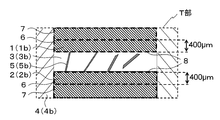
- the ceramic joined body 10 of the present disclosure covers the yttrium segregation phase 5 having an aspect ratio of 8 or more in a cross section (hereinafter referred to as a cross section) along the thickness direction of the bonding layer 3. You may have in the layer 4.
- the yttrium segregation phase 5 in the coating layer 4 is a phase containing a relatively larger amount of yttrium than other portions of the coating layer 4 and having an aspect ratio of 8 or more.
- containing relatively much yttrium means containing more yttrium than the average value of the yttrium content of the coating layer 4.
- the aspect ratio is a value obtained by dividing the major axis of the yttrium segregation phase 5 by the minor axis in the cross section as shown in FIG.
- the major axis means that a straight line is drawn so as to penetrate the yttrium segregation phase 5, and this length is the maximum when the length of a line segment between the two points where the straight line and the outer edge of the yttrium segregation phase 5 intersect is measured. This is the length of the line segment.
- the minor axis is the length of the line segment between the two points where the straight line intersects the outer edge of the yttrium segregation phase 5 when a straight line is drawn at the center of the major segment and perpendicular to the major segment. That is.
- the yttrium segregation phase 5 in the coating layer 4 has a relatively low strength compared to the portion other than the yttrium segregation phase 5, when a crack occurs in the coating layer 4, it occurs in the yttrium segregation phase 5.
- the crack progresses in the longitudinal direction of the yttrium segregation phase 5 due to its elongated shape. At this time, the fracture energy of the crack is consumed in the yttrium segregation phase 5 and the portion other than the yttrium segregation phase 5 is relatively high in strength. It is possible to prevent the cracks from developing.
- the ceramic joined body 10 is cut so as to have a cross-sectional shape as shown in FIG. 2 or FIG. 4, and the cut surface is processed into a mirror surface using an abrasive such as diamond abrasive grains.
- the coating layer 4 on the mirror surface is observed using a scanning electron microscope (SEM), and a photograph of a reflected electron image is taken. In this photograph, a phase having a color tone closer to white than other portions is a phase having a relatively high yttrium content.
- SEM scanning electron microscope
- image analysis software “A Image-kun” registered trademark, manufactured by Asahi Kasei Engineering Co., Ltd.
- image analysis software “A Image-kun” Asahi Kasei Engineering Image analysis is performed by applying the particle analysis method of the image analysis software manufactured by Co., Ltd.).
- the analysis conditions for “A image-kun” for example, the brightness of the particles may be “dark”, the binarization method may be “automatic”, and the shading may be “present”.
- the major axis and minor axis of the phase having a color tone close to white are calculated, and the aspect ratio is calculated by dividing the major axis by the minor axis.
- the yttrium segregation phase 5 has an aspect ratio of 8 or more.
- the joint strength of the ceramic joined body 10 of the present disclosure can be further improved.
- the area ratio occupied by the yttrium segregation phase 5 can be measured by the following method. First, the coating layer 4 is processed into a mirror surface by the above-described method, and the yttrium segregation phase 5 is traced and painted black in the photograph of the reflected electron image of the coating layer 4 taken by SEM. The area ratio can be obtained by performing image analysis using the image analysis software “A image-kun” particle analysis method using the image obtained here.
- the ceramic joined body 10 of the present disclosure may have the yttrium segregation phase 5 having an aspect ratio of 8 or more in the cross-section in the joining layer 3.
- the yttrium segregation phase 5 in the bonding layer 3 is a phase containing a relatively larger amount of yttrium than other portions of the bonding layer 3 and having an aspect ratio of 8 or more.
- containing relatively much yttrium means containing more yttrium than the average value of the yttrium content of the bonding layer 3.
- the bonding strength of the ceramic bonded body 10 of the present disclosure can be further improved.
- At least one of the first base 1 or the second base 2 contains calcium, and from the interface 8 with the joining layer 3 to less than 400 ⁇ m as shown in FIG.
- the content of calcium in the first region 6 corresponding to the oxide in terms of oxide may be greater than the content of calcium in the second region 7 corresponding to 400 ⁇ m or more from the interface 8 in terms of oxide.
- the second region 7 corresponding to 400 ⁇ m or more from the interface 8 in the first substrate 1 is, in other words, a portion of the first substrate 1 excluding the first region 6.
- FIG. 6 is an enlarged view of a T portion shown in FIG. 4, and therefore only a part of the second region 7 is shown in FIG. 6.
- the first substrate 1 in the ceramic joined body 10 of the present disclosure satisfies such a configuration
- the first substrate 1 is made of calcium contained in the first region 6 while maintaining excellent corrosion resistance.
- the chemical affinity with the bonding layer 3 is further improved, and the first member 1 and the bonding layer 3 are firmly bonded.
- substrate 2 satisfy
- the ceramic joined body 10 of the present disclosure is more durable. Excellent in properties.
- region 6 is 0.3 to 1 mass%, for example.
- At least one of the first base 1 or the second base 2 contains yttrium, and the content of the yttrium in the first region 6 in terms of oxide is the second. It may be less than the yttrium oxide content in region 7. If such a configuration is satisfied, the difference in thermal expansion between the first region 6 and the second region 7 due to the difference in calcium content can be reduced. The durability of the body 10 can be improved.
- the content of yttrium in the first region 6 in terms of oxide may be 0.3% by mass or less than the content of yttrium in the second region 7 in terms of oxide.
- the yttrium oxide content in the first region 6 is, for example, 0.2% by mass or less
- the yttrium oxide content in the second region 7 is, for example, 0.5%. It is from 3% by mass to 3% by mass.
- the content of calcium and yttrium in terms of oxides in the first region 6 and the second region 7 may be calculated by the following method.
- the ceramic joined body 10 is cut so as to have a cross-sectional shape as shown in FIG. 2 or FIG. 4, and the cut surface is processed into a mirror surface using an abrasive such as diamond abrasive grains.
- an abrasive such as diamond abrasive grains.
- the first region 6 and the second region 7 in the first substrate 1 and the second substrate 2 are irradiated with an electron beam by EPMA, and the content of each component is measured.
- the content of each component in the first region 6 is, for example, at least 3 in the first region 6 such that the area is 40000 ⁇ m 2 (the length in the horizontal direction is 200 ⁇ m and the length in the vertical direction is 200 ⁇ m). What is necessary is just to measure more than a part and to calculate from the average value.
- the content of each component in the second region 7 is, for example, at least 10 ranges in the second region 7 where the area is 40000 ⁇ m 2 (the length in the horizontal direction is 200 ⁇ m and the length in the vertical direction is 200 ⁇ m). What is necessary is just to measure above and to calculate from the average value. Then, the content of each component was calculated, by converting each of calcium oxide (CaO) and yttrium oxide (Y 2 O 3), may be calculated content as oxides of the respective components.
- CaO calcium oxide
- Y 2 O 3 yttrium oxide
- a first substrate 1 and a second substrate 2 made of aluminum nitride ceramics are produced by the following method.
- a slurry in which aluminum nitride powder, a sintering aid, a binder and a solvent are mixed is spray-dried by a spray drying method to produce granules.
- the obtained granule is filled in a mold and then pressed to produce a molded body.
- the molded body may be manufactured by preparing a green sheet by a doctor blade method using a slurry, forming the green sheet into a desired shape with a mold or a laser, and then laminating the green sheet.
- the molded body is dried and degreased. Then, the 1st base
- the content of calcium in the first region 6 that contains calcium and is less than 400 ⁇ m from the interface 8 with the bonding layer 3 is oxidized in the second region 7 that is equivalent to 400 ⁇ m or more from the interface 8.
- the first substrate 1 and the second substrate 2 may be produced by the following method.
- a green sheet is produced by a doctor blade method using this slurry.
- the green sheet A has a relatively higher proportion of calcium carbonate powder than the green sheet B.
- the green sheet A is formed from the interface with the bonding layer 3 to 400 ⁇ m, and the other parts are made of the green sheet B.
- a molded object is produced by laminating
- first substrate 1 and the second substrate 2 that contain yttrium and have a yttrium oxide content in the first region 6 that is less than the yttrium oxide content in the second region 7.
- yttrium oxide powder is used in addition to calcium carbonate powder as a sintering aid, and the green sheet A is relatively less than the green sheet B in proportion to the yttrium oxide powder. That's fine.
- a first paste for example, an aluminum oxide (Al 2 O 3 ) powder, calcium carbonate (in an organic solvent) is formed on either one of the bonding surfaces of the first substrate 1 and the second substrate 2.
- a first paste for example, an aluminum oxide (Al 2 O 3 ) powder, calcium carbonate (in an organic solvent) is formed on either one of the bonding surfaces of the first substrate 1 and the second substrate 2.
- CaCO 3 yttrium oxide
- Y 2 O 3 yttrium oxide
- acrylic binder acrylic binder
- the joint surfaces are combined and pressed from the direction perpendicular to the joint surface.
- the amount of each powder of aluminum oxide powder, calcium carbonate powder, yttrium oxide powder and other powders for example, silicon oxide powder
- Adjustment is made so that aluminum is 21% by mass or more in terms of oxide, calcium is 21% by mass or more in terms of oxide, and the total of aluminum and calcium in terms of oxides is 86% by mass or more.
- the pressurization may be due to the weight of the member to be joined.
- the surface of the applied first paste is covered, and the second paste (for example, in an organic solvent) that becomes the coating layer 4 is formed so as to cover the surfaces of the first base 1 and the second base 2.
- the second paste for example, in an organic solvent
- an aluminum oxide powder, calcium carbonate powder, yttrium oxide powder, and an acrylic binder and dried at a holding temperature of 100 ° C. to 150 ° C. and a holding time of 0.2 hours to 5 hours.
- the second paste satisfies the above-described ratio of the aluminum oxide powder and the calcium carbonate powder of the first paste except that the ratio of the yttrium oxide powder is larger than that of the first paste.
- the yttrium oxide powder should be 3% by mass or more of the total mass of 100% by mass of the aluminum oxide powder, calcium carbonate powder, yttrium oxide powder and other powders (for example, silicon oxide powder).
- the coating layer 4 contains 3% by mass or more of yttrium in terms of oxides out of 100% by mass of all components constituting the coating layer 4.
- a third paste may be used instead of the second paste described above.
- This third paste is produced by the following method. First, the second paste with the binder amount reduced to about half is sprayed onto a rotating oil-repellent resin disk and dried to obtain granulated powder having an aspect ratio of 8 or more. And the 3rd paste is produced by mixing this granulated powder and the 1st paste.
- the granulated powder in the third paste is dissolved in the organic solvent, it remains as a phase that generally maintains the shape of the granulated powder, and this becomes the yttrium segregation phase 5.
- the area ratio which the yttrium segregation phase 5 accounts in the coating layer 4 can be made into arbitrary values by adjusting the ratio of granulated powder and the 1st paste.
- a fourth paste may be used instead of the first paste described above.
- This fourth paste is produced by the following method. First, the first paste with the binder amount reduced to about half is sprayed onto a rotating oil-repellent resin disc and dried to obtain granulated powder having an aspect ratio of 8 or more. And the 4th paste is produced by mixing this granulated powder and the 1st paste.
- the granulated powder in the fourth paste is dissolved in the organic solvent, it remains as a phase that generally maintains the shape of the granulated powder, and this becomes the yttrium segregation phase 5.
- the above-mentioned granulated powder is scattered on the bonding surface. If the first paste is applied so that the granular powder is exposed, the yttrium segregation phase 5 that contacts both the first substrate 1 and the second substrate 2 can be obtained in the bonding layer 3.
- a heat treatment is performed in a nitrogen gas atmosphere at a holding temperature of 1400 ° C. or more and 1570 ° C. or less and a holding time of 0.2 hours or more and 5 hours or less, thereby obtaining the ceramic joined body 10 of the present disclosure. it can.
- a first substrate and a second substrate made of aluminum nitride ceramics were produced by the following method.
- a slurry in which aluminum nitride powder, a sintering aid, a binder and a solvent were mixed was spray-dried by a spray drying method to produce granules.
- a sintering aid a mixed powder of yttrium oxide powder and calcium carbonate powder was used.
- the mixing ratio of the aluminum nitride powder and the sintering aid was such that the aluminum nitride powder was 94% by mass, the yttrium oxide powder was 5.8% by mass, and the calcium carbonate powder was 0.2% by mass.
- the first substrate was a columnar shape with a diameter of 26 mm and a length of 70 mm
- the second substrate was a flat plate with a size of 60 mm ⁇ 50 mm ⁇ 7 mm.
- a first paste to be a bonding layer and a second paste to be a coating layer were produced.
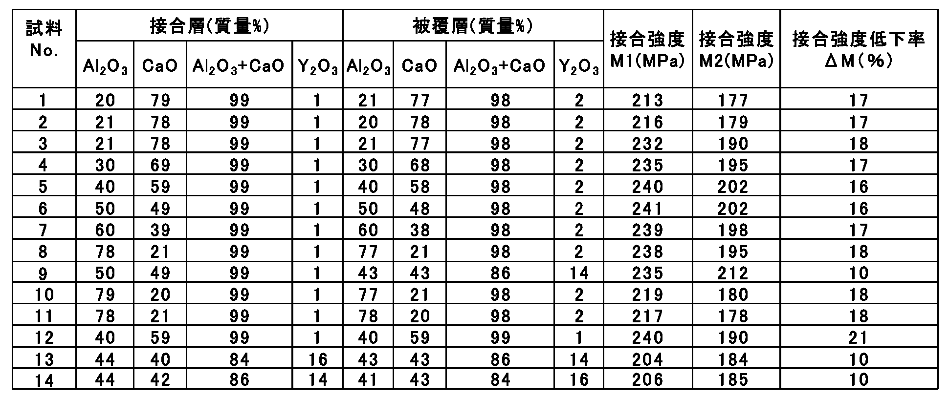
- the amounts of aluminum oxide powder, calcium carbonate powder and yttrium oxide powder are adjusted so as to have the composition of the bonding layer and the coating layer shown in Table 1, and the total amount of these powders is 100 mass. It was prepared by adding 7 parts by mass of terpineol as an organic solvent and 10 parts by mass of an acrylic resin as a binder.
- the first paste is applied to the end surface, which is the bonding surface of the first substrate, so that the bonding layer has a thickness of 50 ⁇ m, and then placed on the second substrate and pressed from the direction perpendicular to the bonding surface. did. Then, in a pressurized state, the surface of the applied first paste is covered and the second paste is applied so as to cover the surfaces of the first base and the second base, the holding temperature is 120 ° C., and the holding time is 2 hours. Dried. After drying, each sample was obtained by performing heat treatment in a nitrogen gas atmosphere at a holding temperature of 1510 ° C. and a holding time of 2 hours.
- the bonding strength of each sample was measured. First, with the second substrate of each sample fixed with a jig, a load was applied in a direction parallel to the bonding surface to the end of the first substrate that was not bonded. Then, the load was increased with time, and the bonding strength M1 when the first substrate was peeled from the second substrate was measured.
- each sample was placed in a reactive ion etching apparatus, and SF 6 gas was introduced into the apparatus to maintain the pressure in the apparatus at 10 Pa. Then, plasma was generated by high frequency of 13.56 MHz and 1 kW, and each sample was brought into contact with the plasma for 3 hours. The temperature of each sample was set to be room temperature (25 ° C.). Thereafter, the bonding strength M2 of each sample was measured by the method of measuring the bonding strength M1 described above.
- Sample No. 5 and 12 in the relationship of the yttrium oxide content of the bonding layer and the coating layer, the sample No. 12 and Sample No. where the bonding layer ⁇ the coating layer. No. 5 had a lower bonding strength reduction rate ⁇ M.
- the bonding layer and the coating layer contain at least aluminum, calcium, yttrium, and oxygen, and aluminum is 21% by mass in terms of oxides out of 100% by mass of the total components constituting each of the bonding layer and the coating layer.
- aluminum is 21% by mass or more in terms of oxide
- aluminum and calcium are each 86% by mass or more in terms of oxide
- the content of yttrium in terms of oxide in the coating layer is greater than that of the bonding layer.
- Sample No. 1 5 is the same as the production method of Sample No. 15 is sample No. 1 of Example 1. 5 is the same sample.
- samples having a coating layer having an yttrium segregation phase and different area ratios occupied by the yttrium segregation phase were prepared, and durability and corrosion resistance were evaluated.
- sample No. 2 in Example 2 was used except that a coating layer was formed using a third paste described later instead of the second paste. This is the same as the manufacturing method 16.
- the third paste was prepared by the following method. First, sample No. 2 of Example 2 in which the acrylic resin as the binder was reduced to half. 16 second paste was sprayed on a rotating oil-repellent resin disc and dried to obtain granulated powder having an aspect ratio of 8 or more. And the 3rd paste was produced by adjusting and mixing the ratio of granulated powder and the 1st paste so that the area ratio which an yttrium segregation phase accounts may have a value shown in Table 3.
- the composition of the coating layer of each sample is the sample No.
- the amount of each powder of the first paste was also adjusted so as to be the same as the composition of 16 coating layers.
- each sample was cut so as to have a cross-sectional shape as shown in FIG. 1B, and the cut surface was processed into a mirror surface using an abrasive such as diamond abrasive grains.
- the coating layer on this mirror surface was observed using SEM, and a photograph of a reflected electron image was taken. And in this photograph, the phase having a color tone closer to white than other portions was traced and painted black.
- image analysis was performed by applying the particle analysis method of the image analysis software “A image-kun”, and the aspect ratio of the phase having a color tone close to white was calculated.
- phase with the calculated aspect ratio of 8 or more is the yttrium segregation phase
- image analysis is performed by particle analysis of the image analysis software “A image kun” using only the black image traced from the yttrium segregation phase.
- the area ratio occupied by the yttrium segregation phase in the coating layer was calculated.
- Example 3 the measurement of the bonding strengths M1 and M2 and the calculation of the bonding strength reduction rate ⁇ M were performed. As a result, the bonding strength reduction rate ⁇ M of each sample was 13%, although the bonding strength M1 of each sample was different.
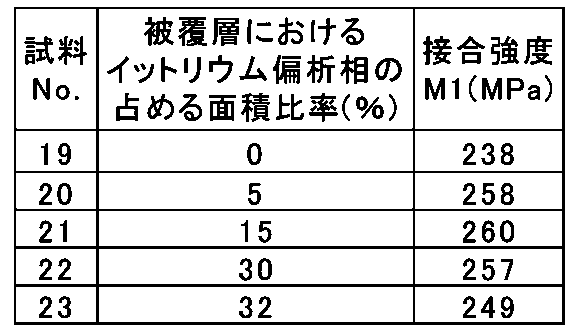
- Table 3 for comparison, Sample No. of Example 2 which does not have an yttrium segregation phase in the coating layer. 16 for sample no. 19 is described.
- sample No. 19 has a bonding strength M1 of 238 MPa, whereas sample No. Since the bonding strength M1 of 20 to 23 was 249 MPa or more, it was found that the ceramic bonded body having an yttrium segregation phase in the coating layer had more excellent durability.
- sample no. Among samples 20 to 23, sample no. Since the bonding strength M1 of 20 to 22 is 257 MPa or more, the ceramic joined body in which the area ratio of the yttrium segregation phase in the coating layer is 5% or more and 30% or less has further excellent durability. I understood.
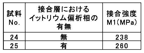
- Sample No. having an yttrium segregation phase in the bonding layer was used. 25 was produced, and durability and corrosion resistance were evaluated. Sample No. As a production method of Sample 25 of Example 3, except that a bonding layer was formed using a fourth paste described later instead of the first paste. This is the same as the manufacturing method of No. 19.
- the fourth paste was produced by the following method. First, the sample No. of Example 3 in which the acrylic resin as the binder was reduced to half. The first paste of 19 was sprayed on a rotating oil-repellent resin disk and dried to obtain granulated powder having an aspect ratio of 8 or more. And the 4th paste was produced by mixing this granulated powder and the 1st paste.
- sample No. Sample No. 19 was prepared in exactly the same way as in No. 19. 24 was produced.
- sample no. 24 has a bonding strength M1 of 238 MPa, whereas the sample No. Since the joining strength M1 of 25 is 260 MPa, it was found that the ceramic joined body having an yttrium segregation phase in the joining layer has more excellent durability.
- Sample No. 27 is the sample No. of Example 4.
- the granulated powder produced from the first paste is scattered on the end surface serving as the bonding surface of the first substrate, and then this granulated powder is exposed.
- the first paste was applied as described above.
- Sample No. 26 and 27 the method for confirming the presence or absence of the yttrium segregation phase in the bonding layer in Example 4 was used to confirm the presence or absence of the yttrium segregation phase in contact with both the first substrate and the second substrate in the bonding layer. did.
- sample No. 26 has a bonding strength M1 of 260 MPa, while sample No. Since the bonding strength M1 of 27 is 277 MPa, the ceramic bonded body having an yttrium segregation phase in contact with both the first substrate and the second substrate in the bonding layer has more excellent durability. I understood it.
- samples having different contents in terms of oxide of calcium in the first region and the second region in both the first substrate and the second substrate were prepared, and durability and corrosion resistance were evaluated.
- the sample No. of Example 4 was used except that the first substrate and the second substrate were produced by the following method. This is the same as the manufacturing method of No. 25.
- a slurry in which aluminum nitride powder, a sintering aid, a binder and a solvent were mixed was spray-dried by a spray drying method to produce granules.
- a sintering aid a mixed powder of yttrium oxide powder and calcium carbonate powder was used.
- a green sheet was produced by a doctor blade method using a slurry.
- the green sheets two types of green sheets A and B with different ratios of calcium carbonate powder were produced. Specifically, after firing, the calcium content becomes the content shown in Table 6 in terms of calcium oxide (CaO), and the yttrium content is 2.5% by mass in terms of yttrium oxide (Y 2 O 3 ), Green sheets A and B were prepared by changing the proportions of aluminum nitride powder, yttrium oxide powder and calcium carbonate powder so that the balance was aluminum nitride.
- these green sheets A and B are processed with a mold and, after firing, laminated so that the green sheet A is formed from the interface with the bonding layer to 400 ⁇ m, and the other portions are formed of the green sheet B.
- a molded body was prepared. Thereafter, the molded body was degreased and fired in a nitrogen gas atmosphere at a temperature of 1750 ° C. for 3 hours to obtain a first base and a second base made of an aluminum nitride ceramic.
- samples having different contents in terms of oxide of yttrium in the first region and the second region in both the first substrate and the second substrate were prepared, and durability was evaluated.
- the ratio of yttrium oxide powder was changed so that the yttrium content became the content shown in Table 7 in terms of yttrium oxide (Y 2 O 3 ) conversion.
- the sample No. in Example 6. 30 is the same as the manufacturing method.
- the bonding strength M1 was measured. As a result, the bonding strength M1 of each sample was all 271 MPa.
- each sample was placed in a reactive ion etching apparatus, and SF 6 gas was introduced into the apparatus to maintain the pressure in the apparatus at 10 Pa. Then, plasma was generated by high frequency of 13.56 MHz and 1 kW, and each sample was brought into contact with the plasma for 3 hours. Here, the temperature of each sample was set to be 200 ° C. Thereafter, the bonding strength M3 of each sample was measured. The results are shown in Table 7.
Landscapes
- Chemical & Material Sciences (AREA)
- Engineering & Computer Science (AREA)
- Ceramic Engineering (AREA)
- Materials Engineering (AREA)
- Structural Engineering (AREA)
- Organic Chemistry (AREA)
- Manufacturing & Machinery (AREA)
- Ceramic Products (AREA)
Abstract
Description


2、2a、2b:第2基体
3、3a、3b:接合層
4、4a、4b:被覆層
5、5a、5b:イットリウム偏析相
6:第1領域
7:第2領域
8:界面
10、10a、10b:セラミック接合体
Claims (8)
- 第1基体と、第2基体と、前記第1基体および前記第2基体の間に位置する接合層と、該接合層を覆うとともに前記第1基体および前記第2基体にわたって位置する被覆層とを備え、
前記第1基体および前記第2基体は、窒化アルミニウム質セラミックスからなり、
前記接合層および前記被覆層は、少なくとも、アルミニウム、カルシウム、イットリウムおよび酸素を含み、前記接合層および前記被覆層のそれぞれを構成する全成分100質量%のうち、前記アルミニウムを酸化物換算で21質量%以上、前記カルシウムを酸化物換算で21質量%以上、かつ、前記アルミニウムおよび前記カルシウムをそれぞれ酸化物換算した合計で86質量%以上であり、
前記被覆層は、前記イットリウムの酸化物換算での含有量が前記接合層よりも多いセラミック接合体。 - 前記被覆層は、該被覆層を構成する全成分100質量%のうち、前記イットリウムを酸化物換算で3質量%以上含有している請求項1に記載のセラミック接合体。
- 前記被覆層は、前記接合層の厚み方向に沿った断面において、アスペクト比が8以上であるイットリウム偏析相を有する請求項1または請求項2に記載のセラミック接合体。
- 前記被覆層における、前記イットリウム偏析相の占める面積比率が5%以上30%以下である請求項3に記載のセラミック接合体。
- 前記接合層は、該接合層の厚み方向に沿った断面において、アスペクト比が8以上であるイットリウム偏析相を有する請求項1乃至請求項4のいずれかに記載のセラミック接合体。
- 前記接合層において、前記イットリウム偏析相は、前記第1基体および前記第2基体の両方と接触している請求項5に記載のセラミック接合体。
- 前記第1基体または前記第2基体の少なくとも一方は、カルシウムを含有しており、前記接合層との界面から400μm未満までにあたる第1領域における前記カルシウムの酸化物換算での含有量が、前記界面から400μm以上にあたる第2領域における前記カルシウムの酸化物換算での含有量よりも多い請求項1乃至請求項6のいずれかに記載のセラミック接合体。
- 前記第1基体または前記第2基体の少なくとも一方は、イットリウムを含有しており、前記第1領域における前記イットリウムの酸化物換算での含有量が、前記第2領域における前記イットリウムの酸化物換算での含有量よりも少ない請求項7に記載のセラミック接合体。
Priority Applications (3)
| Application Number | Priority Date | Filing Date | Title |
|---|---|---|---|
| EP17756656.9A EP3406583B1 (en) | 2016-02-26 | 2017-02-24 | Ceramic bonded body |
| US16/079,562 US20190202746A1 (en) | 2016-02-26 | 2017-02-24 | Ceramic bonded body |
| JP2018501802A JP6556323B2 (ja) | 2016-02-26 | 2017-02-24 | セラミック接合体 |
Applications Claiming Priority (2)
| Application Number | Priority Date | Filing Date | Title |
|---|---|---|---|
| JP2016035769 | 2016-02-26 | ||
| JP2016-035769 | 2016-02-26 |
Publications (1)
| Publication Number | Publication Date |
|---|---|
| WO2017146222A1 true WO2017146222A1 (ja) | 2017-08-31 |
Family
ID=59686308
Family Applications (1)
| Application Number | Title | Priority Date | Filing Date |
|---|---|---|---|
| PCT/JP2017/007163 WO2017146222A1 (ja) | 2016-02-26 | 2017-02-24 | セラミック接合体 |
Country Status (4)
| Country | Link |
|---|---|
| US (1) | US20190202746A1 (ja) |
| EP (1) | EP3406583B1 (ja) |
| JP (1) | JP6556323B2 (ja) |
| WO (1) | WO2017146222A1 (ja) |
Cited By (1)
| Publication number | Priority date | Publication date | Assignee | Title |
|---|---|---|---|---|
| JPWO2018021491A1 (ja) * | 2016-07-27 | 2019-05-23 | 京セラ株式会社 | セラミック接合体 |
Families Citing this family (1)
| Publication number | Priority date | Publication date | Assignee | Title |
|---|---|---|---|---|
| WO2021204496A1 (de) * | 2020-04-06 | 2021-10-14 | Saint-Gobain Glass France | Verfahren zur herstellung einer keramischen biegeform für glasscheiben |
Citations (5)
| Publication number | Priority date | Publication date | Assignee | Title |
|---|---|---|---|---|
| JPH10167850A (ja) * | 1996-10-08 | 1998-06-23 | Ngk Insulators Ltd | 窒化アルミニウム質基材の接合体の製造方法およびこれに使用する接合助剤 |
| JPH10273370A (ja) * | 1997-01-30 | 1998-10-13 | Ngk Insulators Ltd | 窒化アルミニウム質セラミックス基材の接合体、窒化アルミニウム質セラミックス基材の接合体の製造方法及び接合剤 |
| JP2000114355A (ja) * | 1998-09-30 | 2000-04-21 | Kyocera Corp | 板状セラミック体と筒状セラミック体との接合構造体及びこの接合構造体を用いた加熱装置 |
| JP2006169092A (ja) * | 2004-11-16 | 2006-06-29 | Ngk Insulators Ltd | 接合剤、窒化アルミニウム接合体及びその製造方法 |
| WO2008065980A1 (fr) * | 2006-11-27 | 2008-06-05 | Tokuyama Corporation | Procédé de fabrication d'un produit de jonction de nitrure d'aluminium |
Family Cites Families (9)
| Publication number | Priority date | Publication date | Assignee | Title |
|---|---|---|---|---|
| US3469729A (en) * | 1966-06-30 | 1969-09-30 | Westinghouse Electric Corp | Sealing compositions for bonding ceramics to metals |
| US4326038A (en) * | 1977-06-29 | 1982-04-20 | Ngk Insulators, Ltd. | Sealing composition and sealing method |
| US5321335A (en) * | 1992-08-03 | 1994-06-14 | General Electric Company | Alumina, calcia, yttria sealing composition |
| JP4070752B2 (ja) * | 1997-01-30 | 2008-04-02 | 日本碍子株式会社 | 窒化アルミニウム質セラミックス基材の接合剤 |
| JP3607552B2 (ja) * | 2000-02-14 | 2005-01-05 | 日本特殊陶業株式会社 | 金属−セラミック接合体及びその製造方法 |
| JP2006169082A (ja) * | 2004-12-20 | 2006-06-29 | Rispi 21 Kankyo Kaihatsu Kenkyusho:Kk | 不燃材料および不燃性硬化剤 |
| JP4942963B2 (ja) * | 2005-08-18 | 2012-05-30 | 日本碍子株式会社 | 耐食性部材及びその製造方法 |
| JP6001761B2 (ja) * | 2013-02-27 | 2016-10-05 | 京セラ株式会社 | セラミック接合体および流路体 |
| US20170267591A1 (en) * | 2014-07-10 | 2017-09-21 | Ceramtec Gmbh | Laminated ceramic molded article having recesses |
-
2017
- 2017-02-24 EP EP17756656.9A patent/EP3406583B1/en active Active
- 2017-02-24 US US16/079,562 patent/US20190202746A1/en not_active Abandoned
- 2017-02-24 WO PCT/JP2017/007163 patent/WO2017146222A1/ja active Application Filing
- 2017-02-24 JP JP2018501802A patent/JP6556323B2/ja active Active
Patent Citations (5)
| Publication number | Priority date | Publication date | Assignee | Title |
|---|---|---|---|---|
| JPH10167850A (ja) * | 1996-10-08 | 1998-06-23 | Ngk Insulators Ltd | 窒化アルミニウム質基材の接合体の製造方法およびこれに使用する接合助剤 |
| JPH10273370A (ja) * | 1997-01-30 | 1998-10-13 | Ngk Insulators Ltd | 窒化アルミニウム質セラミックス基材の接合体、窒化アルミニウム質セラミックス基材の接合体の製造方法及び接合剤 |
| JP2000114355A (ja) * | 1998-09-30 | 2000-04-21 | Kyocera Corp | 板状セラミック体と筒状セラミック体との接合構造体及びこの接合構造体を用いた加熱装置 |
| JP2006169092A (ja) * | 2004-11-16 | 2006-06-29 | Ngk Insulators Ltd | 接合剤、窒化アルミニウム接合体及びその製造方法 |
| WO2008065980A1 (fr) * | 2006-11-27 | 2008-06-05 | Tokuyama Corporation | Procédé de fabrication d'un produit de jonction de nitrure d'aluminium |
Non-Patent Citations (1)
| Title |
|---|
| See also references of EP3406583A4 * |
Cited By (1)
| Publication number | Priority date | Publication date | Assignee | Title |
|---|---|---|---|---|
| JPWO2018021491A1 (ja) * | 2016-07-27 | 2019-05-23 | 京セラ株式会社 | セラミック接合体 |
Also Published As
| Publication number | Publication date |
|---|---|
| US20190202746A1 (en) | 2019-07-04 |
| EP3406583B1 (en) | 2021-07-14 |
| JP6556323B2 (ja) | 2019-08-07 |
| JPWO2017146222A1 (ja) | 2018-12-13 |
| EP3406583A1 (en) | 2018-11-28 |
| EP3406583A4 (en) | 2019-01-09 |
Similar Documents
| Publication | Publication Date | Title |
|---|---|---|
| CN107074663B (zh) | 烧结体 | |
| TWI564266B (zh) | A laminated structure, a member for a semiconductor manufacturing apparatus, and a method for manufacturing the laminated structure | |
| JP5872998B2 (ja) | アルミナ焼結体、それを備える部材、および半導体製造装置 | |
| KR20180103509A (ko) | 잔류응력이 없는 탄화규소 접합체 및 그 제조방법 | |
| JP6556323B2 (ja) | セラミック接合体 | |
| TWI746617B (zh) | 成膜用材料及皮膜 | |
| CN110997594A (zh) | 烧结体的制造方法、结构体以及复合结构体 | |
| JP2010006641A (ja) | 耐食性部材およびこれを用いた処理装置 | |
| KR102102625B1 (ko) | 세라믹 접합체 | |
| JP2015067472A (ja) | セラミック接合体 | |
| JP5761636B2 (ja) | アルミナ接合体及びアルミナ焼結体の接合方法 | |
| TWI763933B (zh) | 氧化鋁質燒結體及其製造方法 | |
| WO2018021491A1 (ja) | セラミック接合体 | |
| JP2009029686A (ja) | 耐食性部材およびその製造方法ならびに処理装置 | |
| JP5067751B2 (ja) | セラミック接合体及びその製造方法 | |
| JP7231367B2 (ja) | アルミナ質焼結体 | |
| JP6864470B2 (ja) | セラミック接合体 | |
| JP5809884B2 (ja) | 炭化ホウ素含有セラミックス接合体及び該接合体の製造方法 | |
| KR102354650B1 (ko) | 알루미나질 소결체 및 그의 제조 방법 | |
| JP7154912B2 (ja) | アルミナ質焼結体及びその製造方法 | |
| JP4092122B2 (ja) | 半導体製造装置用部材及びその製造方法 | |
| JP6462807B2 (ja) | セラミック接合体 | |
| Slawik et al. | Co-Sintering behaviour of zirconia-ferritic steel composites |
Legal Events
| Date | Code | Title | Description |
|---|---|---|---|
| WWE | Wipo information: entry into national phase |
Ref document number: 2018501802 Country of ref document: JP |
|
| WWE | Wipo information: entry into national phase |
Ref document number: 2017756656 Country of ref document: EP |
|
| NENP | Non-entry into the national phase |
Ref country code: DE |
|
| ENP | Entry into the national phase |
Ref document number: 2017756656 Country of ref document: EP Effective date: 20180823 |
|
| 121 | Ep: the epo has been informed by wipo that ep was designated in this application |
Ref document number: 17756656 Country of ref document: EP Kind code of ref document: A1 |