WO2017134959A1 - 駆動装置 - Google Patents
駆動装置 Download PDFInfo
- Publication number
- WO2017134959A1 WO2017134959A1 PCT/JP2016/088607 JP2016088607W WO2017134959A1 WO 2017134959 A1 WO2017134959 A1 WO 2017134959A1 JP 2016088607 W JP2016088607 W JP 2016088607W WO 2017134959 A1 WO2017134959 A1 WO 2017134959A1
- Authority
- WO
- WIPO (PCT)
- Prior art keywords
- cover
- lead wire
- housing
- terminal
- drive device
- Prior art date
Links
Images


Classifications
-
- H—ELECTRICITY
- H02—GENERATION; CONVERSION OR DISTRIBUTION OF ELECTRIC POWER
- H02K—DYNAMO-ELECTRIC MACHINES
- H02K5/00—Casings; Enclosures; Supports
- H02K5/04—Casings or enclosures characterised by the shape, form or construction thereof
- H02K5/10—Casings or enclosures characterised by the shape, form or construction thereof with arrangements for protection from ingress, e.g. water or fingers
-
- B—PERFORMING OPERATIONS; TRANSPORTING
- B62—LAND VEHICLES FOR TRAVELLING OTHERWISE THAN ON RAILS
- B62D—MOTOR VEHICLES; TRAILERS
- B62D5/00—Power-assisted or power-driven steering
- B62D5/04—Power-assisted or power-driven steering electrical, e.g. using an electric servo-motor connected to, or forming part of, the steering gear
- B62D5/0403—Power-assisted or power-driven steering electrical, e.g. using an electric servo-motor connected to, or forming part of, the steering gear characterised by constructional features, e.g. common housing for motor and gear box
- B62D5/0406—Power-assisted or power-driven steering electrical, e.g. using an electric servo-motor connected to, or forming part of, the steering gear characterised by constructional features, e.g. common housing for motor and gear box including housing for electronic control unit
-
- H—ELECTRICITY
- H02—GENERATION; CONVERSION OR DISTRIBUTION OF ELECTRIC POWER
- H02K—DYNAMO-ELECTRIC MACHINES
- H02K11/00—Structural association of dynamo-electric machines with electric components or with devices for shielding, monitoring or protection
- H02K11/30—Structural association with control circuits or drive circuits
- H02K11/33—Drive circuits, e.g. power electronics
-
- H—ELECTRICITY
- H02—GENERATION; CONVERSION OR DISTRIBUTION OF ELECTRIC POWER
- H02K—DYNAMO-ELECTRIC MACHINES
- H02K5/00—Casings; Enclosures; Supports
- H02K5/04—Casings or enclosures characterised by the shape, form or construction thereof
- H02K5/22—Auxiliary parts of casings not covered by groups H02K5/06-H02K5/20, e.g. shaped to form connection boxes or terminal boxes
- H02K5/225—Terminal boxes or connection arrangements
-
- H—ELECTRICITY
- H02—GENERATION; CONVERSION OR DISTRIBUTION OF ELECTRIC POWER
- H02K—DYNAMO-ELECTRIC MACHINES
- H02K7/00—Arrangements for handling mechanical energy structurally associated with dynamo-electric machines, e.g. structural association with mechanical driving motors or auxiliary dynamo-electric machines
- H02K7/08—Structural association with bearings
- H02K7/083—Structural association with bearings radially supporting the rotary shaft at both ends of the rotor
-
- B—PERFORMING OPERATIONS; TRANSPORTING
- B62—LAND VEHICLES FOR TRAVELLING OTHERWISE THAN ON RAILS
- B62D—MOTOR VEHICLES; TRAILERS
- B62D5/00—Power-assisted or power-driven steering
- B62D5/04—Power-assisted or power-driven steering electrical, e.g. using an electric servo-motor connected to, or forming part of, the steering gear
-
- H—ELECTRICITY
- H02—GENERATION; CONVERSION OR DISTRIBUTION OF ELECTRIC POWER
- H02K—DYNAMO-ELECTRIC MACHINES
- H02K11/00—Structural association of dynamo-electric machines with electric components or with devices for shielding, monitoring or protection
- H02K11/20—Structural association of dynamo-electric machines with electric components or with devices for shielding, monitoring or protection for measuring, monitoring, testing, protecting or switching
- H02K11/21—Devices for sensing speed or position, or actuated thereby
-
- H—ELECTRICITY
- H02—GENERATION; CONVERSION OR DISTRIBUTION OF ELECTRIC POWER
- H02K—DYNAMO-ELECTRIC MACHINES
- H02K2211/00—Specific aspects not provided for in the other groups of this subclass relating to measuring or protective devices or electric components
- H02K2211/03—Machines characterised by circuit boards, e.g. pcb
-
- H—ELECTRICITY
- H02—GENERATION; CONVERSION OR DISTRIBUTION OF ELECTRIC POWER
- H02K—DYNAMO-ELECTRIC MACHINES
- H02K3/00—Details of windings
- H02K3/46—Fastening of windings on the stator or rotor structure
- H02K3/50—Fastening of winding heads, equalising connectors, or connections thereto
Definitions
- the present disclosure relates to a drive device including a motor and a control unit.
- a drive device in which a motor and a control unit for controlling the motor are integrally provided is known.
- a motor housing is provided with a hole (hereinafter referred to as a lead wire insertion hole) through which a lead wire that connects the motor coil and the control unit is passed.
- a lead wire insertion hole communicates the inside and outside of the housing, there is a concern that foreign matter generated when the lead wire and the control unit are electrically connected by, for example, soldering or the like enters the housing through the lead wire insertion hole.
- the drive device disclosed in Patent Document 1 includes a seal member that closes the lead wire insertion hole. The seal member is sandwiched and held between the bottom portion of the bottomed cylindrical case constituting the housing and the frame end.
- the seal member is only necessary for preventing foreign matter from entering the housing when the lead wire and the control unit are connected, and is unnecessary when the drive device is used. Therefore, it is required to reduce the number of seal members in order to improve the assemblability and reduce the number of parts.
- the present disclosure has been made in view of the above-described points, and an object of the present disclosure is to enter a foreign substance into the housing when the lead wire and the control unit are connected without providing a seal member in the lead wire insertion hole of the housing. It is providing the drive device which can suppress this.
- a drive device of the present disclosure is provided in a housing, a stator fixed in the housing, a rotor provided rotatably with respect to the stator, a cover attached to an outer wall of the housing, and the cover. And a control unit for controlling energization of the stator coil, a terminal extending from the control unit, and a lead wire extending from the coil.
- the terminal passes through the cover.
- the lead wire penetrates the housing and the cover, and is electrically connected to the terminal outside the cover.
- the drive device configured as described above can connect the lead wire and the terminal with, for example, solder after the cover is attached to the housing. At this time, when connecting the lead wire and the terminal, the lead wire insertion hole of the housing is blocked by the cover. Therefore, without providing a seal member in the lead wire insertion hole of the housing, it is possible to suppress the entry of foreign matter such as solder scraps generated during soldering or spatter generated during welding into the housing through the lead wire insertion hole. be able to. Since it is not necessary to provide a seal member, it is possible to improve the assembling property and reduce the number of parts.
- FIG. 10 A drive device according to a first embodiment of the present disclosure is shown in FIG.
- the drive device 10 is used as a drive source of an electric power steering device that assists the steering of the vehicle driver.
- the drive device 10 is an electromechanical integrated drive device in which a motor 11 and a control unit 12 for controlling the motor 11 are integrally provided.
- the motor 11 is a three-phase brushless motor, and includes a stator 21, a rotor 22, and a housing 23 for housing them.
- the stator 21 has a stator core 24 fixed in the housing 23 and two sets of three-phase coils (hereinafter referred to as coils) 25 assembled to the stator core 24.
- coils three-phase coils
- One lead wire 261, 262, 263 is extended from each phase winding constituting the coil 25.
- lead wire 26 when the lead wires 261, 262, and 263 are not distinguished, they are simply referred to as “lead wire 26”.
- the rotor 22 has a rotating shaft 32 supported by bearings 29 and 31 and a rotor core 33 fitted to the rotating shaft 32.
- the rotor 22 is rotatable with respect to the stator 21 inside the stator 21.
- a detected member 34 made of a permanent magnet is provided at one end of the rotating shaft 32.
- the detected member 34 is used by a rotation angle sensor 42 described later to detect the rotation angle of the rotor 22.
- the housing 23 includes a cylindrical case 35, a first frame end 36 provided at one end of the case 35, and a second frame end 37 provided at the other end of the case 35.
- the first frame end 36 and the second frame end 37 sandwich the case 35 and are fastened to each other by a plurality of bolts (not shown).
- the bearing 29 is provided at the center of the first frame end 36, and the bearing 31 is provided at the center of the second frame end 37.
- the first frame end 36 has a lead wire insertion hole 38 through which the lead wire 26 is inserted. In the present embodiment, the lead wire insertion hole 38 is provided for each lead wire 26.
- a cover 39 is attached to the outer wall of the housing 23 and on the wall of the first frame engine 36 on the control unit 12 side.
- the cover 39 has a cup shape. The cover 39 protects the control unit 12 from external impacts and prevents entry of dust, water, and the like into the control unit 12.
- the control unit 12 includes various electronic components 41 to 46 and a substrate 47 on which they are mounted.
- the substrate 47 is, for example, a printed circuit board, and is provided to face the first frame end 36. Of the two main surfaces of the substrate 47, the surface facing the first frame end 36 is a first main surface 48, and the opposite surface is a second main surface 49.
- the first main surface 48 of the substrate 47 includes a plurality of switching elements 41 that constitute inverters corresponding to the two systems of coils 25, a rotation angle sensor 42 that detects the position of the rotor 22, and the switching elements 41.
- an integrated circuit 43 that outputs a drive signal is mounted.
- the rotation angle sensor 42 faces the detected member 34.
- the switching element 41 and the integrated circuit 43 are in contact with the first frame end 36 in a state where heat can be radiated through a heat radiating gel (not shown).
- the first frame end 36 also functions as a heat sink.
- a microcomputer 44 that calculates a command value for the power supplied to each phase winding of the coil 13 based on the position of the rotor 22 and the like, power supply to the inverter by storing electric charge And a choke coil 46 constituting a filter circuit together with the capacitor 45 are mounted.
- Terminals 511, 512, and 513 extend from the substrate 47 one by one corresponding to the lead wires 261, 262, and 263, respectively.
- terminal 51 When the terminals 511, 512, and 513 are not distinguished, they are simply referred to as “terminal 51”.
- the terminal 51 is electrically connected to the lead wire 26 and the substrate 47 by soldering. Detailed configurations of the lead wire 26 and the terminal 51 will be described later.
- the drive device 10 configured in this manner rotates the rotor 22 by sequentially switching energization to the respective phase windings of the coil 25 based on the detection signal of the rotation angle sensor 42 to generate a rotating magnetic field.
- the controller 12 of the driving device 10 is mounted on one side in the axial direction with respect to the motor 11. Therefore, it can be avoided that the control unit 12 directly receives the vibration of the motor 11.
- the first frame end 36 to which the control unit 12 is fixed is made of, for example, aluminum die casting and is precisely formed. Therefore, the positional accuracy between the control unit 12 and the motor 11 is significantly improved, and the heat generated by the control unit 12 can be effectively released.
- Each phase winding of the coil 25 and the substrate 47 are connected to each other via the lead wire 26 and the terminal 51.
- the first phase winding of the coil 25 is connected to the substrate 47 via the lead wire 261 and the terminal 511.
- the second phase winding of the coil 25 is connected to the substrate 47 via the lead wire 262 and the terminal 512.
- the third phase winding of the coil 25 is connected to the substrate 47 via the lead wire 263 and the terminal 513.
- the lead wire 26 penetrates the first frame end 36 and the cover 39.
- the terminal 51 passes through the cover 39.
- the cover 39 has a through hole 521 through which the lead wire 261 and the terminal 511 are inserted, a through hole 522 through which the lead wire 262 and the terminal 512 are inserted, and a through hole 523 through which the lead wire 263 and the terminal 513 are inserted. have.
- through holes 52 Of the inner wall surface of the through hole 52, the control unit 12 side is a tapered surface 53 having an inner diameter that is larger toward the control unit 12 side.
- the one end 54 of the lead wire 26 and the one end 55 of the terminal 51 protrude outside the cover 39, and are electrically connected to each other by soldering outside the cover 39.
- the driving apparatus 10 further includes a shielding member 56 provided on the outer wall of the cover 39 so as to shield the lead wire 26 and the terminal 51 from the external space.
- the shielding member 56 is indicated by a two-dot chain line for convenience.
- the shielding member 56 has a cup shape, and the opening end portion is fixed to the cover 39 by, for example, bonding or the like while covering the one end 54 of the lead wire 26 and the one end 55 of the terminal 51.
- the drive device 10 configured as described above is assembled in the following procedures (1) to (6).
- (1) The stator 21 and the rotor 22 are assembled to the housing 23.
- the lead wire 26 is provided so as to protrude from the first frame end 36 to the outside of the housing 23.
- (2) The electronic components 41 to 46 and the terminal 51 are mounted on the substrate 47.
- (3) The substrate 47 is fixed to the first frame end 36.
- (4) The cover 39 is attached to the first frame end 36.
- the lead wire 26 and the terminal 51 are inserted into the through hole 52 of the cover 39, and the opening end portion of the cover 39 is combined and fixed to the first frame end 36.
- the tapered surface 53 functions as a guide portion that guides the lead wire 26 and the terminal 51 to the through hole 52.
- One end 54 of the lead wire 26 and one end 55 of the terminal 51 are electrically connected to each other by soldering outside the cover 39. At this time, soldering is performed in a state where a gap between the lead wire 26 and the through hole 52 is closed by a lid-like jig (not shown). (6) The shielding member 56 is fixed to the cover 39.
- the driving apparatus 10 includes the housing 23, the stator 21 fixed in the housing 23, the rotor 22 provided to be rotatable with respect to the stator 21, and the housing. 23, a cover 39 attached to the outer wall 23, a control unit 12 that is provided in the cover 39, controls the energization of the coil 25 of the stator 21, and extends from the control unit 12, and passes through the cover 39. And a lead wire 26 that extends from the coil 25, penetrates the housing 23, penetrates the cover 39, and is electrically connected to the terminal 51 outside the cover 39.
- the drive device 10 configured in this manner can connect the lead wire 26 and the terminal 51 with, for example, solder after the cover 39 is attached to the housing 23.
- the lead wire insertion hole 38 of the housing 23 is blocked by the cover 39 when the lead wire 26 and the terminal 51 are connected. Accordingly, it is possible to suppress the entry of the solder scrap generated when soldering into the housing 23 through the lead wire insertion hole 38 without providing a seal member in the lead wire insertion hole 38 of the housing 23. Since it is not necessary to provide a seal member, it is possible to improve the assembling property and reduce the number of parts. Since it is not necessary to provide a seal member in the lead wire insertion hole 38, it is possible to improve the assembling property and reduce the number of parts.
- the shielding member 61 is made of resin fused to one end 54 of the lead wire 26 and one end 55 of the terminal 51. That is, the shielding member 61 is a resin that has solidified after adhering to the one ends 54 and 55 in a molten state.
- the cover 65 includes a recess 66 that is recessed toward the inside of the cover 65.
- the through hole 52 is formed at the bottom of the recess 66.
- One end 54 of the lead wire 26 outside the cover 65 and one end 55 of the terminal 51 outside the cover 65 are accommodated in the recess 67 of the recess 66. That is, the one ends 54 and 55 do not protrude outward from the recess 67 of the recess 66.
- a shielding member 68 is fitted in the recess 66.
- the lead wire 26 and the terminal 51 can be connected outside the cover 65 without providing a projection on the cover 65. .
- the shielding member 71 is provided in the recess 67 of the recess 66 and is made of resin fused to one end 54 of the lead wire 26 and one end 55 of the terminal 51. Become.
- the through hole 76 of the cover 75 is formed to have substantially the same size as a combination of one end 54 of the lead wire 26 and one end 55 of the terminal 51. Yes. Therefore, when soldering the lead wire 26 and the terminal 51, it is not necessary to close the through hole 76 using a jig.
- the cover 81 is integrated with a cover main body portion 82 having a through hole 52 through which the lead wire 26 and the terminal 51 are inserted, and an inner wall surface of the through hole 52. And has an elastic portion 83 in contact with the lead wire 26 and the terminal 51 so as to close the gap of the through hole 52.
- the cover body 82 is made of metal.
- the elastic portion 83 is made of a material having a relatively large elasticity, such as rubber.
- the elastic part 83 which closes the gap between the through hole 52 and the lead wire 26 and the terminal 51 is provided, when the lead wire 26 and the terminal 51 are soldered, the through hole 52 is formed using a jig. There is no need to close it.
- the cover main body portion 82 can be made of metal, so that the strength of the cover 81 can be increased and the heat dissipation can be increased.
- one lead wire insertion hole of the housing may be provided for a plurality of lead wires.
- one cover through hole may be provided for a plurality of lead wires.
- the cross-sectional shape of the through hole of the cover is not limited to a rectangle, and may be, for example, a circle.
- the inner wall surface of the through hole of the cover may not have a tapered surface.
- the entire inner wall surface of the through hole of the cover may be a tapered surface.
- the lead wire and the terminal may overlap in the circumferential direction, or may overlap in another direction.
- the fixing method of the shielding member is not limited to adhesion, and other methods such as screw fastening or fitting may be used.
- the motor three-phase coil may be one set or three or more sets.
- the drive device may be applied to devices other than the electric power steering device.
Abstract
駆動装置(10)は、ハウジング(23)の外壁に取り付けられているカバー(39)と、カバー(39)内に設けられている制御部(12)と、制御部(12)から延び出しており、カバー(39)を貫通しているターミナル(51)と、コイル(25)から延び出しており、ハウジング(23)を貫通するとともにカバー(39)を貫通しており、カバー(39)外でターミナル(51)に電気的に接続されているリード線(26)とを備える。そのため、カバー(39)をハウジング(23)に取り付けた後にリード線(26)とターミナル(51)とを接続可能である。このとき、リード線挿通孔(38)はカバー(39)で遮られることになり、はんだ屑がリード線挿通孔(38)を通じてハウジング(23)内に侵入することを抑制することができる。
Description
本願は、2016年2月1日に出願された日本国特許出願第2016-16925号に基づくものであり、この開示をもってその内容を本明細書中に開示したものとする。
本開示は、モータおよび制御部を備える駆動装置に関する。
従来、モータおよびこれを制御する制御部が一体に設けられた駆動装置が知られている。この種の駆動装置において、モータのハウジングには、モータのコイルと制御部とをつなぐリード線を通す孔(以下、リード線挿通孔)が設けられる。リード線挿通孔がハウジング内外を連通させる場合、リード線と制御部とを例えばはんだ付け等により電気的に接続するときに生じる異物がリード線挿通孔を通じてハウジング内に入り込むことが懸念される。これに対して、特許文献1に開示された駆動装置は、リード線挿通孔を塞ぐシール部材を備える。シール部材は、ハウジングを構成する有底筒状のケースの底部とフレームエンドとの間に挟まれて保持されている。
ところが、上記シール部材は、リード線と制御部との接続時におけるハウジング内への異物侵入防止のために必要なだけであって、駆動装置の使用時には不要なものである。そのため、組み付け性の向上および部品点数削減のためにシール部材を削減することが求められている。
本開示は、上述の点に鑑みてなされたものであり、その目的は、ハウジングのリード線挿通孔にシール部材を設けることなく、リード線と制御部との接続時におけるハウジング内への異物侵入を抑制することができる駆動装置を提供することである。
本開示の駆動装置は、ハウジングと、ハウジング内で固定されているステータと、ステータに対して回転可能に設けられているロータと、ハウジングの外壁に取り付けられているカバーと、カバー内に設けられており、ステータのコイルの通電を制御する制御部と、制御部から延び出しているターミナルと、コイルから延び出しているリード線とを備える。ターミナルは、カバーを貫通している。リード線は、ハウジングを貫通するとともにカバーを貫通しており、カバー外でターミナルに電気的に接続されている。
このように構成された駆動装置は、カバーをハウジングに取り付けた後にリード線とターミナルとを例えばはんだ等で接続することが可能である。この際、リード線とターミナルとの接続時には、ハウジングのリード線挿通孔はカバーで遮られることになる。したがって、ハウジングのリード線挿通孔にシール部材を設けることなく、はんだ付けを行うときに生じるはんだ屑や溶接するときに生じるスパッタ等の異物がリード線挿通孔を通じてハウジング内に侵入することを抑制することができる。シール部材を設ける必要がないことから、組み付け性の向上および部品点数削減が可能となる。
本開示についての上記目的およびその他の目的、特徴や利点は、添付の図面を参照しながら下記の詳細な記述により、より明確になる。
以下、本開示の複数の実施形態を図面に基づき説明する。複数の実施形態において実質的に同一の構成には同一の符号を付して説明を省略する。
[第1実施形態]
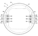
本開示の第1実施形態による駆動装置を図1に示す。駆動装置10は、車両の運転者の操舵を補助する電動パワーステアリング装置の駆動源として用いられる。
本開示の第1実施形態による駆動装置を図1に示す。駆動装置10は、車両の運転者の操舵を補助する電動パワーステアリング装置の駆動源として用いられる。
先ず、駆動装置10の全体的な構成について図1、図2を参照して説明する。
駆動装置10は、モータ11およびこれを制御する制御部12が一体に設けられている機電一体型の駆動装置である。
モータ11は、3相ブラシレスモータであって、ステータ21、ロータ22、およびそれらを収容するハウジング23を備えている。
ステータ21は、ハウジング23内で固定されているステータコア24と、ステータコア24に組み付けられている2組の三相コイル(以下、コイル)25とを有している。コイル25を構成する各相巻線からは、それぞれ1本ずつリード線261、262、263が延び出している。以降、リード線261、262、263を区別しない場合、単に「リード線26」と記載する。
ロータ22は、軸受29、31により支持されている回転軸32と、回転軸32に嵌めつけられているロータコア33とを有している。ロータ22は、ステータ21の内側で当該ステータ21に対して回転可能である。回転軸32の一端には、永久磁石からなる被検出部材34が設けられている。この被検出部材34は、後述の回転角センサ42がロータ22の回転角を検出するために用いられる。
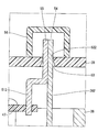
ハウジング23は、筒状のケース35と、ケース35の一端に設けられている第1フレームエンド36と、ケース35の他端に設けられている第2フレームエンド37とを有している。第1フレームエンド36および第2フレームエンド37は、ケース35を挟持しており、図示しない複数のボルトにより互いに締結されている。軸受29は第1フレームエンド36の中央部に設けられており、軸受31は第2フレームエンド37の中央部に設けられている。第1フレームエンド36は、リード線26が挿通しているリード線挿通孔38を有している。本実施形態では、リード線挿通孔38は、リード線26毎に設けられている。
ハウジング23の外壁であって、第1フレームエン36の制御部12側の壁部には、カバー39が取り付けられている。本実施形態では、カバー39はカップ状である。カバー39は、外部の衝撃から制御部12を保護したり、制御部12への埃や水等の浸入を防止したりする。
制御部12は、各種の電子部品41~46と、それらが実装された基板47とを備えている。
基板47は、例えばプリント基板であり、第1フレームエンド36と対向するように設けられている。基板47の2つの主面のうち、第1フレームエンド36に対向している面を第1主面48とし、その反対側の面を第2主面49とする。
基板47の第1主面48には、二系統のコイル25にそれぞれ対応するインバータを構成している複数のスイッチング素子41、ロータ22の位置を検出する回転角センサ42、および、スイッチング素子41に対して駆動信号を出力する集積回路43等が実装されている。回転角センサ42は、被検出部材34と対向している。スイッチング素子41および集積回路43は、図示しない放熱ゲルを介して第1フレームエンド36に放熱可能な状態で当接している。第1フレームエンド36はヒートシンクとしても機能する。
基板47の第2主面49には、ロータ22の位置等に基づいてコイル13の各相巻線に供給する電力についての指令値を演算するマイコン44、電荷を蓄えることでインバータへの電力供給を補助するコンデンサ45、および、コンデンサ45と共にフィルタ回路を構成しているチョークコイル46等が実装されている。
基板47からは、各リード線261、262、263に対応して1本ずつターミナル511、512、513が延び出している。以降、ターミナル511、512、513を区別しない場合、単に「ターミナル51」と記載する。ターミナル51は、はんだ付けによりリード線26と基板47とに電気的に接続されている。リード線26およびターミナル51の詳細な構成については後述する。
このように構成された駆動装置10は、回転角センサ42の検出信号に基づきコイル25の各相巻線への通電を順次切り替えて回転磁界を発生させて、ロータ22を回転させる。駆動装置10の制御部12はモータ11に対して軸方向の一方側に搭載されている。そのため、制御部12がモータ11の振動を直接受けることを回避することができる。また、制御部12が固定されている第1フレームエンド36は、例えばアルミダイカスト製であり、精密に形成されている。そのため、制御部12とモータ11との位置精度が格段に向上するとともに、制御部12の発する熱を効果的に放出可能である。
次に、駆動装置10の特徴的な構成について図1~図3を参照して説明する。
コイル25の各相巻線と基板47とは、リード線26およびターミナル51を介して互いにつながっている。具体的には、コイル25の第1相巻線は、リード線261およびターミナル511を介して基板47に接続されている。コイル25の第2相巻線は、リード線262およびターミナル512を介して基板47に接続されている。コイル25の第3相巻線は、リード線263およびターミナル513を介して基板47に接続されている。
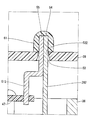
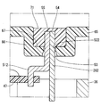
リード線26は、第1フレームエンド36を貫通するとともにカバー39を貫通している。ターミナル51は、カバー39を貫通している。カバー39は、リード線261およびターミナル511が挿通している通孔521、リード線262およびターミナル512が挿通している通孔522、および、リード線263およびターミナル513が挿通している通孔523を有している。以降、通孔521、522、523を区別しない場合、単に「通孔52」と記載する。通孔52の内壁面のうち制御部12側は、制御部12側ほど内径が大きいテーパ面53である。
リード線26の一端54およびターミナル51の一端55は、カバー39外に突き出しており、カバー39外ではんだ付けにより互いに電気的に接続されている。
駆動装置10は、リード線26およびターミナル51と外部空間とを遮るようにカバー39の外壁に設けられている遮蔽部材56をさらに備える。図2では、便宜上、遮蔽部材56を二点鎖線で示している。遮蔽部材56は、カップ状であり、リード線26の一端54およびターミナル51の一端55に被せられつつ、開口端部がカバー39に例えば接着等で固定されている。
このように構成された駆動装置10は、次の(1)~(6)の手順で組み付けられる。
(1)ステータ21およびロータ22がハウジング23に組み付けられる。このとき、リード線26は第1フレームエンド36からハウジング23外へ突き出すように設けられる。
(2)電子部品41~46およびターミナル51が基板47に実装される。
(3)基板47が第1フレームエンド36に固定される。
(4)カバー39が第1フレームエンド36に取り付けられる。このとき、リード線26およびターミナル51がカバー39の通孔52に挿入されつつ、カバー39の開口端部が第1フレームエンド36に組み合わせられて固定される。テーパ面53は、リード線26およびターミナル51を通孔52に案内するガイド部として機能する。
(5)リード線26の一端54とターミナル51の一端55とがカバー39外ではんだ付けにより互いに電気的に接続される。このとき、リード線26と通孔52との隙間が図示しない蓋状の治具により塞がれた状態で、はんだ付けが行われる。
(6)遮蔽部材56がカバー39に固定される。
(効果)
以上説明したように、第1実施形態では、駆動装置10は、ハウジング23と、ハウジング23内で固定されているステータ21と、ステータ21に対して回転可能に設けられているロータ22と、ハウジング23の外壁に取り付けられているカバー39と、カバー39内に設けられており、ステータ21のコイル25の通電を制御する制御部12と、制御部12から延び出しており、カバー39を貫通しているターミナル51と、コイル25から延び出しており、ハウジング23を貫通するとともにカバー39を貫通しており、カバー39外でターミナル51に電気的に接続されているリード線26と、を備える。
以上説明したように、第1実施形態では、駆動装置10は、ハウジング23と、ハウジング23内で固定されているステータ21と、ステータ21に対して回転可能に設けられているロータ22と、ハウジング23の外壁に取り付けられているカバー39と、カバー39内に設けられており、ステータ21のコイル25の通電を制御する制御部12と、制御部12から延び出しており、カバー39を貫通しているターミナル51と、コイル25から延び出しており、ハウジング23を貫通するとともにカバー39を貫通しており、カバー39外でターミナル51に電気的に接続されているリード線26と、を備える。
このように構成された駆動装置10は、カバー39をハウジング23に取り付けた後にリード線26とターミナル51とを例えばはんだ等で接続することが可能である。この際、リード線26とターミナル51との接続時には、ハウジング23のリード線挿通孔38はカバー39で遮られることになる。したがって、ハウジング23のリード線挿通孔38にシール部材を設けることなく、はんだ付けを行うときに生じるはんだ屑がリード線挿通孔38を通じてハウジング23内に侵入することを抑制することができる。シール部材を設ける必要がないことから、組み付け性を向上させること、および部品点数を削減することができる。リード線挿通孔38にシール部材を設ける必要がないことから、組み付け性の向上および部品点数削減が可能となる。
[第2実施形態]
本開示の第2実施形態では、図4に示すように、遮蔽部材61は、リード線26の一端54およびターミナル51の一端55に融着させられた樹脂からなる。つまり、遮蔽部材61は、溶融状態で一端54、55に付着したのち固化した樹脂である。
本開示の第2実施形態では、図4に示すように、遮蔽部材61は、リード線26の一端54およびターミナル51の一端55に融着させられた樹脂からなる。つまり、遮蔽部材61は、溶融状態で一端54、55に付着したのち固化した樹脂である。
[第3実施形態]
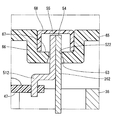
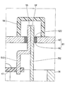
本開示の第3実施形態では、図5に示すように、カバー65は、当該カバー65の内側へ凹む凹部66を有している。通孔52は、凹部66の底部に形成されている。リード線26のカバー65外の一端54およびターミナル51のカバー65外の一端55は、凹部66の凹み67内に収まっている。つまり、一端54、55は、凹部66の凹み67から外側に突出していない。凹部66には、遮蔽部材68が嵌め付けられている。
本開示の第3実施形態では、図5に示すように、カバー65は、当該カバー65の内側へ凹む凹部66を有している。通孔52は、凹部66の底部に形成されている。リード線26のカバー65外の一端54およびターミナル51のカバー65外の一端55は、凹部66の凹み67内に収まっている。つまり、一端54、55は、凹部66の凹み67から外側に突出していない。凹部66には、遮蔽部材68が嵌め付けられている。
このように一端54、55がカバー65の凹部66の凹み67内に収まっているため、カバー65に突起物を設けることなく、カバー65外でリード線26とターミナル51とを接続することができる。
[第4実施形態]
本開示の第4実施形態では、図6に示すように、遮蔽部材71は、凹部66の凹み67に設けられ、リード線26の一端54およびターミナル51の一端55に融着させられた樹脂からなる。
本開示の第4実施形態では、図6に示すように、遮蔽部材71は、凹部66の凹み67に設けられ、リード線26の一端54およびターミナル51の一端55に融着させられた樹脂からなる。
[第5実施形態]
本開示の第5実施形態では、図7に示すように、カバー75の通孔76は、リード線26の一端54とターミナル51の一端55とを組み合わせたものとほぼ同じ大きさに形成されている。そのため、リード線26とターミナル51とをはんだ付けするとき、治具を用いて通孔76を塞ぐ必要がない。
本開示の第5実施形態では、図7に示すように、カバー75の通孔76は、リード線26の一端54とターミナル51の一端55とを組み合わせたものとほぼ同じ大きさに形成されている。そのため、リード線26とターミナル51とをはんだ付けするとき、治具を用いて通孔76を塞ぐ必要がない。
[第6実施形態]
本開示の第6実施形態では、図8に示すように、カバー81は、リード線26およびターミナル51が挿通している通孔52を有するカバー本体部82と、通孔52の内壁面に一体に結合しており、通孔52の隙間を塞ぐようにリード線26およびターミナル51に接触している弾性部83とを有している。カバー本体部82は金属からなる。弾性部83は例えばゴム等の比較的大きな弾性をもつ材料からなる。
本開示の第6実施形態では、図8に示すように、カバー81は、リード線26およびターミナル51が挿通している通孔52を有するカバー本体部82と、通孔52の内壁面に一体に結合しており、通孔52の隙間を塞ぐようにリード線26およびターミナル51に接触している弾性部83とを有している。カバー本体部82は金属からなる。弾性部83は例えばゴム等の比較的大きな弾性をもつ材料からなる。
このように通孔52とリード線26およびターミナル51との隙間を塞ぐ弾性部83が設けられているため、リード線26とターミナル51とをはんだ付けするとき、治具を用いて通孔52を塞ぐ必要がない。また、カバー本体部82を金属から構成して、カバー81の強度を上げるとともに放熱性を高めることができる。
[他の実施形態]
本開示の他の実施形態では、ハウジングのリード線挿通孔は、複数のリード線に対して1つ設けられてもよい。
本開示の他の実施形態では、ハウジングのリード線挿通孔は、複数のリード線に対して1つ設けられてもよい。
本開示の他の実施形態では、カバーの通孔は、複数のリード線に対して1つ設けられてもよい。
本開示の他の実施形態では、カバーの通孔の横断面形状は、矩形に限らず、例えば円形等であってもよい。
本開示の他の実施形態では、カバーの通孔の内壁面はテーパ面を有していなくてもよい。または、カバーの通孔の内壁面の全体がテーパ面であってもよい。
本開示の他の実施形態では、リード線とターミナルとが周方向に重なっていてもよいし、他の方向に重なっていてもよい。
本開示の他の実施形態では、遮蔽部材の固定方法は、接着に限らず、例えばねじ締結または嵌め込み等の他の方法を用いてもよい。
本開示の他の実施形態では、モータの三相コイルは、1組であってもよいし、3組以上であってもよい。
本開示の他の実施形態では、駆動装置は、電動パワーステアリング装置以外に適用してもよい。
本開示は、上述した実施形態に限定されるものではなく、本開示の趣旨を逸脱しない範囲で種々の形態で実施可能である。
Claims (5)
- ハウジング(23)と、
前記ハウジング(23)内で固定されているステータ(21)と、
前記ステータ(21)に対して回転可能に設けられているロータ(22)と、
前記ハウジング(23)外で当該ハウジング(23)の外壁に取り付けられているカバー(39、65、75、81)と、
前記カバー(39、65、75、81)内に設けられており、前記ステータ(21)のコイル(25)の通電を制御する制御部(12)と、
前記制御部(12)から延び出しており、前記カバー(39、65、75、81)を貫通しているターミナル(511、512、513)と、
前記コイル(25)から延び出しており、前記ハウジング(23)を貫通するとともに前記カバー(39、65、75、81)を貫通しており、前記カバー(39、65、75、81)外で前記ターミナル(511、512、513)に電気的に接続されているリード線(261、262、263)と、
を備える駆動装置。 - 前記カバー(65)は、当該カバー(65)の内側へ凹む凹部(66)を有しており、
前記リード線(262)の前記カバー(65)外の一端(54)および前記ターミナル(512)の前記カバー(65)外の一端(55)は、前記凹部(66)の凹み(67)内に収まっている請求項1に記載の駆動装置。 - 前記リード線(262)および前記ターミナル(512)と外部空間とを遮るように前記凹み(67)に設けられている遮蔽部材(68、71)をさらに備える請求項2に記載の駆動装置。
- 前記カバー(81)は、少なくとも前記リード線(262)が挿通している通孔(522)を有するカバー本体部(82)と、前記通孔(522)の内壁面または縁部に結合しており、前記通孔(522)と前記リード線(262)との隙間を塞ぐように前記リード線(262)に接触している弾性部(83)とを有している請求項1~3のいずれか一項に記載の駆動装置。
- 前記カバー本体部(82)は金属からなる請求項4に記載の駆動装置。
Priority Applications (1)
| Application Number | Priority Date | Filing Date | Title |
|---|---|---|---|
| US16/073,892 US11050318B2 (en) | 2016-02-01 | 2016-12-26 | Drive device |
Applications Claiming Priority (2)
| Application Number | Priority Date | Filing Date | Title |
|---|---|---|---|
| JP2016016925A JP6520739B2 (ja) | 2016-02-01 | 2016-02-01 | 駆動装置 |
| JP2016-016925 | 2016-02-01 |
Publications (1)
| Publication Number | Publication Date |
|---|---|
| WO2017134959A1 true WO2017134959A1 (ja) | 2017-08-10 |
Family
ID=59500314
Family Applications (1)
| Application Number | Title | Priority Date | Filing Date |
|---|---|---|---|
| PCT/JP2016/088607 WO2017134959A1 (ja) | 2016-02-01 | 2016-12-26 | 駆動装置 |
Country Status (3)
| Country | Link |
|---|---|
| US (1) | US11050318B2 (ja) |
| JP (1) | JP6520739B2 (ja) |
| WO (1) | WO2017134959A1 (ja) |
Cited By (1)
| Publication number | Priority date | Publication date | Assignee | Title |
|---|---|---|---|---|
| CN110233544A (zh) * | 2018-03-06 | 2019-09-13 | 本田技研工业株式会社 | 旋转电机 |
Families Citing this family (9)
| Publication number | Priority date | Publication date | Assignee | Title |
|---|---|---|---|---|
| US10256758B2 (en) * | 2014-11-26 | 2019-04-09 | Kohler Co. | Printed circuit board based exciter |
| DE102016214032A1 (de) * | 2016-07-29 | 2018-02-01 | Volkswagen Aktiengesellschaft | Verfahren zur Herstellung eines Elektromotors und Elektromotor |
| JP7024320B2 (ja) * | 2016-11-07 | 2022-02-24 | 株式会社デンソー | モータ |
| JP6879870B2 (ja) * | 2017-09-07 | 2021-06-02 | 日立Astemo株式会社 | 電動駆動装置及び電動パワーステアリング装置 |
| KR102027396B1 (ko) * | 2018-03-05 | 2019-11-15 | 계양전기 주식회사 | 전자제어모듈 일체형 모터조립체 |
| JP7199628B2 (ja) * | 2018-09-20 | 2023-01-06 | マーレ インターナショナル ゲゼルシャフト ミット ベシュレンクテル ハフツング | 電動モータ |
| JP7392599B2 (ja) | 2020-07-14 | 2023-12-06 | 株式会社デンソー | 回転電機 |
| JP2023051603A (ja) | 2021-09-30 | 2023-04-11 | 日本電産株式会社 | モータ |
| JP2023051602A (ja) | 2021-09-30 | 2023-04-11 | 日本電産株式会社 | モータ |
Citations (4)
| Publication number | Priority date | Publication date | Assignee | Title |
|---|---|---|---|---|
| JP2010263768A (ja) * | 2009-04-09 | 2010-11-18 | Nsk Ltd | 電動パワーステアリング装置 |
| JP2014138489A (ja) * | 2013-01-17 | 2014-07-28 | Nissan Motor Co Ltd | インバータ付きモータ |
| JP2015154673A (ja) * | 2014-02-18 | 2015-08-24 | 株式会社デンソー | 回転電機 |
| JP2016019335A (ja) * | 2014-07-07 | 2016-02-01 | 日本精工株式会社 | 電動モータとその制御装置との接合構造及び接合方法、並びに、これを用いたアクチュエータ、電動パワーステアリング装置、及び、車両 |
Family Cites Families (2)
| Publication number | Priority date | Publication date | Assignee | Title |
|---|---|---|---|---|
| JP2010041871A (ja) | 2008-08-07 | 2010-02-18 | Mitsuba Corp | ブラシレスモータ |
| JP6011557B2 (ja) | 2014-01-31 | 2016-10-19 | 株式会社デンソー | 駆動装置 |
-
2016
- 2016-02-01 JP JP2016016925A patent/JP6520739B2/ja active Active
- 2016-12-26 US US16/073,892 patent/US11050318B2/en active Active
- 2016-12-26 WO PCT/JP2016/088607 patent/WO2017134959A1/ja active Application Filing
Patent Citations (4)
| Publication number | Priority date | Publication date | Assignee | Title |
|---|---|---|---|---|
| JP2010263768A (ja) * | 2009-04-09 | 2010-11-18 | Nsk Ltd | 電動パワーステアリング装置 |
| JP2014138489A (ja) * | 2013-01-17 | 2014-07-28 | Nissan Motor Co Ltd | インバータ付きモータ |
| JP2015154673A (ja) * | 2014-02-18 | 2015-08-24 | 株式会社デンソー | 回転電機 |
| JP2016019335A (ja) * | 2014-07-07 | 2016-02-01 | 日本精工株式会社 | 電動モータとその制御装置との接合構造及び接合方法、並びに、これを用いたアクチュエータ、電動パワーステアリング装置、及び、車両 |
Cited By (1)
| Publication number | Priority date | Publication date | Assignee | Title |
|---|---|---|---|---|
| CN110233544A (zh) * | 2018-03-06 | 2019-09-13 | 本田技研工业株式会社 | 旋转电机 |
Also Published As
| Publication number | Publication date |
|---|---|
| US11050318B2 (en) | 2021-06-29 |
| US20190044406A1 (en) | 2019-02-07 |
| JP2017139830A (ja) | 2017-08-10 |
| JP6520739B2 (ja) | 2019-05-29 |
Similar Documents
| Publication | Publication Date | Title |
|---|---|---|
| WO2017134959A1 (ja) | 駆動装置 | |
| JP5748917B2 (ja) | 電動式駆動装置および電動式駆動装置の製造方法 | |
| EP2549627B1 (en) | Electric drive device and electric power steering device having same mounted therein | |
| JP3638269B2 (ja) | 電動式パワーステアリング装置 | |
| JP5764459B2 (ja) | 駆動装置 | |
| JP4203055B2 (ja) | 電動式パワーステアリング装置 | |
| JP6514135B2 (ja) | 電動駆動装置及び電動パワーステアリング装置 | |
| US7445081B2 (en) | Electric power steering apparatus | |
| JP5927836B2 (ja) | 駆動装置 | |
| JP5634610B2 (ja) | 電動式駆動装置 | |
| US20160204670A1 (en) | Drive device | |
| JP6514136B2 (ja) | 電動駆動装置及び電動パワーステアリング装置 | |
| JP6522536B2 (ja) | 電動駆動装置及び電動パワーステアリング装置 | |
| US20140035445A1 (en) | Rotating electric machine and electric power steering apparatus | |
| JP4252486B2 (ja) | 電動式パワーステアリング装置 | |
| JP6702212B2 (ja) | 駆動装置 | |
| JP2015089216A (ja) | 回転電機 | |
| JP2017159770A (ja) | 電動駆動装置及び電動パワーステアリング装置 | |
| WO2017141637A1 (ja) | 駆動装置 | |
| WO2019159406A1 (ja) | 電子制御装置及び電動駆動装置 | |
| WO2020110261A1 (ja) | 電動駆動装置 | |
| KR20200108051A (ko) | 전동 구동 장치 및 전동 파워 스티어링 장치 |
Legal Events
| Date | Code | Title | Description |
|---|---|---|---|
| 121 | Ep: the epo has been informed by wipo that ep was designated in this application |
Ref document number: 16889442 Country of ref document: EP Kind code of ref document: A1 |
|
| NENP | Non-entry into the national phase |
Ref country code: DE |
|
| 122 | Ep: pct application non-entry in european phase |
Ref document number: 16889442 Country of ref document: EP Kind code of ref document: A1 |