WO2017119243A1 - 供試体特性推定方法及び供試体特性推定装置 - Google Patents
供試体特性推定方法及び供試体特性推定装置 Download PDFInfo
- Publication number
- WO2017119243A1 WO2017119243A1 PCT/JP2016/087057 JP2016087057W WO2017119243A1 WO 2017119243 A1 WO2017119243 A1 WO 2017119243A1 JP 2016087057 W JP2016087057 W JP 2016087057W WO 2017119243 A1 WO2017119243 A1 WO 2017119243A1
- Authority
- WO
- WIPO (PCT)
- Prior art keywords
- transfer function
- specimen
- dynamometer
- inertia
- moment
- Prior art date
- Legal status (The legal status is an assumption and is not a legal conclusion. Google has not performed a legal analysis and makes no representation as to the accuracy of the status listed.)
- Ceased
Links
Images



Classifications
-
- G—PHYSICS
- G01—MEASURING; TESTING
- G01M—TESTING STATIC OR DYNAMIC BALANCE OF MACHINES OR STRUCTURES; TESTING OF STRUCTURES OR APPARATUS, NOT OTHERWISE PROVIDED FOR
- G01M15/00—Testing of engines
- G01M15/04—Testing internal-combustion engines
- G01M15/042—Testing internal-combustion engines by monitoring a single specific parameter not covered by groups G01M15/06 - G01M15/12
-
- G—PHYSICS
- G01—MEASURING; TESTING
- G01M—TESTING STATIC OR DYNAMIC BALANCE OF MACHINES OR STRUCTURES; TESTING OF STRUCTURES OR APPARATUS, NOT OTHERWISE PROVIDED FOR
- G01M1/00—Testing static or dynamic balance of machines or structures
- G01M1/10—Determining the moment of inertia
-
- G—PHYSICS
- G01—MEASURING; TESTING
- G01M—TESTING STATIC OR DYNAMIC BALANCE OF MACHINES OR STRUCTURES; TESTING OF STRUCTURES OR APPARATUS, NOT OTHERWISE PROVIDED FOR
- G01M15/00—Testing of engines
- G01M15/02—Details or accessories of testing apparatus
-
- G—PHYSICS
- G01—MEASURING; TESTING
- G01M—TESTING STATIC OR DYNAMIC BALANCE OF MACHINES OR STRUCTURES; TESTING OF STRUCTURES OR APPARATUS, NOT OTHERWISE PROVIDED FOR
- G01M15/00—Testing of engines
- G01M15/04—Testing internal-combustion engines
- G01M15/042—Testing internal-combustion engines by monitoring a single specific parameter not covered by groups G01M15/06 - G01M15/12
- G01M15/046—Testing internal-combustion engines by monitoring a single specific parameter not covered by groups G01M15/06 - G01M15/12 by monitoring revolutions
-
- G—PHYSICS
- G01—MEASURING; TESTING
- G01L—MEASURING FORCE, STRESS, TORQUE, WORK, MECHANICAL POWER, MECHANICAL EFFICIENCY, OR FLUID PRESSURE
- G01L3/00—Measuring torque, work, mechanical power, or mechanical efficiency, in general
- G01L3/02—Rotary-transmission dynamometers
Definitions
- the present invention relates to a specimen property estimation method and a specimen property estimation apparatus for estimating specimen characteristics, in particular, moment of inertia.
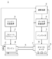
- FIG. 6 is a diagram showing a configuration of the test system 100 for the engine 160 using the dynamometer 150.
- the test system 100 includes an engine 160 as a specimen and a dynamometer 150 connected by a shaft 170, a throttle actuator 110 and an engine control device 120 that control the output of the engine 160, and an inverter 130 that controls the output of the dynamometer 150. And a dynamometer control device 140.
- the test system 100 controls the torque and speed of the dynamometer 150 using the dynamometer control device 140 while controlling the throttle opening of the engine 160 using the engine control device 120. Fuel economy, exhaust purification performance, etc. are evaluated.
- the test system 100 measures the characteristics of the engine 160, particularly the moment of inertia of the engine 160, before performing the test for evaluating the performance as described above, and controls the torque control and speed control in the dynamometer control device 140. May be used as a parameter.
- the output torque of the dynamometer 150 is subjected to vibration control while the rotational speed of the engine 160 is controlled to be substantially constant, and at this time, the rotating shaft that connects the engine 160 and the dynamometer 150 is used.
- Data on the generated shaft torque and the rotational speed of the dynamometer 150 is recorded for a certain period of time. Further, a transfer function with the shaft torque as an input and an output of the rotational speed of the dynamometer 150 is estimated from this data. The moment of inertia of engine 160 is measured.
- the loss due to rotational friction of the engine 160 may depend not only on the steady value of the rotational speed of the engine 160 but also on the history of changes in the rotational speed.
- the moment of inertia cannot be accurately estimated.
- JP 2006-300683 A JP 2003-121307 A Japanese Patent Laid-Open No. 2008-203551
- the moment of inertia can be measured with high accuracy.
- the measurement since it is necessary to repeatedly perform the calculation until the evaluation function converges based on the nonlinear programming method, the measurement may take time.
- An object of the present invention is to provide a specimen specific estimation method and a specimen characteristic estimation apparatus capable of measuring a moment of inertia in a short time while considering a loss due to rotational friction in the specimen.
- a test system (for example, test system 1 described later) is a dynamometer (for example, described later) coupled to a specimen (for example, engine E to be described later) and a connection shaft (for example, connection shaft S to be described later).
- Dynamometer D a shaft torque sensor (for example, a shaft torque sensor 7 described later) for detecting a shaft torque generated on the connecting shaft, and a rotation for detecting the number of rotations of the output shaft of the specimen or the dynamometer.
- a number detection device (for example, a dynamo rotation speed sensor 8 or an engine rotation speed sensor C described later).
- the specimen characteristic estimation method of the present invention estimates the moment of inertia with the output axis of the specimen as a rotation axis using the test system, and the dynamometer is obtained by oscillating the dynamometer.
- a first transfer function measurement step for example, S1 in FIG. 2 described later for measuring a first transfer function (for example, a first transfer function G1 (s) described later) from a torque current command to the meter to the output of the shaft torque sensor.
- a second transfer function for example, a second transfer function G2 (s) or a third transfer function G3 described later
- (S)) is measured at a second transfer function measurement step (for example, S2 in FIG. 2 described later), and a predetermined measurement frequency of a ratio obtained by dividing the second transfer function by the first transfer function.
- a second transfer function measurement step for example, S2 in FIG. 2 described later
- a predetermined measurement frequency of a ratio obtained by dividing the second transfer function by the first transfer function.
- the inertia moment estimation step of estimating the moment of inertia using the value of the ratio (e.g., S3 and S4 in FIG. 2 described later), the.
- the measurement frequency is ⁇ k
- the real part and the imaginary part of the ratio at the measurement frequency ⁇ k are a k and b k, and these values are used to It is preferable to calculate the value of the moment of inertia Jeg of the specimen by an estimation formula.
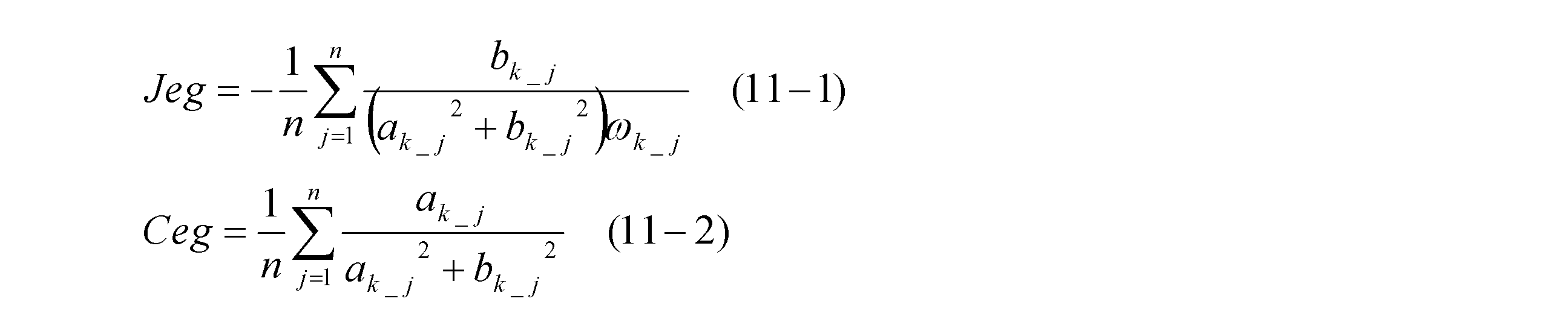
- the moment of inertia estimation step the n-number ( "n” is any integer of 2 or greater) K_j different measurement frequencies of omega ( “j" integer from 1 to n is), these measuring frequency It is preferable that the real part and the imaginary part of the ratio in ⁇ k_j are a k_j and b k_j, and the value of the moment of inertia Jeg of the specimen is calculated by the following estimation formula using these values.
- the measurement frequency is preferably lower than a resonance frequency of a mechanical system configured by connecting the specimen and the dynamometer with the connecting shaft.
- a specimen property estimation apparatus for example, a test system 1 described later
- a specimen for example, an engine E described later
- a connecting shaft for example, a connecting shaft S described later
- a dynamometer for example, a dynamometer D described later
- a shaft torque sensor for example, a shaft torque sensor 7 described later
- the shaft torque sensor from a torque current command to the dynamometer by oscillating the dynamometer by a rotational speed detection device (for example, a dynamo rotational speed sensor 8 or an engine rotational speed sensor C described later) for detecting the rotational speed.
- a rotational speed detection device for example, a dynamo rotational speed sensor 8 or an engine rotational speed sensor C described later
- a first transfer function measuring means (for example, an arithmetic unit 9 to be described later) that measures the first transfer function up to the output of the dynamometer
- a second transfer function measuring means (for example, an arithmetic unit 9 to be described later) for measuring a second transfer function from the torque current command to the output of the rotation speed detection device, and the second transfer function as the first transfer function
- a moment of inertia estimating means (for example, an arithmetic unit 9 to be described later) for calculating a value at a predetermined measurement frequency of the ratio obtained by dividing by the above and estimating the moment of inertia using the value of the ratio.
- the first transfer function from the torque current command to the output of the shaft torque sensor and the second transfer function from the torque current command to the output of the rotational speed detection device are measured, and these first, And the value at a predetermined measurement frequency of the ratio of the second transfer function is calculated, and the moment of inertia of the specimen is estimated using the value of this ratio.
- the ratio of the first transfer function to the second transfer function (G2 (s) / G1 (s)) is Assuming that the rotational friction is “Ceg”, the moment of inertia is “Jeg”, and the Laplace operator is “s”, it can be expressed by an approximate expression using the rotational friction and the moment of inertia as shown in the following equation (5). Therefore, by using the value at the measurement frequency of the above ratio, the value of the moment of inertia can be estimated with high accuracy in consideration of the existence of rotational friction.
- the first transfer function and the second transfer function show the influence of the inverter torque control response of the inverter that supplies power to the dynamometer according to the torque current command, respectively, but in the present invention, these ratios are used.
- the influence of the inverter torque control response only the rotational friction and the moment of inertia can be estimated as in the following equation (5).
- the value of the ratio of the two transfer functions only needs to be calculated, and there is no need to use nonlinear programming as in the invention of Patent Document 3, so that the value of the moment of inertia can be estimated in a short time.
- the moment of inertia is estimated by calculating the value of the moment of inertia by averaging the values calculated under n different measurement frequencies. Can be further improved.
- the rotational friction value is calculated by averaging the values calculated under n different measurement frequencies, thereby estimating the rotational friction estimation accuracy. Can be further improved.
- the estimation accuracy of the moment of inertia and the rotation loss can be further improved.
- the rotational speed detection device detects the rotational speed of the output shaft of the dynamometer
- the above expression (5) is an approximate expression that holds in a low frequency range. Therefore, in this case, by making the measurement frequency lower than the resonance frequency, it is possible to further improve the estimation accuracy of the moment of inertia and the rotational friction derived based on the approximate expression (5).
- FIG. 1 is a diagram showing a configuration of a test system 1 according to the present embodiment.
- the test system 1 includes an engine E as a specimen, a dynamometer D connected to the engine E via a substantially rod-like connecting shaft S, and an engine control device that controls the output of the engine E via a throttle actuator 2. 5, an inverter 3 that supplies power to the dynamometer D, a dynamometer control device 6 that controls the output of the dynamometer D via the inverter 3, and a torsional torque generated on the connecting shaft S (hereinafter referred to as “shaft torque”)
- a shaft torque sensor 7 for detecting the rotational speed of the output shaft of the dynamometer D hereinafter referred to as “dynamo rotational speed”
- an output shaft of the engine E for example, a crankshaft.
- a shaft Rukusensa 7 comprises an operational unit 9 for performing various calculations using the output of the dynamo speed sensor 8 and the engine speed sensor C.
- the test system 1 is also called a so-called engine bench system with the engine E as a test target.
- the durability of the engine E is controlled by controlling the torque and speed of the dynamometer D using the dynamometer control device 6 while controlling the throttle opening of the engine E using the engine control device 5.
- Tests to evaluate fuel consumption and exhaust purification performance are conducted.
- the engine E The configuration related to the estimation of the characteristics will be described in detail.
- the engine control device 5 starts the engine E at a predetermined timing or controls the output of the engine E via the throttle actuator 2 in a predetermined manner.
- the dynamometer control device 6 generates a torque current command signal for the dynamometer D in a manner determined according to the test.
- the inverter 3 supplies power to the dynamometer D based on the torque current command signal generated by the dynamometer control device 6, thereby generating torque corresponding to the command signal in the dynamometer D.
- the arithmetic unit 9 controls the output of the dynamometer D by using the dynamometer control device 6 according to the procedure described later with reference to FIG. 2, while the shaft torque detected by the shaft torque sensor 7 at this time, Data relating to at least one of the dynamo rotational speed detected by the rotational speed sensor 8 and the engine rotational speed detected by the engine rotational speed sensor C is acquired, and the output shaft of the engine E is used as the rotational axis by using the acquired data.
- the inertia moment and the rotational friction approximately proportional to the rotational speed are estimated.
- the concept of the estimation method of the present invention will be described before describing a specific procedure for estimating the moment of inertia and the rotational friction with reference to the flowchart of FIG.
- “Jeg” is the moment of inertia [kgm 2 ] with the output shaft of the engine as the rotation axis
- “Ceg” is the rotational friction [Nms / rad] with the output shaft of the engine as the rotation axis
- “Ksh” is the shaft torque rigidity [Nm / rad]
- “Jdy” is the moment of inertia with the output shaft of the dynamometer as the rotation axis
- “Teg” is the engine torque [Nm]
- “weg” is the engine The rotational speed [rad / s]
- “Tsh” is the shaft torque [Nm]
- “wdy” is the dynamo rotational speed [rad / s]
- “Kinv” is the torque control response coefficient of the inverter
- “Tdy” is a torque current command value [Nm] of the inverter.
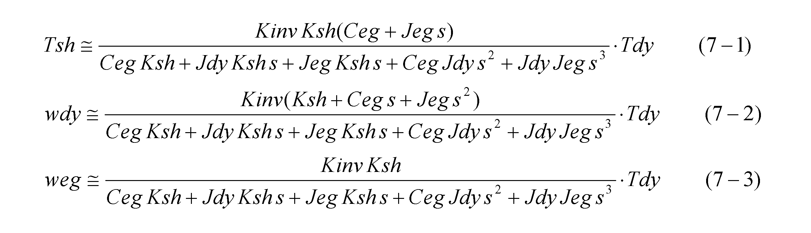
- the ratio between the torque current command value Tdy and the shaft torque Tsh is the first transfer function G1 (s)
- the ratio between the torque current command value Tdy and the dynamo rotational speed wdy is the second transfer function G2 (s).
- the ratio between the torque current command value Tdy and the engine speed weg is the third transfer function G3 (s)
- these first to third transfer functions are used to vibrate the dynamometer (that is, the torque current command value Tdy). Can be measured by acquiring the outputs of the shaft torque sensor, the dynamo rotation speed sensor, and the engine rotation speed sensor.
- the first to third transfer functions are proportional to the torque control response coefficient Kinv of the inverter, respectively. Therefore, when the second transfer function is divided by the first transfer function in order to cancel the influence of the torque control response coefficient Kinv, the following equation (8-1) is derived. Further, the low frequency characteristic of the equation (8-1) is as shown in the equation (8-2).
- the following formula (10) for the moment of inertia Jeg and the rotational friction Ceg is derived.
- the values of the right side coefficients a k and b k are specified by using the measurement result at the frequency ⁇ k . be able to. Therefore, using the measurement results of the first and second transfer functions, the moment of inertia Jeg and the rotational friction Ceg of the engine can be estimated by the following equations (10-1) and (10-2).
- FIG. 2 is a flowchart showing a procedure for estimating the characteristics of the engine using the ratio of the transfer function as shown in equations (8-2) and (12).
- the first transfer function G1 (s) from the torque current command value Tdy to the shaft torque Tsh is measured by oscillating the dynamometer under a predetermined excitation frequency.
- the second transfer function G2 (s) from the torque current command value Tdy to the dynamo rotational speed wdy (or engine rotational speed weg) (or by rotating the dynamometer at a predetermined excitation frequency) (or The third transfer function G3 (s)) is measured.
- the measurement frequency ⁇ k should be lower than the resonance frequency of a mechanical system configured by coupling the engine E and the dynamometer D with the shaft S. Is preferred.
- the equation (8-2) is an approximate equation that holds in a low frequency range, it is preferable that the measurement frequency ⁇ k is lower than the resonance frequency also from this viewpoint.
- the values of the engine inertia moment Jeg and the rotational friction Ceg may be calculated.
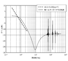
- FIG. 3 is a diagram showing a result when a conventional engine characteristic estimation method is applied to an engine having a known characteristic.
- the conventional engine characteristic estimation method specifically refers to a method described in Patent Document 1 (that is, Japanese Patent Application Laid-Open No. 2006-30068) by the present applicant.
- the true value of the moment of inertia of the engine used as a specimen is 0.19 [kgm 2 ], and the true value of the rotational friction of the engine is 0.64 [Nms / rad].
- FIG. 3 shows the result obtained by the conventional estimation method (more specifically, the moment of inertia EG.J obtained by the conventional estimation method is substituted into the above equation (8-2). Obtained results) are indicated by thick broken lines.
- the measurement result of the ratio between the second transfer function and the first transfer function that is, the transfer function from the output of the shaft torque sensor to the output of the dynamo rotation speed sensor
- a thin solid line for comparison with this, the measurement result of the ratio between the second transfer function and
- the conventional estimation method does not consider the rotational friction of the engine. For this reason, in the conventional estimation method, the low gain due to engine friction is regarded as being due to the increase of the moment of inertia. For this reason, the estimation result of the moment of inertia by the conventional estimation method is 0.25 [kgm 2 ], which is larger than the true value (0.19 [kgm 2 ]).
- FIG. 4 and 5 are diagrams showing results when the engine characteristic estimation method of the present invention is applied to the same known engine as that shown in FIG. More specifically, FIG. 4 shows the result when the moment of inertia Jeg and the rotational friction Ceg are estimated using the measurement result of the ratio of the second transfer function and the first transfer function, and FIG. 5 shows the third transfer function.
- the result at the time of estimating the moment of inertia Jeg and rotational friction Ceg using the measurement result of the ratio of a function and the 1st transfer function is shown.
- 4 and 5 indicate the results obtained by substituting the results obtained by the respective methods into the above equations (8-2) and (12).
- the thin solid line in FIG. 4 shows the measurement result of the ratio of the second transfer function to the first transfer function as in FIG. 3, and the thin solid line in FIG. 5 shows the ratio of the third transfer function to the first transfer function (that is, the axis
- the measurement result of the transfer function from the output of the torque sensor to the output of the engine speed sensor is
- the moment of inertia Jeg of the engine becomes 0.18 [kgm 2 ], which is obtained by the conventional estimation method of FIG. Compared with the result, a value sufficiently close to the true value was estimated.
- the rotational friction Ceg was also 0.66 [Nms / rad], and a value sufficiently close to the true value was estimated.
- the thick broken line and the thin solid line substantially coincide with each other in the low band. This means that the approximate expression (8-2) is sufficiently close to the measurement result in the low frequency range. Therefore, it can be said that the estimation method of the present invention can appropriately distinguish between the moment of inertia of the engine and the rotational friction.
- the inertia moment Jeg of the engine becomes 0.18 [kgm 2 ], and the rotational friction Ceg becomes 0.68 [Nms / rad]. Therefore, even when the ratio between the third transfer function and the first transfer function is used, the moment of inertia and the rotational friction can be estimated with sufficient accuracy. As described above, according to the present invention, the moment of inertia can be measured in a short time while considering the loss due to rotational friction.
- Test system (Specimen characteristic estimation device) 7 ... Shaft torque sensor 8 ... Dynamo rotation speed sensor (rotation speed detector) 9.
- Arithmetic unit (first transfer function measuring means, second transfer function measuring means, inertia moment estimating means) C ... Engine speed sensor (rotation speed detector) D ... Dynamometer E ... Engine (specimen) S ... Connecting shaft
Landscapes
- Physics & Mathematics (AREA)
- General Physics & Mathematics (AREA)
- Chemical & Material Sciences (AREA)
- Engineering & Computer Science (AREA)
- Combustion & Propulsion (AREA)
- Testing Of Engines (AREA)
Abstract
Description
試験システム100は、供試体であるエンジン160と軸170で連結されたダイナモメータ150と、エンジン160の出力を制御するスロットルアクチュエータ110及びエンジン制御装置120と、ダイナモメータ150の出力を制御するインバータ130及びダイナモメータ制御装置140とを備える。試験システム100では、エンジン制御装置120を用いてエンジン160のスロットル開度を制御しながら、ダイナモメータ制御装置140を用いてダイナモメータ150のトルクや速度を制御することにより、エンジン160の耐久性、燃費、及び排気浄化性能等が評価される。試験システム100では、上記のような性能を評価する試験を行う前にエンジン160の特性、とりわけエンジン160の慣性モーメントを測定しておき、これをダイナモメータ制御装置140におけるトルク制御や速度制御の制御パラメータとして利用する場合がある。





図1は、本実施形態に係る試験システム1の構成を示す図である。




より具体的には、図4は、第2伝達関数と第1伝達関数の比の測定結果を用いて慣性モーメントJeg及び回転摩擦Cegを推定した場合の結果を示し、図5は、第3伝達関数と第1伝達関数の比の測定結果を用いて慣性モーメントJeg及び回転摩擦Cegを推定した場合の結果を示す。また図4及び図5における太破線は、それぞれの方法で得られた結果を上記式(8-2)及び式(12)に代入して得られた結果示す。また図4における細実線は図3と同様に第2伝達関数と第1伝達関数の比の測定結果を示し、図5における細実線は第3伝達関数と第1伝達関数の比(すなわち、軸トルクセンサの出力からエンジン回転数センサの出力までの伝達関数)の測定結果を示す。
7…軸トルクセンサ
8…ダイナモ回転数センサ(回転数検出装置)
9…演算装置(第1伝達関数測定手段、第2伝達関数測定手段、慣性モーメント推定手段)
C…エンジン回転数センサ(回転数検出装置)
D…ダイナモメータ
E…エンジン(供試体)
S…連結軸
Claims (7)
- 供試体と連結軸を介して結合されたダイナモメータと、前記連結軸に発生する軸トルクを検出する軸トルクセンサと、前記供試体又は前記ダイナモメータの出力軸の回転数を検出する回転数検出装置と、を備えた試験システムを用いて、前記供試体の出力軸を回転軸とした慣性モーメントを推定する供試体特性推定方法であって、
前記ダイナモメータを加振運転することによって前記ダイナモメータに対するトルク電流指令から前記軸トルクセンサの出力までの第1伝達関数を測定する第1伝達関数測定工程と、
前記ダイナモメータを加振運転することによって前記トルク電流指令から前記回転数検出装置の出力までの第2伝達関数を測定する第2伝達関数測定工程と、
前記第2伝達関数を前記第1伝達関数で除算して得られる比の所定の測定周波数における値を算出し、当該比の値を用いて前記慣性モーメントを推定する慣性モーメント推定工程と、を備えることを特徴とする供試体特性推定方法。 - 前記慣性モーメント推定工程では、前記測定周波数をωkとし、当該測定周波数ωkにおける前記比の実部及び虚部をak及びbkとし、これらの値を用いて下記推定式によって前記供試体の慣性モーメントJegの値を算出することを特徴とする請求項1に記載の供試体特性推定方法。

- 前記測定周波数ωkにおける前記比の実部ak及び虚部bkの値を用いて、下記推定式によって前記供試体の出力軸を回転軸とした回転摩擦Cegの値を算出することを特徴とする請求項2に記載の供試体特性推定方法。

- 前記慣性モーメント推定工程では、n個(“n”は2以上の整数)の異なる測定周波数をωk_j(“j”は1からnの整数)とし、これら測定周波数ωk_jにおける前記比の実部及び虚部をak_j及びbk_jとし、これらの値を用いて下記推定式によって前記供試体の慣性モーメントJegの値を算出することを特徴とする請求項1に記載の供試体特性推定方法。

- 前記n個の異なる測定周波数ωk_jにおける前記比の実部ak_j及び虚部bk_jの値を用いて下記推定式によって前記供試体の出力軸を回転軸とした回転摩擦Cegの値を算出することを特徴とする請求項4に記載の供試体特性推定方法。

- 前記測定周波数は、前記供試体と前記ダイナモメータとを前記連結軸で結合して構成される機械系の共振周波数より低いことを特徴とする請求項1から5の何れかに記載の供試体特性推定方法。
- 供試体と連結軸を介して結合されたダイナモメータと、
前記連結軸に発生する軸トルクを検出する軸トルクセンサと、
前記供試体又は前記ダイナモメータの出力軸の回転数を検出する回転数検出装置と、を備え、前記供試体の出力軸を回転軸とした慣性モーメントを推定する供試体特性推定装置であって、
前記ダイナモメータを加振運転することによって前記ダイナモメータに対するトルク電流指令から前記軸トルクセンサの出力までの第1伝達関数を測定する第1伝達関数測定手段と、
前記ダイナモメータを加振運転することによって前記トルク電流指令から前記回転数検出装置の出力までの第2伝達関数を測定する第2伝達関数測定手段と、
前記第2伝達関数を前記第1伝達関数で除算して得られる比の所定の測定周波数における値を算出し、当該比の値を用いて前記慣性モーメントを推定する慣性モーメント推定手段と、を備えることを特徴とする供試体特性推定装置。
Priority Applications (2)
| Application Number | Priority Date | Filing Date | Title |
|---|---|---|---|
| KR1020187022455A KR102045801B1 (ko) | 2016-01-07 | 2016-12-13 | 공시체 특성 추정 방법 및 공시체 특성 추정 장치 |
| US16/068,484 US10605689B2 (en) | 2016-01-07 | 2016-12-13 | Test piece characteristic estimation method and test piece characteristic estimation device |
Applications Claiming Priority (2)
| Application Number | Priority Date | Filing Date | Title |
|---|---|---|---|
| JP2016-001626 | 2016-01-07 | ||
| JP2016001626A JP6149948B1 (ja) | 2016-01-07 | 2016-01-07 | 供試体特性推定方法及び供試体特性推定装置 |
Publications (1)
| Publication Number | Publication Date |
|---|---|
| WO2017119243A1 true WO2017119243A1 (ja) | 2017-07-13 |
Family
ID=59081905
Family Applications (1)
| Application Number | Title | Priority Date | Filing Date |
|---|---|---|---|
| PCT/JP2016/087057 Ceased WO2017119243A1 (ja) | 2016-01-07 | 2016-12-13 | 供試体特性推定方法及び供試体特性推定装置 |
Country Status (4)
| Country | Link |
|---|---|
| US (1) | US10605689B2 (ja) |
| JP (1) | JP6149948B1 (ja) |
| KR (1) | KR102045801B1 (ja) |
| WO (1) | WO2017119243A1 (ja) |
Cited By (1)
| Publication number | Priority date | Publication date | Assignee | Title |
|---|---|---|---|---|
| WO2019155728A1 (ja) * | 2018-02-08 | 2019-08-15 | 株式会社明電舎 | 試験システムの機械特性推定方法及び機械特性推定装置 |
Families Citing this family (8)
| Publication number | Priority date | Publication date | Assignee | Title |
|---|---|---|---|---|
| US10558179B2 (en) * | 2016-07-22 | 2020-02-11 | National University Corporation Chiba University | Shaft torque control device |
| CN107782498B (zh) * | 2017-10-10 | 2020-10-02 | 中国石油集团川庆钻探工程有限公司 | 测量柴油发动机当量转动惯量的系统及方法 |
| AT520554B1 (de) * | 2017-12-29 | 2019-05-15 | Avl List Gmbh | Prüfstand und Verfahren zum Durchführen eines dynamischen Prüflaufs für einen Prüfaufbau |
| AT520536B1 (de) * | 2017-12-29 | 2019-05-15 | Avl List Gmbh | Verfahren zum Schätzen eines inneren effektiven Drehmoments eines Drehmomentenerzeugers |
| JP6645525B2 (ja) * | 2018-02-23 | 2020-02-14 | 株式会社明電舎 | 試験システムの制御装置 |
| KR102256390B1 (ko) * | 2018-09-07 | 2021-05-26 | 메이덴샤 코포레이션 | 동력계 제어 장치 |
| JP7221770B2 (ja) * | 2019-04-08 | 2023-02-14 | 東洋電機製造株式会社 | 機械システムの摩擦同定装置 |
| CN113865846B (zh) * | 2021-09-26 | 2024-03-19 | 恪宁科技(上海)有限公司 | 一种血栓弹力图仪悬垂丝劲度系数检测装置及检测方法 |
Citations (4)
| Publication number | Priority date | Publication date | Assignee | Title |
|---|---|---|---|---|
| US5656768A (en) * | 1994-09-30 | 1997-08-12 | Avl Gesellschaft Fur Verbrennungskraftmaschinen Und Messtechnik M.B.H. Prof. Dr.H.C. Hans List | Method for determining the moment of inertia |
| JPH11194073A (ja) * | 1998-01-07 | 1999-07-21 | Meidensha Corp | 慣性モーメント同定方法 |
| JP2003294550A (ja) * | 2002-04-02 | 2003-10-15 | National Traffic Safety & Environment Laboratory | エンジン慣性測定方法 |
| JP2008076061A (ja) * | 2006-09-19 | 2008-04-03 | Meidensha Corp | エンジンベンチシステムのパラメータ推定装置 |
Family Cites Families (15)
| Publication number | Priority date | Publication date | Assignee | Title |
|---|---|---|---|---|
| JPH0384432A (ja) * | 1989-08-29 | 1991-04-10 | Ono Sokki Co Ltd | エンジン試験装置のダイナモ慣性補正によるエンジン出力軸トルク制御装置 |
| JP3800060B2 (ja) | 2001-10-10 | 2006-07-19 | 株式会社明電舎 | エンジンの慣性モーメント測定方法 |
| JP3772721B2 (ja) * | 2001-10-11 | 2006-05-10 | 株式会社明電舎 | エンジンベンチシステムおよびエンジン特性の測定方法 |
| JP4591176B2 (ja) | 2005-04-20 | 2010-12-01 | 株式会社明電舎 | エンジンの慣性モーメント測定装置 |
| JP4788627B2 (ja) | 2007-02-20 | 2011-10-05 | 株式会社明電舎 | エンジンベンチシステムのパラメータ推定装置 |
| WO2010013773A1 (ja) * | 2008-07-31 | 2010-02-04 | 株式会社フチノ | 原動機のトルク計測装置及びその方法、並びに制御プログラム |
| JP5605383B2 (ja) * | 2012-02-29 | 2014-10-15 | 株式会社明電舎 | ダイナモメータシステム |
| JP5947075B2 (ja) * | 2012-03-23 | 2016-07-06 | Dmg森精機株式会社 | 同期モータの制御装置、同期モータの制御方法 |
| ITMI20121483A1 (it) * | 2012-09-05 | 2014-03-06 | Angelo Morelli | Pedale automatico per biciclette |
| JP6020060B2 (ja) * | 2012-11-09 | 2016-11-02 | 株式会社ジェイテクト | 伝達トルク推定装置 |
| US9729094B2 (en) | 2013-06-10 | 2017-08-08 | Meidensha Corporation | Automatic suppression device for cyclic disturbance |
| JP5800001B2 (ja) * | 2013-10-07 | 2015-10-28 | 株式会社明電舎 | ダイナモメータシステム |
| JP6044647B2 (ja) * | 2015-01-13 | 2016-12-14 | 株式会社明電舎 | ダイナモメータの制御装置及びこれを用いた慣性モーメント推定方法 |
| JP6044649B2 (ja) * | 2015-01-19 | 2016-12-14 | 株式会社明電舎 | ダイナモメータシステムの制御装置 |
| JP6168126B2 (ja) * | 2015-11-09 | 2017-07-26 | 株式会社明電舎 | ダイナモメータシステムのダイナモ制御装置及びそのエンジン始動方法 |
-
2016
- 2016-01-07 JP JP2016001626A patent/JP6149948B1/ja active Active
- 2016-12-13 KR KR1020187022455A patent/KR102045801B1/ko active Active
- 2016-12-13 WO PCT/JP2016/087057 patent/WO2017119243A1/ja not_active Ceased
- 2016-12-13 US US16/068,484 patent/US10605689B2/en active Active
Patent Citations (4)
| Publication number | Priority date | Publication date | Assignee | Title |
|---|---|---|---|---|
| US5656768A (en) * | 1994-09-30 | 1997-08-12 | Avl Gesellschaft Fur Verbrennungskraftmaschinen Und Messtechnik M.B.H. Prof. Dr.H.C. Hans List | Method for determining the moment of inertia |
| JPH11194073A (ja) * | 1998-01-07 | 1999-07-21 | Meidensha Corp | 慣性モーメント同定方法 |
| JP2003294550A (ja) * | 2002-04-02 | 2003-10-15 | National Traffic Safety & Environment Laboratory | エンジン慣性測定方法 |
| JP2008076061A (ja) * | 2006-09-19 | 2008-04-03 | Meidensha Corp | エンジンベンチシステムのパラメータ推定装置 |
Cited By (3)
| Publication number | Priority date | Publication date | Assignee | Title |
|---|---|---|---|---|
| WO2019155728A1 (ja) * | 2018-02-08 | 2019-08-15 | 株式会社明電舎 | 試験システムの機械特性推定方法及び機械特性推定装置 |
| JP2019138723A (ja) * | 2018-02-08 | 2019-08-22 | 株式会社明電舎 | 試験システムの機械特性推定方法及び機械特性推定装置 |
| US11371912B2 (en) | 2018-02-08 | 2022-06-28 | Meidensha Corporation | Mechanical characteristics estimation method and mechanical characteristics estimation device of test system |
Also Published As
| Publication number | Publication date |
|---|---|
| KR20180091949A (ko) | 2018-08-16 |
| KR102045801B1 (ko) | 2019-11-18 |
| US10605689B2 (en) | 2020-03-31 |
| US20190017894A1 (en) | 2019-01-17 |
| JP2017122642A (ja) | 2017-07-13 |
| JP6149948B1 (ja) | 2017-06-21 |
Similar Documents
| Publication | Publication Date | Title |
|---|---|---|
| JP6149948B1 (ja) | 供試体特性推定方法及び供試体特性推定装置 | |
| JP6044647B2 (ja) | ダイナモメータの制御装置及びこれを用いた慣性モーメント推定方法 | |
| US10190944B2 (en) | Dynamometer-system dynamo control device and engine starting method therefor | |
| JP6044649B2 (ja) | ダイナモメータシステムの制御装置 | |
| JP5708704B2 (ja) | エンジンベンチシステム | |
| JP5316151B2 (ja) | 動力系の試験装置及びその制御方法 | |
| JP2021508059A (ja) | 試験構造のための動的な試験経過を実行する試験台及び方法 | |
| US11255749B2 (en) | Method and device for controlling a test stand arrangement | |
| JP4788627B2 (ja) | エンジンベンチシステムのパラメータ推定装置 | |
| JP6629574B2 (ja) | エンジン試験装置 | |
| US11313761B2 (en) | Test system | |
| JP4788543B2 (ja) | エンジンベンチシステムのパラメータ推定装置 | |
| JP4645231B2 (ja) | 動力伝達系の試験装置とその制御方法 | |
| JP4591176B2 (ja) | エンジンの慣性モーメント測定装置 | |
| JP4019709B2 (ja) | エンジンベンチシステム | |
| JP4655677B2 (ja) | 動力伝達系の試験装置とその制御方法 | |
| JP2010043940A (ja) | 動力伝達系の試験装置およびその制御方法 | |
| JP2003344224A (ja) | 動力伝達系の試験装置とその制御方法 | |
| JP3593732B2 (ja) | 自動車エンジン試験装置に使用する二慣性系パラメータ同定装置 | |
| JP5440619B2 (ja) | 供試体のパラメータ推定装置と機械共振周波数の検出方法 | |
| JP4639046B2 (ja) | 動力伝達系の試験装置とその制御方法 | |
| JP2009288036A (ja) | ローラ表面駆動力の推定方法とその装置 |
Legal Events
| Date | Code | Title | Description |
|---|---|---|---|
| 121 | Ep: the epo has been informed by wipo that ep was designated in this application |
Ref document number: 16883743 Country of ref document: EP Kind code of ref document: A1 |
|
| NENP | Non-entry into the national phase |
Ref country code: DE |
|
| ENP | Entry into the national phase |
Ref document number: 20187022455 Country of ref document: KR Kind code of ref document: A |
|
| WWE | Wipo information: entry into national phase |
Ref document number: 1020187022455 Country of ref document: KR |
|
| 122 | Ep: pct application non-entry in european phase |
Ref document number: 16883743 Country of ref document: EP Kind code of ref document: A1 |