WO2017110909A1 - 酸化物焼結体スパッタリングターゲット及びその製造方法 - Google Patents
酸化物焼結体スパッタリングターゲット及びその製造方法 Download PDFInfo
- Publication number
- WO2017110909A1 WO2017110909A1 PCT/JP2016/088182 JP2016088182W WO2017110909A1 WO 2017110909 A1 WO2017110909 A1 WO 2017110909A1 JP 2016088182 W JP2016088182 W JP 2016088182W WO 2017110909 A1 WO2017110909 A1 WO 2017110909A1
- Authority
- WO
- WIPO (PCT)
- Prior art keywords
- oxide
- sintered body
- sputtering target
- titanium
- less
- Prior art date
- Legal status (The legal status is an assumption and is not a legal conclusion. Google has not performed a legal analysis and makes no representation as to the accuracy of the status listed.)
- Ceased
Links
Images


Classifications
-
- C—CHEMISTRY; METALLURGY
- C23—COATING METALLIC MATERIAL; COATING MATERIAL WITH METALLIC MATERIAL; CHEMICAL SURFACE TREATMENT; DIFFUSION TREATMENT OF METALLIC MATERIAL; COATING BY VACUUM EVAPORATION, BY SPUTTERING, BY ION IMPLANTATION OR BY CHEMICAL VAPOUR DEPOSITION, IN GENERAL; INHIBITING CORROSION OF METALLIC MATERIAL OR INCRUSTATION IN GENERAL
- C23C—COATING METALLIC MATERIAL; COATING MATERIAL WITH METALLIC MATERIAL; SURFACE TREATMENT OF METALLIC MATERIAL BY DIFFUSION INTO THE SURFACE, BY CHEMICAL CONVERSION OR SUBSTITUTION; COATING BY VACUUM EVAPORATION, BY SPUTTERING, BY ION IMPLANTATION OR BY CHEMICAL VAPOUR DEPOSITION, IN GENERAL
- C23C14/00—Coating by vacuum evaporation, by sputtering or by ion implantation of the coating forming material
- C23C14/22—Coating by vacuum evaporation, by sputtering or by ion implantation of the coating forming material characterised by the process of coating
- C23C14/34—Sputtering
- C23C14/3407—Cathode assembly for sputtering apparatus, e.g. Target
- C23C14/3414—Metallurgical or chemical aspects of target preparation, e.g. casting, powder metallurgy
-
- C—CHEMISTRY; METALLURGY
- C23—COATING METALLIC MATERIAL; COATING MATERIAL WITH METALLIC MATERIAL; CHEMICAL SURFACE TREATMENT; DIFFUSION TREATMENT OF METALLIC MATERIAL; COATING BY VACUUM EVAPORATION, BY SPUTTERING, BY ION IMPLANTATION OR BY CHEMICAL VAPOUR DEPOSITION, IN GENERAL; INHIBITING CORROSION OF METALLIC MATERIAL OR INCRUSTATION IN GENERAL
- C23C—COATING METALLIC MATERIAL; COATING MATERIAL WITH METALLIC MATERIAL; SURFACE TREATMENT OF METALLIC MATERIAL BY DIFFUSION INTO THE SURFACE, BY CHEMICAL CONVERSION OR SUBSTITUTION; COATING BY VACUUM EVAPORATION, BY SPUTTERING, BY ION IMPLANTATION OR BY CHEMICAL VAPOUR DEPOSITION, IN GENERAL
- C23C14/00—Coating by vacuum evaporation, by sputtering or by ion implantation of the coating forming material
- C23C14/22—Coating by vacuum evaporation, by sputtering or by ion implantation of the coating forming material characterised by the process of coating
- C23C14/34—Sputtering
- C23C14/3407—Cathode assembly for sputtering apparatus, e.g. Target
-
- C—CHEMISTRY; METALLURGY
- C04—CEMENTS; CONCRETE; ARTIFICIAL STONE; CERAMICS; REFRACTORIES
- C04B—LIME, MAGNESIA; SLAG; CEMENTS; COMPOSITIONS THEREOF, e.g. MORTARS, CONCRETE OR LIKE BUILDING MATERIALS; ARTIFICIAL STONE; CERAMICS; REFRACTORIES; TREATMENT OF NATURAL STONE
- C04B35/00—Shaped ceramic products characterised by their composition; Ceramics compositions; Processing powders of inorganic compounds preparatory to the manufacturing of ceramic products
- C04B35/01—Shaped ceramic products characterised by their composition; Ceramics compositions; Processing powders of inorganic compounds preparatory to the manufacturing of ceramic products based on oxide ceramics
-
- C—CHEMISTRY; METALLURGY
- C04—CEMENTS; CONCRETE; ARTIFICIAL STONE; CERAMICS; REFRACTORIES
- C04B—LIME, MAGNESIA; SLAG; CEMENTS; COMPOSITIONS THEREOF, e.g. MORTARS, CONCRETE OR LIKE BUILDING MATERIALS; ARTIFICIAL STONE; CERAMICS; REFRACTORIES; TREATMENT OF NATURAL STONE
- C04B35/00—Shaped ceramic products characterised by their composition; Ceramics compositions; Processing powders of inorganic compounds preparatory to the manufacturing of ceramic products
- C04B35/01—Shaped ceramic products characterised by their composition; Ceramics compositions; Processing powders of inorganic compounds preparatory to the manufacturing of ceramic products based on oxide ceramics
- C04B35/453—Shaped ceramic products characterised by their composition; Ceramics compositions; Processing powders of inorganic compounds preparatory to the manufacturing of ceramic products based on oxide ceramics based on zinc, tin, or bismuth oxides or solid solutions thereof with other oxides, e.g. zincates, stannates or bismuthates
-
- C—CHEMISTRY; METALLURGY
- C04—CEMENTS; CONCRETE; ARTIFICIAL STONE; CERAMICS; REFRACTORIES
- C04B—LIME, MAGNESIA; SLAG; CEMENTS; COMPOSITIONS THEREOF, e.g. MORTARS, CONCRETE OR LIKE BUILDING MATERIALS; ARTIFICIAL STONE; CERAMICS; REFRACTORIES; TREATMENT OF NATURAL STONE
- C04B35/00—Shaped ceramic products characterised by their composition; Ceramics compositions; Processing powders of inorganic compounds preparatory to the manufacturing of ceramic products
- C04B35/622—Forming processes; Processing powders of inorganic compounds preparatory to the manufacturing of ceramic products
- C04B35/64—Burning or sintering processes
-
- C—CHEMISTRY; METALLURGY
- C23—COATING METALLIC MATERIAL; COATING MATERIAL WITH METALLIC MATERIAL; CHEMICAL SURFACE TREATMENT; DIFFUSION TREATMENT OF METALLIC MATERIAL; COATING BY VACUUM EVAPORATION, BY SPUTTERING, BY ION IMPLANTATION OR BY CHEMICAL VAPOUR DEPOSITION, IN GENERAL; INHIBITING CORROSION OF METALLIC MATERIAL OR INCRUSTATION IN GENERAL
- C23C—COATING METALLIC MATERIAL; COATING MATERIAL WITH METALLIC MATERIAL; SURFACE TREATMENT OF METALLIC MATERIAL BY DIFFUSION INTO THE SURFACE, BY CHEMICAL CONVERSION OR SUBSTITUTION; COATING BY VACUUM EVAPORATION, BY SPUTTERING, BY ION IMPLANTATION OR BY CHEMICAL VAPOUR DEPOSITION, IN GENERAL
- C23C14/00—Coating by vacuum evaporation, by sputtering or by ion implantation of the coating forming material
- C23C14/06—Coating by vacuum evaporation, by sputtering or by ion implantation of the coating forming material characterised by the coating material
- C23C14/08—Oxides
-
- C—CHEMISTRY; METALLURGY
- C23—COATING METALLIC MATERIAL; COATING MATERIAL WITH METALLIC MATERIAL; CHEMICAL SURFACE TREATMENT; DIFFUSION TREATMENT OF METALLIC MATERIAL; COATING BY VACUUM EVAPORATION, BY SPUTTERING, BY ION IMPLANTATION OR BY CHEMICAL VAPOUR DEPOSITION, IN GENERAL; INHIBITING CORROSION OF METALLIC MATERIAL OR INCRUSTATION IN GENERAL
- C23C—COATING METALLIC MATERIAL; COATING MATERIAL WITH METALLIC MATERIAL; SURFACE TREATMENT OF METALLIC MATERIAL BY DIFFUSION INTO THE SURFACE, BY CHEMICAL CONVERSION OR SUBSTITUTION; COATING BY VACUUM EVAPORATION, BY SPUTTERING, BY ION IMPLANTATION OR BY CHEMICAL VAPOUR DEPOSITION, IN GENERAL
- C23C14/00—Coating by vacuum evaporation, by sputtering or by ion implantation of the coating forming material
- C23C14/06—Coating by vacuum evaporation, by sputtering or by ion implantation of the coating forming material characterised by the coating material
- C23C14/08—Oxides
- C23C14/083—Oxides of refractory metals or yttrium
-
- C—CHEMISTRY; METALLURGY
- C23—COATING METALLIC MATERIAL; COATING MATERIAL WITH METALLIC MATERIAL; CHEMICAL SURFACE TREATMENT; DIFFUSION TREATMENT OF METALLIC MATERIAL; COATING BY VACUUM EVAPORATION, BY SPUTTERING, BY ION IMPLANTATION OR BY CHEMICAL VAPOUR DEPOSITION, IN GENERAL; INHIBITING CORROSION OF METALLIC MATERIAL OR INCRUSTATION IN GENERAL
- C23C—COATING METALLIC MATERIAL; COATING MATERIAL WITH METALLIC MATERIAL; SURFACE TREATMENT OF METALLIC MATERIAL BY DIFFUSION INTO THE SURFACE, BY CHEMICAL CONVERSION OR SUBSTITUTION; COATING BY VACUUM EVAPORATION, BY SPUTTERING, BY ION IMPLANTATION OR BY CHEMICAL VAPOUR DEPOSITION, IN GENERAL
- C23C14/00—Coating by vacuum evaporation, by sputtering or by ion implantation of the coating forming material
- C23C14/06—Coating by vacuum evaporation, by sputtering or by ion implantation of the coating forming material characterised by the coating material
- C23C14/08—Oxides
- C23C14/086—Oxides of zinc, germanium, cadmium, indium, tin, thallium or bismuth
-
- H—ELECTRICITY
- H01—ELECTRIC ELEMENTS
- H01J—ELECTRIC DISCHARGE TUBES OR DISCHARGE LAMPS
- H01J37/00—Discharge tubes with provision for introducing objects or material to be exposed to the discharge, e.g. for the purpose of examination or processing thereof
- H01J37/32—Gas-filled discharge tubes
- H01J37/34—Gas-filled discharge tubes operating with cathodic sputtering
- H01J37/3411—Constructional aspects of the reactor
- H01J37/3414—Targets
- H01J37/3426—Material
-
- C—CHEMISTRY; METALLURGY
- C04—CEMENTS; CONCRETE; ARTIFICIAL STONE; CERAMICS; REFRACTORIES
- C04B—LIME, MAGNESIA; SLAG; CEMENTS; COMPOSITIONS THEREOF, e.g. MORTARS, CONCRETE OR LIKE BUILDING MATERIALS; ARTIFICIAL STONE; CERAMICS; REFRACTORIES; TREATMENT OF NATURAL STONE
- C04B2235/00—Aspects relating to ceramic starting mixtures or sintered ceramic products
- C04B2235/02—Composition of constituents of the starting material or of secondary phases of the final product
- C04B2235/30—Constituents and secondary phases not being of a fibrous nature
- C04B2235/32—Metal oxides, mixed metal oxides, or oxide-forming salts thereof, e.g. carbonates, nitrates, (oxy)hydroxides, chlorides
- C04B2235/3231—Refractory metal oxides, their mixed metal oxides, or oxide-forming salts thereof
- C04B2235/3232—Titanium oxides or titanates, e.g. rutile or anatase
-
- C—CHEMISTRY; METALLURGY
- C04—CEMENTS; CONCRETE; ARTIFICIAL STONE; CERAMICS; REFRACTORIES
- C04B—LIME, MAGNESIA; SLAG; CEMENTS; COMPOSITIONS THEREOF, e.g. MORTARS, CONCRETE OR LIKE BUILDING MATERIALS; ARTIFICIAL STONE; CERAMICS; REFRACTORIES; TREATMENT OF NATURAL STONE
- C04B2235/00—Aspects relating to ceramic starting mixtures or sintered ceramic products
- C04B2235/02—Composition of constituents of the starting material or of secondary phases of the final product
- C04B2235/30—Constituents and secondary phases not being of a fibrous nature
- C04B2235/32—Metal oxides, mixed metal oxides, or oxide-forming salts thereof, e.g. carbonates, nitrates, (oxy)hydroxides, chlorides
- C04B2235/3231—Refractory metal oxides, their mixed metal oxides, or oxide-forming salts thereof
- C04B2235/3244—Zirconium oxides, zirconates, hafnium oxides, hafnates, or oxide-forming salts thereof
-
- C—CHEMISTRY; METALLURGY
- C04—CEMENTS; CONCRETE; ARTIFICIAL STONE; CERAMICS; REFRACTORIES
- C04B—LIME, MAGNESIA; SLAG; CEMENTS; COMPOSITIONS THEREOF, e.g. MORTARS, CONCRETE OR LIKE BUILDING MATERIALS; ARTIFICIAL STONE; CERAMICS; REFRACTORIES; TREATMENT OF NATURAL STONE
- C04B2235/00—Aspects relating to ceramic starting mixtures or sintered ceramic products
- C04B2235/02—Composition of constituents of the starting material or of secondary phases of the final product
- C04B2235/30—Constituents and secondary phases not being of a fibrous nature
- C04B2235/32—Metal oxides, mixed metal oxides, or oxide-forming salts thereof, e.g. carbonates, nitrates, (oxy)hydroxides, chlorides
- C04B2235/3284—Zinc oxides, zincates, cadmium oxides, cadmiates, mercury oxides, mercurates or oxide forming salts thereof
-
- C—CHEMISTRY; METALLURGY
- C04—CEMENTS; CONCRETE; ARTIFICIAL STONE; CERAMICS; REFRACTORIES
- C04B—LIME, MAGNESIA; SLAG; CEMENTS; COMPOSITIONS THEREOF, e.g. MORTARS, CONCRETE OR LIKE BUILDING MATERIALS; ARTIFICIAL STONE; CERAMICS; REFRACTORIES; TREATMENT OF NATURAL STONE
- C04B2235/00—Aspects relating to ceramic starting mixtures or sintered ceramic products
- C04B2235/02—Composition of constituents of the starting material or of secondary phases of the final product
- C04B2235/30—Constituents and secondary phases not being of a fibrous nature
- C04B2235/32—Metal oxides, mixed metal oxides, or oxide-forming salts thereof, e.g. carbonates, nitrates, (oxy)hydroxides, chlorides
- C04B2235/3286—Gallium oxides, gallates, indium oxides, indates, thallium oxides, thallates or oxide forming salts thereof, e.g. zinc gallate
-
- C—CHEMISTRY; METALLURGY
- C04—CEMENTS; CONCRETE; ARTIFICIAL STONE; CERAMICS; REFRACTORIES
- C04B—LIME, MAGNESIA; SLAG; CEMENTS; COMPOSITIONS THEREOF, e.g. MORTARS, CONCRETE OR LIKE BUILDING MATERIALS; ARTIFICIAL STONE; CERAMICS; REFRACTORIES; TREATMENT OF NATURAL STONE
- C04B2235/00—Aspects relating to ceramic starting mixtures or sintered ceramic products
- C04B2235/02—Composition of constituents of the starting material or of secondary phases of the final product
- C04B2235/50—Constituents or additives of the starting mixture chosen for their shape or used because of their shape or their physical appearance
- C04B2235/54—Particle size related information
- C04B2235/5418—Particle size related information expressed by the size of the particles or aggregates thereof
- C04B2235/5436—Particle size related information expressed by the size of the particles or aggregates thereof micrometer sized, i.e. from 1 to 100 micron
-
- C—CHEMISTRY; METALLURGY
- C04—CEMENTS; CONCRETE; ARTIFICIAL STONE; CERAMICS; REFRACTORIES
- C04B—LIME, MAGNESIA; SLAG; CEMENTS; COMPOSITIONS THEREOF, e.g. MORTARS, CONCRETE OR LIKE BUILDING MATERIALS; ARTIFICIAL STONE; CERAMICS; REFRACTORIES; TREATMENT OF NATURAL STONE
- C04B2235/00—Aspects relating to ceramic starting mixtures or sintered ceramic products
- C04B2235/65—Aspects relating to heat treatments of ceramic bodies such as green ceramics or pre-sintered ceramics, e.g. burning, sintering or melting processes
- C04B2235/656—Aspects relating to heat treatments of ceramic bodies such as green ceramics or pre-sintered ceramics, e.g. burning, sintering or melting processes characterised by specific heating conditions during heat treatment
-
- C—CHEMISTRY; METALLURGY
- C04—CEMENTS; CONCRETE; ARTIFICIAL STONE; CERAMICS; REFRACTORIES
- C04B—LIME, MAGNESIA; SLAG; CEMENTS; COMPOSITIONS THEREOF, e.g. MORTARS, CONCRETE OR LIKE BUILDING MATERIALS; ARTIFICIAL STONE; CERAMICS; REFRACTORIES; TREATMENT OF NATURAL STONE
- C04B2235/00—Aspects relating to ceramic starting mixtures or sintered ceramic products
- C04B2235/65—Aspects relating to heat treatments of ceramic bodies such as green ceramics or pre-sintered ceramics, e.g. burning, sintering or melting processes
- C04B2235/656—Aspects relating to heat treatments of ceramic bodies such as green ceramics or pre-sintered ceramics, e.g. burning, sintering or melting processes characterised by specific heating conditions during heat treatment
- C04B2235/6567—Treatment time
-
- C—CHEMISTRY; METALLURGY
- C04—CEMENTS; CONCRETE; ARTIFICIAL STONE; CERAMICS; REFRACTORIES
- C04B—LIME, MAGNESIA; SLAG; CEMENTS; COMPOSITIONS THEREOF, e.g. MORTARS, CONCRETE OR LIKE BUILDING MATERIALS; ARTIFICIAL STONE; CERAMICS; REFRACTORIES; TREATMENT OF NATURAL STONE
- C04B2235/00—Aspects relating to ceramic starting mixtures or sintered ceramic products
- C04B2235/70—Aspects relating to sintered or melt-casted ceramic products
- C04B2235/74—Physical characteristics
- C04B2235/77—Density
-
- C—CHEMISTRY; METALLURGY
- C04—CEMENTS; CONCRETE; ARTIFICIAL STONE; CERAMICS; REFRACTORIES
- C04B—LIME, MAGNESIA; SLAG; CEMENTS; COMPOSITIONS THEREOF, e.g. MORTARS, CONCRETE OR LIKE BUILDING MATERIALS; ARTIFICIAL STONE; CERAMICS; REFRACTORIES; TREATMENT OF NATURAL STONE
- C04B2235/00—Aspects relating to ceramic starting mixtures or sintered ceramic products
- C04B2235/70—Aspects relating to sintered or melt-casted ceramic products
- C04B2235/74—Physical characteristics
- C04B2235/78—Grain sizes and shapes, product microstructures, e.g. acicular grains, equiaxed grains, platelet-structures
- C04B2235/786—Micrometer sized grains, i.e. from 1 to 100 micron
-
- C—CHEMISTRY; METALLURGY
- C04—CEMENTS; CONCRETE; ARTIFICIAL STONE; CERAMICS; REFRACTORIES
- C04B—LIME, MAGNESIA; SLAG; CEMENTS; COMPOSITIONS THEREOF, e.g. MORTARS, CONCRETE OR LIKE BUILDING MATERIALS; ARTIFICIAL STONE; CERAMICS; REFRACTORIES; TREATMENT OF NATURAL STONE
- C04B2235/00—Aspects relating to ceramic starting mixtures or sintered ceramic products
- C04B2235/70—Aspects relating to sintered or melt-casted ceramic products
- C04B2235/80—Phases present in the sintered or melt-cast ceramic products other than the main phase
-
- C—CHEMISTRY; METALLURGY
- C04—CEMENTS; CONCRETE; ARTIFICIAL STONE; CERAMICS; REFRACTORIES
- C04B—LIME, MAGNESIA; SLAG; CEMENTS; COMPOSITIONS THEREOF, e.g. MORTARS, CONCRETE OR LIKE BUILDING MATERIALS; ARTIFICIAL STONE; CERAMICS; REFRACTORIES; TREATMENT OF NATURAL STONE
- C04B2235/00—Aspects relating to ceramic starting mixtures or sintered ceramic products
- C04B2235/70—Aspects relating to sintered or melt-casted ceramic products
- C04B2235/95—Products characterised by their size, e.g. microceramics
-
- C—CHEMISTRY; METALLURGY
- C04—CEMENTS; CONCRETE; ARTIFICIAL STONE; CERAMICS; REFRACTORIES
- C04B—LIME, MAGNESIA; SLAG; CEMENTS; COMPOSITIONS THEREOF, e.g. MORTARS, CONCRETE OR LIKE BUILDING MATERIALS; ARTIFICIAL STONE; CERAMICS; REFRACTORIES; TREATMENT OF NATURAL STONE
- C04B2235/00—Aspects relating to ceramic starting mixtures or sintered ceramic products
- C04B2235/70—Aspects relating to sintered or melt-casted ceramic products
- C04B2235/96—Properties of ceramic products, e.g. mechanical properties such as strength, toughness, wear resistance
Definitions
- the present invention relates to an oxide sintered sputtering target used for forming a metal oxide thin film and a method for producing the same.
- metal oxides such as ITO (Indium Tin Oxide), ZnO (Zinc Oxide), IZO (Indium Zinc Oxide), and IGZO (Indium Gallium Zinc Oxide) have been used as transparent electrode films for various displays, electronic components, semiconductor elements, etc. It is used in various fields.
- Patent Document 1 discloses a thin film transistor having a pixel electrode made of a transparent conductive oxide such as ITO, IZO, or ZnO.
- Patent Document 2 discloses a method of manufacturing a TFT array substrate having a metal oxide semiconductor film made of IGZO, IZO, ZnO, or the like.
- JP 2013-25307 A JP-T-2015-505168
- This type of metal oxide thin film is typically formed by sputtering using a target material composed of a sintered metal oxide.
- the film quality of the metal oxide thin film greatly depends on the quality of the sintered body constituting the sputtering target. For example, depending on the size of the pinhole present in the sintered body, nodules and abnormal discharge are likely to occur, and as a result, there is a problem that particles increase and yield decreases. For this reason, it has been necessary to increase the relative density of the sintered body by setting the firing temperature to a higher temperature, for example, and to suppress the generation of particles as much as possible.
- an object of the present invention is to provide an oxide sintered sputtering target capable of suppressing a decrease in mechanical strength and an increase in specific resistance, and a method for producing the same.
- an oxide sintered body sputtering target includes a sintered body containing indium oxide, zinc oxide, titanium oxide, and zirconium oxide.
- the atomic ratio of titanium to the total of titanium is 0.1% to 20%, and the weight ratio of zirconium to the total of indium oxide, zinc oxide, titanium oxide, and zirconium oxide is 10 ppm to 2000 ppm.
- Titanium oxide plays a role as an auxiliary agent for improving sinterability. Therefore, the relative density of the sintered body containing indium oxide, zinc oxide, titanium oxide and zirconium oxide is improved by setting the atomic ratio of titanium to the sum of indium, zinc and titanium to be 0.1% or more and 20% or less. However, stable direct current sputtering can be ensured by keeping the specific resistance of the sintered body low.
- the weight ratio of zirconium to the sum of indium oxide, zinc oxide, titanium oxide and zirconium oxide 10 ppm or more and 2000 ppm or less the grain growth (coarseness) of titanium oxide is suppressed, and the bending strength or The bending strength can be increased, and the occurrence of cracks and cracks can be suppressed.
- the weight ratio of zirconium to the sum of indium oxide, zinc oxide, titanium oxide, and zirconium oxide is 30 ppm to 1400 ppm, and the atomic ratio of zirconium to titanium is 0.6 or less.
- the sintered body typically has a relative density of 95% or more.
- the oxide constituting the sintered body may have an average crystal grain size of 15 ⁇ m or less and a specific resistance value of 0.1 m ⁇ ⁇ cm to 300 m ⁇ ⁇ cm.
- the sintered body may include an alloy phase or a compound phase of an In 2 O 3 phase and at least one of In—Ti—O, Zn—Ti—O, and In—Zn—O.
- the sintered body may include an In 2 O 3 phase having an average particle diameter of 15 ⁇ m or less.
- the pinhole included in the sintered body may have an equivalent circle diameter of 1 ⁇ m or less.
- a method of manufacturing an oxide sintered body sputtering target provides an indium oxide powder, a zinc oxide powder, a titanium oxide powder, and a zirconium oxide powder, When these powders are mixed, the atomic ratio of titanium to the sum of indium, zinc and titanium is 0.1% or more and 20% or less, and the weight ratio of zirconium to the sum of indium oxide, zinc oxide, titanium oxide and zirconium oxide is Producing a mixed powder of 10 ppm to 2000 ppm, The mixed powder is fired at a predetermined temperature.
- titanium oxide powder a raw material powder of titanium oxide having a rutile ratio of 80% or more and an average crystal grain size of 3 ⁇ m or less may be used.
- the predetermined temperature may be not less than 1240 ° C and not more than 1400 ° C.
- an oxide sintered body sputtering target capable of suppressing a decrease in mechanical strength and an increase in specific resistance.
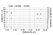
- FIG. 4 is a diagram showing a relationship between a Ti atomic ratio, specific resistance, bending strength, and relative density in an In—Zn—Ti—O sintered body according to an embodiment of the present invention.
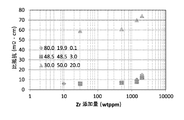
- FIG. 4 is a diagram showing a relationship between a Zr weight ratio and a specific resistance in the In—Zn—Ti—O sintered body.
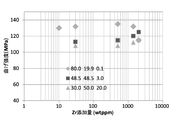
- FIG. 4 is a diagram showing a relationship between a Zr weight ratio and bending strength in the In—Zn—Ti—O sintered body.
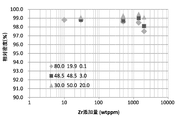
- FIG. 4 is a diagram showing a relationship between a Zr weight ratio and a relative density in the In—Zn—Ti—O sintered body.
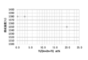
- FIG. 6 is a graph showing the Ti atomic ratio dependence of the firing temperature of the In—Zn—Ti—O sintered body having a relative density of 98.6% to 98.7%.
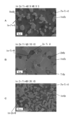
- 3 is an SEM image showing crystal structures of three systems of In—Zn—Ti—O sintered bodies having different composition ratios. It is a process flow explaining the manufacturing method of the oxide sintered compact sputtering target which concerns on one Embodiment of this invention. It is one experimental result which shows TMA of the sample powder which added two titanium oxide powders from which a rutile ratio differs in each powder of indium oxide, zinc oxide, and a zirconium oxide. It is a figure which shows the time change of TMA of FIG.
- An oxide sintered body sputtering target (hereinafter also simply referred to as a sputtering target) according to an embodiment of the present invention includes a sintered body (hereinafter referred to as indium oxide, zinc oxide, titanium oxide, and a small amount of zirconium oxide). In-Zn-Ti-O sintered body).
- the sputtering target is used as a film formation target such as an active layer of a thin film transistor, a transparent conductive film, a pixel electrode, or a transparent electrode of a solar power generation panel.
- the sputtering target of the present embodiment has a configuration in which IZO (indium zinc oxide) is the main composition, and Ti and Zr are respectively added in predetermined amounts.
- IZO indium zinc oxide
- the atomic ratio of Ti to the sum of In (indium), Zn (zinc) and Ti (titanium) (hereinafter also referred to as Ti atomic ratio) is 0.1% or more and 20% or less. It is. That is, the content of Ti in the total amount of In, Zn and Ti constituting the sintered body is 0.1 atomic% or more and 20 atomic% or less.
- Titanium oxide plays a role as an auxiliary agent for improving sinterability.
- the Ti atomic ratio is less than 0.1%, the relative density of the sintered body containing indium oxide, zinc oxide, titanium oxide and zirconium oxide is difficult to increase.
- the Ti atomic ratio exceeds 20%, the relative density of the sintered body is likely to increase, but precipitation of titanium oxide alone increases, and the specific resistance value of the sintered body increases extremely and is stable. It is difficult to ensure the direct current sputtering.
- FIG. 1 shows the relationship between the Ti atomic ratio, specific resistance, bending strength, and relative density in the In—Zn—Ti—O sintered body.
- the horizontal axis is Ti atomic ratio
- the left vertical axis is specific resistance (m ⁇ ⁇ cm) ( ⁇ plot)
- the right vertical axis is bending strength (MPa) ( ⁇ plot) and relative density (%) ( ⁇ Each plot).
- the Ti atomic ratio As shown in FIG. 1, by setting the Ti atomic ratio to 0.1% or more and 20% or less, a specific resistance of 10 m ⁇ ⁇ cm or less, a bending strength (bending strength) of approximately 125 MPa or more, and 95% or more. Relative density can be obtained. Further, in the sample having a Ti atomic ratio of 22%, the value of the specific resistance increases rapidly, so that control becomes difficult. From such a viewpoint, the Ti atomic ratio is preferably 20% or less.
- the weight ratio of Zr (zirconium) to the sum of indium oxide, zinc oxide, titanium oxide and zirconium oxide (hereinafter also referred to as Zr weight ratio) is 10 ppm or more and 2000 ppm or less. That is, the amount of metal Zr detected in the metal oxide constituting the sintered body is 10 ppm or more and 2000 ppm or less in terms of weight ratio.
- Zr weight ratio is less than 10 ppm, the effect of suppressing the grain growth of the titanium oxide is small, the Zr weight ratio is more than 2000 ppm, specific resistance because alone come to deposition of zirconium oxide (ZrO 2) is increased, When used for DC sputtering, abnormal discharge tends to occur.
- Zirconium oxide suppresses the grain growth of titanium oxide (TiO 2 ) and largely contributes to an increase in bending strength. Specifically, zirconium oxide (ZrO 2 ) precipitates at the crystal grain boundaries of the oxide and functions to hinder crystal growth (pinning effect). Thereby, since a sputtering target with dense crystal grains can be obtained, mechanical strength (bending strength) is improved, and generation of nodules and abnormal discharge is further suppressed.
- FIGS. 2 to 4 show the relationship between the Zr weight ratio, specific resistance, bending strength and relative density in the In—Zn—Ti—O sintered body, respectively.
- the horizontal axis represents the Zr weight ratio (Zr addition amount, wtppm), and the vertical axis represents the specific resistance (m ⁇ ⁇ cm), the bending strength (MPa), and the relative density (%), respectively.
- each plot of “ ⁇ ”, “ ⁇ ”, and “ ⁇ ” represents three types of sintered bodies having different Ti atomic ratios, and the ratio of In: Zn: Ti is 80: It corresponds to a sintered body of 19.9: 0.1, a sintered body of 48.5: 48.5: 3, and a sintered body of 30:50:20.
- the specific resistance tends to increase in all systems.
- the sintered bodies having a Ti atomic ratio of 0.1% and 3% have a very small specific resistance compared to a sintered body having a Ti atomic ratio of 20%, and are generally suppressed to 20 m ⁇ ⁇ cm or less. For this reason, stable discharge can be obtained not only by direct current sputtering but also by any sputtering method such as AC sputtering and RF sputtering.
- the bending strength tends to increase for the sintered bodies having the Ti atomic ratio of 3% and 20%, while the Ti atomic ratio is 0.1%.
- the bending strength of the sintered body tends to decrease.
- the relative density tends to start to decrease in all systems.
- the relative density reduction rate is relatively large.
- the Zr weight ratio in the In—Zn—Ti—O sintered body has a close correlation with the specific resistance, bending strength, and relative density of the sintered body. .
- the correlation with the Zr weight ratio is stronger than that of other sintered bodies, and the specific resistance and bending accompanying the increase in the Zr weight ratio.
- the change in strength and relative density is large.
- the atomic ratio of Ti and Zr in the sintered body is balanced with an increase in the Zr weight ratio, and Zr is excessive with respect to Ti.
- the zirconium oxide that precipitates at the grain boundaries of the oxide crystal becomes excessive, and conversely, cracking based on this tends to occur, and the mechanical strength of the sintered body decreases. it is conceivable that.
- the Zr weight ratio is limited so that the atomic ratio of Zr is equal to or less than the Ti atomic ratio of the sintered body, preferably 0.6 or less of the Ti atomic ratio, and further, the Zr weight ratio is set to 1400 ppm or less. This makes it possible to simultaneously suppress an increase in specific resistance and a decrease in bending strength and relative density.
- the minimum of Zr weight ratio can be 10 ppm or more, Preferably, it can be 30 ppm or more.
- the oxide constituting the sintered body typically has an average crystal grain size of 15 ⁇ m or less and a specific resistance value of 0.1 m ⁇ ⁇ cm to 300 m ⁇ ⁇ cm.
- the average crystal grain size of the oxide sintered body is suppressed to 15 ⁇ m or less, thereby improving the bending strength while suppressing an increase in specific resistance. can do. Further, since the specific resistance is suppressed to 300 m ⁇ ⁇ cm or less, direct current sputtering of the sputtering target made of the oxide sintered body becomes possible. In order to ensure more stable sputter discharge, the specific resistance of the oxide sintered body is preferably 80 m ⁇ ⁇ cm or less.
- FIG. 5 shows the experimental results showing the Ti atomic ratio dependence of the firing temperature of an In—Zn—Ti—O sintered body having a relative density of 98.6% to 98.7%.
- the firing temperature tends to decrease as the Ti atomic ratio increases. Thereby, it is possible to suppress the growth of crystal grains accompanying the increase in the firing temperature.
- the firing temperature can be lowered, there is an advantage that in the target manufacturing process, stress hardly remains in the target during cooling after firing.
- 6A to 6C are SEM images showing crystal structures of three systems of In—Zn—Ti—O sintered bodies having different composition ratios.
- white portions are phases mainly composed of In 2 O 3 phase, and the surroundings are In—Zn—O phase, In—Ti—O phase, and Zn—Ti—O phase.
- it is considered to be a single layer of ZnO 2 phase, or two or more alloy phases or compound phases thereof.
- the average grain size of the crystals constituting each of these phases was 15 ⁇ m or less.
- the quadrature method (JIS H0501) was used for the measurement of the average particle diameter of the crystal
- This method is a method of calculating the average grain size of crystal grains using an electron microscope. Specifically, a crystal grain photograph is taken with an electron microscope, and a rectangle of about 5000 mm 2 is drawn on the photograph. The sum of the number of crystal grains completely contained in this area and the half of the number of crystal grains cut around the rectangle is defined as the total crystal grains, and the average crystal grain size is calculated by the following formula.
- d is the average crystal grain size
- M is the use magnification
- A is the measurement area
- z is the number of crystal grains completely contained in A
- w is the number of crystal grains in the peripheral portion
- n is the total number of crystal grains.
- the black dots recognized in the SEM images of FIGS. 6A to 6C are presumed to be pinholes included in the sintered body.
- the equivalent circle diameter was 1 ⁇ m or less.
- the Ti atomic ratio is 0.1% or more and 20% or less
- the Zr weight ratio is Since it is composed of 10 ppm or more and 2000 ppm or less, a sputtering target having a high density (95% or more), a low specific resistance (300 m ⁇ ⁇ cm or less), and a high bending strength can be obtained.
- stable DC sputtering can be ensured and cracks and cracks can be suppressed, so that abnormal discharge and nodules that occur during sputtering discharge can be suppressed, and handling of the sputtering target Can be improved.
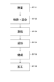
- FIG. 7 is a process flow illustrating a method for manufacturing an oxide sintered body sputtering target according to an embodiment of the present invention.
- the manufacturing method of the present embodiment includes a weighing process (step 101), a pulverization / mixing process (step 102), a granulation process (step 103), a molding process (step 104), and a firing process (step 105). And a processing step (step 106).
- indium oxide powder, zinc oxide powder, titanium oxide powder, and zirconium oxide powder are prepared.
- the average particle size of the powder (including the compound powder) used as a raw material for the oxide sintered body is preferably 5 ⁇ m or less.
- the titanium oxide powder As the titanium oxide powder, a titanium oxide powder having a relatively high rutile ratio is used. When TiO 2 raw materials with the same average particle diameter of raw materials and different rutile rates are used, the shrinkage proceeds more when the rutile rate is higher from the result of TMA (thermomechanical analysis) indicating the amount of shrinkage. As will be described later, the relative density of the obtained sintered body is higher than when the rutile ratio is low.
- a titanium oxide raw material powder having a rutile ratio of 80% or more and an average crystal grain size of 3 ⁇ m or less is used as the titanium oxide powder.
- Ti atomic ratio 0.1% or more and 20% or less
- indium oxide, zinc oxide, titanium oxide and zirconium oxide A mixed powder having a zirconium weight ratio (Zr weight ratio) of 10 ppm to 2000 ppm is prepared.
- a wet mixing method using a ball mill device can be used for mixing raw material powders.
- a bead mill device, a starburst device, a V-type mixer, a tumbler mixer, and the like can be applied, and a good oxide sintered body can be obtained also by these.
- a wet mixing method using an apparatus having the capability of simultaneously dispersing and crushing (pulverizing) the raw material powder.
- a slurry may be produced and pulverized (pulverized) using a bead mill method, a starburst method, or the like.
- the raw material powder produced by the dry mixing method is more likely to aggregate and bias the raw material powder than the wet mixing method.
- the raw material powder is agglomerated or biased, a difference in sintering speed occurs during sintering of the raw material powder, and a desired sintered body may not be obtained.
- problems such as density, resistance value, crystal structure, crystal grains, and the like of the sintered body are more likely to occur due to the aggregation and unevenness of the raw material powder than in the wet mixing method.
- the raw material powder is mixed and pulverized (pulverized) at the same time by a wet mixing method, but a ceramic medium may be used for pulverizing (pulverizing) the raw material powder.
- a ceramic medium may be used for pulverizing (pulverizing) the raw material powder.
- Most preferred is ZrO 2 media.
- the raw material powder can be mixed and pulverized (disintegrated) in a short time.
- the amount of Zr added to the raw material powder using the medium made of ZrO 2 is about 10 to 10000 ppm by weight, and the wet mixing time at that time is in the range of 5 to 100 hr, preferably 5 to The range is 80 hours.
- the amount of zirconium oxide powder mixed may be adjusted in consideration of the amount of ZrO 2 mixed in the raw material powder at the time of pulverization (pulverization) of the raw material powder using a ZrO 2 medium.
- the Zr weight ratio of the sintered body may be adjusted with ZrO 2 mixed from the medium without using powder.
- “preparation of zirconium oxide powder” includes not only the preparation of zirconium oxide powder but also the pulverization (pulverization) of the raw material powder using a ZrO 2 medium.
- a binder is added to the raw material that has been mixed and pulverized (pulverized) by a wet mixing method, followed by solid-liquid separation, drying, and granulation.
- the amount of binder added is preferably in the range of 0.5 to 3.0 wt%.
- limiting in particular about solid-liquid separation, drying, and granulation of the raw material powder after wet mixing For example, well-known manufacturing methods, such as spray-drying with a spray dryer apparatus, are employable.
- the obtained granulated powder is filled into a rubber or metal mold and molded by applying a pressure of 1.0 ton / cm 2 or more with a cold isostatic press (CIP). Do. It is also possible to obtain an oxide sintered body by hot pressing such as a hot press as a known production method, but in consideration of the manufacturing cost and the enlargement of the oxide sintered body, cold pressure forming Is better.
- CIP cold isostatic press
- the degreasing of the molded body is preferably performed in an air atmosphere or an oxygen atmosphere (an atmosphere having an oxygen concentration higher than the air). At that time, the furnace atmosphere is preferably always fresh.
- the degreasing temperature is appropriately set from the range of 450 ° C. to 800 ° C. depending on the kind of the added binder.
- the compact is sintered in either an air atmosphere or an oxygen atmosphere (an atmosphere having an oxygen concentration higher than the air), and the sintering temperature is in the range of 800 to 1600 ° C. If it is 800 ° C. or lower, the sintering does not proceed and the density becomes poor, and if it is 1600 ° C. or higher, the raw material powder may evaporate.
- the sintering temperature is preferably 1240 ° C. or higher and 1400 ° C. or lower.
- the rate of temperature rise from room temperature is preferably 0.1 ° C./min to 5.0 ° C./min, whereby an oxide sintered body having a high density and a uniform crystal structure with a relative density of 95% or more can be obtained. .
- the holding time of the sintering temperature may be set as appropriate depending on the shape and weight of the molded body in the range of 2 hr to 20 hr. If the holding time is shorter than the time required for the weight of the compact, the oxide sintered body will have a poor density, but if the holding time is long, the crystal grains become coarse, the pores become coarse, It becomes a factor such as a decrease in strength of the body.
- the relative density is higher than that of using the titanium oxide raw material powder having a rutile ratio of less than 80%.
- the temperature rise rate can be increased.
- the titanium oxide powder when a material having a low rutile ratio is selected for the titanium oxide powder, it is necessary to perform heating slowly between temperatures at which anatase undergoes phase transition to rutile (600 to 1000 ° C.). This is because if the temperature rising rate is set high (for example, 1 ° C./min or more), the surface layer of the sintered body is rutiled first to form a shell due to a phase transition from anatase to rutile during the sintering process, and a fire is caused. This is because the inside of the body is hindered from shrinking when sintered and the density is hardly increased. Furthermore, cracks are likely to occur in the surface layer of the sintered body, and pinholes are likely to occur inside the sintered body.
- FIG. 8 shows a raw material powder containing indium oxide powder, zinc oxide powder and zirconium oxide powder, titanium oxide powder having a rutile ratio of 80% or more (89.2%), and a rutile ratio of less than 80% (73. It is one experimental result which shows the evaluation result of TMA (Thermomechanical analysis) of the powder sample which added 2%) titanium oxide powder.
- FIG. 9 shows the time differential value ( ⁇ TMA) of the experimental result obtained in FIG. In the experiment, the dimensional change in the height direction of the sample was measured when the sample was formed by compacting the powder into a rod shape and heated with a static constant load applied.
- a raw material powder of titanium oxide having an average crystal grain size of 3 ⁇ m or less is used as the titanium oxide powder. Since the raw material powder having a small average crystal grain size has a relatively large specific surface area, the surface energy is high and it is easy to sinter. That is, since the sinterability is enhanced, a high-density sintered body can be produced in a relatively short time.
- the sintered body manufactured as described above is machined into a plate shape having a desired shape, size, and thickness, so that a sputtering target made of an In—Zn—Ti—O sintered body is manufactured. .
- the sputtering target is integrated with a backing plate (not shown) by brazing.
- Example 1 An In—Zn—Ti—O sintered body having an In: Zn: Ti ratio of 80.0: 19.9: 0.1 and a Zr weight ratio of 10 ppm was formed into a shape having a length of 170 mm, a width of 170 mm, and a thickness of 11 mm. Further, it was produced under firing conditions of 1380 ° C. for 8 hours. When the specific resistance, bending strength, and relative density of the obtained sintered body were measured, they were 6 m ⁇ ⁇ cm, 130 MPa, and 98.8%, respectively. In addition, regarding the measurement of bending strength, the sample cut out into the dimension of length 40mm, width 4mm, and thickness 3mm from the sintered compact produced by the above-mentioned dimension was used.
- Example 2 A sintered body was produced under the same conditions as Sample 1 except that the Zr weight ratio was 30 ppm. When the specific resistance, bending strength, and relative density of the obtained sintered body were measured, they were 6 m ⁇ ⁇ cm, 132 MPa, and 98.8%, respectively.
- Example 3 A sintered body was produced under the same conditions as Sample 1 except that the Zr weight ratio was 500 ppm. When the specific resistance, bending strength, and relative density of the obtained sintered body were measured, they were 7 m ⁇ ⁇ cm, 135 MPa, and 98.6%, respectively.
- Example 4 A sintered body was produced under the same conditions as Sample 1 except that the Zr weight ratio was 1400 ppm. When the specific resistance, bending strength, and relative density of the obtained sintered body were measured, they were 10 m ⁇ ⁇ cm, 132 MPa, and 98.5%, respectively.
- Example 5 A sintered body was produced under the same conditions as Sample 1 except that the Zr weight ratio was 2000 ppm. When the specific resistance, bending strength, and relative density of the obtained sintered body were measured, they were 15 m ⁇ ⁇ cm, 115 MPa, and 97.5%, respectively.
- Example 6 A sintered body was produced under the same conditions as Sample 1 except that the ratio of In: Zn: Ti was 48.5: 48.5: 3.0 and the Zr weight ratio was 30 ppm. When the specific resistance, bending strength, and relative density of the obtained sintered body were measured, they were 6 m ⁇ ⁇ cm, 113 MPa, and 98.8%, respectively.
- Example 7 A sintered body was produced under the same conditions as Sample 6 except that the Zr weight ratio was 500 ppm. When the specific resistance, bending strength, and relative density of the obtained sintered body were measured, they were 7 m ⁇ ⁇ cm, 115 MPa, and 98.7%, respectively.
- Example 8 A sintered body was produced under the same conditions as Sample 6 except that the Zr weight ratio was 1400 ppm. When the specific resistance, bending strength, and relative density of the obtained sintered body were measured, they were 8 m ⁇ ⁇ cm, 120 MPa, and 90.0%, respectively.
- Example 9 A sintered body was produced under the same conditions as Sample 6 except that the Zr weight ratio was 2000 ppm. When the specific resistance, bending strength, and relative density of the obtained sintered body were measured, they were 12 m ⁇ ⁇ cm, 125 MPa, and 98.1%, respectively.
- Example 10 A sintered body was produced under the same conditions as Sample 1 except that the In: Zn: Ti ratio was 30.0: 50.0: 20.0 and the Zr weight ratio was 30 ppm. When the specific resistance, bending strength, and relative density of the obtained sintered body were measured, they were 59 m ⁇ ⁇ cm, 108 MPa, and 99.1%, respectively.
- Example 11 A sintered body was produced under the same conditions as Sample 10 except that the Zr weight ratio was 500 ppm. When the specific resistance, bending strength, and relative density of the obtained sintered body were measured, they were 61 m ⁇ ⁇ cm, 108 MPa, and 99.3%, respectively.
- Example 12 A sintered body was produced under the same conditions as Sample 6 except that the Zr weight ratio was 1400 ppm. When the specific resistance, bending strength, and relative density of the obtained sintered body were measured, they were 70 m ⁇ ⁇ cm, 112 MPa, and 99.5%, respectively.
- Example 13 A sintered body was produced under the same conditions as Sample 6 except that the Zr weight ratio was 2000 ppm. When the specific resistance, bending strength, and relative density of the obtained sintered body were measured, they were 74 m ⁇ ⁇ cm, 115 MPa, and 99.1%, respectively.
- Example 14 A sintered body was produced under the same conditions as Sample 1, except that the In: Zn: Ti ratio was 70.0: 29.9: 0.1, the Zr weight ratio was 500 ppm, and the firing time was 4 hours. When the specific resistance, bending strength, and relative density of the obtained sintered body were measured, they were 5 m ⁇ ⁇ cm, 130 MPa, and 98.6%, respectively.
- Example 15 A sintered body was produced under the same conditions as Sample 1 except that the In: Zn: Ti ratio was 70.0: 27.0: 3.0, the Zr weight ratio was 500 ppm, and the firing time was 4 hours.
- the specific resistance, bending strength, and relative density of the obtained sintered body were measured, they were 2 m ⁇ ⁇ cm, 125 MPa, and 98.7%, respectively.
- Example 16 Baking was performed under the same conditions as Sample 1, except that the ratio of In: Zn: Ti was 70.0: 10.0: 20.0, the weight ratio of Zr was 500 ppm, the baking temperature was 1350 ° C., and the baking time was 4 hours. A ligature was prepared. When the specific resistance, bending strength and relative density of the obtained sintered body were measured, 10 m ⁇ ⁇ cm, 120 MPa, and 98.7%.
- Example 17 Bake under the same conditions as Sample 1 except that the In: Zn: Ti ratio is 70.0: 8.0: 22.0, the Zr weight ratio is 500 ppm, the firing temperature is 1330 ° C., and the firing time is 4 hours.
- a ligature was prepared. When the specific resistance, bending strength, and relative density of the obtained sintered body were measured, they were 100 m ⁇ ⁇ cm, 120 MPa, and 98.7%, respectively.
- Table 1 summarizes the compositions, evaluation results, and firing conditions of Samples 1 to 19.
- values of 15 m ⁇ ⁇ cm or less are obtained for samples 1 to 9 and samples 14 to 16. This value is the same as the specific resistance value (about 20 m ⁇ ⁇ cm) of a typical IGZO as a metal oxide, and stable discharge can be maintained when direct current sputtering is performed.
- the specific resistance values of samples 10 to 13 and sample 17 exceed 50 m ⁇ ⁇ cm, but various conditions (atmosphere temperature, gas type to be introduced, etc.) for direct current sputtering are controlled. By doing so, it is within a range in which the occurrence of abnormal discharge and nodules can be suppressed.
- the specific resistance value is a relatively large result of 100 m ⁇ ⁇ cm.
- the Zr weight ratio of the sample 17 is 500 ppm, and the Zr weight ratio in the Ti atomic ratio of the sample 17 is 2000 ppm taking into account the tendency that the specific resistance value increases as the Zr weight ratio increases as seen in the samples 1 to 16. It is expected that the specific resistance value exceeds 300 m ⁇ ⁇ cm. In this case, discharge by direct current sputtering becomes difficult. Therefore, when the Ti atomic ratio is large, a significant increase in the specific resistance value may be prevented by limiting the Zr weight ratio. That is, even if the Ti atomic ratio exceeds 20% as in Sample 17, the specific resistance value of the obtained sintered body is suppressed to about 100 m ⁇ ⁇ cm by limiting the Zr weight ratio to 500 ppm or less. Can do.
Landscapes
- Chemical & Material Sciences (AREA)
- Engineering & Computer Science (AREA)
- Organic Chemistry (AREA)
- Materials Engineering (AREA)
- Ceramic Engineering (AREA)
- Manufacturing & Machinery (AREA)
- Mechanical Engineering (AREA)
- Chemical Kinetics & Catalysis (AREA)
- Metallurgy (AREA)
- Structural Engineering (AREA)
- Physics & Mathematics (AREA)
- Plasma & Fusion (AREA)
- Analytical Chemistry (AREA)
- Inorganic Chemistry (AREA)
- Physical Vapour Deposition (AREA)
- Compositions Of Oxide Ceramics (AREA)
Abstract
Description
一方、酸化インジウム、酸化亜鉛、酸化チタンおよび酸化ジルコニウムの総和に対するジルコニウムの重量比を10ppm以上2000ppm以下とすることにより、酸化チタンの粒成長(粗大化)を抑制し、焼結体の曲げ強度あるいは抗折強度を高めて、割れやクラックの発生を抑えることができる。
これらの粉末を混合し、インジウム、亜鉛およびチタンの総和に対するチタンの原子比が0.1%以上20%以下であり、酸化インジウム、酸化亜鉛、酸化チタンおよび酸化ジルコニウムの総和に対するジルコニウムの重量比が10ppm以上2000ppm以下である混合粉末を作製し、
前記混合粉末を所定温度で焼成する。
本発明の一実施形態に係る酸化物焼結体スパッタリングターゲット(以下、単にスパッタリングターゲットともいう)は、酸化インジウムと、酸化亜鉛と、酸化チタンと、微量の酸化ジルコニウムとを含む焼結体(以下、In-Zn-Ti-O焼結体ともいう)で構成される。スパッタリングターゲットは、例えば、薄膜トランジスタの活性層や透明導電膜、画素電極、太陽発電パネルの透明電極などの成膜用ターゲットとして用いられる。
d=(1/M)√(A/n) …(1)
n=z+(w/2) …(2)
ここで、dは平均結晶粒径、Mは使用倍率、Aは測定面積、zはA内に完全に含まれる結晶粒数、wは周辺部の結晶粒数、nは全結晶粒数である。
次に、本実施形態のスパッタリングターゲットの典型的な製造方法について説明する。
本実施形態の製造方法は、秤量工程(ステップ101)と、粉砕・混合工程(ステップ102)と、造粒工程(ステップ103)と、成形工程(ステップ104)と、焼成工程(ステップ105)と、加工工程(ステップ106)とを有する。
原料粉末として、酸化インジウム粉末と、酸化亜鉛粉末と、酸化チタン粉末と、酸化ジルコニウム粉末とを準備する。酸化物焼結体の原料として用いられる粉末(化合物粉末を含む)の平均粒径は、それぞれ5μm以下が望ましい。
続いて、湿式混合法により混合、粉砕(解砕)が完了した原料にバインダを0.1~5.0wt%添加し固液分離、乾燥、造粒を行う。バインダの添加量は0.5~3.0wt%の範囲が好ましい。また、湿式混合後の原料粉末の固液分離、乾燥及び顆粒化については特に制限はなく、例えばスプレードライヤ装置で噴霧乾燥するなどの公知の製法が採用可能である。
次に、得られた造粒粉末をゴム製もしくは金属製の型枠に充填し、冷間静水圧等方加圧装置(CIP)にて1.0ton/cm2以上の圧力をかけて成形を行う。他にも公知の製法としてホットプレスなど温間で加圧し酸化物焼結体を得ることも可能だが、製造にかかるコストや酸化物焼結体の大型化を考慮すると冷間での加圧成形の方がよい。
成形体の焼結は大気雰囲気、酸素雰囲気(大気より酸素濃度が高い雰囲気)のいずれかで行い、焼結温度は800~1600℃の範囲で行われる。800℃以下では焼結が進まず、密度不良となり、1600℃以上では原料粉末が蒸発してしまうおそれがある。
以上にようにして作製された焼結体は、所望の形状、大きさ、厚みの板形状に機械加工されることで、In-Zn-Ti-O焼結体からなるスパッタリングターゲットが作製される。当該スパッタリングターゲットは、図示しないバッキングプレートへロウ接により一体化される。
続いて、本発明者らが行った実験例について説明する。以下の実験例は、Ti原子比およびZr重量比が異なる複数のIn-Zn-Ti-O焼結体を作製し、それらの比抵抗、曲げ強度、相対密度を測定した。比抵抗は、公知の4端子法を用いた測定値とし、曲げ強度は、JIS R1601に準拠した3点曲げ試験での測定値とした。相対密度は、焼結体の見掛け密度と理論密度との比を計算により求めた。
In:Zn:Tiの比が80.0:19.9:0.1であり、Zr重量比が10ppmのIn-Zn-Ti-O焼結体を、縦170mm、横170mm、厚み11mmの形状に、1380℃、8時間の焼成条件で作製した。得られた焼結体の比抵抗、曲げ強度および相対密度を測定したところ、それぞれ、6mΩ・cm、130MPa、98.8%であった。
なお、曲げ強度の測定に関しては、上述の寸法で作製した焼結体から、縦40mm、横4mm、厚み3mmの寸法に切り出したサンプルを用いた。
Zr重量比を30ppmとした以外は、サンプル1と同様の条件で焼結体を作製した。得られた焼結体の比抵抗、曲げ強度および相対密度を測定したところ、それぞれ、6mΩ・cm、132MPa、98.8%であった。
Zr重量比を500ppmとした以外は、サンプル1と同様の条件で焼結体を作製した。得られた焼結体の比抵抗、曲げ強度および相対密度を測定したところ、それぞれ、7mΩ・cm、135MPa、98.6%であった。
Zr重量比を1400ppmとした以外は、サンプル1と同様の条件で焼結体を作製した。得られた焼結体の比抵抗、曲げ強度および相対密度を測定したところ、それぞれ、10mΩ・cm、132MPa、98.5%であった。
Zr重量比を2000ppmとした以外は、サンプル1と同様の条件で焼結体を作製した。得られた焼結体の比抵抗、曲げ強度および相対密度を測定したところ、それぞれ、15mΩ・cm、115MPa、97.5%であった。
In:Zn:Tiの比を48.5:48.5:3.0、Zr重量比を30ppmとした以外は、サンプル1と同様の条件で焼結体を作製した。得られた焼結体の比抵抗、曲げ強度および相対密度を測定したところ、それぞれ、6mΩ・cm、113MPa、98.8%であった。
Zr重量比を500ppmとした以外は、サンプル6と同様の条件で焼結体を作製した。得られた焼結体の比抵抗、曲げ強度および相対密度を測定したところ、それぞれ、7mΩ・cm、115MPa、98.7%であった。
Zr重量比を1400ppmとした以外は、サンプル6と同様の条件で焼結体を作製した。得られた焼結体の比抵抗、曲げ強度および相対密度を測定したところ、それぞれ、8mΩ・cm、120MPa、90.0%であった。
Zr重量比を2000ppmとした以外は、サンプル6と同様の条件で焼結体を作製した。得られた焼結体の比抵抗、曲げ強度および相対密度を測定したところ、それぞれ、12mΩ・cm、125MPa、98.1%であった。
In:Zn:Tiの比を30.0:50.0:20.0、Zr重量比を30ppmとした以外は、サンプル1と同様の条件で焼結体を作製した。得られた焼結体の比抵抗、曲げ強度および相対密度を測定したところ、それぞれ、59mΩ・cm、108MPa、99.1%であった。
Zr重量比を500ppmとした以外は、サンプル10と同様の条件で焼結体を作製した。得られた焼結体の比抵抗、曲げ強度および相対密度を測定したところ、それぞれ、61mΩ・cm、108MPa、99.3%であった。
Zr重量比を1400ppmとした以外は、サンプル6と同様の条件で焼結体を作製した。得られた焼結体の比抵抗、曲げ強度および相対密度を測定したところ、それぞれ、70mΩ・cm、112MPa、99.5%であった。
Zr重量比を2000ppmとした以外は、サンプル6と同様の条件で焼結体を作製した。得られた焼結体の比抵抗、曲げ強度および相対密度を測定したところ、それぞれ、74mΩ・cm、115MPa、99.1%であった。
In:Zn:Tiの比を70.0:29.9:0.1、Zr重量比を500ppm、焼成時間を4時間とした以外は、サンプル1と同様の条件で焼結体を作製した。得られた焼結体の比抵抗、曲げ強度および相対密度を測定したところ、それぞれ、5mΩ・cm、130MPa、98.6%であった。
In:Zn:Tiの比を70.0:27.0:3.0、Zr重量比を500ppm、焼成時間を4時間とした以外は、サンプル1と同様の条件で焼結体を作製した。得られた焼結体の比抵抗、曲げ強度および相対密度を測定したところ、それぞれ、2mΩ・cm、125MPa、98.7%であった。
In:Zn:Tiの比を70.0:10.0:20.0、Zr重量比を500ppm、焼成温度を1350℃、焼成時間を4時間とした以外は、サンプル1と同様の条件で焼結体を作製した。得られた焼結体の比抵抗、曲げ強度および相対密度を測定したところ、それぞれ、
10mΩ・cm、120MPa、98.7%であった。
In:Zn:Tiの比を70.0:8.0:22.0、Zr重量比を500ppm、焼成温度を1330℃、焼成時間を4時間とした以外は、サンプル1と同様の条件で焼結体を作製した。得られた焼結体の比抵抗、曲げ強度および相対密度を測定したところ、それぞれ、100mΩ・cm、120MPa、98.7%であった。

なお、Ti原子比が22%であるサンプル17に関しては、比抵抗が100mΩ・cmと比較的高かった。また、Ti原子比が高くなるほど、曲げ強度が低下する傾向にあることが確認された(図1参照)。
Claims (10)
- 酸化インジウムと、酸化亜鉛と、酸化チタンと、酸化ジルコニウムとを含む焼結体で構成され、
インジウム、亜鉛およびチタンの総和に対するチタンの原子比は、0.1%以上20%以下であり、
酸化インジウム、酸化亜鉛、酸化チタンおよび酸化ジルコニウムの総和に対するジルコニウムの重量比は、10ppm以上2000ppm以下である
酸化物焼結体スパッタリングターゲット。 - 請求項1に記載の酸化物焼結体スパッタリングターゲットであって、
酸化インジウム、酸化亜鉛、酸化チタンおよび酸化ジルコニウムの総和に対するジルコニウムの重量比は、30ppm以上1400ppm以下であり、
チタンに対するジルコニウムの原子比は、0.6以下である
酸化物焼結体スパッタリングターゲット。 - 請求項1又は2に記載の酸化物焼結体スパッタリングターゲットであって、
前記焼結体は、95%以上の相対密度を有する
酸化物焼結体スパッタリングターゲット。 - 請求項1~3のいずれか1つに記載の酸化物焼結体スパッタリングターゲットであって、
前記焼結体を構成する酸化物は、15μm以下の平均結晶粒径と、0.1mΩ・cm以上300mΩ・cm以下の比抵抗値とを有する
酸化物焼結体スパッタリングターゲット。 - 請求項1~4のいずれか1つに記載の酸化物焼結体スパッタリングターゲットであって、
前記焼結体は、In2O3相と、In-Ti-O、Zn-Ti-O及びIn-Zn-Oの少なくとも1つの相との合金相あるいは化合物相を含む
酸化物焼結体スパッタリングターゲット。 - 請求項1~5のいずれか1つに記載の酸化物焼結体スパッタリングターゲットであって、
前記焼結体は、15μm以下の平均粒径を有するIn2O3相を含む
酸化物焼結体スパッタリングターゲット。 - 請求項1~6のいずれか1つに記載の酸化物焼結体スパッタリングターゲットであって、
前記焼結体が含むピンホールは、円相当径で1μm以下である
酸化物焼結体スパッタリングターゲット。 - 酸化インジウム粉末と、酸化亜鉛粉末と、酸化チタン粉末と、酸化ジルコニウム粉末とを準備し、
これらの粉末を混合し、インジウム、亜鉛およびチタンの総和に対するチタンの原子比が0.1%以上20%以下であり、酸化インジウム、酸化亜鉛、酸化チタンおよび酸化ジルコニウムの総和に対するジルコニウムの重量比が10ppm以上2000ppm以下である混合粉末を作製し、
前記混合粉末を所定温度で焼成する
酸化物焼結体スパッタリングターゲットの製造方法。 - 請求項8に記載の酸化物焼結体スパッタリングターゲットの製造方法であって、
前記酸化チタン粉末として、ルチル化率が80%以上であり、平均結晶粒径が3μm以下である酸化チタンの原料粉末を用いる
酸化物焼結体スパッタリングターゲットの製造方法。 - 請求項8又は9に記載の酸化物焼結体スパッタリングターゲットの製造方法であって、
前記所定温度は、1240℃以上1400℃以下である
酸化物焼結体スパッタリングターゲットの製造方法。
Priority Applications (4)
| Application Number | Priority Date | Filing Date | Title |
|---|---|---|---|
| CN201680063587.8A CN108350564B (zh) | 2015-12-25 | 2016-12-21 | 氧化物烧结体溅射靶及其制造方法 |
| US15/778,086 US20180355472A1 (en) | 2015-12-25 | 2016-12-21 | Oxide-sintered-body sputtering target and method of producing the same |
| JP2017558206A JP6646686B2 (ja) | 2015-12-25 | 2016-12-21 | 酸化物焼結体スパッタリングターゲット及びその製造方法 |
| KR1020187011437A KR20180056746A (ko) | 2015-12-25 | 2016-12-21 | 산화물 소결체 스퍼터링 타겟 및 그 제조 방법 |
Applications Claiming Priority (2)
| Application Number | Priority Date | Filing Date | Title |
|---|---|---|---|
| JP2015-252902 | 2015-12-25 | ||
| JP2015252902 | 2015-12-25 |
Publications (1)
| Publication Number | Publication Date |
|---|---|
| WO2017110909A1 true WO2017110909A1 (ja) | 2017-06-29 |
Family
ID=59089493
Family Applications (1)
| Application Number | Title | Priority Date | Filing Date |
|---|---|---|---|
| PCT/JP2016/088182 Ceased WO2017110909A1 (ja) | 2015-12-25 | 2016-12-21 | 酸化物焼結体スパッタリングターゲット及びその製造方法 |
Country Status (6)
| Country | Link |
|---|---|
| US (1) | US20180355472A1 (ja) |
| JP (1) | JP6646686B2 (ja) |
| KR (1) | KR20180056746A (ja) |
| CN (1) | CN108350564B (ja) |
| TW (1) | TWI655166B (ja) |
| WO (1) | WO2017110909A1 (ja) |
Cited By (2)
| Publication number | Priority date | Publication date | Assignee | Title |
|---|---|---|---|---|
| WO2019027153A1 (ko) * | 2017-08-03 | 2019-02-07 | 주식회사 나노신소재 | 복합 산화물 소결체 및 스퍼터링 타겟, 산화물 투명도전막의 제조방법 |
| CN118771879A (zh) * | 2024-07-31 | 2024-10-15 | 郑州大学 | 具有高迁移率的氧化铟锡锌靶材及其制备方法 |
Families Citing this family (4)
| Publication number | Priority date | Publication date | Assignee | Title |
|---|---|---|---|---|
| KR20220087425A (ko) * | 2019-10-23 | 2022-06-24 | 미쓰비시 마테리알 가부시키가이샤 | 산화물 스퍼터링 타깃 |
| TWI719820B (zh) * | 2020-01-31 | 2021-02-21 | 光洋應用材料科技股份有限公司 | 銦鋯氧化物靶材及其製法及銦鋯氧化物薄膜 |
| TWI819633B (zh) * | 2022-05-31 | 2023-10-21 | 光洋應用材料科技股份有限公司 | 氧化銦鈦鋅濺鍍靶材、其薄膜及其製法 |
| CN116199496B (zh) * | 2022-12-15 | 2024-07-19 | 先导薄膜材料(广东)有限公司 | 一种氧化铟锌掺杂稀土金属靶材及其制备方法 |
Citations (4)
| Publication number | Priority date | Publication date | Assignee | Title |
|---|---|---|---|---|
| JPH11256321A (ja) * | 1998-03-13 | 1999-09-21 | Sumitomo Metal Mining Co Ltd | ZnO系焼結体 |
| JP2006206384A (ja) * | 2005-01-28 | 2006-08-10 | Tdk Corp | 非可逆回路素子用セラミック材料及びその製造方法 |
| WO2012077512A1 (ja) * | 2010-12-06 | 2012-06-14 | 東ソー株式会社 | 酸化亜鉛焼結体、スパッタリングターゲット及び酸化亜鉛薄膜 |
| WO2015059938A1 (ja) * | 2013-10-24 | 2015-04-30 | Jx日鉱日石金属株式会社 | 酸化物焼結体、酸化物スパッタリングターゲット及び高屈折率の導電性酸化物薄膜並びに酸化物焼結体の製造方法 |
-
2016
- 2016-12-21 US US15/778,086 patent/US20180355472A1/en not_active Abandoned
- 2016-12-21 JP JP2017558206A patent/JP6646686B2/ja active Active
- 2016-12-21 WO PCT/JP2016/088182 patent/WO2017110909A1/ja not_active Ceased
- 2016-12-21 CN CN201680063587.8A patent/CN108350564B/zh active Active
- 2016-12-21 KR KR1020187011437A patent/KR20180056746A/ko not_active Ceased
- 2016-12-23 TW TW105142994A patent/TWI655166B/zh active
Patent Citations (4)
| Publication number | Priority date | Publication date | Assignee | Title |
|---|---|---|---|---|
| JPH11256321A (ja) * | 1998-03-13 | 1999-09-21 | Sumitomo Metal Mining Co Ltd | ZnO系焼結体 |
| JP2006206384A (ja) * | 2005-01-28 | 2006-08-10 | Tdk Corp | 非可逆回路素子用セラミック材料及びその製造方法 |
| WO2012077512A1 (ja) * | 2010-12-06 | 2012-06-14 | 東ソー株式会社 | 酸化亜鉛焼結体、スパッタリングターゲット及び酸化亜鉛薄膜 |
| WO2015059938A1 (ja) * | 2013-10-24 | 2015-04-30 | Jx日鉱日石金属株式会社 | 酸化物焼結体、酸化物スパッタリングターゲット及び高屈折率の導電性酸化物薄膜並びに酸化物焼結体の製造方法 |
Cited By (4)
| Publication number | Priority date | Publication date | Assignee | Title |
|---|---|---|---|---|
| WO2019027153A1 (ko) * | 2017-08-03 | 2019-02-07 | 주식회사 나노신소재 | 복합 산화물 소결체 및 스퍼터링 타겟, 산화물 투명도전막의 제조방법 |
| KR20190014684A (ko) * | 2017-08-03 | 2019-02-13 | 주식회사 나노신소재 | 복합 산화물 소결체 및 스퍼터링 타겟, 산화물 투명도전막의 제조방법 |
| KR101999894B1 (ko) * | 2017-08-03 | 2019-07-12 | 주식회사 나노신소재 | 복합 산화물 소결체 및 스퍼터링 타겟, 산화물 투명도전막의 제조방법 |
| CN118771879A (zh) * | 2024-07-31 | 2024-10-15 | 郑州大学 | 具有高迁移率的氧化铟锡锌靶材及其制备方法 |
Also Published As
| Publication number | Publication date |
|---|---|
| KR20180056746A (ko) | 2018-05-29 |
| CN108350564A (zh) | 2018-07-31 |
| TWI655166B (zh) | 2019-04-01 |
| CN108350564B (zh) | 2020-05-15 |
| JPWO2017110909A1 (ja) | 2018-08-30 |
| TW201736316A (zh) | 2017-10-16 |
| US20180355472A1 (en) | 2018-12-13 |
| JP6646686B2 (ja) | 2020-02-14 |
Similar Documents
| Publication | Publication Date | Title |
|---|---|---|
| JP6646686B2 (ja) | 酸化物焼結体スパッタリングターゲット及びその製造方法 | |
| TWI433823B (zh) | 複合氧化物燒結體、複合氧化物燒結體之製造方法、濺鍍靶材及薄膜之製造方法 | |
| JP6291593B2 (ja) | Itoスパッタリングターゲット及びその製造方法並びにito透明導電膜の製造方法 | |
| JP5764828B2 (ja) | 酸化物焼結体およびそれを加工したタブレット | |
| CN103249693B (zh) | 氧化锌烧结体、溅射靶材以及氧化锌薄膜 | |
| TWI644866B (zh) | Izo燒結體濺鍍靶及其製造方法 | |
| WO2014021334A1 (ja) | 酸化物焼結体、及びスパッタリングターゲット | |
| KR20130018321A (ko) | 산화아연 소결체 타블렛 및 그의 제조 방법 | |
| TWI778100B (zh) | 氧化物燒結體及濺鍍靶 | |
| TWI575094B (zh) | In-Ce-O系濺鍍靶材及其製造方法 | |
| JP7158102B2 (ja) | Itoスパッタリングターゲット及びその製造方法並びにito透明導電膜及びito透明導電膜の製造方法 | |
| JP6677058B2 (ja) | Sn−Zn−O系酸化物焼結体とその製造方法 | |
| JP5727130B2 (ja) | 複合酸化物焼結体及びその用途 | |
| JP5720726B2 (ja) | 酸化亜鉛焼結体およびその製造方法 | |
| TW201736318A (zh) | 氧化物燒結體、其製造方法及濺鍍靶材 | |
| JP6637948B2 (ja) | Izoターゲット及びその製造方法 | |
| JP5967016B2 (ja) | 蒸着用タブレットとその製造方法 | |
| JP2014043598A (ja) | InZnO系スパッタリングターゲットの製造方法 | |
| WO2017149882A1 (ja) | Sn-Zn-O系酸化物焼結体とその製造方法 | |
| TW202124745A (zh) | 氧化物濺射靶及氧化物濺射靶的製造方法 | |
| JPH08246139A (ja) | 酸化物焼結体 | |
| TW202126838A (zh) | 氧化物濺射靶及氧化物濺射靶的製造方法 | |
| JP2016223012A (ja) | スパッタリングターゲット | |
| WO2021112006A1 (ja) | 酸化物スパッタリングターゲット、及び、酸化物スパッタリングターゲットの製造方法 | |
| TW202547817A (zh) | 含In、Ga、Zn、O之燒結體及其製造方法 |
Legal Events
| Date | Code | Title | Description |
|---|---|---|---|
| 121 | Ep: the epo has been informed by wipo that ep was designated in this application |
Ref document number: 16878796 Country of ref document: EP Kind code of ref document: A1 |
|
| ENP | Entry into the national phase |
Ref document number: 2017558206 Country of ref document: JP Kind code of ref document: A |
|
| ENP | Entry into the national phase |
Ref document number: 20187011437 Country of ref document: KR Kind code of ref document: A |
|
| NENP | Non-entry into the national phase |
Ref country code: DE |
|
| 122 | Ep: pct application non-entry in european phase |
Ref document number: 16878796 Country of ref document: EP Kind code of ref document: A1 |