WO2017110852A1 - 脱落防止具 - Google Patents
脱落防止具 Download PDFInfo
- Publication number
- WO2017110852A1 WO2017110852A1 PCT/JP2016/088054 JP2016088054W WO2017110852A1 WO 2017110852 A1 WO2017110852 A1 WO 2017110852A1 JP 2016088054 W JP2016088054 W JP 2016088054W WO 2017110852 A1 WO2017110852 A1 WO 2017110852A1
- Authority
- WO
- WIPO (PCT)
- Prior art keywords
- coil spring
- spring portion
- coil
- winding
- region
- Prior art date
- Legal status (The legal status is an assumption and is not a legal conclusion. Google has not performed a legal analysis and makes no representation as to the accuracy of the status listed.)
- Ceased
Links
Images


Classifications
-
- F—MECHANICAL ENGINEERING; LIGHTING; HEATING; WEAPONS; BLASTING
- F16—ENGINEERING ELEMENTS AND UNITS; GENERAL MEASURES FOR PRODUCING AND MAINTAINING EFFECTIVE FUNCTIONING OF MACHINES OR INSTALLATIONS; THERMAL INSULATION IN GENERAL
- F16B—DEVICES FOR FASTENING OR SECURING CONSTRUCTIONAL ELEMENTS OR MACHINE PARTS TOGETHER, e.g. NAILS, BOLTS, CIRCLIPS, CLAMPS, CLIPS OR WEDGES; JOINTS OR JOINTING
- F16B39/00—Locking of screws, bolts or nuts
- F16B39/02—Locking of screws, bolts or nuts in which the locking takes place after screwing down
- F16B39/20—Locking of screws, bolts or nuts in which the locking takes place after screwing down by means of steel wire or the like
-
- F—MECHANICAL ENGINEERING; LIGHTING; HEATING; WEAPONS; BLASTING
- F16—ENGINEERING ELEMENTS AND UNITS; GENERAL MEASURES FOR PRODUCING AND MAINTAINING EFFECTIVE FUNCTIONING OF MACHINES OR INSTALLATIONS; THERMAL INSULATION IN GENERAL
- F16B—DEVICES FOR FASTENING OR SECURING CONSTRUCTIONAL ELEMENTS OR MACHINE PARTS TOGETHER, e.g. NAILS, BOLTS, CIRCLIPS, CLAMPS, CLIPS OR WEDGES; JOINTS OR JOINTING
- F16B39/00—Locking of screws, bolts or nuts
- F16B39/22—Locking of screws, bolts or nuts in which the locking takes place during screwing down or tightening
- F16B39/28—Locking of screws, bolts or nuts in which the locking takes place during screwing down or tightening by special members on, or shape of, the nut or bolt
- F16B39/34—Locking by deformable inserts or like parts
-
- F—MECHANICAL ENGINEERING; LIGHTING; HEATING; WEAPONS; BLASTING
- F16—ENGINEERING ELEMENTS AND UNITS; GENERAL MEASURES FOR PRODUCING AND MAINTAINING EFFECTIVE FUNCTIONING OF MACHINES OR INSTALLATIONS; THERMAL INSULATION IN GENERAL
- F16B—DEVICES FOR FASTENING OR SECURING CONSTRUCTIONAL ELEMENTS OR MACHINE PARTS TOGETHER, e.g. NAILS, BOLTS, CIRCLIPS, CLAMPS, CLIPS OR WEDGES; JOINTS OR JOINTING
- F16B41/00—Measures against loss of bolts, nuts, or pins; Measures against unauthorised operation of bolts, nuts or pins
Definitions
- the present invention relates to a drop-off prevention device. Specifically, the present invention relates to a drop-off prevention tool that prevents the fixed object and nut from falling off the bolt.
- a method for fixing two members constituting a building structure a method of fixing by welding or a method of fastening by bolts and nuts is used.
- fixing by welding requires welding equipment, and it takes time and labor for construction. Also, equipment is required for releasing the fixing, and it takes time and effort to release the fixing. Many methods are adopted.
- Patent Literature 1 describes a nut 401 with a locking function as shown in FIG. That is, the nut 401 with a locking function described in Patent Document 1 includes a locking tool 403 and a hex nut 102.
- the loosening stop 403 includes a loosening coil portion 103A around which a metal wire is wound with substantially the same diameter, and the outer edge of the hexagon nut 102 that extends outward in a tangential direction from the lower end of the loosening coil portion 103A. And an automatic tightening adjustment unit 410 composed of a drawn metal wire.
- the loose fastener 403 is bent downward from the upper end of the loose coil portion 103A, is an annular narrow groove, and is a nut that can be engaged with the loose fastener engaging portion 430 formed on the upper surface of the hexagon nut 102.
- An engaging portion 420 is provided.
- the nut engaging part 420 is comprised by the part 103B wound larger than the diameter of the loosening coil part 103A, and the part 103C engaged with the hexagon nut 102.
- Patent Document 1 has an automatic tightening adjustment portion as a straight portion, the automatic tightening adjustment portion is not configured to be fitted into the screw groove of the bolt. There was a problem that it was difficult to attach the tool to the bolt.
- the present invention has been made in view of the above points, and an object thereof is to provide a drop-off preventing tool that can be easily attached to a bolt.
- the drop-off prevention device of the present invention includes a coil spring portion in which a coil wire is wound in a substantially circular shape with substantially the same diameter, and one end of the coil wire constituting the coil spring portion.
- the extending extension coil wire has a winding range larger than the winding range of the coil spring portion, is concentric with the coil spring portion, and a plurality of top portions are substantially the same distance from the winding center of the coil spring portion.
- the tip of the extended coil wire that is wound in a polygonal shape that is a shape arranged in a straight line extending in a tangential direction of the coil spring portion and that is separated from one end of the coil wire And a projecting portion having an end region disposed on the side away from the coil spring portion in the same direction as the direction in which the winding center of the coil spring portion extends.
- the coil element wire can be fitted to the leg portion of the bolt by the coil spring portion wound in a substantially circular shape with the substantially same diameter.
- the extension coil wire extending from one end of the coil wire constituting the coil spring portion is in a winding range larger than the winding range of the coil spring portion, concentric with the coil spring portion, and a plurality of top portions are coil spring portions. At least one of the extended coil strands by an overhanging portion that is wound in a polygonal shape, which is a shape that is disposed at substantially the same distance from the winding center of the wire, and that extends substantially linearly in the tangential direction of the coil spring portion. Three straight portions can be fitted into the screw grooves of the bolt.
- the end region disposed on the side away from the coil spring portion in the same direction as the direction in which the winding center of the coil spring portion extends is a region within a predetermined range from the tip of the extension coil strand separated from one end of the coil wire. Since the overhanging portion is not formed so as to surround the coil spring portion, it is easy to fit at least three straight portions of the extension coil wire into the screw groove of the bolt.
- the end region disposed on the side away from the coil spring portion in the same direction as the direction in which the winding center of the coil spring portion extends is a region within a predetermined range from the tip of the extension coil strand separated from one end of the coil wire.
- the end region can be curved outside the winding range of the coil spring portion and protruding into the winding range of the overhang portion.
- the end region pressed against the nut is pushed outside the winding range of the overhanging portion, and further, the protruding end region hits the region other than the end region of the overhanging portion and goes outward. Extruded. Then, a force to return to the end region is generated as much as the end region hits and is pushed out, and a contraction force can be applied to the drop-off prevention device.
- the overhanging portion can be formed by winding the extension coil wire in a substantially triangular shape.
- the three straight portions of the extension coil can be fitted into the bolt groove.
- the drop-off prevention device of the present invention is such that the extension coil strand extending from the other end of the coil strand constituting the coil spring portion is in a winding range larger than the winding range of the coil spring portion and concentrically with the coil spring portion.
- a plurality of top portions are wound in a polygonal shape, which is a shape that is arranged at substantially the same distance from the winding center of the coil spring portion, and extending substantially linearly in the tangential direction of the coil spring portion, And the additional end which is the area
- the extension coil strand extending from the other end of the coil strand constituting the coil spring portion is in a winding range larger than the winding range of the coil spring portion, concentrically with the coil spring portion, and a plurality of top portions are coil springs.
- the additional overhanging portion wound in a polygonal shape which is a shape arranged at substantially the same distance from the winding center of the portion, and extending substantially linearly in the tangential direction of the coil spring portion, the user can It is easy to rotate the drop-off prevention tool by grasping the additional overhanging part by hand or general-purpose tool.
- the additional end is a region within a predetermined range from the tip of the extension coil wire separated from the other end of the coil wire, and is disposed on the side away from the coil spring portion in the same direction as the direction in which the winding center of the coil spring portion extends.
- the additional overhanging portion having a region is arranged on the nut side, the additional end region pressed against the nut is outside the winding range of the additional overhanging portion, that is, the side away from the winding center.
- the user can visually confirm the effect of preventing the dropout. In other words, even if the fall prevention tool is attached to the bolt from the overhanging part side, or the fall prevention tool is attached to the bolt from the additional overhanging part side, the user can visually confirm the effect of the fall prevention. it can.
- the extension coil wire is wound in a substantially triangular shape, and the additional extension portion is formed by winding the extension coil wire in a substantially triangular shape. It can be.
- the user can easily fit the straight part into the screw groove regardless of whether the extension part or the additional extension part is attached to the bolt. Can be attached to.
- the end region can be colored in a color different from the color of other regions.
- the top portion of the overhanging portion is disposed on the side away from the coil spring portion in the same direction as the direction in which the winding center of the coil spring portion extends from the substantially linear region of the overhanging portion. Can be.
- the top portion sufficiently hits the inclined boundary region of the nut, and the force for suppressing the left rotation of the nut can be improved.
- the drop-off prevention tool according to the present invention can be easily attached to the bolt.
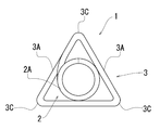
- FIG. 1 is a schematic view showing a first embodiment of a drop-off prevention device to which the present invention is applied.
- FIG. 2 is a schematic plan view of the dropout prevention tool of the present invention shown in FIG.
- a dropout prevention device 1 according to the first embodiment of the present invention shown in FIG. 1 includes a coil spring portion 2 in which a coil wire 2A is wound in a substantially circular shape with substantially the same diameter.
- the diameter of the coil spring portion 2 is slightly smaller than the outer diameter of the leg portion of the bolt.
- the dropout prevention device 1 of the present invention includes an overhang portion 3.
- the overhang portion 3 has an extension coil strand 3A extending from one end of the coil strand 2A constituting the coil spring portion 2 in a winding range larger than the winding range of the coil spring portion 2, and the coil spring portion 2
- the three top portions 3C are concentrically wound in a substantially triangular shape, which is a shape that is disposed at substantially the same distance from the winding center of the coil spring portion 2.
- the overhang portion 3 is formed by winding an extended coil element wire 3 ⁇ / b> A extending in a substantially straight line in the tangential direction outside the coil spring portion 2. That is, the substantially linear portion of the overhang portion 3 is located outside the outer diameter of the coil spring portion 2 and can invite the fitting of the drop prevention tool 1 of the present invention to the leg portion of the bolt. .
- the overhang portion 3 is a region within a predetermined range from the tip of the extended coil strand 3A that is separated from one end of the coil strand 2A, and the coil spring portion 2 in the same direction as the direction in which the winding center of the coil spring portion 2 extends. End region 3B arranged on the side away from the center.
- “disposed on the side away from the coil spring portion in the same direction as the direction in which the winding center of the coil spring portion extends” means that, for example, as shown in FIG. When viewed from the part 2 side in the same direction as the direction in which the winding center of the coil spring part 2 extends, it means that the coil spring part 2 is disposed on the other side of the other region of the extension coil strand 3A.
- the end region 3B is colored in a color different from the colors of other regions, that is, the other regions of the extension coil strand 3A and the region of the coil strand 2A, for example, red, green, or yellow.
- FIG. 3 is a schematic plan view showing a state in which the dropout prevention device of the present invention shown in FIG. 1 is attached to a bolt and a nut.
- illustration of a to-be-fixed object is abbreviate
- the coil spring portion 2 is guided, and the coil wire 2A of the coil spring portion 2 is also fitted into the thread groove of the bolt 4, so that quick insertion and mounting are possible. it can.
- the colored end region 3B is formed on the overhang portion 3 as shown in FIG. It is pushed out to the outside of the winding range, that is, the side away from the winding center of the overhang portion 3, and is easily confirmed from the outside.
- the user can know that the drop-off prevention tool 1 of the present invention is firmly pressed against the nut 5, and can visually confirm the effect of the drop-off prevention.
- projection part 3 hits the end surface of the nut 5, ie, the surface shown in FIG. 3, and the force which suppresses the left rotation of the nut 5 generate
- the end region 3B is pushed out to the side away from the winding center of the overhanging portion 3, the end region 3B tends to return to the original position, and thus a tightening force to the bolt 4 is generated.
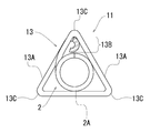
- FIG. 4 is a schematic plan view showing a second embodiment of a drop-off prevention device to which the present invention is applied.
- FIGS. 4 and 5 showing the second embodiment the same members as those in the first embodiment are denoted by the same reference numerals as those in the first embodiment.
- the overhang portion 13 has a winding range in which the extension coil strand 13A extending from one end of the coil strand 2A constituting the coil spring portion 2 is larger than the winding range of the coil spring portion 2, and the coil spring portion 2
- the three top portions 13C are concentrically wound and formed in a substantially triangular shape, which is a shape that is disposed at substantially the same distance from the winding center of the coil spring portion 2.
- the overhanging portion 13 is configured by winding the extended coil element wire 13 ⁇ / b> A so as to extend substantially linearly in the tangential direction outside the coil spring portion 2.
- the overhanging portion 13 is a region in a predetermined range from the tip of the extended coil strand 13A that is separated from one end of the coil strand 2A, and the coil spring portion 2 is in the same direction as the direction in which the winding center of the coil spring portion 2 extends. And an end region 13B disposed on the side away from the center.
- the end region 13 ⁇ / b> B is outside the winding range of the coil spring portion 2 and is curved to protrude into the winding range of the overhang portion 13.
- end region 13B is colored in a color different from the colors of the other regions, that is, the other region of the extended coil wire 13A and the region of the coil wire 2A.
- FIG. 5 is a schematic plan view showing a state in which the dropout prevention device of the present invention shown in FIG. 4 is attached to a bolt and a nut.
- illustration of the to-be-fixed object is abbreviate
- the drop-off prevention tool 11 according to the second embodiment of the present invention attaches the overhanging portion 13 to the bolt 4 when the bolt 4 is attached to the leg portion.
- the drop prevention tool 11 of the present invention is rotated rightward while pressing against the leg of the bolt 4 toward the leg.
- the colored end region 13B is wound on the overhanging portion 13 as shown in FIG. It is pushed out to the outside of the turning range, that is, the side away from the winding center of the overhanging portion 13, and is easily confirmed from the outside.
- the user can know that the drop-off prevention tool 11 of the present invention is firmly pressed against the nut 5, and can visually confirm the effect of the drop-off prevention.
- the end region 13B is curved outside the winding range of the coil spring portion 2 and protruding into the winding range of the overhang portion 13. Therefore, the projected and curved end region 13B hits a region other than the end region of the overhang 13 and is pushed outward. Then, as the end region 13B hits the region other than the end region of the overhang portion 13 and is further pushed out, a force to return to the end region 13B is generated, and the fall prevention tool 11 of the present invention is contracted. Can give power.
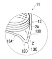
- FIG. 6 is a schematic partially enlarged view showing a modified example of the dropout prevention tool of the second embodiment to which the present invention is applied.
- the fixed regions on both sides centered on the top portion 13 ⁇ / b> C are provided with the inclined portions 13 ⁇ / b> D, so that the coil spring portion 2 has a larger area than the other regions, i. It is located on the side away from the coil spring portion 2 in the same direction as the direction in which the winding center extends. That is, certain regions on both sides centering on the top portion 13C are inclined downward in FIG.
- this constant region sufficiently hits the nut, and the force for suppressing the left rotation of the nut can be improved.
- the boundary region where the end surface of the nut and the side surface substantially orthogonal to the end surface of the nut are in contact with each other is a fixed region on both sides centered on the top portion 13C as shown in FIG.
- the constant areas on both sides centering on the top part 13C are It is possible to improve the force that sufficiently hits the inclined boundary region of the nut and suppresses the left rotation of the nut.
- the inclination of the boundary region of the nut is not shown.
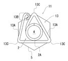
- FIG. 7 is a schematic plan view showing a state in which the dropout prevention tool of the third embodiment to which the present invention is applied is mounted on a bolt and a nut.
- the same members as those in the first embodiment are denoted by the same reference numerals as those in the first embodiment. Further, in FIG. 7, the illustration of the fixed object is omitted.
- the overhang portion 23 has an extension coil strand 23A extending from one end of the coil strand 2A constituting the coil spring portion 2 in a winding range larger than the winding range of the coil spring portion 2, and the coil spring portion 2
- the three top portions 23C are concentrically wound in a substantially triangular shape that is disposed at substantially the same distance from the winding center of the coil spring portion 2, and further, another top portion 23C is formed. It is configured to be wound.
- the overhang portion 23 is configured by extending the extended coil wire 23 ⁇ / b> A so as to extend substantially linearly in the tangential direction outside the coil spring portion 2 at two locations.
- the overhang portion 23 is a region in a predetermined range from the tip of the extended coil strand 23A that is separated from one end of the coil strand 2A, and is in the same direction as the direction in which the winding center of the coil spring portion 2 extends. End portion 23B disposed on the side away from the center.
- end region 23B is colored in a color different from the colors of the other regions, that is, the other region of the extension coil wire 23A and the region of the coil wire 2A.
- the dropout prevention device 21 of the third embodiment of the present invention is attached to the leg portion of the bolt 4, and the overhang portion 23 is attached to the bolt 4.
- the drop prevention tool 21 of the present invention is rotated to the right while being pressed against the leg of the bolt 4 toward the leg.
- the colored end region 23B is wound on the overhang portion 23 as shown in FIG. It is pushed out of the winding range from the one end of the coil wire 2A to the third top 23C in the winding range, that is, the side away from the winding center of the overhang 23, and is easily confirmed from the outside.
- the user can know that the drop-off prevention tool 21 of the present invention is firmly pressed against the nut 5, and can visually confirm the effect of the drop-off prevention.
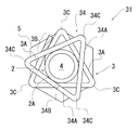
- FIG. 8 is a schematic view showing a fourth embodiment of a drop-off prevention device to which the present invention is applied.
- a dropout prevention tool 31 according to the fourth embodiment of the present invention shown in FIG. 8 includes a coil spring portion 2 in which a coil wire 2A is wound in a substantially circular shape with substantially the same diameter.
- the diameter of the coil spring portion 2 is slightly smaller than the outer diameter of the leg portion of the bolt.
- the dropout prevention tool 31 of the present invention includes the overhang portion 3 and the additional overhang portion 34.
- the overhang portion 3 has an extension coil strand 3A extending from one end of the coil strand 2A constituting the coil spring portion 2 in a winding range larger than the winding range of the coil spring portion 2, and the coil spring portion 2
- the three top portions 3C are concentrically wound in a substantially triangular shape, which is a shape that is disposed at substantially the same distance from the winding center of the coil spring portion 2.
- the overhang portion 3 is configured by winding the extended coil element wire 3 ⁇ / b> A so as to extend substantially linearly in the tangential direction outside the coil spring portion 2.
- the overhang portion 3 is a predetermined region from the tip of the extended coil strand 3A that is separated from one end of the coil strand 2A, and is separated from the coil spring portion 2 in the same direction as the direction in which the winding center of the coil spring portion 2 extends. It has an end region 3B arranged on the side.
- end region 3B is colored in a color different from the colors of the other regions, that is, the other region of the extension coil strand 3A and the region of the coil strand 2A.
- the additional overhang portion 34 has an extension coil strand 34A extending from the other end of the coil strand 2A constituting the coil spring portion 2 in a winding range larger than the winding range of the coil spring portion 2, and the coil spring portion 2
- the three top portions 34 ⁇ / b> C are wound in a substantially triangular shape, which is a shape arranged at substantially the same distance from the winding center of the coil spring portion 2.
- the additional overhang portion 34 is configured by winding an extended coil element wire 34 ⁇ / b> A extending substantially linearly in the tangential direction outside the coil spring portion 2.
- the additional overhang portion 34 is a coil spring in the same direction as the direction in which the winding center of the coil spring portion 2 extends and is a region within a predetermined range from the tip of the extended coil wire 34A that is separated from the other end of the coil strand 2A. It has an additional end region 34 ⁇ / b> B arranged on the side away from the part 2.
- the additional end region 34B is not colored.
- the overhang portion 3 colored in the end region 3B is directed toward the leg portion of the bolt. Rotate clockwise while pressing the drop-off prevention tool 31 against the leg of the bolt.
- an uncolored additional end region and a colored end region are provided, the overhanging portion where the end region is colored is directed to the leg of the bolt, and the dropout prevention device of the present invention is attached to the bolt.
- the reason for attaching to the leg is as follows.
- the fall prevention device of the present invention if the fall prevention device of the present invention is attached to the leg portion of the bolt, the fall prevention device of the present invention continues to rotate clockwise, and the colored end region is pressed against the nut and colored. The end region is pushed to the side away from the winding center of the overhanging portion, and it is easy to confirm from the outside. As a result, the user confirms that the fall-off prevention device of the present invention is firmly pressed against the nut. This is because it is easy to recognize.
- the colored region that is not pressed against the nut is also confirmed from the outside, and the user can prevent the falling of the present invention. This is because it becomes difficult to recognize that the tool is firmly pressed against the nut.
- the fall prevention tool 31 of the 4th Embodiment of this invention is a user. Since it is easy to fit the straight portion into the screw groove in the same way regardless of which of the overhanging portion 3 and the additional overhanging portion 34 is attached to the bolt, without worrying about the direction of the drop-off prevention device 31 of the present invention. Can be attached to bolts.
- the dropout prevention tool 31 of the fourth embodiment of the present invention includes the overhang portion 3 and the additional overhang portion 34 that are configured by winding the extension coil strands in a substantially triangular shape. A person can grab either one and apply rotation to the dropout prevention tool 31 of the present invention, and easily rotate the dropout prevention tool 31 of the present invention.
- FIG. 9 is a schematic plan view showing a state in which the dropout prevention device of the fourth embodiment to which the present invention is applied is mounted on a bolt and a nut.
- illustration of the to-be-fixed object is abbreviate
- the overhang portion 3 is directed to the leg portion of the bolt 4, and the drop prevention tool 31 of the present invention is attached to the bolt 4. Rotate clockwise while pressing against the leg.
- the end region 3B is pressed against the nut 5 while continuing the right rotation of the drop-off prevention tool 31 of the present invention
- the colored end region 3B is formed on the overhang portion 3 as shown in FIG. It is pushed away from the winding center and easily confirmed from the outside.
- the user can know that the drop-off prevention tool 31 of the present invention is firmly pressed against the nut 5 and can visually confirm the effect of preventing the drop-off.
- projection part 3 contacts the end surface of a nut, ie, the surface shown in FIG. 9, and the force which suppresses the left rotation of the nut 5 generate
- the end region 3B is pushed out to the side away from the winding center of the overhanging portion 3, the end region 3B tends to return to the original position, and thus a tightening force to the bolt 4 is generated.
- the drop prevention tool 31 is attached to the leg portion where the screw groove of the bolt 4 is formed, but the top portion 3C of the overhang portion 3 and the top portion 34C of the additional overhang portion 34 are not shown. Are arranged on substantially the same line in the same direction as the direction in which the winding center of the coil spring portion 2 extends.
- the top portion 3C of the overhang portion 3 and the top portion of the additional overhang portion 34 are provided.
- 34C is not disposed on the same line in the same direction as the direction in which the winding center of the coil spring portion 2 extends.
- the user can confirm not only the colored end region 3B but also the substantially hexagonal shape from the outside, it is easier to visually confirm the effect of preventing the dropout.
- extension coil wire is wound in a polygonal shape, it does not necessarily have to be wound in a substantially triangular shape.
- the extension coil wire may be wound in a substantially pentagonal shape or a substantially hexagonal shape.
- the straight portion can be fitted into the screw groove of the bolt more stably than in the case of being wound in a substantially square shape or a substantially pentagonal shape. preferable.
- the end region does not necessarily have to be colored in a color different from the color of other regions. However, it is preferable that the end region is colored in a color different from the color of other regions because the user can more easily visually confirm the effect of preventing the dropout.
- the overhanging portion and the additional overhanging portion do not necessarily have the same shape.
- the overhanging portion may have a substantially triangular shape, and the additional overhanging portion may have a substantially hexagonal shape.
- the overhanging part and the additional overhanging part have the same shape, the user can fit the straight part into the screw groove in the same way regardless of whether the overhanging part or the additional overhanging part is attached to the bolt. Since it is easy, there exists an advantage that it can mount
- the drop-off prevention device of the present invention is such that the extension coil wire extending from one end of the coil wire constituting the coil spring portion has a winding range larger than the winding range of the coil spring portion and is concentric with the coil spring portion. And a plurality of top portions are wound in a polygonal shape, which is a shape arranged at substantially the same distance from the winding center of the coil spring portion, and extending in a substantially straight line in the tangential direction of the coil spring portion. Since the projecting portion is provided, at least three straight portions of the extension coil element wire can be fitted into the screw groove of the bolt.
- the drop-off preventing device of the present invention is a region within a predetermined range from the tip of the extended coil wire separated from one end of the coil wire, and is separated from the coil spring portion in the same direction as the direction in which the winding center of the coil spring portion extends.
- the drop-off preventing device of the present invention is a region within a predetermined range from the tip of the extended coil wire separated from one end of the coil wire, and is separated from the coil spring portion in the same direction as the direction in which the winding center of the coil spring portion extends. Since the overhanging portion having the end region arranged on the side is provided, when the overhanging portion is arranged on the nut side, the end region pressed against the nut is outside the winding range of the overhanging portion, that is, Extruded to the side away from the winding center, the user can visually confirm the effect of preventing the dropout.
- the drop-off prevention device of the present invention can be easily rotated with a hand or a general-purpose tool, and can be easily attached to the bolt.
- the end region is colored in a color different from the color of other regions, the user can more easily visually confirm the effect of preventing the drop-off compared to the case where the end region is not colored.
Landscapes
- Engineering & Computer Science (AREA)
- General Engineering & Computer Science (AREA)
- Mechanical Engineering (AREA)
- Hand Tools For Fitting Together And Separating, Or Other Hand Tools (AREA)
Applications Claiming Priority (2)
| Application Number | Priority Date | Filing Date | Title |
|---|---|---|---|
| JP2015-250352 | 2015-12-22 | ||
| JP2015250352A JP6179926B2 (ja) | 2015-12-22 | 2015-12-22 | 脱落防止具 |
Publications (1)
| Publication Number | Publication Date |
|---|---|
| WO2017110852A1 true WO2017110852A1 (ja) | 2017-06-29 |
Family
ID=59089419
Family Applications (1)
| Application Number | Title | Priority Date | Filing Date |
|---|---|---|---|
| PCT/JP2016/088054 Ceased WO2017110852A1 (ja) | 2015-12-22 | 2016-12-21 | 脱落防止具 |
Country Status (2)
| Country | Link |
|---|---|
| JP (1) | JP6179926B2 (enExample) |
| WO (1) | WO2017110852A1 (enExample) |
Families Citing this family (6)
| Publication number | Priority date | Publication date | Assignee | Title |
|---|---|---|---|---|
| JP6767010B2 (ja) * | 2016-09-14 | 2020-10-14 | 有限会社Sit | 脱落防止具 |
| KR101817948B1 (ko) * | 2017-08-10 | 2018-01-12 | 조정현 | 풀림방지너트 |
| KR101929887B1 (ko) | 2018-04-25 | 2018-12-17 | 이방희 | 재사용 가능한 풀림방지용 스프링 와셔 |
| JP7045065B2 (ja) * | 2018-07-20 | 2022-03-31 | 有限会社Sit | 脱落防止具 |
| KR101986509B1 (ko) * | 2018-09-13 | 2019-06-10 | 주식회사 한국자동화기술 | 풀림 방지 와셔가 구비된 너트 |
| WO2021210057A1 (ja) * | 2020-04-14 | 2021-10-21 | イイファス株式会社 | 戻り止めナット |
Citations (4)
| Publication number | Priority date | Publication date | Assignee | Title |
|---|---|---|---|---|
| JP2004100952A (ja) * | 2002-08-20 | 2004-04-02 | Chuo Hatsujo Kogyo Kk | ボルト・ナットの緩み止め具及びボルトの締結具 |
| JP2011027178A (ja) * | 2009-07-24 | 2011-02-10 | Yarisute:Kk | ナットの脱落防止具およびその取付治具 |
| WO2011145212A1 (ja) * | 2010-05-21 | 2011-11-24 | Soeda Taijiro | 脱落防止具 |
| JP2016156482A (ja) * | 2015-02-26 | 2016-09-01 | 大成建設株式会社 | 脱落防止具 |
Family Cites Families (2)
| Publication number | Priority date | Publication date | Assignee | Title |
|---|---|---|---|---|
| JPS6298015A (ja) * | 1985-10-22 | 1987-05-07 | 森電機株式会社 | ボルトの脱落又は紛失防止装置 |
| JP3848309B2 (ja) * | 2003-09-11 | 2006-11-22 | 中央発条工業株式会社 | 脱落防止具 |
-
2015
- 2015-12-22 JP JP2015250352A patent/JP6179926B2/ja active Active
-
2016
- 2016-12-21 WO PCT/JP2016/088054 patent/WO2017110852A1/ja not_active Ceased
Patent Citations (4)
| Publication number | Priority date | Publication date | Assignee | Title |
|---|---|---|---|---|
| JP2004100952A (ja) * | 2002-08-20 | 2004-04-02 | Chuo Hatsujo Kogyo Kk | ボルト・ナットの緩み止め具及びボルトの締結具 |
| JP2011027178A (ja) * | 2009-07-24 | 2011-02-10 | Yarisute:Kk | ナットの脱落防止具およびその取付治具 |
| WO2011145212A1 (ja) * | 2010-05-21 | 2011-11-24 | Soeda Taijiro | 脱落防止具 |
| JP2016156482A (ja) * | 2015-02-26 | 2016-09-01 | 大成建設株式会社 | 脱落防止具 |
Also Published As
| Publication number | Publication date |
|---|---|
| JP2017115939A (ja) | 2017-06-29 |
| JP6179926B2 (ja) | 2017-08-16 |
Similar Documents
| Publication | Publication Date | Title |
|---|---|---|
| JP6179926B2 (ja) | 脱落防止具 | |
| KR101625007B1 (ko) | 풀림방지 볼트조립체 | |
| KR101560737B1 (ko) | 풀림방지볼트 | |
| JP5200190B2 (ja) | 脱落防止具 | |
| JP2014523829A5 (enExample) | ||
| US20100098511A1 (en) | Locking system and fastening elements | |
| JP7045065B2 (ja) | 脱落防止具 | |
| WO2013161047A1 (ja) | 脱落防止具 | |
| WO2014087131A1 (en) | Locknut assembly | |
| JP2017190793A (ja) | 脱落防止具 | |
| JP2017198344A (ja) | 脱落防止具 | |
| JP3188237U (ja) | ワッシャー付ナット | |
| KR101817948B1 (ko) | 풀림방지너트 | |
| JP6784374B2 (ja) | 脱落防止具 | |
| WO2020162522A1 (ja) | 脱落防止具 | |
| JPWO2018155466A1 (ja) | 脱落防止具 | |
| JP7442185B2 (ja) | 脱落防止具 | |
| JP3182560U (ja) | 多重緩み止めナット | |
| KR102413084B1 (ko) | 풀림방지너트 | |
| JP5918428B1 (ja) | 落下防止具 | |
| JP7012035B2 (ja) | 締結器具 | |
| KR20160002742U (ko) | 셋트 앙카 볼트 | |
| JPH0632497Y2 (ja) | ねじ部品の緩み止め装置 | |
| JP4409477B2 (ja) | 締結体の弛み止め機構 | |
| JP2019138466A (ja) | 締結ナットの脱落防止装置 |
Legal Events
| Date | Code | Title | Description |
|---|---|---|---|
| 121 | Ep: the epo has been informed by wipo that ep was designated in this application |
Ref document number: 16878739 Country of ref document: EP Kind code of ref document: A1 |
|
| NENP | Non-entry into the national phase |
Ref country code: DE |
|
| 122 | Ep: pct application non-entry in european phase |
Ref document number: 16878739 Country of ref document: EP Kind code of ref document: A1 |