WO2017110852A1 - Falling-off prevention tool - Google Patents
Falling-off prevention tool Download PDFInfo
- Publication number
- WO2017110852A1 WO2017110852A1 PCT/JP2016/088054 JP2016088054W WO2017110852A1 WO 2017110852 A1 WO2017110852 A1 WO 2017110852A1 JP 2016088054 W JP2016088054 W JP 2016088054W WO 2017110852 A1 WO2017110852 A1 WO 2017110852A1
- Authority
- WO
- WIPO (PCT)
- Prior art keywords
- coil spring
- spring portion
- coil
- winding
- region
- Prior art date
Links
- 230000002265 prevention Effects 0.000 title claims abstract description 91
- 238000004804 winding Methods 0.000 claims abstract description 49
- 230000000694 effects Effects 0.000 description 14
- 238000000034 method Methods 0.000 description 5
- 239000003086 colorant Substances 0.000 description 4
- 238000003466 welding Methods 0.000 description 3
- 239000002184 metal Substances 0.000 description 2
- 238000010276 construction Methods 0.000 description 1
- 230000008602 contraction Effects 0.000 description 1
- 238000003780 insertion Methods 0.000 description 1
- 230000037431 insertion Effects 0.000 description 1
- 230000004048 modification Effects 0.000 description 1
- 238000012986 modification Methods 0.000 description 1
Images


Classifications
-
- F—MECHANICAL ENGINEERING; LIGHTING; HEATING; WEAPONS; BLASTING
- F16—ENGINEERING ELEMENTS AND UNITS; GENERAL MEASURES FOR PRODUCING AND MAINTAINING EFFECTIVE FUNCTIONING OF MACHINES OR INSTALLATIONS; THERMAL INSULATION IN GENERAL
- F16B—DEVICES FOR FASTENING OR SECURING CONSTRUCTIONAL ELEMENTS OR MACHINE PARTS TOGETHER, e.g. NAILS, BOLTS, CIRCLIPS, CLAMPS, CLIPS OR WEDGES; JOINTS OR JOINTING
- F16B39/00—Locking of screws, bolts or nuts
- F16B39/02—Locking of screws, bolts or nuts in which the locking takes place after screwing down
- F16B39/20—Locking of screws, bolts or nuts in which the locking takes place after screwing down by means of steel wire or the like
-
- F—MECHANICAL ENGINEERING; LIGHTING; HEATING; WEAPONS; BLASTING
- F16—ENGINEERING ELEMENTS AND UNITS; GENERAL MEASURES FOR PRODUCING AND MAINTAINING EFFECTIVE FUNCTIONING OF MACHINES OR INSTALLATIONS; THERMAL INSULATION IN GENERAL
- F16B—DEVICES FOR FASTENING OR SECURING CONSTRUCTIONAL ELEMENTS OR MACHINE PARTS TOGETHER, e.g. NAILS, BOLTS, CIRCLIPS, CLAMPS, CLIPS OR WEDGES; JOINTS OR JOINTING
- F16B39/00—Locking of screws, bolts or nuts
- F16B39/22—Locking of screws, bolts or nuts in which the locking takes place during screwing down or tightening
- F16B39/28—Locking of screws, bolts or nuts in which the locking takes place during screwing down or tightening by special members on, or shape of, the nut or bolt
- F16B39/34—Locking by deformable inserts or like parts
-
- F—MECHANICAL ENGINEERING; LIGHTING; HEATING; WEAPONS; BLASTING
- F16—ENGINEERING ELEMENTS AND UNITS; GENERAL MEASURES FOR PRODUCING AND MAINTAINING EFFECTIVE FUNCTIONING OF MACHINES OR INSTALLATIONS; THERMAL INSULATION IN GENERAL
- F16B—DEVICES FOR FASTENING OR SECURING CONSTRUCTIONAL ELEMENTS OR MACHINE PARTS TOGETHER, e.g. NAILS, BOLTS, CIRCLIPS, CLAMPS, CLIPS OR WEDGES; JOINTS OR JOINTING
- F16B41/00—Measures against loss of bolts, nuts, or pins; Measures against unauthorised operation of bolts, nuts or pins
Definitions
- the present invention relates to a drop-off prevention device. Specifically, the present invention relates to a drop-off prevention tool that prevents the fixed object and nut from falling off the bolt.
- a method for fixing two members constituting a building structure a method of fixing by welding or a method of fastening by bolts and nuts is used.
- fixing by welding requires welding equipment, and it takes time and labor for construction. Also, equipment is required for releasing the fixing, and it takes time and effort to release the fixing. Many methods are adopted.
- Patent Literature 1 describes a nut 401 with a locking function as shown in FIG. That is, the nut 401 with a locking function described in Patent Document 1 includes a locking tool 403 and a hex nut 102.
- the loosening stop 403 includes a loosening coil portion 103A around which a metal wire is wound with substantially the same diameter, and the outer edge of the hexagon nut 102 that extends outward in a tangential direction from the lower end of the loosening coil portion 103A. And an automatic tightening adjustment unit 410 composed of a drawn metal wire.
- the loose fastener 403 is bent downward from the upper end of the loose coil portion 103A, is an annular narrow groove, and is a nut that can be engaged with the loose fastener engaging portion 430 formed on the upper surface of the hexagon nut 102.
- An engaging portion 420 is provided.
- the nut engaging part 420 is comprised by the part 103B wound larger than the diameter of the loosening coil part 103A, and the part 103C engaged with the hexagon nut 102.
- Patent Document 1 has an automatic tightening adjustment portion as a straight portion, the automatic tightening adjustment portion is not configured to be fitted into the screw groove of the bolt. There was a problem that it was difficult to attach the tool to the bolt.
- the present invention has been made in view of the above points, and an object thereof is to provide a drop-off preventing tool that can be easily attached to a bolt.
- the drop-off prevention device of the present invention includes a coil spring portion in which a coil wire is wound in a substantially circular shape with substantially the same diameter, and one end of the coil wire constituting the coil spring portion.
- the extending extension coil wire has a winding range larger than the winding range of the coil spring portion, is concentric with the coil spring portion, and a plurality of top portions are substantially the same distance from the winding center of the coil spring portion.
- the tip of the extended coil wire that is wound in a polygonal shape that is a shape arranged in a straight line extending in a tangential direction of the coil spring portion and that is separated from one end of the coil wire And a projecting portion having an end region disposed on the side away from the coil spring portion in the same direction as the direction in which the winding center of the coil spring portion extends.
- the coil element wire can be fitted to the leg portion of the bolt by the coil spring portion wound in a substantially circular shape with the substantially same diameter.
- the extension coil wire extending from one end of the coil wire constituting the coil spring portion is in a winding range larger than the winding range of the coil spring portion, concentric with the coil spring portion, and a plurality of top portions are coil spring portions. At least one of the extended coil strands by an overhanging portion that is wound in a polygonal shape, which is a shape that is disposed at substantially the same distance from the winding center of the wire, and that extends substantially linearly in the tangential direction of the coil spring portion. Three straight portions can be fitted into the screw grooves of the bolt.
- the end region disposed on the side away from the coil spring portion in the same direction as the direction in which the winding center of the coil spring portion extends is a region within a predetermined range from the tip of the extension coil strand separated from one end of the coil wire. Since the overhanging portion is not formed so as to surround the coil spring portion, it is easy to fit at least three straight portions of the extension coil wire into the screw groove of the bolt.
- the end region disposed on the side away from the coil spring portion in the same direction as the direction in which the winding center of the coil spring portion extends is a region within a predetermined range from the tip of the extension coil strand separated from one end of the coil wire.
- the end region can be curved outside the winding range of the coil spring portion and protruding into the winding range of the overhang portion.
- the end region pressed against the nut is pushed outside the winding range of the overhanging portion, and further, the protruding end region hits the region other than the end region of the overhanging portion and goes outward. Extruded. Then, a force to return to the end region is generated as much as the end region hits and is pushed out, and a contraction force can be applied to the drop-off prevention device.
- the overhanging portion can be formed by winding the extension coil wire in a substantially triangular shape.
- the three straight portions of the extension coil can be fitted into the bolt groove.
- the drop-off prevention device of the present invention is such that the extension coil strand extending from the other end of the coil strand constituting the coil spring portion is in a winding range larger than the winding range of the coil spring portion and concentrically with the coil spring portion.
- a plurality of top portions are wound in a polygonal shape, which is a shape that is arranged at substantially the same distance from the winding center of the coil spring portion, and extending substantially linearly in the tangential direction of the coil spring portion, And the additional end which is the area
- the extension coil strand extending from the other end of the coil strand constituting the coil spring portion is in a winding range larger than the winding range of the coil spring portion, concentrically with the coil spring portion, and a plurality of top portions are coil springs.
- the additional overhanging portion wound in a polygonal shape which is a shape arranged at substantially the same distance from the winding center of the portion, and extending substantially linearly in the tangential direction of the coil spring portion, the user can It is easy to rotate the drop-off prevention tool by grasping the additional overhanging part by hand or general-purpose tool.
- the additional end is a region within a predetermined range from the tip of the extension coil wire separated from the other end of the coil wire, and is disposed on the side away from the coil spring portion in the same direction as the direction in which the winding center of the coil spring portion extends.
- the additional overhanging portion having a region is arranged on the nut side, the additional end region pressed against the nut is outside the winding range of the additional overhanging portion, that is, the side away from the winding center.
- the user can visually confirm the effect of preventing the dropout. In other words, even if the fall prevention tool is attached to the bolt from the overhanging part side, or the fall prevention tool is attached to the bolt from the additional overhanging part side, the user can visually confirm the effect of the fall prevention. it can.
- the extension coil wire is wound in a substantially triangular shape, and the additional extension portion is formed by winding the extension coil wire in a substantially triangular shape. It can be.
- the user can easily fit the straight part into the screw groove regardless of whether the extension part or the additional extension part is attached to the bolt. Can be attached to.
- the end region can be colored in a color different from the color of other regions.
- the top portion of the overhanging portion is disposed on the side away from the coil spring portion in the same direction as the direction in which the winding center of the coil spring portion extends from the substantially linear region of the overhanging portion. Can be.
- the top portion sufficiently hits the inclined boundary region of the nut, and the force for suppressing the left rotation of the nut can be improved.
- the drop-off prevention tool according to the present invention can be easily attached to the bolt.
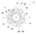
- FIG. 1 is a schematic view showing a first embodiment of a drop-off prevention device to which the present invention is applied.
- FIG. 2 is a schematic plan view of the dropout prevention tool of the present invention shown in FIG.
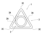
- a dropout prevention device 1 according to the first embodiment of the present invention shown in FIG. 1 includes a coil spring portion 2 in which a coil wire 2A is wound in a substantially circular shape with substantially the same diameter.
- the diameter of the coil spring portion 2 is slightly smaller than the outer diameter of the leg portion of the bolt.
- the dropout prevention device 1 of the present invention includes an overhang portion 3.
- the overhang portion 3 has an extension coil strand 3A extending from one end of the coil strand 2A constituting the coil spring portion 2 in a winding range larger than the winding range of the coil spring portion 2, and the coil spring portion 2
- the three top portions 3C are concentrically wound in a substantially triangular shape, which is a shape that is disposed at substantially the same distance from the winding center of the coil spring portion 2.
- the overhang portion 3 is formed by winding an extended coil element wire 3 ⁇ / b> A extending in a substantially straight line in the tangential direction outside the coil spring portion 2. That is, the substantially linear portion of the overhang portion 3 is located outside the outer diameter of the coil spring portion 2 and can invite the fitting of the drop prevention tool 1 of the present invention to the leg portion of the bolt. .
- the overhang portion 3 is a region within a predetermined range from the tip of the extended coil strand 3A that is separated from one end of the coil strand 2A, and the coil spring portion 2 in the same direction as the direction in which the winding center of the coil spring portion 2 extends. End region 3B arranged on the side away from the center.
- “disposed on the side away from the coil spring portion in the same direction as the direction in which the winding center of the coil spring portion extends” means that, for example, as shown in FIG. When viewed from the part 2 side in the same direction as the direction in which the winding center of the coil spring part 2 extends, it means that the coil spring part 2 is disposed on the other side of the other region of the extension coil strand 3A.
- the end region 3B is colored in a color different from the colors of other regions, that is, the other regions of the extension coil strand 3A and the region of the coil strand 2A, for example, red, green, or yellow.
- FIG. 3 is a schematic plan view showing a state in which the dropout prevention device of the present invention shown in FIG. 1 is attached to a bolt and a nut.
- illustration of a to-be-fixed object is abbreviate
- the coil spring portion 2 is guided, and the coil wire 2A of the coil spring portion 2 is also fitted into the thread groove of the bolt 4, so that quick insertion and mounting are possible. it can.
- the colored end region 3B is formed on the overhang portion 3 as shown in FIG. It is pushed out to the outside of the winding range, that is, the side away from the winding center of the overhang portion 3, and is easily confirmed from the outside.
- the user can know that the drop-off prevention tool 1 of the present invention is firmly pressed against the nut 5, and can visually confirm the effect of the drop-off prevention.
- projection part 3 hits the end surface of the nut 5, ie, the surface shown in FIG. 3, and the force which suppresses the left rotation of the nut 5 generate
- the end region 3B is pushed out to the side away from the winding center of the overhanging portion 3, the end region 3B tends to return to the original position, and thus a tightening force to the bolt 4 is generated.
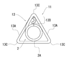
- FIG. 4 is a schematic plan view showing a second embodiment of a drop-off prevention device to which the present invention is applied.
- FIGS. 4 and 5 showing the second embodiment the same members as those in the first embodiment are denoted by the same reference numerals as those in the first embodiment.
- the overhang portion 13 has a winding range in which the extension coil strand 13A extending from one end of the coil strand 2A constituting the coil spring portion 2 is larger than the winding range of the coil spring portion 2, and the coil spring portion 2
- the three top portions 13C are concentrically wound and formed in a substantially triangular shape, which is a shape that is disposed at substantially the same distance from the winding center of the coil spring portion 2.
- the overhanging portion 13 is configured by winding the extended coil element wire 13 ⁇ / b> A so as to extend substantially linearly in the tangential direction outside the coil spring portion 2.
- the overhanging portion 13 is a region in a predetermined range from the tip of the extended coil strand 13A that is separated from one end of the coil strand 2A, and the coil spring portion 2 is in the same direction as the direction in which the winding center of the coil spring portion 2 extends. And an end region 13B disposed on the side away from the center.
- the end region 13 ⁇ / b> B is outside the winding range of the coil spring portion 2 and is curved to protrude into the winding range of the overhang portion 13.
- end region 13B is colored in a color different from the colors of the other regions, that is, the other region of the extended coil wire 13A and the region of the coil wire 2A.
- FIG. 5 is a schematic plan view showing a state in which the dropout prevention device of the present invention shown in FIG. 4 is attached to a bolt and a nut.
- illustration of the to-be-fixed object is abbreviate
- the drop-off prevention tool 11 according to the second embodiment of the present invention attaches the overhanging portion 13 to the bolt 4 when the bolt 4 is attached to the leg portion.
- the drop prevention tool 11 of the present invention is rotated rightward while pressing against the leg of the bolt 4 toward the leg.
- the colored end region 13B is wound on the overhanging portion 13 as shown in FIG. It is pushed out to the outside of the turning range, that is, the side away from the winding center of the overhanging portion 13, and is easily confirmed from the outside.
- the user can know that the drop-off prevention tool 11 of the present invention is firmly pressed against the nut 5, and can visually confirm the effect of the drop-off prevention.
- the end region 13B is curved outside the winding range of the coil spring portion 2 and protruding into the winding range of the overhang portion 13. Therefore, the projected and curved end region 13B hits a region other than the end region of the overhang 13 and is pushed outward. Then, as the end region 13B hits the region other than the end region of the overhang portion 13 and is further pushed out, a force to return to the end region 13B is generated, and the fall prevention tool 11 of the present invention is contracted. Can give power.
- FIG. 6 is a schematic partially enlarged view showing a modified example of the dropout prevention tool of the second embodiment to which the present invention is applied.
- the fixed regions on both sides centered on the top portion 13 ⁇ / b> C are provided with the inclined portions 13 ⁇ / b> D, so that the coil spring portion 2 has a larger area than the other regions, i. It is located on the side away from the coil spring portion 2 in the same direction as the direction in which the winding center extends. That is, certain regions on both sides centering on the top portion 13C are inclined downward in FIG.
- this constant region sufficiently hits the nut, and the force for suppressing the left rotation of the nut can be improved.
- the boundary region where the end surface of the nut and the side surface substantially orthogonal to the end surface of the nut are in contact with each other is a fixed region on both sides centered on the top portion 13C as shown in FIG.
- the constant areas on both sides centering on the top part 13C are It is possible to improve the force that sufficiently hits the inclined boundary region of the nut and suppresses the left rotation of the nut.
- the inclination of the boundary region of the nut is not shown.
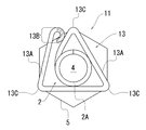
- FIG. 7 is a schematic plan view showing a state in which the dropout prevention tool of the third embodiment to which the present invention is applied is mounted on a bolt and a nut.
- the same members as those in the first embodiment are denoted by the same reference numerals as those in the first embodiment. Further, in FIG. 7, the illustration of the fixed object is omitted.
- the overhang portion 23 has an extension coil strand 23A extending from one end of the coil strand 2A constituting the coil spring portion 2 in a winding range larger than the winding range of the coil spring portion 2, and the coil spring portion 2
- the three top portions 23C are concentrically wound in a substantially triangular shape that is disposed at substantially the same distance from the winding center of the coil spring portion 2, and further, another top portion 23C is formed. It is configured to be wound.
- the overhang portion 23 is configured by extending the extended coil wire 23 ⁇ / b> A so as to extend substantially linearly in the tangential direction outside the coil spring portion 2 at two locations.
- the overhang portion 23 is a region in a predetermined range from the tip of the extended coil strand 23A that is separated from one end of the coil strand 2A, and is in the same direction as the direction in which the winding center of the coil spring portion 2 extends. End portion 23B disposed on the side away from the center.
- end region 23B is colored in a color different from the colors of the other regions, that is, the other region of the extension coil wire 23A and the region of the coil wire 2A.
- the dropout prevention device 21 of the third embodiment of the present invention is attached to the leg portion of the bolt 4, and the overhang portion 23 is attached to the bolt 4.
- the drop prevention tool 21 of the present invention is rotated to the right while being pressed against the leg of the bolt 4 toward the leg.
- the colored end region 23B is wound on the overhang portion 23 as shown in FIG. It is pushed out of the winding range from the one end of the coil wire 2A to the third top 23C in the winding range, that is, the side away from the winding center of the overhang 23, and is easily confirmed from the outside.
- the user can know that the drop-off prevention tool 21 of the present invention is firmly pressed against the nut 5, and can visually confirm the effect of the drop-off prevention.
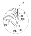
- FIG. 8 is a schematic view showing a fourth embodiment of a drop-off prevention device to which the present invention is applied.
- a dropout prevention tool 31 according to the fourth embodiment of the present invention shown in FIG. 8 includes a coil spring portion 2 in which a coil wire 2A is wound in a substantially circular shape with substantially the same diameter.
- the diameter of the coil spring portion 2 is slightly smaller than the outer diameter of the leg portion of the bolt.
- the dropout prevention tool 31 of the present invention includes the overhang portion 3 and the additional overhang portion 34.
- the overhang portion 3 has an extension coil strand 3A extending from one end of the coil strand 2A constituting the coil spring portion 2 in a winding range larger than the winding range of the coil spring portion 2, and the coil spring portion 2
- the three top portions 3C are concentrically wound in a substantially triangular shape, which is a shape that is disposed at substantially the same distance from the winding center of the coil spring portion 2.
- the overhang portion 3 is configured by winding the extended coil element wire 3 ⁇ / b> A so as to extend substantially linearly in the tangential direction outside the coil spring portion 2.
- the overhang portion 3 is a predetermined region from the tip of the extended coil strand 3A that is separated from one end of the coil strand 2A, and is separated from the coil spring portion 2 in the same direction as the direction in which the winding center of the coil spring portion 2 extends. It has an end region 3B arranged on the side.
- end region 3B is colored in a color different from the colors of the other regions, that is, the other region of the extension coil strand 3A and the region of the coil strand 2A.
- the additional overhang portion 34 has an extension coil strand 34A extending from the other end of the coil strand 2A constituting the coil spring portion 2 in a winding range larger than the winding range of the coil spring portion 2, and the coil spring portion 2
- the three top portions 34 ⁇ / b> C are wound in a substantially triangular shape, which is a shape arranged at substantially the same distance from the winding center of the coil spring portion 2.
- the additional overhang portion 34 is configured by winding an extended coil element wire 34 ⁇ / b> A extending substantially linearly in the tangential direction outside the coil spring portion 2.
- the additional overhang portion 34 is a coil spring in the same direction as the direction in which the winding center of the coil spring portion 2 extends and is a region within a predetermined range from the tip of the extended coil wire 34A that is separated from the other end of the coil strand 2A. It has an additional end region 34 ⁇ / b> B arranged on the side away from the part 2.
- the additional end region 34B is not colored.
- the overhang portion 3 colored in the end region 3B is directed toward the leg portion of the bolt. Rotate clockwise while pressing the drop-off prevention tool 31 against the leg of the bolt.
- an uncolored additional end region and a colored end region are provided, the overhanging portion where the end region is colored is directed to the leg of the bolt, and the dropout prevention device of the present invention is attached to the bolt.
- the reason for attaching to the leg is as follows.
- the fall prevention device of the present invention if the fall prevention device of the present invention is attached to the leg portion of the bolt, the fall prevention device of the present invention continues to rotate clockwise, and the colored end region is pressed against the nut and colored. The end region is pushed to the side away from the winding center of the overhanging portion, and it is easy to confirm from the outside. As a result, the user confirms that the fall-off prevention device of the present invention is firmly pressed against the nut. This is because it is easy to recognize.
- the colored region that is not pressed against the nut is also confirmed from the outside, and the user can prevent the falling of the present invention. This is because it becomes difficult to recognize that the tool is firmly pressed against the nut.
- the fall prevention tool 31 of the 4th Embodiment of this invention is a user. Since it is easy to fit the straight portion into the screw groove in the same way regardless of which of the overhanging portion 3 and the additional overhanging portion 34 is attached to the bolt, without worrying about the direction of the drop-off prevention device 31 of the present invention. Can be attached to bolts.
- the dropout prevention tool 31 of the fourth embodiment of the present invention includes the overhang portion 3 and the additional overhang portion 34 that are configured by winding the extension coil strands in a substantially triangular shape. A person can grab either one and apply rotation to the dropout prevention tool 31 of the present invention, and easily rotate the dropout prevention tool 31 of the present invention.
- FIG. 9 is a schematic plan view showing a state in which the dropout prevention device of the fourth embodiment to which the present invention is applied is mounted on a bolt and a nut.
- illustration of the to-be-fixed object is abbreviate
- the overhang portion 3 is directed to the leg portion of the bolt 4, and the drop prevention tool 31 of the present invention is attached to the bolt 4. Rotate clockwise while pressing against the leg.
- the end region 3B is pressed against the nut 5 while continuing the right rotation of the drop-off prevention tool 31 of the present invention
- the colored end region 3B is formed on the overhang portion 3 as shown in FIG. It is pushed away from the winding center and easily confirmed from the outside.
- the user can know that the drop-off prevention tool 31 of the present invention is firmly pressed against the nut 5 and can visually confirm the effect of preventing the drop-off.
- projection part 3 contacts the end surface of a nut, ie, the surface shown in FIG. 9, and the force which suppresses the left rotation of the nut 5 generate
- the end region 3B is pushed out to the side away from the winding center of the overhanging portion 3, the end region 3B tends to return to the original position, and thus a tightening force to the bolt 4 is generated.
- the drop prevention tool 31 is attached to the leg portion where the screw groove of the bolt 4 is formed, but the top portion 3C of the overhang portion 3 and the top portion 34C of the additional overhang portion 34 are not shown. Are arranged on substantially the same line in the same direction as the direction in which the winding center of the coil spring portion 2 extends.
- the top portion 3C of the overhang portion 3 and the top portion of the additional overhang portion 34 are provided.
- 34C is not disposed on the same line in the same direction as the direction in which the winding center of the coil spring portion 2 extends.
- the user can confirm not only the colored end region 3B but also the substantially hexagonal shape from the outside, it is easier to visually confirm the effect of preventing the dropout.
- extension coil wire is wound in a polygonal shape, it does not necessarily have to be wound in a substantially triangular shape.
- the extension coil wire may be wound in a substantially pentagonal shape or a substantially hexagonal shape.
- the straight portion can be fitted into the screw groove of the bolt more stably than in the case of being wound in a substantially square shape or a substantially pentagonal shape. preferable.
- the end region does not necessarily have to be colored in a color different from the color of other regions. However, it is preferable that the end region is colored in a color different from the color of other regions because the user can more easily visually confirm the effect of preventing the dropout.
- the overhanging portion and the additional overhanging portion do not necessarily have the same shape.
- the overhanging portion may have a substantially triangular shape, and the additional overhanging portion may have a substantially hexagonal shape.
- the overhanging part and the additional overhanging part have the same shape, the user can fit the straight part into the screw groove in the same way regardless of whether the overhanging part or the additional overhanging part is attached to the bolt. Since it is easy, there exists an advantage that it can mount
- the drop-off prevention device of the present invention is such that the extension coil wire extending from one end of the coil wire constituting the coil spring portion has a winding range larger than the winding range of the coil spring portion and is concentric with the coil spring portion. And a plurality of top portions are wound in a polygonal shape, which is a shape arranged at substantially the same distance from the winding center of the coil spring portion, and extending in a substantially straight line in the tangential direction of the coil spring portion. Since the projecting portion is provided, at least three straight portions of the extension coil element wire can be fitted into the screw groove of the bolt.
- the drop-off preventing device of the present invention is a region within a predetermined range from the tip of the extended coil wire separated from one end of the coil wire, and is separated from the coil spring portion in the same direction as the direction in which the winding center of the coil spring portion extends.
- the drop-off preventing device of the present invention is a region within a predetermined range from the tip of the extended coil wire separated from one end of the coil wire, and is separated from the coil spring portion in the same direction as the direction in which the winding center of the coil spring portion extends. Since the overhanging portion having the end region arranged on the side is provided, when the overhanging portion is arranged on the nut side, the end region pressed against the nut is outside the winding range of the overhanging portion, that is, Extruded to the side away from the winding center, the user can visually confirm the effect of preventing the dropout.
- the drop-off prevention device of the present invention can be easily rotated with a hand or a general-purpose tool, and can be easily attached to the bolt.
- the end region is colored in a color different from the color of other regions, the user can more easily visually confirm the effect of preventing the drop-off compared to the case where the end region is not colored.
Landscapes
- Engineering & Computer Science (AREA)
- General Engineering & Computer Science (AREA)
- Mechanical Engineering (AREA)
- Hand Tools For Fitting Together And Separating, Or Other Hand Tools (AREA)
Abstract
This falling-off prevention tool (1) is provided with a coil spring part (2) in which a coil wire (2A) is wound, and a protruding part (3). In the protruding part (3), an extension coil wire (3A) extending from one end of the coil wire (2A) constituting a part of the coil spring part (2) is wound in a substantially triangular shape so as to be coaxial with the coil spring part (2) and so that the winding range is greater than the winding range of the coil spring part (2). The protruding part (3) has an end region (3B), which is a region in a predetermined range from the tip of the extension coil wire (3A) set away from the one end of the coil wire (2A), the end region (3B) being located on the side set away from the coil spring part (2) in the same direction as that in which the winding center of the coil spring part (2) extends.
Description
本発明は脱落防止具に関する。詳しくは、ボルトから被固定物やナットが脱落することを防止する脱落防止具に係るものである。
The present invention relates to a drop-off prevention device. Specifically, the present invention relates to a drop-off prevention tool that prevents the fixed object and nut from falling off the bolt.
一般に、建築構造物を構成する二つの部材を固定するための方法として、溶接によって固定する方法や、ボルトとナットによって締結する方法が用いられている。
Generally, as a method for fixing two members constituting a building structure, a method of fixing by welding or a method of fastening by bolts and nuts is used.
また、溶接による固定は、溶接設備が必要となり、施工に手間と時間がかかり、また、固定を解除する場合も設備が必要となり、固定解除に手間と時間がかかるので、ボルトとナットによって締結する方法が多く採用されている。
In addition, fixing by welding requires welding equipment, and it takes time and labor for construction. Also, equipment is required for releasing the fixing, and it takes time and effort to release the fixing. Many methods are adopted.
しかし、ボルトとナットによって締結する方法において、ボルトやナットが振動等を受けることにより、締結後にボルトやナットが緩むことがあるため、ボルトやナットが緩んで、ボルトから被固定物やナットが脱落しないようにする発明が幾つか提案されている。
However, in the method of fastening with bolts and nuts, the bolts and nuts may loosen after fastening due to vibrations, etc., so the bolts and nuts will loosen and the to-be-fixed objects and nuts will fall off the bolts. Several inventions have been proposed to avoid this.
例えば特許文献1には、図10に示すような緩止機能付きナット401が記載されている。
すなわち、特許文献1に記載の緩止機能付きナット401は、緩止具403と、六角ナット102とで構成されている。 For example,Patent Literature 1 describes a nut 401 with a locking function as shown in FIG.
That is, thenut 401 with a locking function described in Patent Document 1 includes a locking tool 403 and a hex nut 102.
すなわち、特許文献1に記載の緩止機能付きナット401は、緩止具403と、六角ナット102とで構成されている。 For example,
That is, the
また、緩止具403は、金属線が略同一径で巻回された緩止コイル部103Aと、緩止コイル部103Aの下端から接線方向に外方に向かって、六角ナット102の外縁を越えて延伸した金属線で構成された締付自動調整部410とを有する。
The loosening stop 403 includes a loosening coil portion 103A around which a metal wire is wound with substantially the same diameter, and the outer edge of the hexagon nut 102 that extends outward in a tangential direction from the lower end of the loosening coil portion 103A. And an automatic tightening adjustment unit 410 composed of a drawn metal wire.
また、緩止具403は、緩止コイル部103Aの上端から下方に屈曲し、円環状の細溝であり六角ナット102の上面に形成された緩止具係合部430と係合可能なナット係合部420を備える。
Further, the loose fastener 403 is bent downward from the upper end of the loose coil portion 103A, is an annular narrow groove, and is a nut that can be engaged with the loose fastener engaging portion 430 formed on the upper surface of the hexagon nut 102. An engaging portion 420 is provided.
また、ナット係合部420は、緩止コイル部103Aの直径よりも大巻する部分103Bと、六角ナット102と係合する部分103Cとで構成されている。
Moreover, the nut engaging part 420 is comprised by the part 103B wound larger than the diameter of the loosening coil part 103A, and the part 103C engaged with the hexagon nut 102.
しかしながら、特許文献1に記載の緩止具は、直線部分として締付自動調整部を有しているものの、締付自動調整部はボルトのネジ溝に嵌め込まれるような構成ではないため、緩止具をボルトに装着しにくいという問題があった。
However, although the locking device described in Patent Document 1 has an automatic tightening adjustment portion as a straight portion, the automatic tightening adjustment portion is not configured to be fitted into the screw groove of the bolt. There was a problem that it was difficult to attach the tool to the bolt.
本発明は、以上の点に鑑みて創案されたものであり、ボルトへの装着を容易に行なうことができる脱落防止具を提供することを目的とする。
The present invention has been made in view of the above points, and an object thereof is to provide a drop-off preventing tool that can be easily attached to a bolt.
上記の目的を達成するために、本発明の脱落防止具は、コイル素線が略円形状に略同一径で巻回されたコイルバネ部と、該コイルバネ部を構成する前記コイル素線の一端から延びる延長コイル素線が、同コイルバネ部の巻回範囲より大きい巻回範囲で、かつ、同コイルバネ部と同心状に、かつ、複数の頂部が前記コイルバネ部の巻回中心から互いに略同一の距離に配置された形状である多角形状に、かつ、前記コイルバネ部の接線方向に略直線状に延びて巻回されており、かつ、前記コイル素線の一端から離れた前記延長コイル素線の先端から所定の範囲の領域であると共に前記コイルバネ部の巻回中心が延びる方向と同じ方向で前記コイルバネ部から離れる側に配置された端部領域を有する、張出部とを備える。
In order to achieve the above-described object, the drop-off prevention device of the present invention includes a coil spring portion in which a coil wire is wound in a substantially circular shape with substantially the same diameter, and one end of the coil wire constituting the coil spring portion. The extending extension coil wire has a winding range larger than the winding range of the coil spring portion, is concentric with the coil spring portion, and a plurality of top portions are substantially the same distance from the winding center of the coil spring portion. The tip of the extended coil wire that is wound in a polygonal shape that is a shape arranged in a straight line extending in a tangential direction of the coil spring portion and that is separated from one end of the coil wire And a projecting portion having an end region disposed on the side away from the coil spring portion in the same direction as the direction in which the winding center of the coil spring portion extends.
ここで、コイル素線が略円形状に略同一径で巻回されたコイルバネ部によって、ボルトの脚部に嵌合することができる。
Here, the coil element wire can be fitted to the leg portion of the bolt by the coil spring portion wound in a substantially circular shape with the substantially same diameter.
また、コイルバネ部を構成するコイル素線の一端から延びる延長コイル素線が、コイルバネ部の巻回範囲より大きい巻回範囲で、かつ、コイルバネ部と同心状に、かつ、複数の頂部がコイルバネ部の巻回中心から互いに略同一の距離に配置された形状である多角形状に、かつ、コイルバネ部の接線方向に略直線状に延びて巻回された張出部によって、延長コイル素線の少なくとも3箇所の直線部分をボルトのネジ溝に嵌め込むことができる。
Further, the extension coil wire extending from one end of the coil wire constituting the coil spring portion is in a winding range larger than the winding range of the coil spring portion, concentric with the coil spring portion, and a plurality of top portions are coil spring portions. At least one of the extended coil strands by an overhanging portion that is wound in a polygonal shape, which is a shape that is disposed at substantially the same distance from the winding center of the wire, and that extends substantially linearly in the tangential direction of the coil spring portion. Three straight portions can be fitted into the screw grooves of the bolt.
また、コイル素線の一端から離れた延長コイル素線の先端から所定の範囲の領域であると共にコイルバネ部の巻回中心が延びる方向と同じ方向でコイルバネ部から離れる側に配置された端部領域を有する張出部によって、このような張出部はコイルバネ部を囲むように形成されないので、延長コイル素線の少なくとも3箇所の直線部分をボルトのネジ溝に嵌め込みやすい。
Also, the end region disposed on the side away from the coil spring portion in the same direction as the direction in which the winding center of the coil spring portion extends is a region within a predetermined range from the tip of the extension coil strand separated from one end of the coil wire. Since the overhanging portion is not formed so as to surround the coil spring portion, it is easy to fit at least three straight portions of the extension coil wire into the screw groove of the bolt.
また、コイル素線の一端から離れた延長コイル素線の先端から所定の範囲の領域であると共にコイルバネ部の巻回中心が延びる方向と同じ方向でコイルバネ部から離れる側に配置された端部領域を有する張出部によって、張出部がナット側に配置された場合、ナットに押し付けられた端部領域は張出部の巻回範囲の外側すなわち巻回中心から離れる側に押し出され、使用者は、脱落防止の効果を目視で確認することができる。
Also, the end region disposed on the side away from the coil spring portion in the same direction as the direction in which the winding center of the coil spring portion extends is a region within a predetermined range from the tip of the extension coil strand separated from one end of the coil wire. When the overhanging portion is arranged on the nut side by the overhanging portion, the end region pressed against the nut is pushed outside the winding range of the overhanging portion, that is, away from the winding center, and the user Can visually confirm the effect of preventing dropout.
また、本発明の脱落防止具において、端部領域は、コイルバネ部の巻回範囲外であると共に張出部の巻回範囲内に突出して湾曲したものとすることができる。
Also, in the dropout prevention device of the present invention, the end region can be curved outside the winding range of the coil spring portion and protruding into the winding range of the overhang portion.
この場合、ナットに押し付けられた端部領域は張出部の巻回範囲の外側に押し出され、さらに張出部の端部領域以外の領域に、突出して湾曲した端部領域が当たって外側へ押し出される。そして、端部領域が当たってさらに押し出された分、端部領域には戻ろうとする力が発生し、脱落防止具に緊縮力を与えることができる。
In this case, the end region pressed against the nut is pushed outside the winding range of the overhanging portion, and further, the protruding end region hits the region other than the end region of the overhanging portion and goes outward. Extruded. Then, a force to return to the end region is generated as much as the end region hits and is pushed out, and a contraction force can be applied to the drop-off prevention device.
さらに、本発明の脱落防止具において、張出部は、延長コイル素線が略三角形状に巻回されたものとすることができる。
Furthermore, in the dropout prevention tool of the present invention, the overhanging portion can be formed by winding the extension coil wire in a substantially triangular shape.
この場合、延長コイル素線の3箇所の直線部分をボルトのネジ溝に嵌め込むことができる。
In this case, the three straight portions of the extension coil can be fitted into the bolt groove.
また、本発明の脱落防止具は、コイルバネ部を構成するコイル素線の他端から延びる延長コイル素線が、コイルバネ部の巻回範囲より大きい巻回範囲で、かつ、コイルバネ部と同心状に、かつ、複数の頂部がコイルバネ部の巻回中心から互いに略同一の距離に配置された形状である多角形状に、かつ、コイルバネ部の接線方向に略直線状に延びて巻回されており、かつ、コイル素線の他端から離れた延長コイル素線の先端から所定の範囲の領域であると共にコイルバネ部の巻回中心が延びる方向と同じ方向でコイルバネ部から離れる側に配置された追加端部領域を有する、追加張出部を備えるものとすることができる。
Further, the drop-off prevention device of the present invention is such that the extension coil strand extending from the other end of the coil strand constituting the coil spring portion is in a winding range larger than the winding range of the coil spring portion and concentrically with the coil spring portion. In addition, a plurality of top portions are wound in a polygonal shape, which is a shape that is arranged at substantially the same distance from the winding center of the coil spring portion, and extending substantially linearly in the tangential direction of the coil spring portion, And the additional end which is the area | region of the predetermined range from the front-end | tip of the extension coil strand away from the other end of the coil strand, and is arrange | positioned on the side away from a coil spring part in the same direction as the direction where the winding center of a coil spring part is extended. It may be provided with an additional overhang having a partial area.
ここで、コイルバネ部を構成するコイル素線の他端から延びる延長コイル素線がコイルバネ部の巻回範囲より大きい巻回範囲で、かつ、コイルバネ部と同心状に、かつ、複数の頂部がコイルバネ部の巻回中心から互いに略同一の距離に配置された形状である多角形状に、かつ、コイルバネ部の接線方向に略直線状に延びて巻回された追加張出部によって、使用者は、手または汎用工具で追加張出部を掴んで脱落防止具に回転を加えやすい。
Here, the extension coil strand extending from the other end of the coil strand constituting the coil spring portion is in a winding range larger than the winding range of the coil spring portion, concentrically with the coil spring portion, and a plurality of top portions are coil springs. By the additional overhanging portion wound in a polygonal shape, which is a shape arranged at substantially the same distance from the winding center of the portion, and extending substantially linearly in the tangential direction of the coil spring portion, the user can It is easy to rotate the drop-off prevention tool by grasping the additional overhanging part by hand or general-purpose tool.
また、コイル素線の他端から離れた延長コイル素線の先端から所定の範囲の領域であると共にコイルバネ部の巻回中心が延びる方向と同じ方向でコイルバネ部から離れる側に配置された追加端部領域を有する追加張出部によって、追加張出部がナット側に配置された場合、ナットに押し付けられた追加端部領域は追加張出部の巻回範囲の外側すなわち巻回中心から離れる側に押し出され、使用者は、脱落防止の効果を目視で確認することができる。
すなわち、張出部側から脱落防止具をボルトに装着しても、追加張出部側から脱落防止具をボルトに装着しても、使用者は、脱落防止の効果を目視で確認することができる。 Further, the additional end is a region within a predetermined range from the tip of the extension coil wire separated from the other end of the coil wire, and is disposed on the side away from the coil spring portion in the same direction as the direction in which the winding center of the coil spring portion extends. When the additional overhanging portion having a region is arranged on the nut side, the additional end region pressed against the nut is outside the winding range of the additional overhanging portion, that is, the side away from the winding center. The user can visually confirm the effect of preventing the dropout.
In other words, even if the fall prevention tool is attached to the bolt from the overhanging part side, or the fall prevention tool is attached to the bolt from the additional overhanging part side, the user can visually confirm the effect of the fall prevention. it can.
また、本発明の脱落防止具において、張出部は、延長コイル素線が略三角形状に巻回されており、追加張出部は、延長コイル素線が略三角形状に巻回されたものとすることができる。
In the dropout prevention device of the present invention, the extension coil wire is wound in a substantially triangular shape, and the additional extension portion is formed by winding the extension coil wire in a substantially triangular shape. It can be.
この場合、使用者は、張出部と追加張出部のどちらからボルトへ装着しても、同じように直線部分をネジ溝に嵌め込みやすいので、脱落防止具の向きを気にすることなくボルトへ装着できる。
In this case, the user can easily fit the straight part into the screw groove regardless of whether the extension part or the additional extension part is attached to the bolt. Can be attached to.
また、本発明の脱落防止具において、端部領域は、他の領域の色と異なる色に着色されたものとすることができる。
Also, in the dropout prevention device of the present invention, the end region can be colored in a color different from the color of other regions.
この場合、使用者は、脱落防止の効果を目視でさらに確認しやすい。
In this case, it is easier for the user to visually confirm the effect of preventing the dropout.
また、本発明の脱落防止具において、張出部の頂部は、張出部の略直線状の領域よりも、コイルバネ部の巻回中心が延びる方向と同じ方向でコイルバネ部から離れる側に配置されたものとすることができる。
Further, in the dropout prevention device of the present invention, the top portion of the overhanging portion is disposed on the side away from the coil spring portion in the same direction as the direction in which the winding center of the coil spring portion extends from the substantially linear region of the overhanging portion. Can be.
この場合、頂部が、ナットの傾斜した境界領域に充分に当たり、ナットの左回転を抑える力を向上させることができる。
In this case, the top portion sufficiently hits the inclined boundary region of the nut, and the force for suppressing the left rotation of the nut can be improved.
本発明に係る脱落防止具は、ボルトへの装着を容易に行なうことができる。
The drop-off prevention tool according to the present invention can be easily attached to the bolt.
以下、本発明の実施の形態について図面を参照しながら説明し、本発明の理解に供する。
図1は、本発明を適用した脱落防止具の第1の実施形態を示す概略図である。また、図2は、図1に示した本発明の脱落防止具の概略平面図である。 Hereinafter, embodiments of the present invention will be described with reference to the drawings to facilitate understanding of the present invention.
FIG. 1 is a schematic view showing a first embodiment of a drop-off prevention device to which the present invention is applied. FIG. 2 is a schematic plan view of the dropout prevention tool of the present invention shown in FIG.
図1に示す本発明の第1の実施形態の脱落防止具1は、コイル素線2Aが略円形状に略同一径で巻回されたコイルバネ部2を備える。
ここで、コイルバネ部2の径は、ボルトの脚部の外径よりもわずかに小さい。 Adropout prevention device 1 according to the first embodiment of the present invention shown in FIG. 1 includes a coil spring portion 2 in which a coil wire 2A is wound in a substantially circular shape with substantially the same diameter.
Here, the diameter of thecoil spring portion 2 is slightly smaller than the outer diameter of the leg portion of the bolt.
ここで、コイルバネ部2の径は、ボルトの脚部の外径よりもわずかに小さい。 A
Here, the diameter of the
また、本発明の脱落防止具1は、張出部3を備える。
ここで、張出部3は、コイルバネ部2を構成するコイル素線2Aの一端から延びる延長コイル素線3Aが、コイルバネ部2の巻回範囲より大きい巻回範囲で、かつ、コイルバネ部2と同心状に、かつ、3つの頂部3Cがコイルバネ部2の巻回中心から互いに略同一の距離に配置された形状である略三角形状に巻回されて構成されている。 Further, thedropout prevention device 1 of the present invention includes an overhang portion 3.
Here, theoverhang portion 3 has an extension coil strand 3A extending from one end of the coil strand 2A constituting the coil spring portion 2 in a winding range larger than the winding range of the coil spring portion 2, and the coil spring portion 2 The three top portions 3C are concentrically wound in a substantially triangular shape, which is a shape that is disposed at substantially the same distance from the winding center of the coil spring portion 2.
ここで、張出部3は、コイルバネ部2を構成するコイル素線2Aの一端から延びる延長コイル素線3Aが、コイルバネ部2の巻回範囲より大きい巻回範囲で、かつ、コイルバネ部2と同心状に、かつ、3つの頂部3Cがコイルバネ部2の巻回中心から互いに略同一の距離に配置された形状である略三角形状に巻回されて構成されている。 Further, the
Here, the
また、張出部3は、延長コイル素線3Aがコイルバネ部2の外側の接線方向に略直線状に延びて巻回されて構成されている。
すなわち、張出部3の略直線状の部分は、コイルバネ部2の外径よりも外側に位置しており、本発明の脱落防止具1のボルトの脚部への嵌合を誘い込むことができる。 Theoverhang portion 3 is formed by winding an extended coil element wire 3 </ b> A extending in a substantially straight line in the tangential direction outside the coil spring portion 2.
That is, the substantially linear portion of theoverhang portion 3 is located outside the outer diameter of the coil spring portion 2 and can invite the fitting of the drop prevention tool 1 of the present invention to the leg portion of the bolt. .
すなわち、張出部3の略直線状の部分は、コイルバネ部2の外径よりも外側に位置しており、本発明の脱落防止具1のボルトの脚部への嵌合を誘い込むことができる。 The
That is, the substantially linear portion of the
また、張出部3は、コイル素線2Aの一端から離れた延長コイル素線3Aの先端から所定の範囲の領域であると共にコイルバネ部2の巻回中心が延びる方向と同じ方向でコイルバネ部2から離れる側に配置された端部領域3Bを有する。
The overhang portion 3 is a region within a predetermined range from the tip of the extended coil strand 3A that is separated from one end of the coil strand 2A, and the coil spring portion 2 in the same direction as the direction in which the winding center of the coil spring portion 2 extends. End region 3B arranged on the side away from the center.
本明細書において、「コイルバネ部の巻回中心が延びる方向と同じ方向でコイルバネ部から離れる側に配置された」とは、すなわち、例えば図2に示すように本発明の脱落防止具1をコイルバネ部2側から、コイルバネ部2の巻回中心が延びる方向と同じ方向で見たときに、延長コイル素線3Aの他の領域の向こう側に配置されたことを意味する。
In the present specification, “disposed on the side away from the coil spring portion in the same direction as the direction in which the winding center of the coil spring portion extends” means that, for example, as shown in FIG. When viewed from the part 2 side in the same direction as the direction in which the winding center of the coil spring part 2 extends, it means that the coil spring part 2 is disposed on the other side of the other region of the extension coil strand 3A.
また、端部領域3Bは、他の領域すなわち延長コイル素線3Aの他の領域やコイル素線2Aの領域それぞれの色と異なる色、例えば赤色、緑色または黄色に着色されている。
Further, the end region 3B is colored in a color different from the colors of other regions, that is, the other regions of the extension coil strand 3A and the region of the coil strand 2A, for example, red, green, or yellow.
また、図3は、図1に示した本発明の脱落防止具を、ボルトおよびナットに装着した状態を示す概略平面図である。なお、図3において被固定物の図示を省略している。
本発明の脱落防止具1を、ボルト4のネジ溝が形成された脚部に装着する場合、張出部3をボルト4の脚部に向けて、本発明の脱落防止具1をボルト4の脚部に押し当てながら右回転させる。 FIG. 3 is a schematic plan view showing a state in which the dropout prevention device of the present invention shown in FIG. 1 is attached to a bolt and a nut. In addition, illustration of a to-be-fixed object is abbreviate | omitted in FIG.
When thedrop prevention tool 1 of the present invention is attached to the leg portion of the bolt 4 in which the thread groove is formed, the overhang portion 3 is directed to the leg portion of the bolt 4 and the drop prevention tool 1 of the present invention is attached to the bolt 4. Rotate clockwise while pressing against the leg.
本発明の脱落防止具1を、ボルト4のネジ溝が形成された脚部に装着する場合、張出部3をボルト4の脚部に向けて、本発明の脱落防止具1をボルト4の脚部に押し当てながら右回転させる。 FIG. 3 is a schematic plan view showing a state in which the dropout prevention device of the present invention shown in FIG. 1 is attached to a bolt and a nut. In addition, illustration of a to-be-fixed object is abbreviate | omitted in FIG.
When the
このとき、張出部3を構成する延長コイル素線3Aの3箇所の直線部分が、ボルト4の図示していないネジ溝に嵌り込む。
また、コイルバネ部2の張出部3側に位置するコイル素線2Aがボルト4の脚部の端部に当接する。 At this time, three linear portions of theextension coil strand 3 </ b> A constituting the overhang portion 3 are fitted into screw grooves (not shown) of the bolt 4.
Further, thecoil wire 2 </ b> A located on the projecting portion 3 side of the coil spring portion 2 abuts on the end portion of the leg portion of the bolt 4.
また、コイルバネ部2の張出部3側に位置するコイル素線2Aがボルト4の脚部の端部に当接する。 At this time, three linear portions of the
Further, the
さらに本発明の脱落防止具1の右回転を続けていくと、コイルバネ部2が誘導して、コイルバネ部2のコイル素線2Aもボルト4のネジ溝に嵌り込んでいき、速い挿入および装着ができる。
Further, if the clockwise rotation of the drop-off prevention device 1 of the present invention is continued, the coil spring portion 2 is guided, and the coil wire 2A of the coil spring portion 2 is also fitted into the thread groove of the bolt 4, so that quick insertion and mounting are possible. it can.
そして、本発明の脱落防止具1の右回転を続けていって端部領域3Bがナット5に押し付けられると、図3に示すように、着色された端部領域3Bは、張出部3の巻回範囲の外側すなわち張出部3の巻回中心から離れる側に押し出され、外部から確認されやすくなる。
その結果、使用者は、本発明の脱落防止具1がしっかりとナット5に押し付けられていることを知ることができ、脱落防止の効果を目視で確認することができる。 Then, when theend region 3B is pressed against the nut 5 while continuing the clockwise rotation of the drop-off preventing device 1 of the present invention, the colored end region 3B is formed on the overhang portion 3 as shown in FIG. It is pushed out to the outside of the winding range, that is, the side away from the winding center of the overhang portion 3, and is easily confirmed from the outside.
As a result, the user can know that the drop-off prevention tool 1 of the present invention is firmly pressed against the nut 5, and can visually confirm the effect of the drop-off prevention.
その結果、使用者は、本発明の脱落防止具1がしっかりとナット5に押し付けられていることを知ることができ、脱落防止の効果を目視で確認することができる。 Then, when the
As a result, the user can know that the drop-
また、張出部3がナット5の端面すなわち図3で示されている面に当たり、ナット5の左回転を抑える力が発生する。また、バネ効果によって常時、反作用がある。
また、端部領域3Bが張出部3の巻回中心から離れる側に押し出されていることによって、端部領域3Bが元の位置に戻ろうとするため、ボルト4への緊縮力が発生する。 Moreover, the overhang |projection part 3 hits the end surface of the nut 5, ie, the surface shown in FIG. 3, and the force which suppresses the left rotation of the nut 5 generate | occur | produces. In addition, there is always a reaction due to the spring effect.
Further, since theend region 3B is pushed out to the side away from the winding center of the overhanging portion 3, the end region 3B tends to return to the original position, and thus a tightening force to the bolt 4 is generated.
また、端部領域3Bが張出部3の巻回中心から離れる側に押し出されていることによって、端部領域3Bが元の位置に戻ろうとするため、ボルト4への緊縮力が発生する。 Moreover, the overhang |
Further, since the
図4は、本発明を適用した脱落防止具の第2の実施形態を示す概略平面図である。
なお、第2の実施形態を示す図4および図5において、第1の実施形態と同じ部材については第1の実施形態と同じ符号が付されている。 FIG. 4 is a schematic plan view showing a second embodiment of a drop-off prevention device to which the present invention is applied.
In FIGS. 4 and 5 showing the second embodiment, the same members as those in the first embodiment are denoted by the same reference numerals as those in the first embodiment.
図4に示す本発明の第2の実施形態の脱落防止具11は、張出部13を備える。
ここで、張出部13は、コイルバネ部2を構成するコイル素線2Aの一端から延びる延長コイル素線13Aが、コイルバネ部2の巻回範囲より大きい巻回範囲で、かつ、コイルバネ部2と同心状に、かつ、3つの頂部13Cがコイルバネ部2の巻回中心から互いに略同一の距離に配置された形状である略三角形状に巻回されて構成されている。 Thedropout prevention tool 11 according to the second embodiment of the present invention shown in FIG.
Here, theoverhang portion 13 has a winding range in which the extension coil strand 13A extending from one end of the coil strand 2A constituting the coil spring portion 2 is larger than the winding range of the coil spring portion 2, and the coil spring portion 2 The three top portions 13C are concentrically wound and formed in a substantially triangular shape, which is a shape that is disposed at substantially the same distance from the winding center of the coil spring portion 2.
ここで、張出部13は、コイルバネ部2を構成するコイル素線2Aの一端から延びる延長コイル素線13Aが、コイルバネ部2の巻回範囲より大きい巻回範囲で、かつ、コイルバネ部2と同心状に、かつ、3つの頂部13Cがコイルバネ部2の巻回中心から互いに略同一の距離に配置された形状である略三角形状に巻回されて構成されている。 The
Here, the
また、張出部13は、延長コイル素線13Aがコイルバネ部2の外側の接線方向に略直線状に延びて巻回されて構成されている。
Further, the overhanging portion 13 is configured by winding the extended coil element wire 13 </ b> A so as to extend substantially linearly in the tangential direction outside the coil spring portion 2.
また、張出部13は、コイル素線2Aの一端から離れた延長コイル素線13Aの先端から所定の範囲の領域であると共にコイルバネ部2の巻回中心が延びる方向と同じ方向でコイルバネ部2から離れる側に配置された端部領域13Bを有する。
The overhanging portion 13 is a region in a predetermined range from the tip of the extended coil strand 13A that is separated from one end of the coil strand 2A, and the coil spring portion 2 is in the same direction as the direction in which the winding center of the coil spring portion 2 extends. And an end region 13B disposed on the side away from the center.
また、図4に示すように、端部領域13Bは、コイルバネ部2の巻回範囲外であると共に張出部13の巻回範囲内に突出して湾曲している。
Further, as shown in FIG. 4, the end region 13 </ b> B is outside the winding range of the coil spring portion 2 and is curved to protrude into the winding range of the overhang portion 13.
また、端部領域13Bは、他の領域すなわち延長コイル素線13Aの他の領域やコイル素線2Aの領域それぞれの色と異なる色に着色されている。
Further, the end region 13B is colored in a color different from the colors of the other regions, that is, the other region of the extended coil wire 13A and the region of the coil wire 2A.
また、図5は、図4に示した本発明の脱落防止具を、ボルトおよびナットに装着した状態を示す概略平面図である。なお、図5において被固定物の図示は省略している。
FIG. 5 is a schematic plan view showing a state in which the dropout prevention device of the present invention shown in FIG. 4 is attached to a bolt and a nut. In addition, illustration of the to-be-fixed object is abbreviate | omitted in FIG.
本発明の第2の実施形態の脱落防止具11も、本発明の第1の実施形態の脱落防止具1と同様に、ボルト4の脚部に装着する場合、張出部13をボルト4の脚部に向けて、本発明の脱落防止具11をボルト4の脚部に押し当てながら右回転させる。
Similarly to the drop-off prevention tool 1 according to the first embodiment of the present invention, the drop-off prevention tool 11 according to the second embodiment of the present invention attaches the overhanging portion 13 to the bolt 4 when the bolt 4 is attached to the leg portion. The drop prevention tool 11 of the present invention is rotated rightward while pressing against the leg of the bolt 4 toward the leg.
このとき、張出部13を構成する延長コイル素線13Aの3箇所の直線部分が、ボルト4の図示していないネジ溝に嵌り込む。
また、コイルバネ部2の張出部13側に位置するコイル素線2Aがボルト4の脚部の端部に当接する。 At this time, three linear portions of the extensioncoil element wire 13 </ b> A constituting the overhang portion 13 are fitted into screw grooves (not shown) of the bolt 4.
Further, thecoil wire 2 </ b> A located on the overhanging portion 13 side of the coil spring portion 2 comes into contact with the end portion of the leg portion of the bolt 4.
また、コイルバネ部2の張出部13側に位置するコイル素線2Aがボルト4の脚部の端部に当接する。 At this time, three linear portions of the extension
Further, the
さらに本発明の脱落防止具11の右回転を続けていって端部領域13Bがナット5に押し付けられると、図5に示すように、着色された端部領域13Bは、張出部13の巻回範囲の外側すなわち張出部13の巻回中心から離れる側に押し出され、外部から確認されやすくなる。
その結果、使用者は、本発明の脱落防止具11がしっかりとナット5に押し付けられていることを知ることができ、脱落防止の効果を目視で確認することができる。 When theend region 13B is pressed against the nut 5 while continuing the clockwise rotation of the drop-off preventing tool 11 of the present invention, the colored end region 13B is wound on the overhanging portion 13 as shown in FIG. It is pushed out to the outside of the turning range, that is, the side away from the winding center of the overhanging portion 13, and is easily confirmed from the outside.
As a result, the user can know that the drop-off prevention tool 11 of the present invention is firmly pressed against the nut 5, and can visually confirm the effect of the drop-off prevention.
その結果、使用者は、本発明の脱落防止具11がしっかりとナット5に押し付けられていることを知ることができ、脱落防止の効果を目視で確認することができる。 When the
As a result, the user can know that the drop-
さらに、本発明の第2の実施形態の脱落防止具11は、端部領域13Bが、コイルバネ部2の巻回範囲外であると共に張出部13の巻回範囲内に突出して湾曲しているので、さらに張出部13の端部領域以外の領域に、突出して湾曲した端部領域13Bが当たって外側へ押し出される。
そして、張出部13の端部領域以外の領域に端部領域13Bが当たってさらに押し出された分、端部領域13Bには戻ろうとする力が発生し、本発明の脱落防止具11に緊縮力を与えることができる。 Furthermore, in the drop-off prevention device 11 of the second embodiment of the present invention, the end region 13B is curved outside the winding range of the coil spring portion 2 and protruding into the winding range of the overhang portion 13. Therefore, the projected and curved end region 13B hits a region other than the end region of the overhang 13 and is pushed outward.
Then, as theend region 13B hits the region other than the end region of the overhang portion 13 and is further pushed out, a force to return to the end region 13B is generated, and the fall prevention tool 11 of the present invention is contracted. Can give power.
そして、張出部13の端部領域以外の領域に端部領域13Bが当たってさらに押し出された分、端部領域13Bには戻ろうとする力が発生し、本発明の脱落防止具11に緊縮力を与えることができる。 Furthermore, in the drop-
Then, as the
また、湾曲した端部領域13Bの湾曲の大きさを変えることで、張出部13の端部領域以外の領域に端部領域13Bが当たってさらに押し出された際に端部領域13Bに発生する、戻ろうとする力の大きさを変えることができる。
Moreover, by changing the magnitude of the curvature of the curved end region 13B, it occurs in the end region 13B when the end region 13B hits a region other than the end region of the overhanging portion 13 and is further pushed out. , You can change the magnitude of the force to return.
図6は、本発明を適用した第2の実施形態の脱落防止具の変形例を示す概略部分拡大図である。
図6に示すように、頂部13Cを中心とした両側の一定領域が、傾斜部13Dを設けることによって、それ以外の領域すなわち延長コイル素線13Aの略直線状の領域よりも、コイルバネ部2の巻回中心が延びる方向と同じ方向においてコイルバネ部2から離れた側に位置している。
すなわち、頂部13Cを中心とした両側の一定領域が、図6において下方に傾斜している。 FIG. 6 is a schematic partially enlarged view showing a modified example of the dropout prevention tool of the second embodiment to which the present invention is applied.
As shown in FIG. 6, the fixed regions on both sides centered on thetop portion 13 </ b> C are provided with the inclined portions 13 </ b> D, so that the coil spring portion 2 has a larger area than the other regions, i. It is located on the side away from the coil spring portion 2 in the same direction as the direction in which the winding center extends.
That is, certain regions on both sides centering on thetop portion 13C are inclined downward in FIG.
図6に示すように、頂部13Cを中心とした両側の一定領域が、傾斜部13Dを設けることによって、それ以外の領域すなわち延長コイル素線13Aの略直線状の領域よりも、コイルバネ部2の巻回中心が延びる方向と同じ方向においてコイルバネ部2から離れた側に位置している。
すなわち、頂部13Cを中心とした両側の一定領域が、図6において下方に傾斜している。 FIG. 6 is a schematic partially enlarged view showing a modified example of the dropout prevention tool of the second embodiment to which the present invention is applied.
As shown in FIG. 6, the fixed regions on both sides centered on the
That is, certain regions on both sides centering on the
また、3箇所の頂部13Cそれぞれを中心とした両側の一定領域をこのような構成にすることによって、この一定領域がナットに充分に当たり、ナットの左回転を抑える力を向上させることができる。
Further, by configuring the constant regions on both sides centering on each of the three top portions 13C as described above, this constant region sufficiently hits the nut, and the force for suppressing the left rotation of the nut can be improved.
すなわち、一般的に、ナットの端面と、ナットの端面に対して略直交する側面とが互いに接する境界領域は、図6に示すように頂部13Cを中心とした両側の一定領域を、延長コイル素線13Aの略直線状の領域よりも、コイルバネ部2の巻回中心が延びる方向と同じ方向においてコイルバネ部2から離れた側に位置させることによって、頂部13Cを中心とした両側の一定領域が、ナットの傾斜した境界領域に充分に当たり、ナットの左回転を抑える力を向上させることができる。
なお、図面ではナットの境界領域の傾斜は図示を省略している。 That is, generally, the boundary region where the end surface of the nut and the side surface substantially orthogonal to the end surface of the nut are in contact with each other is a fixed region on both sides centered on thetop portion 13C as shown in FIG. By positioning on the side away from the coil spring part 2 in the same direction as the direction in which the winding center of the coil spring part 2 extends rather than the substantially linear area of the line 13A, the constant areas on both sides centering on the top part 13C are It is possible to improve the force that sufficiently hits the inclined boundary region of the nut and suppresses the left rotation of the nut.
In the drawings, the inclination of the boundary region of the nut is not shown.
なお、図面ではナットの境界領域の傾斜は図示を省略している。 That is, generally, the boundary region where the end surface of the nut and the side surface substantially orthogonal to the end surface of the nut are in contact with each other is a fixed region on both sides centered on the
In the drawings, the inclination of the boundary region of the nut is not shown.
図7は、本発明を適用した第3の実施形態の脱落防止具を、ボルトおよびナットに装着した状態を示す概略平面図である。
なお、第3の実施形態を示す図7において、第1の実施形態と同じ部材については第1の実施形態と同じ符号が付されている。
また、図7において被固定物の図示は省略している。 FIG. 7 is a schematic plan view showing a state in which the dropout prevention tool of the third embodiment to which the present invention is applied is mounted on a bolt and a nut.
In FIG. 7 showing the third embodiment, the same members as those in the first embodiment are denoted by the same reference numerals as those in the first embodiment.
Further, in FIG. 7, the illustration of the fixed object is omitted.
図7に示す本発明の第3の実施形態の脱落防止具21は、張出部23を備える。
ここで、張出部23は、コイルバネ部2を構成するコイル素線2Aの一端から延びる延長コイル素線23Aが、コイルバネ部2の巻回範囲より大きい巻回範囲で、かつ、コイルバネ部2と同心状に、かつ、3つの頂部23Cがコイルバネ部2の巻回中心から互いに略同一の距離に配置された形状である略三角形状に巻回されていると共に、さらにもう1つの頂部23Cを形成するよう巻回されて構成されている。 Adropout prevention tool 21 according to the third embodiment of the present invention shown in FIG.
Here, theoverhang portion 23 has an extension coil strand 23A extending from one end of the coil strand 2A constituting the coil spring portion 2 in a winding range larger than the winding range of the coil spring portion 2, and the coil spring portion 2 The three top portions 23C are concentrically wound in a substantially triangular shape that is disposed at substantially the same distance from the winding center of the coil spring portion 2, and further, another top portion 23C is formed. It is configured to be wound.
ここで、張出部23は、コイルバネ部2を構成するコイル素線2Aの一端から延びる延長コイル素線23Aが、コイルバネ部2の巻回範囲より大きい巻回範囲で、かつ、コイルバネ部2と同心状に、かつ、3つの頂部23Cがコイルバネ部2の巻回中心から互いに略同一の距離に配置された形状である略三角形状に巻回されていると共に、さらにもう1つの頂部23Cを形成するよう巻回されて構成されている。 A
Here, the
また、張出部23は、延長コイル素線23Aが2箇所においてコイルバネ部2の外側の接線方向に略直線状に延びて巻回されて構成されている。
Further, the overhang portion 23 is configured by extending the extended coil wire 23 </ b> A so as to extend substantially linearly in the tangential direction outside the coil spring portion 2 at two locations.
また、張出部23は、コイル素線2Aの一端から離れた延長コイル素線23Aの先端から所定の範囲の領域であると共にコイルバネ部2の巻回中心が延びる方向と同じ方向でコイルバネ部2から離れる側に配置された端部領域23Bを有する。
Further, the overhang portion 23 is a region in a predetermined range from the tip of the extended coil strand 23A that is separated from one end of the coil strand 2A, and is in the same direction as the direction in which the winding center of the coil spring portion 2 extends. End portion 23B disposed on the side away from the center.
また、端部領域23Bは、他の領域すなわち延長コイル素線23Aの他の領域やコイル素線2Aの領域それぞれの色と異なる色に着色されている。
Further, the end region 23B is colored in a color different from the colors of the other regions, that is, the other region of the extension coil wire 23A and the region of the coil wire 2A.
本発明の第3の実施形態の脱落防止具21も、本発明の第1の実施形態の脱落防止具1と同様に、ボルト4の脚部に装着する場合、張出部23をボルト4の脚部に向けて、本発明の脱落防止具21をボルト4の脚部に押し当てながら右回転させる。
Similarly to the dropout prevention device 1 of the first embodiment of the present invention, the dropout prevention device 21 of the third embodiment of the present invention is attached to the leg portion of the bolt 4, and the overhang portion 23 is attached to the bolt 4. The drop prevention tool 21 of the present invention is rotated to the right while being pressed against the leg of the bolt 4 toward the leg.
このとき、張出部23を構成する延長コイル素線23Aの2箇所の直線部分が、ボルト4の図示していないネジ溝に嵌り込む。
また、コイルバネ部2の張出部23側に位置するコイル素線2Aがボルト4の脚部の端部に当接する。 At this time, two linear portions of theextension coil strand 23 </ b> A constituting the overhang portion 23 are fitted into a screw groove (not shown) of the bolt 4.
Further, thecoil wire 2 </ b> A located on the overhanging portion 23 side of the coil spring portion 2 comes into contact with the end portion of the leg portion of the bolt 4.
また、コイルバネ部2の張出部23側に位置するコイル素線2Aがボルト4の脚部の端部に当接する。 At this time, two linear portions of the
Further, the
さらに本発明の脱落防止具21の右回転を続けていって端部領域23Bがナット5に押し付けられると、図7に示すように、着色された端部領域23Bは、張出部23の巻回範囲のうちコイル素線2Aの一端から数えて3番目の頂部23Cまでの巻回範囲の外側すなわち張出部23の巻回中心から離れる側に押し出され、外部から確認されやすくなる。
その結果、使用者は、本発明の脱落防止具21がしっかりとナット5に押し付けられていることを知ることができ、脱落防止の効果を目視で確認することができる。 When theend region 23B is pressed against the nut 5 while continuing the clockwise rotation of the drop-off preventing device 21 of the present invention, the colored end region 23B is wound on the overhang portion 23 as shown in FIG. It is pushed out of the winding range from the one end of the coil wire 2A to the third top 23C in the winding range, that is, the side away from the winding center of the overhang 23, and is easily confirmed from the outside.
As a result, the user can know that the drop-off prevention tool 21 of the present invention is firmly pressed against the nut 5, and can visually confirm the effect of the drop-off prevention.
その結果、使用者は、本発明の脱落防止具21がしっかりとナット5に押し付けられていることを知ることができ、脱落防止の効果を目視で確認することができる。 When the
As a result, the user can know that the drop-
図8は、本発明を適用した脱落防止具の第4の実施形態を示す概略図である。
図8に示す本発明の第4の実施形態の脱落防止具31は、コイル素線2Aが略円形状に略同一径で巻回されたコイルバネ部2を備える。
ここで、コイルバネ部2の径は、ボルトの脚部の外径よりもわずかに小さい。 FIG. 8 is a schematic view showing a fourth embodiment of a drop-off prevention device to which the present invention is applied.
Adropout prevention tool 31 according to the fourth embodiment of the present invention shown in FIG. 8 includes a coil spring portion 2 in which a coil wire 2A is wound in a substantially circular shape with substantially the same diameter.
Here, the diameter of thecoil spring portion 2 is slightly smaller than the outer diameter of the leg portion of the bolt.
図8に示す本発明の第4の実施形態の脱落防止具31は、コイル素線2Aが略円形状に略同一径で巻回されたコイルバネ部2を備える。
ここで、コイルバネ部2の径は、ボルトの脚部の外径よりもわずかに小さい。 FIG. 8 is a schematic view showing a fourth embodiment of a drop-off prevention device to which the present invention is applied.
A
Here, the diameter of the
また、本発明の脱落防止具31は、張出部3と追加張出部34を備える。
ここで、張出部3は、コイルバネ部2を構成するコイル素線2Aの一端から延びる延長コイル素線3Aが、コイルバネ部2の巻回範囲より大きい巻回範囲で、かつ、コイルバネ部2と同心状に、かつ、3つの頂部3Cがコイルバネ部2の巻回中心から互いに略同一の距離に配置された形状である略三角形状に巻回されて構成されている。 Further, thedropout prevention tool 31 of the present invention includes the overhang portion 3 and the additional overhang portion 34.
Here, theoverhang portion 3 has an extension coil strand 3A extending from one end of the coil strand 2A constituting the coil spring portion 2 in a winding range larger than the winding range of the coil spring portion 2, and the coil spring portion 2 The three top portions 3C are concentrically wound in a substantially triangular shape, which is a shape that is disposed at substantially the same distance from the winding center of the coil spring portion 2.
ここで、張出部3は、コイルバネ部2を構成するコイル素線2Aの一端から延びる延長コイル素線3Aが、コイルバネ部2の巻回範囲より大きい巻回範囲で、かつ、コイルバネ部2と同心状に、かつ、3つの頂部3Cがコイルバネ部2の巻回中心から互いに略同一の距離に配置された形状である略三角形状に巻回されて構成されている。 Further, the
Here, the
また、張出部3は、延長コイル素線3Aがコイルバネ部2の外側の接線方向に略直線状に延びて巻回されて構成されている。
Further, the overhang portion 3 is configured by winding the extended coil element wire 3 </ b> A so as to extend substantially linearly in the tangential direction outside the coil spring portion 2.
また、張出部3は、コイル素線2Aの一端から離れた延長コイル素線3Aの先端から所定の領域であると共にコイルバネ部2の巻回中心が延びる方向と同じ方向でコイルバネ部2から離れる側に配置された端部領域3Bを有する。
The overhang portion 3 is a predetermined region from the tip of the extended coil strand 3A that is separated from one end of the coil strand 2A, and is separated from the coil spring portion 2 in the same direction as the direction in which the winding center of the coil spring portion 2 extends. It has an end region 3B arranged on the side.
また、端部領域3Bは、他の領域すなわち延長コイル素線3Aの他の領域やコイル素線2Aの領域それぞれの色と異なる色に着色されている。
Further, the end region 3B is colored in a color different from the colors of the other regions, that is, the other region of the extension coil strand 3A and the region of the coil strand 2A.
また、追加張出部34は、コイルバネ部2を構成するコイル素線2Aの他端から延びる延長コイル素線34Aが、コイルバネ部2の巻回範囲より大きい巻回範囲で、かつ、コイルバネ部2と同心状に、かつ、3つの頂部34Cがコイルバネ部2の巻回中心から互いに略同一の距離に配置された形状である略三角形状に巻回されて構成されている。
Further, the additional overhang portion 34 has an extension coil strand 34A extending from the other end of the coil strand 2A constituting the coil spring portion 2 in a winding range larger than the winding range of the coil spring portion 2, and the coil spring portion 2 The three top portions 34 </ b> C are wound in a substantially triangular shape, which is a shape arranged at substantially the same distance from the winding center of the coil spring portion 2.
また、追加張出部34は、延長コイル素線34Aがコイルバネ部2の外側の接線方向に略直線状に延びて巻回されて構成されている。
Further, the additional overhang portion 34 is configured by winding an extended coil element wire 34 </ b> A extending substantially linearly in the tangential direction outside the coil spring portion 2.
また、追加張出部34は、コイル素線2Aの他端から離れた延長コイル素線34Aの先端から所定の範囲の領域であると共にコイルバネ部2の巻回中心が延びる方向と同じ方向でコイルバネ部2から離れる側に配置された追加端部領域34Bを有する。
Further, the additional overhang portion 34 is a coil spring in the same direction as the direction in which the winding center of the coil spring portion 2 extends and is a region within a predetermined range from the tip of the extended coil wire 34A that is separated from the other end of the coil strand 2A. It has an additional end region 34 </ b> B arranged on the side away from the part 2.
また、追加端部領域34Bは、端部領域3Bとは異なり、着色されていない。
Further, unlike the end region 3B, the additional end region 34B is not colored.
また、本発明の脱落防止具31を、ボルトのネジ溝が形成された脚部に装着する場合、端部領域3Bが着色されている張出部3をボルトの脚部に向けて、本発明の脱落防止具31をボルトの脚部に押し当てながら右回転させる。
In addition, when the drop prevention tool 31 of the present invention is attached to a leg portion in which a screw groove of a bolt is formed, the overhang portion 3 colored in the end region 3B is directed toward the leg portion of the bolt. Rotate clockwise while pressing the drop-off prevention tool 31 against the leg of the bolt.
ここで、着色されていない追加端部領域と着色された端部領域とを設け、端部領域が着色されている張出部をボルトの脚部に向けて本発明の脱落防止具をボルトの脚部に装着する理由は次のとおりである。
Here, an uncolored additional end region and a colored end region are provided, the overhanging portion where the end region is colored is directed to the leg of the bolt, and the dropout prevention device of the present invention is attached to the bolt. The reason for attaching to the leg is as follows.
このように本発明の脱落防止具をボルトの脚部に装着すれば、本発明の脱落防止具の右回転を続けていって、着色された端部領域がナットに押し当てられ、着色された端部領域が張出部の巻回中心から離れる側に押し出されて、外部から確認されやすくなり、その結果、使用者は、本発明の脱落防止具がしっかりとナットに押し付けられていることを認識しやすいからである。
Thus, if the fall prevention device of the present invention is attached to the leg portion of the bolt, the fall prevention device of the present invention continues to rotate clockwise, and the colored end region is pressed against the nut and colored. The end region is pushed to the side away from the winding center of the overhanging portion, and it is easy to confirm from the outside. As a result, the user confirms that the fall-off prevention device of the present invention is firmly pressed against the nut. This is because it is easy to recognize.
また、端部領域と追加端部領域の両方が着色されていると、ナットに押し当てられていない方の着色領域も外部から確認されることになり、かえって使用者は、本発明の脱落防止具がしっかりとナットに押し付けられていることを認識し難くなるからである。
In addition, when both the end region and the additional end region are colored, the colored region that is not pressed against the nut is also confirmed from the outside, and the user can prevent the falling of the present invention. This is because it becomes difficult to recognize that the tool is firmly pressed against the nut.
また、本発明の第4の実施形態の脱落防止具31は、張出部3と追加張出部34がどちらも延長コイル素線を略三角形状に巻回して構成されているので、使用者は、張出部3と追加張出部34のどちらからボルトへ装着しても、同じように直線部分をネジ溝に嵌め込みやすいため、本発明の脱落防止具31の向きを気にすることなくボルトへ装着することができる。
Moreover, since the overhang | projection part 3 and the additional overhang | projection part 34 are both comprised by winding the extension coil strand in the substantially triangular shape, the fall prevention tool 31 of the 4th Embodiment of this invention is a user. Since it is easy to fit the straight portion into the screw groove in the same way regardless of which of the overhanging portion 3 and the additional overhanging portion 34 is attached to the bolt, without worrying about the direction of the drop-off prevention device 31 of the present invention. Can be attached to bolts.
また、本発明の第4の実施形態の脱落防止具31は、延長コイル素線が略三角形状に巻回されて構成された張出部3と追加張出部34を備えているので、使用者は、どちらか一方を掴んで本発明の脱落防止具31に回転を加えることができ、本発明の脱落防止具31を回転させやすい。
Further, the dropout prevention tool 31 of the fourth embodiment of the present invention includes the overhang portion 3 and the additional overhang portion 34 that are configured by winding the extension coil strands in a substantially triangular shape. A person can grab either one and apply rotation to the dropout prevention tool 31 of the present invention, and easily rotate the dropout prevention tool 31 of the present invention.
図9は、本発明を適用した第4の実施形態の脱落防止具を、ボルトおよびナットに装着した状態を示す概略平面図である。なお、図9において被固定物の図示は省略している。
FIG. 9 is a schematic plan view showing a state in which the dropout prevention device of the fourth embodiment to which the present invention is applied is mounted on a bolt and a nut. In addition, illustration of the to-be-fixed object is abbreviate | omitted in FIG.
本発明の脱落防止具31を、ボルト4のネジ溝が形成された脚部に装着する場合、張出部3をボルト4の脚部に向けて、本発明の脱落防止具31をボルト4の脚部に押し当てながら右回転させる。
When the drop prevention tool 31 of the present invention is attached to the leg portion of the bolt 4 in which the thread groove is formed, the overhang portion 3 is directed to the leg portion of the bolt 4, and the drop prevention tool 31 of the present invention is attached to the bolt 4. Rotate clockwise while pressing against the leg.
そして、本発明の脱落防止具31の右回転を続けていって端部領域3Bがナット5に押し付けられると、図9に示すように、着色された端部領域3Bは、張出部3の巻回中心から離れる側に押し出され、外部から確認されやすくなる。
その結果、使用者は、本発明の脱落防止具31がしっかりとナット5に押し付けられていることを知ることができ、脱落防止の効果を目視で確認することができる。 Then, when theend region 3B is pressed against the nut 5 while continuing the right rotation of the drop-off prevention tool 31 of the present invention, the colored end region 3B is formed on the overhang portion 3 as shown in FIG. It is pushed away from the winding center and easily confirmed from the outside.
As a result, the user can know that the drop-off prevention tool 31 of the present invention is firmly pressed against the nut 5 and can visually confirm the effect of preventing the drop-off.
その結果、使用者は、本発明の脱落防止具31がしっかりとナット5に押し付けられていることを知ることができ、脱落防止の効果を目視で確認することができる。 Then, when the
As a result, the user can know that the drop-
また、張出部3がナットの端面すなわち図9で示されている面に当たり、ナット5の左回転を抑える力が発生する。また、バネ効果によって常時、反作用がある。
また、端部領域3Bが張出部3の巻回中心から離れる側に押し出されていることによって、端部領域3Bが元の位置に戻ろうとするため、ボルト4への緊縮力が発生する。 Moreover, the overhang |projection part 3 contacts the end surface of a nut, ie, the surface shown in FIG. 9, and the force which suppresses the left rotation of the nut 5 generate | occur | produces. In addition, there is always a reaction due to the spring effect.
Further, since theend region 3B is pushed out to the side away from the winding center of the overhanging portion 3, the end region 3B tends to return to the original position, and thus a tightening force to the bolt 4 is generated.
また、端部領域3Bが張出部3の巻回中心から離れる側に押し出されていることによって、端部領域3Bが元の位置に戻ろうとするため、ボルト4への緊縮力が発生する。 Moreover, the overhang |
Further, since the
また、本発明の脱落防止具31を、ボルト4のネジ溝が形成された脚部に装着する前は、図示していないが、張出部3の頂部3Cと追加張出部34の頂部34Cは、コイルバネ部2の巻回中心が延びる方向と同じ方向において略同一線上に配置されている。
Although not shown, the drop prevention tool 31 according to the present invention is attached to the leg portion where the screw groove of the bolt 4 is formed, but the top portion 3C of the overhang portion 3 and the top portion 34C of the additional overhang portion 34 are not shown. Are arranged on substantially the same line in the same direction as the direction in which the winding center of the coil spring portion 2 extends.
一方、本発明の脱落防止具31を、ボルト4のネジ溝が形成された脚部に装着した後は、図9に示すように、張出部3の頂部3Cと追加張出部34の頂部34Cは、コイルバネ部2の巻回中心が延びる方向と同じ方向において同一線上には配置されなくなる。
On the other hand, after the drop prevention tool 31 of the present invention is attached to the leg portion where the screw groove of the bolt 4 is formed, as shown in FIG. 9, the top portion 3C of the overhang portion 3 and the top portion of the additional overhang portion 34 are provided. 34C is not disposed on the same line in the same direction as the direction in which the winding center of the coil spring portion 2 extends.
このとき、本発明の脱落防止具31を追加張出部34側から、コイルバネ部2の巻回中心が延びる方向と同じ方向で見ると、図9に示すように略六角形に見え、すべての頂部3Cと頂部34Cを目視できる。
At this time, when the drop-off prevention tool 31 of the present invention is viewed from the side of the additional overhang portion 34 in the same direction as the direction in which the winding center of the coil spring portion 2 extends, it looks almost hexagonal as shown in FIG. The top 3C and the top 34C are visible.
すなわち、使用者は、着色された端部領域3Bのみならず、略六角形の形状を外部から確認できるので、より一層、脱落防止の効果を目視で確認しやすい。
That is, since the user can confirm not only the colored end region 3B but also the substantially hexagonal shape from the outside, it is easier to visually confirm the effect of preventing the dropout.
また、延長コイル素線が多角形状に巻回されていれば、必ずしも略三角形状に巻回されていなくてもよい。例えば、延長コイル素線は略五角形状もしくは略六角形状に巻回されていてもよい。
In addition, as long as the extension coil wire is wound in a polygonal shape, it does not necessarily have to be wound in a substantially triangular shape. For example, the extension coil wire may be wound in a substantially pentagonal shape or a substantially hexagonal shape.
しかし、延長コイル素線が略三角形状に巻回されていれば、略四角形状もしくは略五角形状に巻回された場合よりも安定して直線部分をボルトのネジ溝に嵌め込むことができるので好ましい。
However, if the extension coil wire is wound in a substantially triangular shape, the straight portion can be fitted into the screw groove of the bolt more stably than in the case of being wound in a substantially square shape or a substantially pentagonal shape. preferable.
また、必ずしも端部領域は、他の領域の色と異なる色に着色されていなくてもよい。
しかし、端部領域が、他の領域の色と異なる色に着色されていれば、使用者は脱落防止の効果を目視でさらに確認しやすくなるので好ましい。 In addition, the end region does not necessarily have to be colored in a color different from the color of other regions.
However, it is preferable that the end region is colored in a color different from the color of other regions because the user can more easily visually confirm the effect of preventing the dropout.
また、必ずしも張出部と追加張出部が互いに同じ形状になっていなくてもよい。例えば、張出部は略三角形状であり、追加張出部は略六角形状とすることができる。
Also, the overhanging portion and the additional overhanging portion do not necessarily have the same shape. For example, the overhanging portion may have a substantially triangular shape, and the additional overhanging portion may have a substantially hexagonal shape.
ただし、張出部と追加張出部が互いに同じ形状であれば、使用者は、張出部と追加張出部のどちらからボルトへ装着しても、同じように直線部分をネジ溝に嵌め込みやすいため、本発明の脱落防止具の向きを気にすることなくボルトへ装着することができるという利点がある。
However, if the overhanging part and the additional overhanging part have the same shape, the user can fit the straight part into the screw groove in the same way regardless of whether the overhanging part or the additional overhanging part is attached to the bolt. Since it is easy, there exists an advantage that it can mount | wear to a volt | bolt, without minding the direction of the drop-off prevention tool of this invention.
以上のように、本発明の脱落防止具は、コイルバネ部を構成するコイル素線の一端から延びる延長コイル素線が、コイルバネ部の巻回範囲より大きい巻回範囲で、かつ、コイルバネ部と同心状に、かつ、複数の頂部がコイルバネ部の巻回中心から互いに略同一の距離に配置された形状である多角形状に、かつ、コイルバネ部の接線方向に略直線状に延びて巻回された張出部を備えているので、延長コイル素線の少なくとも3箇所の直線部分をボルトのネジ溝に嵌め込むことができる。
As described above, the drop-off prevention device of the present invention is such that the extension coil wire extending from one end of the coil wire constituting the coil spring portion has a winding range larger than the winding range of the coil spring portion and is concentric with the coil spring portion. And a plurality of top portions are wound in a polygonal shape, which is a shape arranged at substantially the same distance from the winding center of the coil spring portion, and extending in a substantially straight line in the tangential direction of the coil spring portion. Since the projecting portion is provided, at least three straight portions of the extension coil element wire can be fitted into the screw groove of the bolt.
また、本発明の脱落防止具は、コイル素線の一端から離れた延長コイル素線の先端から所定の範囲の領域であると共にコイルバネ部の巻回中心が延びる方向と同じ方向でコイルバネ部から離れる側に配置された端部領域を有する張出部を備えており、このような張出部はコイルバネ部を囲むように形成されないので、延長コイル素線の少なくとも3箇所の直線部分をボルトのネジ溝に嵌め込みやすい。
In addition, the drop-off preventing device of the present invention is a region within a predetermined range from the tip of the extended coil wire separated from one end of the coil wire, and is separated from the coil spring portion in the same direction as the direction in which the winding center of the coil spring portion extends. A projecting portion having an end region disposed on the side, and since such a projecting portion is not formed so as to surround the coil spring portion, at least three straight portions of the extension coil element wire are screwed Easy to fit in the groove.
また、本発明の脱落防止具は、コイル素線の一端から離れた延長コイル素線の先端から所定の範囲の領域であると共にコイルバネ部の巻回中心が延びる方向と同じ方向でコイルバネ部から離れる側に配置された端部領域を有する張出部を備えているので、張出部がナット側に配置された場合、ナットに押し付けられた端部領域は張出部の巻回範囲の外側すなわち巻回中心から離れる側に押し出され、使用者は、脱落防止の効果を目視で確認することができる。
In addition, the drop-off preventing device of the present invention is a region within a predetermined range from the tip of the extended coil wire separated from one end of the coil wire, and is separated from the coil spring portion in the same direction as the direction in which the winding center of the coil spring portion extends. Since the overhanging portion having the end region arranged on the side is provided, when the overhanging portion is arranged on the nut side, the end region pressed against the nut is outside the winding range of the overhanging portion, that is, Extruded to the side away from the winding center, the user can visually confirm the effect of preventing the dropout.
従って、本発明の脱落防止具は、手や汎用工具で簡単に回転させられることができ、ボルトへの装着を容易に行なうことができる。
Therefore, the drop-off prevention device of the present invention can be easily rotated with a hand or a general-purpose tool, and can be easily attached to the bolt.
また、特に端部領域が他の領域の色と異なる色に着色されているので、使用者は、着色されていない場合に比べて脱落防止の効果を目視でさらに確認しやすい。
Also, since the end region is colored in a color different from the color of other regions, the user can more easily visually confirm the effect of preventing the drop-off compared to the case where the end region is not colored.
1 脱落防止具
2 コイルバネ部
2A コイル素線
3 張出部
3A 延長コイル素線
3B 端部領域
3C 頂部
4 ボルト
5 ナット
11 脱落防止具
13 張出部
13A 延長コイル素線
13B 湾曲端部領域
13C 頂部
13D 傾斜部
21 脱落防止具
23 張出部
23A 延長コイル素線
23B 端部領域
23C 頂部
31 脱落防止具
33 張出部
34 追加張出部
34A 延長コイル素線
34B 追加端部領域
34C 追加頂部 DESCRIPTION OFSYMBOLS 1 Drop-off prevention tool 2 Coil spring part 2A Coil strand 3 Overhang | projection part 3A Extension coil strand 3B End area | region 3C Top part 4 Bolt 5 Nut 11 Fall-off prevention tool 13 Overhang | projection part 13A Extension coil element | wire 13B Curved end area | region 13C Top part 13D Inclined part 21 Fallout prevention tool 23 Overhang part 23A Extension coil element wire 23B End area 23C Top part 31 Fallout prevention tool 33 Overhang part 34 Additional overhang part 34A Extension coil element wire 34B Additional end part area 34C Additional top part
2 コイルバネ部
2A コイル素線
3 張出部
3A 延長コイル素線
3B 端部領域
3C 頂部
4 ボルト
5 ナット
11 脱落防止具
13 張出部
13A 延長コイル素線
13B 湾曲端部領域
13C 頂部
13D 傾斜部
21 脱落防止具
23 張出部
23A 延長コイル素線
23B 端部領域
23C 頂部
31 脱落防止具
33 張出部
34 追加張出部
34A 延長コイル素線
34B 追加端部領域
34C 追加頂部 DESCRIPTION OF
Claims (7)
- コイル素線が略円形状に略同一径で巻回されたコイルバネ部と、
該コイルバネ部を構成する前記コイル素線の一端から延びる延長コイル素線が、同コイルバネ部の巻回範囲より大きい巻回範囲で、かつ、同コイルバネ部と同心状に、かつ、複数の頂部が前記コイルバネ部の巻回中心から互いに略同一の距離に配置された形状である多角形状に、かつ、前記コイルバネ部の接線方向に略直線状に延びて巻回されており、かつ、前記コイル素線の一端から離れた前記延長コイル素線の先端から所定の範囲の領域であると共に前記コイルバネ部の巻回中心が延びる方向と同じ方向で前記コイルバネ部から離れる側に配置された端部領域を有する、張出部とを備える
脱落防止具。 A coil spring portion in which a coil wire is wound in a substantially circular shape with substantially the same diameter;
The extension coil wire extending from one end of the coil wire constituting the coil spring portion has a winding range larger than the winding range of the coil spring portion, is concentric with the coil spring portion, and has a plurality of top portions. The coil spring portion is wound in a polygonal shape, which is a shape disposed at substantially the same distance from the winding center of the coil spring portion, extending in a substantially tangential direction of the coil spring portion, and the coil element An end region disposed on the side away from the coil spring portion in the same direction as the direction in which the winding center of the coil spring portion extends, and is a region within a predetermined range from the tip of the extension coil strand separated from one end of the wire. A drop-off prevention device comprising an overhanging portion. - 前記端部領域は、前記コイルバネ部の巻回範囲外であると共に前記張出部の巻回範囲内に突出して湾曲した
請求項1に記載の脱落防止具。 The dropout prevention tool according to claim 1, wherein the end region is curved outside the winding range of the coil spring portion and projecting into the winding range of the overhang portion. - 前記張出部は、前記延長コイル素線が略三角形状に巻回された
請求項1に記載の脱落防止具。 The dropout prevention tool according to claim 1, wherein the extension coil strand is wound in a substantially triangular shape. - 前記コイルバネ部を構成する前記コイル素線の他端から延びる延長コイル素線が、同コイルバネ部の巻回範囲より大きい巻回範囲で、かつ、同コイルバネ部と同心状に、かつ、複数の頂部が前記コイルバネ部の巻回中心から互いに略同一の距離に配置された形状である多角形状に、かつ、前記コイルバネ部の接線方向に略直線状に延びて巻回されており、かつ、前記コイル素線の他端から離れた前記延長コイル素線の先端から所定の範囲の領域であると共に前記コイルバネ部の巻回中心が延びる方向と同じ方向で前記コイルバネ部から離れる側に配置された追加端部領域を有する、追加張出部を備える
請求項1に記載の脱落防止具。 The extension coil wire extending from the other end of the coil wire constituting the coil spring portion has a winding range larger than the winding range of the coil spring portion, is concentric with the coil spring portion, and has a plurality of top portions. Are wound in a polygonal shape, which is a shape that is disposed at substantially the same distance from the winding center of the coil spring portion, and extends substantially linearly in the tangential direction of the coil spring portion, and the coil An additional end disposed on the side away from the coil spring portion in the same direction as the direction in which the winding center of the coil spring portion extends and is in a predetermined range from the tip of the extension coil strand away from the other end of the strand The fall prevention tool according to claim 1, further comprising an additional overhang portion having a partial region. - 前記張出部は、前記延長コイル素線が略三角形状に巻回されており、
前記追加張出部は、前記延長コイル素線が略三角形状に巻回された
請求項4に記載の脱落防止具。 In the overhang portion, the extension coil wire is wound in a substantially triangular shape,
The dropout prevention tool according to claim 4, wherein the extension coil element wire is wound in a substantially triangular shape. - 前記端部領域は、他の領域の色と異なる色に着色された
請求項1に記載の脱落防止具。 The dropout prevention tool according to claim 1, wherein the end region is colored in a color different from the color of the other region. - 前記張出部の前記頂部は、同張出部の略直線状の領域よりも、前記コイルバネ部の巻回中心が延びる方向と同じ方向で前記コイルバネ部から離れる側に配置された
請求項1に記載の脱落防止具。 The top portion of the overhang portion is disposed on the side away from the coil spring portion in the same direction as the direction in which the winding center of the coil spring portion extends from the substantially linear region of the overhang portion. Detachment prevention tool as described.
Applications Claiming Priority (2)
| Application Number | Priority Date | Filing Date | Title |
|---|---|---|---|
| JP2015250352A JP6179926B2 (en) | 2015-12-22 | 2015-12-22 | Fall-off prevention device |
| JP2015-250352 | 2015-12-22 |
Publications (1)
| Publication Number | Publication Date |
|---|---|
| WO2017110852A1 true WO2017110852A1 (en) | 2017-06-29 |
Family
ID=59089419
Family Applications (1)
| Application Number | Title | Priority Date | Filing Date |
|---|---|---|---|
| PCT/JP2016/088054 WO2017110852A1 (en) | 2015-12-22 | 2016-12-21 | Falling-off prevention tool |
Country Status (2)
| Country | Link |
|---|---|
| JP (1) | JP6179926B2 (en) |
| WO (1) | WO2017110852A1 (en) |
Families Citing this family (6)
| Publication number | Priority date | Publication date | Assignee | Title |
|---|---|---|---|---|
| JP6767010B2 (en) * | 2016-09-14 | 2020-10-14 | 有限会社Sit | Falling prevention device |
| KR101817948B1 (en) * | 2017-08-10 | 2018-01-12 | 조정현 | Locking nut |
| KR101929887B1 (en) | 2018-04-25 | 2018-12-17 | 이방희 | Spring washer for preventing releasing and reusable |
| JP7045065B2 (en) * | 2018-07-20 | 2022-03-31 | 有限会社Sit | Falling prevention device |
| KR101986509B1 (en) * | 2018-09-13 | 2019-06-10 | 주식회사 한국자동화기술 | Nuts with anti-loosening washers |
| WO2021210057A1 (en) * | 2020-04-14 | 2021-10-21 | イイファス株式会社 | Self-locking nut |
Citations (4)
| Publication number | Priority date | Publication date | Assignee | Title |
|---|---|---|---|---|
| JP2004100952A (en) * | 2002-08-20 | 2004-04-02 | Chuo Hatsujo Kogyo Kk | Locking tool for bolt and nut, and fastener for bolt |
| JP2011027178A (en) * | 2009-07-24 | 2011-02-10 | Yarisute:Kk | Falling prevention device for nut and attaching tool of the same |
| WO2011145212A1 (en) * | 2010-05-21 | 2011-11-24 | Soeda Taijiro | Falling-off prevention tool |
| JP2016156482A (en) * | 2015-02-26 | 2016-09-01 | 大成建設株式会社 | Drop-off prevention tool |
Family Cites Families (2)
| Publication number | Priority date | Publication date | Assignee | Title |
|---|---|---|---|---|
| JPS6298015A (en) * | 1985-10-22 | 1987-05-07 | 森電機株式会社 | Falling-off and loss preventive device for bolt |
| JP3848309B2 (en) * | 2003-09-11 | 2006-11-22 | 中央発条工業株式会社 | Fall-off prevention device |
-
2015
- 2015-12-22 JP JP2015250352A patent/JP6179926B2/en active Active
-
2016
- 2016-12-21 WO PCT/JP2016/088054 patent/WO2017110852A1/en active Application Filing
Patent Citations (4)
| Publication number | Priority date | Publication date | Assignee | Title |
|---|---|---|---|---|
| JP2004100952A (en) * | 2002-08-20 | 2004-04-02 | Chuo Hatsujo Kogyo Kk | Locking tool for bolt and nut, and fastener for bolt |
| JP2011027178A (en) * | 2009-07-24 | 2011-02-10 | Yarisute:Kk | Falling prevention device for nut and attaching tool of the same |
| WO2011145212A1 (en) * | 2010-05-21 | 2011-11-24 | Soeda Taijiro | Falling-off prevention tool |
| JP2016156482A (en) * | 2015-02-26 | 2016-09-01 | 大成建設株式会社 | Drop-off prevention tool |
Also Published As
| Publication number | Publication date |
|---|---|
| JP6179926B2 (en) | 2017-08-16 |
| JP2017115939A (en) | 2017-06-29 |
Similar Documents
| Publication | Publication Date | Title |
|---|---|---|
| JP6179926B2 (en) | Fall-off prevention device | |
| US10060465B2 (en) | Anti-loosening bolt | |
| JP2014523829A5 (en) | ||
| JP5407010B1 (en) | Fall-off prevention device | |
| US20100098511A1 (en) | Locking system and fastening elements | |
| JP5200190B2 (en) | Fall-off prevention device | |
| JPWO2005121570A1 (en) | Fall-off prevention device and locking nut | |
| JP5770370B2 (en) | Screw fastener with locking | |
| WO2014087131A1 (en) | Locknut assembly | |
| KR20140055028A (en) | Locking bolt and nut with loose stopper | |
| JP2017190793A (en) | Dropout prevention tool | |
| KR101986509B1 (en) | Nuts with anti-loosening washers | |
| JP2017198344A (en) | Falling prevention tool | |
| JP3188237U (en) | Nut with washer | |
| JP2015224771A (en) | Dropout prevention tool | |
| KR101817948B1 (en) | Locking nut | |
| WO2020031252A1 (en) | Lock washer and fastening structure | |
| JP7045065B2 (en) | Falling prevention device | |
| JP2012251648A (en) | Screw fastener | |
| JP6784374B2 (en) | Falling prevention device | |
| WO2020162522A1 (en) | Fall prevention tool | |
| JP2020034092A (en) | Falling prevention device | |
| JPWO2018155466A1 (en) | Fall prevention device | |
| JP3182560U (en) | Multiple lock nuts | |
| KR20210146183A (en) | Anti-releasing nut |
Legal Events
| Date | Code | Title | Description |
|---|---|---|---|
| 121 | Ep: the epo has been informed by wipo that ep was designated in this application |
Ref document number: 16878739 Country of ref document: EP Kind code of ref document: A1 |
|
| NENP | Non-entry into the national phase |
Ref country code: DE |
|
| 122 | Ep: pct application non-entry in european phase |
Ref document number: 16878739 Country of ref document: EP Kind code of ref document: A1 |