WO2017110597A1 - 車両用ワイヤリングシステム - Google Patents
車両用ワイヤリングシステム Download PDFInfo
- Publication number
- WO2017110597A1 WO2017110597A1 PCT/JP2016/087120 JP2016087120W WO2017110597A1 WO 2017110597 A1 WO2017110597 A1 WO 2017110597A1 JP 2016087120 W JP2016087120 W JP 2016087120W WO 2017110597 A1 WO2017110597 A1 WO 2017110597A1
- Authority
- WO
- WIPO (PCT)
- Prior art keywords
- connector
- connector housing
- identification
- connectors
- identification information
- Prior art date
- Legal status (The legal status is an assumption and is not a legal conclusion. Google has not performed a legal analysis and makes no representation as to the accuracy of the status listed.)
- Ceased
Links
Images


Classifications
-
- H—ELECTRICITY
- H01—ELECTRIC ELEMENTS
- H01R—ELECTRICALLY-CONDUCTIVE CONNECTIONS; STRUCTURAL ASSOCIATIONS OF A PLURALITY OF MUTUALLY-INSULATED ELECTRICAL CONNECTING ELEMENTS; COUPLING DEVICES; CURRENT COLLECTORS
- H01R13/00—Details of coupling devices of the kinds covered by groups H01R12/70 or H01R24/00 - H01R33/00
- H01R13/64—Means for preventing incorrect coupling
- H01R13/645—Means for preventing incorrect coupling by exchangeable elements on case or base
-
- G—PHYSICS
- G06—COMPUTING OR CALCULATING; COUNTING
- G06K—GRAPHICAL DATA READING; PRESENTATION OF DATA; RECORD CARRIERS; HANDLING RECORD CARRIERS
- G06K19/00—Record carriers for use with machines and with at least a part designed to carry digital markings
- G06K19/06—Record carriers for use with machines and with at least a part designed to carry digital markings characterised by the kind of the digital marking, e.g. shape, nature, code
- G06K19/067—Record carriers with conductive marks, printed circuits or semiconductor circuit elements, e.g. credit or identity cards also with resonating or responding marks without active components
- G06K19/07—Record carriers with conductive marks, printed circuits or semiconductor circuit elements, e.g. credit or identity cards also with resonating or responding marks without active components with integrated circuit chips
-
- H—ELECTRICITY
- H01—ELECTRIC ELEMENTS
- H01R—ELECTRICALLY-CONDUCTIVE CONNECTIONS; STRUCTURAL ASSOCIATIONS OF A PLURALITY OF MUTUALLY-INSULATED ELECTRICAL CONNECTING ELEMENTS; COUPLING DEVICES; CURRENT COLLECTORS
- H01R13/00—Details of coupling devices of the kinds covered by groups H01R12/70 or H01R24/00 - H01R33/00
- H01R13/62—Means for facilitating engagement or disengagement of coupling parts or for holding them in engagement
- H01R13/639—Additional means for holding or locking coupling parts together, after engagement, e.g. separate keylock, retainer strap
-
- H—ELECTRICITY
- H01—ELECTRIC ELEMENTS
- H01R—ELECTRICALLY-CONDUCTIVE CONNECTIONS; STRUCTURAL ASSOCIATIONS OF A PLURALITY OF MUTUALLY-INSULATED ELECTRICAL CONNECTING ELEMENTS; COUPLING DEVICES; CURRENT COLLECTORS
- H01R13/00—Details of coupling devices of the kinds covered by groups H01R12/70 or H01R24/00 - H01R33/00
- H01R13/64—Means for preventing incorrect coupling
- H01R13/641—Means for preventing incorrect coupling by indicating incorrect coupling; by indicating correct or full engagement
-
- B—PERFORMING OPERATIONS; TRANSPORTING
- B60—VEHICLES IN GENERAL
- B60R—VEHICLES, VEHICLE FITTINGS, OR VEHICLE PARTS, NOT OTHERWISE PROVIDED FOR
- B60R16/00—Electric or fluid circuits specially adapted for vehicles and not otherwise provided for; Arrangement of elements of electric or fluid circuits specially adapted for vehicles and not otherwise provided for
- B60R16/02—Electric or fluid circuits specially adapted for vehicles and not otherwise provided for; Arrangement of elements of electric or fluid circuits specially adapted for vehicles and not otherwise provided for electric constitutive elements
- B60R16/0207—Wire harnesses
-
- H—ELECTRICITY
- H01—ELECTRIC ELEMENTS
- H01R—ELECTRICALLY-CONDUCTIVE CONNECTIONS; STRUCTURAL ASSOCIATIONS OF A PLURALITY OF MUTUALLY-INSULATED ELECTRICAL CONNECTING ELEMENTS; COUPLING DEVICES; CURRENT COLLECTORS
- H01R13/00—Details of coupling devices of the kinds covered by groups H01R12/70 or H01R24/00 - H01R33/00
- H01R13/46—Bases; Cases
- H01R13/465—Identification means, e.g. labels, tags, markings
-
- H—ELECTRICITY
- H01—ELECTRIC ELEMENTS
- H01R—ELECTRICALLY-CONDUCTIVE CONNECTIONS; STRUCTURAL ASSOCIATIONS OF A PLURALITY OF MUTUALLY-INSULATED ELECTRICAL CONNECTING ELEMENTS; COUPLING DEVICES; CURRENT COLLECTORS
- H01R13/00—Details of coupling devices of the kinds covered by groups H01R12/70 or H01R24/00 - H01R33/00
- H01R13/62—Means for facilitating engagement or disengagement of coupling parts or for holding them in engagement
- H01R13/627—Snap or like fastening
- H01R13/6271—Latching means integral with the housing
- H01R13/6272—Latching means integral with the housing comprising a single latching arm
-
- H—ELECTRICITY
- H01—ELECTRIC ELEMENTS
- H01R—ELECTRICALLY-CONDUCTIVE CONNECTIONS; STRUCTURAL ASSOCIATIONS OF A PLURALITY OF MUTUALLY-INSULATED ELECTRICAL CONNECTING ELEMENTS; COUPLING DEVICES; CURRENT COLLECTORS
- H01R2201/00—Connectors or connections adapted for particular applications
- H01R2201/26—Connectors or connections adapted for particular applications for vehicles
Definitions
- the present invention relates to a wiring system provided in a vehicle such as an automobile, which includes a plurality of connectors.
- connectors including a pair of connector housings that can be fitted in pairs are widely used as means for electrical connection in various parts of a vehicle.
- it is important for ensuring high connection reliability to reliably detect whether or not the connector housings are completely fitted to each other.
- a connector described in Patent Document 1 is known as a connector having such a fitting detection function.
- This connector includes a pair of connector housings that can be fitted to each other, and a detection spacer that is detachably locked to one of the pair of connector housings. The one connector housing releases the locking so that the detection spacer can be pulled out only in a state where it is normally fitted with the other connector housing. Therefore, it is possible to confirm whether or not the connector housings are normally fitted by visual confirmation of the presence or absence of the detection spacer.
- the present invention provides a vehicle wiring system including a plurality of connectors, which can easily manage a fitting state of each connector collectively, and a method for managing the same. With the goal.
- a wiring system provided in a vehicle, which includes a plurality of connectors.
- Each connector includes a first connector housing, a second connector housing that forms an electrical connection state by fitting with the first connector housing, and a connector identification member that is held by the first connector housing.
- the first connector housing has an identification member holding portion for holding the connector identification member, and the identification member holding portion identifies the connector so as to prevent the connector identification member from being detached from the first connector housing. It has a restraint part which restrains a member.
- the second connector housing restrains the connector identifying member by the restraining portion so as to allow the connector identifying member to be detached only when the first connector housing and the second connector housing are normally fitted.
- the connector identification member includes an identification information holding unit that holds identification information for identifying a connector to which the connector identification member belongs from the other connectors.
- the provided management method includes preparing the vehicle wiring system and a restraining portion of the identification member holding portion of the first connector housing in each of the plurality of connectors included in the vehicle wiring system.
- the restraint by the restraining portion is released by restraining the connector identifying member, and the fitting of the first connector housing and the second connector housing in each connector, and from the identifying member holding portion of the first connector housing Collecting the released connector identification member, and the first connector housing and the first of the plurality of connectors based on the identification information held in the identification information holding portion of each of the collected connector identification members 2Features a connector that is not properly mated with the connector housing Including the fact that, a.
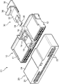
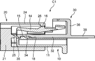
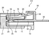
- FIG. 1 shows the wire harness which comprises the wiring system for vehicles which concerns on embodiment of this invention, and the some connector provided in this. It is a disassembled perspective view which shows each of the said some connector. It is sectional drawing which shows the state before the 1st connector housing and 2nd connector housing of the said connector fit. It is sectional drawing which shows the state in the middle of a said 1st connector housing and a said 2nd connector housing fitting. It is a cross section which shows the state which the said 1st connector housing and the said 2nd connector housing fitted normally. It is sectional drawing which shows the state which a connector identification member detaches
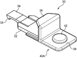
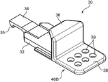
- FIG. 1 It is a perspective view which shows the 1st example of the connector identification member contained in the said connector, and includes an IC chip as an identification information holding part. It is a perspective view which shows the 2nd example of the connector identification member contained in the said connector, and the state in which the identification information holding
- FIG. 1 shows the vehicle wiring system according to the embodiment.
- This wiring system includes a wire harness WH and a plurality of connectors (in this embodiment, nine connectors C1, C2, C3, C4, C5, C6, C7, C8, and C9).
- the wire harness WH is composed of a plurality of electric wires bundled together, and has a main line 2 and a plurality of branch lines 4, 5, 6, and 7 branched from the main line 2.
- the plurality of connectors C1 to C9 are provided at the terminals of the trunk line 2 and the branch lines 4 to 7, respectively. That is, the plurality of connectors C1 to C9 are distributed and arranged at different locations in the wire harness WH.
- the connectors C1 to C9 according to this embodiment have the same structure. 2 to 6 representatively show the structure of the connector C1 among them.
- the connector C1 includes a first connector housing 10, a second connector housing 20 that can be fitted into the first connector housing 10, and a connector identification member 30.
- the first connector housing 10 is connected to the wire harness WH. Specifically, the first connector housing 10 collectively holds connector terminals respectively attached to ends of a plurality of electric wires included in the wire harness WH. More specifically, the first connector housing 10 has a substantially rectangular parallelepiped housing body 11 in which a plurality of terminal accommodating chambers 12 are formed, and the terminal accommodating chambers 12 accommodate the plurality of first connector terminals. ,Hold.
- the second connector housing 20 is provided on a connection object to be connected to the wire harness WH.
- the connection object is, for example, a wire harness or electric wires other than the wire harness WH, or an in-vehicle electronic device.
- the second connector housing 20 holds a plurality of second connector terminals in an arrangement corresponding to the first connector terminals.
- the second connector housing 20 has a substantially rectangular parallelepiped housing body 21 in which a plurality of terminal accommodating chambers 22 are formed, and each terminal accommodating chamber 22 accommodates and holds the second connector terminal. .
- the second connector housing 20 has a hood 24.
- the hood 24 has a rectangular tube shape extending from the housing body 21 in a specific direction (right direction in FIGS. 3 to 6).
- the hood 24 has a shape that opens in the specific direction and receives the fitting of the first connector housing 10 inside the hood 24.
- FIGS. 5 and 6 the plurality of first connector terminals and the first connector terminals held by the first connector housing 10 in a state where the first connector housing 10 is completely fitted in the hood 24.
- the plurality of second connector terminals held by the two-connector housing 20 are fitted together to form an electrical connection.
- the first and second connector housings 10 and 20 are provided with fitting lock portions.
- the fitting lock portion locks the fitting by engaging each other in a state where the first and second connector housings 10 and 20 are normally fitted.
- a downward locking projection 26 is formed at the end of the top wall of the hood 24, while the fitting lock piece 14 is located above the housing body 11 of the first connector housing 10. Is formed, and an upwardly-engaged projection 16 is formed on the upper surface of the fitting lock piece 14.
- the fitting lock piece 14 comes into contact with the locking projection 26 as the fitting of the first and second connector housings 10 and 20 progresses, and the locking projection 26 gets over the locked projection 16. In order to allow this, it can be elastically displaced downward as shown in FIG. Further, as shown in FIGS.
- the fitting lock piece 14 is elastically restored in a state where the fitting of the first and second connector housings 10 and 20 is normally completed, and the fitting lock piece 14 is restored.
- the locked protrusion 16 is locked to the locking protrusion 26, that is, a state where the fitting between the first and second connector housings 10, 20 is locked is formed.
- the first connector housing 10 has an identification member holding portion 18 that holds the connector identification member 30.
- the identification member holding portion 18 is formed between the upper surface of the housing main body 11 and the fitting lock piece 14, and holds the connector identification member 30 in a slidable manner.
- the connector identification member 30 holds identification information for identifying the connector to which the connector identification member 30 belongs (the connector C1 in FIGS. 2 to 6) from other connectors, while maintaining the identification information for the first connector housing 10. It is held so that it can be detached in the separation direction (in this embodiment, the direction parallel to the fitting direction).
- the connector identification member 30 according to this embodiment includes a main body portion 32, a locked piece 34, a lock piece cover portion 36, and an identification information holding portion.
- the main body 32 has a shape that can be held by the first connector housing 10, specifically, a flat plate that can be slidably inserted into the identification member holding portion 18.
- the locked piece 34 is a portion locked to the first connector housing 10, and is a direction parallel to the front direction, that is, the disengagement direction from the main body 32 and toward the second connector housing 20. And has a front end portion that can be deflected upward.
- a locked portion 35 that is a restrained portion is formed at the front end portion.
- the locked portion 35 is configured by a protrusion that protrudes downward.
- the identification member holding portion 18 of the first connector housing 10 includes a locking portion 15.
- the locking portion 15 is a restraining portion that locks or restrains the locked portion 35.
- the locking portion 15 according to this embodiment is a front end portion of the identification member holding portion 18, that is, an end portion closer to the second connector housing 20, and an end on the far side in the insertion direction of the connector identification member 30. It is comprised by the protrusion formed in the part, and protrudes upwards from the upper surface of the said housing main body 11. As shown in FIG.
- the locking portion 15 By engaging with the locked portion 35, the locking portion 15 cooperates with the fitting lock piece 14 that bends and displaces downward during fitting as described above, so that the connector identification member 30 is It is prevented that the connector identification member 30 is separated from the identification member holding portion 18 in the separation direction (the direction in which the connector identification member 30 is separated from the second connector housing 20 as indicated by an arrow in FIG. 6).
- the second connector housing 20 has an unlocking portion 25 which is a restraint releasing portion.
- the locking release portion 25 releases the locking of the locked portion 15 by the locking portion 35, that is, the restraint only when the first and second connector housings 10 and 20 are normally fitted.
- the unlocking portion 25 is constituted by a protrusion protruding from the housing body 21 into the hood 24, and the connector identification when the first connector housing 10 is inserted to the back of the hood 24. By contacting the locked portion 35 of the member 30 and forcibly bending it upward, the locked portion 35 is unlocked by the locking portion 15.
- the lock piece cover portion 36 has a shape that covers the fitting lock piece 14 in a state where the connector identification member 30 is held by the identification member holding portion 18 of the first connector housing 10. In this way, the lock piece cover portion 36 is fitted and locked when the fitting lock piece 14 of the first connector housing 10 is operated while the connector identification member 30 is held by the first connector housing 10. Is prevented from being released.
- the identification information holding unit holds the identification information, that is, information for identifying the connector (connector C1 in FIGS. 2 to 6) to which the connector identification member 30 belongs from other connectors (connectors C2 to C9). To do.
- the identification information holding unit according to this embodiment includes an operated piece 38 that extends from the main body 32 to the side opposite to the locked piece 34, that is, the front side in the detachment direction.
- the operated piece 38 functions as a part to be gripped for pulling out the connector identification member 30 from the first connector housing 10 in the detaching direction, and also functions as a component of the identification information holding unit.
- FIG. 7 shows an identification information holding unit 40A according to the first example.
- the identification information holding unit 40A further includes an IC chip 42 provided on the surface of the operated piece 38.
- the IC chip 42 stores the identification information as electronic information.
- This identification information is, for example, an identification number assigned to each of the connectors C1 to C9.
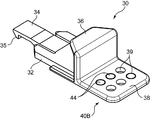
- FIG. 8 shows an identification information holding unit 40B according to the second example.
- the identification information holding unit 40B covers a plurality of (six in the example shown in FIG. 8) through-holes 39 formed in the operated piece 38 and any of the plurality of through-holes 39. And a hole filling material 44 that can be filled in the through hole.
- the identification information for identifying the connectors C1 to C9 is specified by the combination of the through holes filled with the hole filling material 44 of the through holes 39.
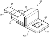
- FIG. 9 shows an identification information holding unit 40C according to the third example.
- the identification information holding unit 40 ⁇ / b> C includes an identification display 46 provided on the surface of the operated piece 38.
- the identification display 46 is formed, for example, by printing an identification number on the operated piece 38.
- the management of the fitting states of the connectors C1 to C9 can be easily and reliably performed in the following manner.
- the connector identification member is attached to the first connector housing 10 in advance. 30 is mounted. Specifically, the main body portion 32 of the connector identification member 30 is inserted into the identification member holding portion 18 of the first connector housing 10 in a direction opposite to the detachment direction. This insertion is performed until the locked portion 35 of the connector identification member 30 gets over the locking portion 15 of the identification member holding portion 18, that is, until the locked portion 35 is locked by the locking portion 15. Done.
- the fitting is performed by fitting the first connector housing 10 into the hood 24 of the second connector housing 20, as shown in FIGS.
- the engagement protrusion 16 of the engagement lock piece 14 of the first connector housing 10 comes into contact with the engagement protrusion 26 of the second connector housing 20, thereby the engagement lock.
- the piece 14 is deflected downward and displaced. Accordingly, at this stage, the locked portion 35 of the connector identification member 30 is locked to the locking portion 15, thereby preventing the connector identification member 30 from being detached from the identification member holding portion 18. Therefore, it is possible to prevent the connector identification member 30 from being detached from the first connector housing 10 when the first and second connector housings 10 and 20 are not sufficiently fitted.
- the engagement lock piece 14 is elastically restored, and the engagement protrusion 16 is engaged with the engagement protrusion 26 of the second connector housing 20.
- the fitting state between the second connector housings 10 and 20 is locked, and the unlocking portion 25 of the second connector housing 20 forcibly deflects and displaces the locked portion 35 of the connector identification member 30 upward.
- the locked portion 35 is unlocked by the locking portion 15. Accordingly, in this state, for example, the operator can grasp the operated piece 38 to separate the connector identification member 30 from the first connector housing 10 in the disengagement direction indicated by the arrow in FIG.
- the connector housing can be checked without checking the actual locations of the connectors C1 to C9. It is possible to specify a connector that is insufficiently fitted to each other.
- the first and second connectors C1 to C9 are all connected. It can be determined that the two connector housings 10 and 20 are completely fitted. Conversely, if the number of connector identification members 30 is less than the total number of connectors, the first and second connector housings 10 and 20 are not fitted to each other, or there is an insufficiently fitted connector. It will exist.
- the connector to which the recovered connector identification member 30 belongs can be specified by the identification information held by the identification information holding unit of each connector identification member 30. Therefore, conversely, a connector from which the connector identification member 30 has not been collected, that is, a connector in which the first and second connector housings 10 and 20 are not completely fitted together can be immediately identified.
- the identification information that is electronic information stored in the IC chip 42 can be read by, for example, an IC chip reader.
- the connector to which the connector identification member 30 including the identification information holding unit 40A belongs can be specified.
- the read electronic information can be directly input to a computer for centralized management. Therefore, it is possible to cope with a case where the total number of connectors is many. Further, the connector identification member 30 can be reused by erasing the electronic information stored in the IC chip 42 after use.
- the number and position of the through holes not blocked by the hole filling material 44 among the plurality of through holes 39 are measured by an optical sensor or the like. By reading, identification information associated with the number and position can be read. Also in the second example, the connector identification member 30 can be reused by removing the hole filling material 44.
- the identification information holding unit 40C can be acquired by visually recognizing the identification display 46 attached to the operated piece 38 or by reading with a dedicated reader. is there.
- the present invention is not limited to the embodiment described above.
- the present invention includes the following aspects, for example.
- the present invention also includes a wiring system including a plurality of wire harnesses and a plurality of connectors distributed in each wire harness. Also in this case, all the connectors provided in each wire harness can be collectively managed in the same manner as described above.
- the first and second connector housings included in each connector are not particularly limited as long as they can be fitted to each other.
- the present invention also includes a case where a plurality of second connector housings are fitted into a single first connector housing and a case where a plurality of first connector housings are fitted into a single second connector housing.
- a connector identification member is preferably provided for each of the fittings.
- the first connector housing may include a plurality of identification member holding portions.
- the connector identification member does not need to be given to all the connectors included in the vehicle. It is sufficient that the connector identification member is provided for a connector that requires collective management of fitting between connector housings.
- the vehicle wiring system according to the present invention may include only a part of all the connectors mounted on one vehicle.
- the shape and structure of the connector identification member according to the present invention can be freely set.
- the connector identification member may be, for example, spherical or columnar.
- the manner in which the identification member holding portion restrains the connector identification member and the manner in which the restraint releasing portion releases the restraint are not limited to those shown in FIGS.
- the identification member holding part may form a restraint chamber for confining the connector identification member, and the restraint release part may include a window for opening the restraint chamber.
- the identification information holding unit is not limited to the examples shown in FIGS.
- the second example shown in FIGS. 8 and 9 provides identification information according to the number and position of the through holes 39 actually opened in the operated piece 38, that is, according to the shape of the operated piece 38.
- the shape for providing the identification information is not limited to the one including the through hole.
- the identification information may be provided by the overall shape of the operated piece 38, the number of unevenness provided on the edge of the operated piece 38, the pitch, and the like.
- the through hole may not be closed afterwards by the hole filling material.
- a through hole may be provided only at a predetermined location for forming identification information.
- part in which a connector identification member comprises an identification information holding part is not limited.
- the operated piece 38 of the connector identification member 30 shown in FIGS. 7 to 10 may be omitted, and an identification information holding unit may be provided in other parts, for example, the main body 32 or the lock piece cover 36.
- a vehicle wiring system including a plurality of connectors, which can easily manage the fitting state of each connector collectively, and a method for managing the same are provided. Is done.
- a wiring system provided in a vehicle, which includes a plurality of connectors.
- Each connector includes a first connector housing, a second connector housing that forms an electrical connection state by fitting with the first connector housing, and a connector identification member that is held by the first connector housing.
- the first connector housing has an identification member holding portion for holding the connector identification member, and the identification member holding portion identifies the connector so as to prevent the connector identification member from being detached from the first connector housing. It has a restraint part which restrains a member.
- the second connector housing restrains the connector identifying member by the restraining portion so as to allow the connector identifying member to be detached only when the first connector housing and the second connector housing are normally fitted.
- the connector identification member includes an identification information holding unit that holds identification information for identifying a connector to which the connector identification member belongs from the other connectors.
- the provided management method includes preparing the vehicle wiring system and a restraining portion of the identification member holding portion of the first connector housing in each of the plurality of connectors included in the vehicle wiring system.
- the restraint by the restraining portion is released by restraining the connector identifying member, and the fitting of the first connector housing and the second connector housing in each connector, and from the identifying member holding portion of the first connector housing Collecting the released connector identification member, and the first connector housing and the first of the plurality of connectors based on the identification information held in the identification information holding portion of each of the collected connector identification members 2Features a connector that is not properly mated with the connector housing It is, including the capital.
- the connector housing between the connector housings be confirmed by the presence or absence of a connector identification member in each connector, but also a normal fitting can be performed.
- the connector in which the connector identification member is not collected that is, the connector in which normal connector housings are not fitted to each other
- the presence or absence of the connector and the specification of the connector when the connector exists can be easily performed. Therefore, it is possible to collectively manage the fitting states of all the connectors including the connector identification member among the connectors included in the vehicle wiring system.
- the vehicle wiring system preferably includes a wire harness routed in the vehicle, and the plurality of connectors are provided at different locations in the wire harness.
- the location of the plurality of connectors in the wire harness is specified, so the location of each connector can be easily specified based on the identification information held by the connector identification member collected from each connector. Is possible.
- the identification information holding unit of each connector identification member preferably includes, for example, an IC chip that stores the identification information as electronic information.
- the identification information (electronic information) stored in the IC chip can be easily read by an IC chip reader, for example.
- the read identification information can be easily managed by a computer.
- the identification information holding portion of each connector identification member has a shape given corresponding to the identification information to be held and is different from the shape of the identification information holding portion of the other connector identification member. May be. That is, the identification information may be converted into a shape possessed by the identification information holding unit.
Landscapes
- Engineering & Computer Science (AREA)
- Computer Hardware Design (AREA)
- Microelectronics & Electronic Packaging (AREA)
- Physics & Mathematics (AREA)
- General Physics & Mathematics (AREA)
- Theoretical Computer Science (AREA)
- Details Of Connecting Devices For Male And Female Coupling (AREA)
Priority Applications (3)
| Application Number | Priority Date | Filing Date | Title |
|---|---|---|---|
| US15/781,819 US10644452B2 (en) | 2015-12-24 | 2016-12-13 | Vehicular wiring system with first and second connector housings and identifying member that is removable only when first and second connector housings are connected properly |
| CN201680074955.9A CN108432063B (zh) | 2015-12-24 | 2016-12-13 | 车辆用布线系统 |
| DE112016006007.6T DE112016006007T5 (de) | 2015-12-24 | 2016-12-13 | Fahrzeugverdrahtungssystem |
Applications Claiming Priority (2)
| Application Number | Priority Date | Filing Date | Title |
|---|---|---|---|
| JP2015-250988 | 2015-12-24 | ||
| JP2015250988A JP6597287B2 (ja) | 2015-12-24 | 2015-12-24 | 車両のワイヤリングシステム |
Publications (1)
| Publication Number | Publication Date |
|---|---|
| WO2017110597A1 true WO2017110597A1 (ja) | 2017-06-29 |
Family
ID=59090241
Family Applications (1)
| Application Number | Title | Priority Date | Filing Date |
|---|---|---|---|
| PCT/JP2016/087120 Ceased WO2017110597A1 (ja) | 2015-12-24 | 2016-12-13 | 車両用ワイヤリングシステム |
Country Status (5)
| Country | Link |
|---|---|
| US (1) | US10644452B2 (enExample) |
| JP (1) | JP6597287B2 (enExample) |
| CN (1) | CN108432063B (enExample) |
| DE (1) | DE112016006007T5 (enExample) |
| WO (1) | WO2017110597A1 (enExample) |
Families Citing this family (5)
| Publication number | Priority date | Publication date | Assignee | Title |
|---|---|---|---|---|
| JP6996487B2 (ja) * | 2018-12-25 | 2022-01-17 | 株式会社オートネットワーク技術研究所 | コネクタ |
| JP7226110B2 (ja) | 2019-05-31 | 2023-02-21 | 株式会社オートネットワーク技術研究所 | 配線部材 |
| JP7414635B2 (ja) | 2020-05-07 | 2024-01-16 | 日本航空電子工業株式会社 | コネクタ組立体 |
| DE102020210760A1 (de) * | 2020-08-25 | 2022-03-03 | Te Connectivity Germany Gmbh | Stecker mit einem Lagesicherungselement mit einer Kontaktaufnahme |
| US20240375597A1 (en) * | 2023-05-10 | 2024-11-14 | Newrad Solutions, LLC | Wire harness for vehicle digital dashboard conversion |
Citations (4)
| Publication number | Priority date | Publication date | Assignee | Title |
|---|---|---|---|---|
| JPH03297078A (ja) * | 1990-04-16 | 1991-12-27 | Sumitomo Wiring Syst Ltd | コネクタ |
| JPH07192808A (ja) * | 1993-12-28 | 1995-07-28 | Yazaki Corp | コネクタのロック保障機構 |
| JP2006065534A (ja) * | 2004-08-26 | 2006-03-09 | Hitachi Ltd | 薄板管理用冶具 |
| WO2015111225A1 (ja) * | 2014-01-27 | 2015-07-30 | 三菱電機株式会社 | 部品管理システム、部品管理装置、部品管理方法及びプログラム |
Family Cites Families (23)
| Publication number | Priority date | Publication date | Assignee | Title |
|---|---|---|---|---|
| US44140A (en) * | 1864-09-06 | assigfok to himself | ||
| GB1249805A (en) * | 1969-05-08 | 1971-10-13 | Vauxhall Motors Ltd | Electrical connectors |
| US4486065A (en) * | 1981-04-27 | 1984-12-04 | Wittes James M | Strain-relief electrical cable connector |
| US5120255A (en) * | 1990-03-01 | 1992-06-09 | Yazaki Corporation | Complete locking confirming device for confirming the complete locking of an electric connector |
| US5217390A (en) * | 1990-04-16 | 1993-06-08 | Sumitomo Wiring Systems, Ltd. | Connector |
| GB2249438B (en) * | 1990-10-08 | 1995-01-18 | Sumitomo Wiring Systems | Connector |
| US5507666A (en) * | 1993-12-28 | 1996-04-16 | Yazaki Corporation | Lock securing mechanism for connectors |
| JP3013444U (ja) * | 1994-05-19 | 1995-07-18 | ▲高▼松建設株式会社 | Av機器類の接続用具 |
| JP3424780B2 (ja) * | 1995-06-30 | 2003-07-07 | 矢崎総業株式会社 | 嵌合検知具を備えたコネクタ |
| US6261116B1 (en) * | 1999-11-22 | 2001-07-17 | Yazaki North America, Inc. | Connector position assurance element with lock protection feature |
| JP2001185290A (ja) * | 1999-12-27 | 2001-07-06 | Sumitomo Wiring Syst Ltd | コネクタ |
| JP2002283934A (ja) * | 2001-01-22 | 2002-10-03 | Sumitomo Wiring Syst Ltd | 自動車に搭載される機器とワイヤハーネスの接続システム |
| US6970755B2 (en) * | 2001-06-13 | 2005-11-29 | Sumitomo Wiring Systems, Ltd. | Method, computer program and system for designing a wiring harness assembling table |
| JP3726737B2 (ja) * | 2001-11-07 | 2005-12-14 | 住友電装株式会社 | ワイヤーハーネス設計システム |
| DE102004007353A1 (de) | 2004-02-16 | 2005-09-01 | Volkswagen Ag | Prüfeinrichtung für eine Steckverbindung |
| JP4571854B2 (ja) * | 2004-12-22 | 2010-10-27 | 矢崎総業株式会社 | コネクタ |
| JP4876985B2 (ja) * | 2007-03-09 | 2012-02-15 | 住友電装株式会社 | コネクタ |
| DE102008035193A1 (de) * | 2008-07-28 | 2010-02-11 | Tyco Electronics Amp Gmbh | Kontrollierbare Steckverbindung und Verfahren zur Kontrolle des Steckzustandes einer Steckverbindung |
| CN201838782U (zh) * | 2010-06-25 | 2011-05-18 | 叶伟训 | 可标示识别标记的插座 |
| WO2014047636A1 (en) * | 2012-09-24 | 2014-03-27 | Iridex Corporation | Hybrid device identifier |
| US10326229B2 (en) * | 2013-03-15 | 2019-06-18 | Knxid, Llc | Termination identification device and system |
| US9748695B2 (en) * | 2014-04-30 | 2017-08-29 | Ford Global Technologies, Llc | High voltage connector assembly |
| US10044140B1 (en) * | 2015-12-28 | 2018-08-07 | Amazon Technologies, Inc. | Physical cable seating confirmation for network cables |
-
2015
- 2015-12-24 JP JP2015250988A patent/JP6597287B2/ja not_active Expired - Fee Related
-
2016
- 2016-12-13 DE DE112016006007.6T patent/DE112016006007T5/de not_active Withdrawn
- 2016-12-13 WO PCT/JP2016/087120 patent/WO2017110597A1/ja not_active Ceased
- 2016-12-13 US US15/781,819 patent/US10644452B2/en active Active
- 2016-12-13 CN CN201680074955.9A patent/CN108432063B/zh not_active Expired - Fee Related
Patent Citations (4)
| Publication number | Priority date | Publication date | Assignee | Title |
|---|---|---|---|---|
| JPH03297078A (ja) * | 1990-04-16 | 1991-12-27 | Sumitomo Wiring Syst Ltd | コネクタ |
| JPH07192808A (ja) * | 1993-12-28 | 1995-07-28 | Yazaki Corp | コネクタのロック保障機構 |
| JP2006065534A (ja) * | 2004-08-26 | 2006-03-09 | Hitachi Ltd | 薄板管理用冶具 |
| WO2015111225A1 (ja) * | 2014-01-27 | 2015-07-30 | 三菱電機株式会社 | 部品管理システム、部品管理装置、部品管理方法及びプログラム |
Also Published As
| Publication number | Publication date |
|---|---|
| CN108432063A (zh) | 2018-08-21 |
| DE112016006007T5 (de) | 2018-09-06 |
| CN108432063B (zh) | 2020-03-13 |
| US20180358750A1 (en) | 2018-12-13 |
| JP6597287B2 (ja) | 2019-10-30 |
| US10644452B2 (en) | 2020-05-05 |
| JP2017117610A (ja) | 2017-06-29 |
Similar Documents
| Publication | Publication Date | Title |
|---|---|---|
| JP6597287B2 (ja) | 車両のワイヤリングシステム | |
| US10978827B2 (en) | On-board diagnostic port connector locking mechanism | |
| EP3381091B1 (en) | Electrical connector with recordable position assurance | |
| US7988493B2 (en) | Electrical component holder | |
| CN112652916A (zh) | 具有连接件位置保证标志的连接件组件 | |
| US9502814B2 (en) | Connector cover and connector connecting apparatus | |
| CN102171893A (zh) | 连接单元、电子装置、连接单元拔脱方法 | |
| CN101522474A (zh) | 电路单元收容箱 | |
| JP4472741B2 (ja) | ヒューズプラーおよび電気接続箱 | |
| JP3413979B2 (ja) | 後入れ端子の仮保持治具並びにそれに用いる挿入治具 | |
| JP5932758B2 (ja) | ケーブル誤接続防止治具及びケーブル誤接続防止方法 | |
| JP5488364B2 (ja) | 電気接続箱組立ユニット | |
| JP5814817B2 (ja) | 光コネクタアダプタを識別するための補助具及び補助具の取り付け方法 | |
| JP4958530B2 (ja) | コネクタカバーおよび遊技機 | |
| US9726832B2 (en) | Secure SC optical fiber connector and removal tools | |
| JP4999630B2 (ja) | 車載用の故障診断装置 | |
| DE102007023401B4 (de) | Mess- und Schnittstellenmodul, Anordnung derartiger Module und Verfahren zu deren Verbindung | |
| CN119744356A (zh) | 断线检查装置和断线检查方法 | |
| JP6998793B2 (ja) | 表示具、及び表示具生成具 | |
| JP4347266B2 (ja) | 電気機器の分解構造 | |
| JP4298619B2 (ja) | プリント基板の筐体構造 | |
| DE10121253B4 (de) | Diebstahl - und Mitlesesicherung | |
| JP2002214480A (ja) | 光コネクタ誤脱防止プレート | |
| EP0996198A1 (en) | An electrical connection box, a positioning method and a testing device for the same | |
| US20220113484A1 (en) | Connector plug, connector insertion method, and a connector removal method |
Legal Events
| Date | Code | Title | Description |
|---|---|---|---|
| 121 | Ep: the epo has been informed by wipo that ep was designated in this application |
Ref document number: 16878488 Country of ref document: EP Kind code of ref document: A1 |
|
| WWE | Wipo information: entry into national phase |
Ref document number: 112016006007 Country of ref document: DE |
|
| 122 | Ep: pct application non-entry in european phase |
Ref document number: 16878488 Country of ref document: EP Kind code of ref document: A1 |