WO2017104745A1 - 流体吐出装置および流体吐出方法 - Google Patents
流体吐出装置および流体吐出方法 Download PDFInfo
- Publication number
- WO2017104745A1 WO2017104745A1 PCT/JP2016/087369 JP2016087369W WO2017104745A1 WO 2017104745 A1 WO2017104745 A1 WO 2017104745A1 JP 2016087369 W JP2016087369 W JP 2016087369W WO 2017104745 A1 WO2017104745 A1 WO 2017104745A1
- Authority
- WO
- WIPO (PCT)
- Prior art keywords
- fluid
- ejection
- head
- discharge
- workpiece
- Prior art date
Links
Images


Classifications
-
- H—ELECTRICITY
- H05—ELECTRIC TECHNIQUES NOT OTHERWISE PROVIDED FOR
- H05K—PRINTED CIRCUITS; CASINGS OR CONSTRUCTIONAL DETAILS OF ELECTRIC APPARATUS; MANUFACTURE OF ASSEMBLAGES OF ELECTRICAL COMPONENTS
- H05K3/00—Apparatus or processes for manufacturing printed circuits
- H05K3/30—Assembling printed circuits with electric components, e.g. with resistor
- H05K3/32—Assembling printed circuits with electric components, e.g. with resistor electrically connecting electric components or wires to printed circuits
- H05K3/34—Assembling printed circuits with electric components, e.g. with resistor electrically connecting electric components or wires to printed circuits by soldering
- H05K3/3457—Solder materials or compositions; Methods of application thereof
- H05K3/3468—Applying molten solder
-
- B—PERFORMING OPERATIONS; TRANSPORTING
- B05—SPRAYING OR ATOMISING IN GENERAL; APPLYING FLUENT MATERIALS TO SURFACES, IN GENERAL
- B05C—APPARATUS FOR APPLYING FLUENT MATERIALS TO SURFACES, IN GENERAL
- B05C11/00—Component parts, details or accessories not specifically provided for in groups B05C1/00 - B05C9/00
- B05C11/10—Storage, supply or control of liquid or other fluent material; Recovery of excess liquid or other fluent material
-
- B—PERFORMING OPERATIONS; TRANSPORTING
- B05—SPRAYING OR ATOMISING IN GENERAL; APPLYING FLUENT MATERIALS TO SURFACES, IN GENERAL
- B05C—APPARATUS FOR APPLYING FLUENT MATERIALS TO SURFACES, IN GENERAL
- B05C13/00—Means for manipulating or holding work, e.g. for separate articles
- B05C13/02—Means for manipulating or holding work, e.g. for separate articles for particular articles
-
- B—PERFORMING OPERATIONS; TRANSPORTING
- B05—SPRAYING OR ATOMISING IN GENERAL; APPLYING FLUENT MATERIALS TO SURFACES, IN GENERAL
- B05C—APPARATUS FOR APPLYING FLUENT MATERIALS TO SURFACES, IN GENERAL
- B05C21/00—Accessories or implements for use in connection with applying liquids or other fluent materials to surfaces, not provided for in groups B05C1/00 - B05C19/00
-
- B—PERFORMING OPERATIONS; TRANSPORTING
- B05—SPRAYING OR ATOMISING IN GENERAL; APPLYING FLUENT MATERIALS TO SURFACES, IN GENERAL
- B05C—APPARATUS FOR APPLYING FLUENT MATERIALS TO SURFACES, IN GENERAL
- B05C5/00—Apparatus in which liquid or other fluent material is projected, poured or allowed to flow on to the surface of the work
- B05C5/001—Apparatus in which liquid or other fluent material is projected, poured or allowed to flow on to the surface of the work incorporating means for heating or cooling the liquid or other fluent material
-
- B—PERFORMING OPERATIONS; TRANSPORTING
- B05—SPRAYING OR ATOMISING IN GENERAL; APPLYING FLUENT MATERIALS TO SURFACES, IN GENERAL
- B05C—APPARATUS FOR APPLYING FLUENT MATERIALS TO SURFACES, IN GENERAL
- B05C5/00—Apparatus in which liquid or other fluent material is projected, poured or allowed to flow on to the surface of the work
- B05C5/02—Apparatus in which liquid or other fluent material is projected, poured or allowed to flow on to the surface of the work the liquid or other fluent material being discharged through an outlet orifice by pressure, e.g. from an outlet device in contact or almost in contact, with the work
-
- B—PERFORMING OPERATIONS; TRANSPORTING
- B05—SPRAYING OR ATOMISING IN GENERAL; APPLYING FLUENT MATERIALS TO SURFACES, IN GENERAL
- B05C—APPARATUS FOR APPLYING FLUENT MATERIALS TO SURFACES, IN GENERAL
- B05C9/00—Apparatus or plant for applying liquid or other fluent material to surfaces by means not covered by any preceding group, or in which the means of applying the liquid or other fluent material is not important
- B05C9/08—Apparatus or plant for applying liquid or other fluent material to surfaces by means not covered by any preceding group, or in which the means of applying the liquid or other fluent material is not important for applying liquid or other fluent material and performing an auxiliary operation
- B05C9/12—Apparatus or plant for applying liquid or other fluent material to surfaces by means not covered by any preceding group, or in which the means of applying the liquid or other fluent material is not important for applying liquid or other fluent material and performing an auxiliary operation the auxiliary operation being performed after the application
-
- B—PERFORMING OPERATIONS; TRANSPORTING
- B05—SPRAYING OR ATOMISING IN GENERAL; APPLYING FLUENT MATERIALS TO SURFACES, IN GENERAL
- B05C—APPARATUS FOR APPLYING FLUENT MATERIALS TO SURFACES, IN GENERAL
- B05C9/00—Apparatus or plant for applying liquid or other fluent material to surfaces by means not covered by any preceding group, or in which the means of applying the liquid or other fluent material is not important
- B05C9/08—Apparatus or plant for applying liquid or other fluent material to surfaces by means not covered by any preceding group, or in which the means of applying the liquid or other fluent material is not important for applying liquid or other fluent material and performing an auxiliary operation
- B05C9/14—Apparatus or plant for applying liquid or other fluent material to surfaces by means not covered by any preceding group, or in which the means of applying the liquid or other fluent material is not important for applying liquid or other fluent material and performing an auxiliary operation the auxiliary operation involving heating or cooling
-
- B—PERFORMING OPERATIONS; TRANSPORTING
- B05—SPRAYING OR ATOMISING IN GENERAL; APPLYING FLUENT MATERIALS TO SURFACES, IN GENERAL
- B05D—PROCESSES FOR APPLYING FLUENT MATERIALS TO SURFACES, IN GENERAL
- B05D1/00—Processes for applying liquids or other fluent materials
- B05D1/26—Processes for applying liquids or other fluent materials performed by applying the liquid or other fluent material from an outlet device in contact with, or almost in contact with, the surface
-
- B—PERFORMING OPERATIONS; TRANSPORTING
- B05—SPRAYING OR ATOMISING IN GENERAL; APPLYING FLUENT MATERIALS TO SURFACES, IN GENERAL
- B05D—PROCESSES FOR APPLYING FLUENT MATERIALS TO SURFACES, IN GENERAL
- B05D3/00—Pretreatment of surfaces to which liquids or other fluent materials are to be applied; After-treatment of applied coatings, e.g. intermediate treating of an applied coating preparatory to subsequent applications of liquids or other fluent materials
- B05D3/12—Pretreatment of surfaces to which liquids or other fluent materials are to be applied; After-treatment of applied coatings, e.g. intermediate treating of an applied coating preparatory to subsequent applications of liquids or other fluent materials by mechanical means
-
- B—PERFORMING OPERATIONS; TRANSPORTING
- B05—SPRAYING OR ATOMISING IN GENERAL; APPLYING FLUENT MATERIALS TO SURFACES, IN GENERAL
- B05D—PROCESSES FOR APPLYING FLUENT MATERIALS TO SURFACES, IN GENERAL
- B05D7/00—Processes, other than flocking, specially adapted for applying liquids or other fluent materials to particular surfaces or for applying particular liquids or other fluent materials
-
- B—PERFORMING OPERATIONS; TRANSPORTING
- B23—MACHINE TOOLS; METAL-WORKING NOT OTHERWISE PROVIDED FOR
- B23K—SOLDERING OR UNSOLDERING; WELDING; CLADDING OR PLATING BY SOLDERING OR WELDING; CUTTING BY APPLYING HEAT LOCALLY, e.g. FLAME CUTTING; WORKING BY LASER BEAM
- B23K1/00—Soldering, e.g. brazing, or unsoldering
- B23K1/0008—Soldering, e.g. brazing, or unsoldering specially adapted for particular articles or work
- B23K1/0016—Brazing of electronic components
-
- B—PERFORMING OPERATIONS; TRANSPORTING
- B23—MACHINE TOOLS; METAL-WORKING NOT OTHERWISE PROVIDED FOR
- B23K—SOLDERING OR UNSOLDERING; WELDING; CLADDING OR PLATING BY SOLDERING OR WELDING; CUTTING BY APPLYING HEAT LOCALLY, e.g. FLAME CUTTING; WORKING BY LASER BEAM
- B23K1/00—Soldering, e.g. brazing, or unsoldering
- B23K1/20—Preliminary treatment of work or areas to be soldered, e.g. in respect of a galvanic coating
-
- B—PERFORMING OPERATIONS; TRANSPORTING
- B23—MACHINE TOOLS; METAL-WORKING NOT OTHERWISE PROVIDED FOR
- B23K—SOLDERING OR UNSOLDERING; WELDING; CLADDING OR PLATING BY SOLDERING OR WELDING; CUTTING BY APPLYING HEAT LOCALLY, e.g. FLAME CUTTING; WORKING BY LASER BEAM
- B23K3/00—Tools, devices, or special appurtenances for soldering, e.g. brazing, or unsoldering, not specially adapted for particular methods
- B23K3/06—Solder feeding devices; Solder melting pans
- B23K3/0607—Solder feeding devices
- B23K3/0623—Solder feeding devices for shaped solder piece feeding, e.g. preforms, bumps, balls, pellets, droplets
-
- B—PERFORMING OPERATIONS; TRANSPORTING
- B23—MACHINE TOOLS; METAL-WORKING NOT OTHERWISE PROVIDED FOR
- B23K—SOLDERING OR UNSOLDERING; WELDING; CLADDING OR PLATING BY SOLDERING OR WELDING; CUTTING BY APPLYING HEAT LOCALLY, e.g. FLAME CUTTING; WORKING BY LASER BEAM
- B23K3/00—Tools, devices, or special appurtenances for soldering, e.g. brazing, or unsoldering, not specially adapted for particular methods
- B23K3/06—Solder feeding devices; Solder melting pans
- B23K3/0607—Solder feeding devices
- B23K3/0638—Solder feeding devices for viscous material feeding, e.g. solder paste feeding
-
- H—ELECTRICITY
- H01—ELECTRIC ELEMENTS
- H01L—SEMICONDUCTOR DEVICES NOT COVERED BY CLASS H10
- H01L24/00—Arrangements for connecting or disconnecting semiconductor or solid-state bodies; Methods or apparatus related thereto
- H01L24/01—Means for bonding being attached to, or being formed on, the surface to be connected, e.g. chip-to-package, die-attach, "first-level" interconnects; Manufacturing methods related thereto
- H01L24/10—Bump connectors ; Manufacturing methods related thereto
- H01L24/11—Manufacturing methods
-
- H—ELECTRICITY
- H01—ELECTRIC ELEMENTS
- H01L—SEMICONDUCTOR DEVICES NOT COVERED BY CLASS H10
- H01L24/00—Arrangements for connecting or disconnecting semiconductor or solid-state bodies; Methods or apparatus related thereto
- H01L24/74—Apparatus for manufacturing arrangements for connecting or disconnecting semiconductor or solid-state bodies
- H01L24/741—Apparatus for manufacturing means for bonding, e.g. connectors
- H01L24/742—Apparatus for manufacturing bump connectors
-
- H—ELECTRICITY
- H05—ELECTRIC TECHNIQUES NOT OTHERWISE PROVIDED FOR
- H05K—PRINTED CIRCUITS; CASINGS OR CONSTRUCTIONAL DETAILS OF ELECTRIC APPARATUS; MANUFACTURE OF ASSEMBLAGES OF ELECTRICAL COMPONENTS
- H05K3/00—Apparatus or processes for manufacturing printed circuits
- H05K3/10—Apparatus or processes for manufacturing printed circuits in which conductive material is applied to the insulating support in such a manner as to form the desired conductive pattern
- H05K3/14—Apparatus or processes for manufacturing printed circuits in which conductive material is applied to the insulating support in such a manner as to form the desired conductive pattern using spraying techniques to apply the conductive material, e.g. vapour evaporation
- H05K3/143—Masks therefor
-
- H—ELECTRICITY
- H05—ELECTRIC TECHNIQUES NOT OTHERWISE PROVIDED FOR
- H05K—PRINTED CIRCUITS; CASINGS OR CONSTRUCTIONAL DETAILS OF ELECTRIC APPARATUS; MANUFACTURE OF ASSEMBLAGES OF ELECTRICAL COMPONENTS
- H05K3/00—Apparatus or processes for manufacturing printed circuits
- H05K3/22—Secondary treatment of printed circuits
- H05K3/28—Applying non-metallic protective coatings
-
- H—ELECTRICITY
- H05—ELECTRIC TECHNIQUES NOT OTHERWISE PROVIDED FOR
- H05K—PRINTED CIRCUITS; CASINGS OR CONSTRUCTIONAL DETAILS OF ELECTRIC APPARATUS; MANUFACTURE OF ASSEMBLAGES OF ELECTRICAL COMPONENTS
- H05K3/00—Apparatus or processes for manufacturing printed circuits
- H05K3/30—Assembling printed circuits with electric components, e.g. with resistor
- H05K3/32—Assembling printed circuits with electric components, e.g. with resistor electrically connecting electric components or wires to printed circuits
- H05K3/34—Assembling printed circuits with electric components, e.g. with resistor electrically connecting electric components or wires to printed circuits by soldering
-
- B—PERFORMING OPERATIONS; TRANSPORTING
- B23—MACHINE TOOLS; METAL-WORKING NOT OTHERWISE PROVIDED FOR
- B23K—SOLDERING OR UNSOLDERING; WELDING; CLADDING OR PLATING BY SOLDERING OR WELDING; CUTTING BY APPLYING HEAT LOCALLY, e.g. FLAME CUTTING; WORKING BY LASER BEAM
- B23K1/00—Soldering, e.g. brazing, or unsoldering
- B23K1/018—Unsoldering; Removal of melted solder or other residues
-
- B—PERFORMING OPERATIONS; TRANSPORTING
- B23—MACHINE TOOLS; METAL-WORKING NOT OTHERWISE PROVIDED FOR
- B23K—SOLDERING OR UNSOLDERING; WELDING; CLADDING OR PLATING BY SOLDERING OR WELDING; CUTTING BY APPLYING HEAT LOCALLY, e.g. FLAME CUTTING; WORKING BY LASER BEAM
- B23K1/00—Soldering, e.g. brazing, or unsoldering
- B23K1/20—Preliminary treatment of work or areas to be soldered, e.g. in respect of a galvanic coating
- B23K1/206—Cleaning
-
- B—PERFORMING OPERATIONS; TRANSPORTING
- B23—MACHINE TOOLS; METAL-WORKING NOT OTHERWISE PROVIDED FOR
- B23K—SOLDERING OR UNSOLDERING; WELDING; CLADDING OR PLATING BY SOLDERING OR WELDING; CUTTING BY APPLYING HEAT LOCALLY, e.g. FLAME CUTTING; WORKING BY LASER BEAM
- B23K2101/00—Articles made by soldering, welding or cutting
- B23K2101/36—Electric or electronic devices
- B23K2101/40—Semiconductor devices
-
- B—PERFORMING OPERATIONS; TRANSPORTING
- B23—MACHINE TOOLS; METAL-WORKING NOT OTHERWISE PROVIDED FOR
- B23K—SOLDERING OR UNSOLDERING; WELDING; CLADDING OR PLATING BY SOLDERING OR WELDING; CUTTING BY APPLYING HEAT LOCALLY, e.g. FLAME CUTTING; WORKING BY LASER BEAM
- B23K2101/00—Articles made by soldering, welding or cutting
- B23K2101/36—Electric or electronic devices
- B23K2101/42—Printed circuits
-
- H—ELECTRICITY
- H01—ELECTRIC ELEMENTS
- H01L—SEMICONDUCTOR DEVICES NOT COVERED BY CLASS H10
- H01L2224/00—Indexing scheme for arrangements for connecting or disconnecting semiconductor or solid-state bodies and methods related thereto as covered by H01L24/00
- H01L2224/01—Means for bonding being attached to, or being formed on, the surface to be connected, e.g. chip-to-package, die-attach, "first-level" interconnects; Manufacturing methods related thereto
- H01L2224/10—Bump connectors; Manufacturing methods related thereto
- H01L2224/11—Manufacturing methods
- H01L2224/113—Manufacturing methods by local deposition of the material of the bump connector
- H01L2224/1131—Manufacturing methods by local deposition of the material of the bump connector in liquid form
- H01L2224/11312—Continuous flow, e.g. using a microsyringe, a pump, a nozzle or extrusion
-
- H—ELECTRICITY
- H01—ELECTRIC ELEMENTS
- H01L—SEMICONDUCTOR DEVICES NOT COVERED BY CLASS H10
- H01L2224/00—Indexing scheme for arrangements for connecting or disconnecting semiconductor or solid-state bodies and methods related thereto as covered by H01L24/00
- H01L2224/01—Means for bonding being attached to, or being formed on, the surface to be connected, e.g. chip-to-package, die-attach, "first-level" interconnects; Manufacturing methods related thereto
- H01L2224/10—Bump connectors; Manufacturing methods related thereto
- H01L2224/12—Structure, shape, material or disposition of the bump connectors prior to the connecting process
- H01L2224/13—Structure, shape, material or disposition of the bump connectors prior to the connecting process of an individual bump connector
- H01L2224/13001—Core members of the bump connector
- H01L2224/13099—Material
- H01L2224/131—Material with a principal constituent of the material being a metal or a metalloid, e.g. boron [B], silicon [Si], germanium [Ge], arsenic [As], antimony [Sb], tellurium [Te] and polonium [Po], and alloys thereof
-
- H—ELECTRICITY
- H01—ELECTRIC ELEMENTS
- H01L—SEMICONDUCTOR DEVICES NOT COVERED BY CLASS H10
- H01L24/00—Arrangements for connecting or disconnecting semiconductor or solid-state bodies; Methods or apparatus related thereto
- H01L24/01—Means for bonding being attached to, or being formed on, the surface to be connected, e.g. chip-to-package, die-attach, "first-level" interconnects; Manufacturing methods related thereto
- H01L24/10—Bump connectors ; Manufacturing methods related thereto
- H01L24/12—Structure, shape, material or disposition of the bump connectors prior to the connecting process
- H01L24/13—Structure, shape, material or disposition of the bump connectors prior to the connecting process of an individual bump connector
Definitions
- the present invention relates to an apparatus for discharging a fluid such as molten solder or adhesive onto a workpiece of an electronic component such as a substrate and a semiconductor.
- Solder and adhesive are used for mounting electronic parts such as semiconductors on printed circuit boards of electronic devices and for assembling electronic parts such as semiconductors.
- electronic parts made of ceramics cannot be soldered as they are. Therefore, a pad made of a plating film is provided on the surface of the workpiece of the electronic component, and a solder bump (kump) is formed on the pad. Thereafter, soldering is performed via bumps.
- kump solder bump
- solder paste is often used as a solder bump forming method. After applying the solder paste on the plating film of the workpiece with a printing machine or a dispenser, the solder paste is melted by reflow heating to form bumps. This method is inexpensive. However, printing has a limit that can be printed, and bumps corresponding to fine circuit patterns cannot be formed.
- solder balls There is also a bump formation method using solder balls.
- a fine solder ball is mounted on the work of the electronic component, and bumps are formed by reflow heating. This method can form bumps corresponding to fine circuit patterns.
- the cost of the solder ball itself is high, the overall cost is high.
- a so-called molten solder method in which molten solder is discharged to form a solder bump has attracted attention.
- a solder attaching apparatus described in Patent Document 1 below is known. This solder application apparatus efficiently supplies molten solder to a plurality of locations by scanning the nozzle opening of a container containing molten solder in the horizontal direction.
- a bump forming apparatus having a mechanism for lifting the nozzle head from the mask after the nozzle head is cooled after the work is completed.
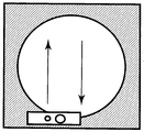
- the size of the ejection head is generally the same as that of a workpiece such as a silicon wafer or a printed board as shown in FIG.
- the ejection head moves in a certain direction. Accordingly, it is possible to prevent the mask from being bent by moving the squeegee with a small number of scans.
- the present invention has been made to solve at least a part of the above-described problems, and can be realized as, for example, the following modes.
- a fluid ejection method for applying a fluid into a mask on a workpiece of an electronic component.
- a head having a width shorter than the length of the work which is composed of a tank capable of storing a fluid and a discharge head, has a suction port for sucking the contents of the mask on the work.
- a discharge nozzle for discharging fluid is formed in the vicinity thereof, and the suction port uses a fluid discharge device installed in front of the moving direction of the discharge head to reciprocate the discharge head with respect to the workpiece.
- the first embodiment it is possible to reduce the deformation of the mask by reciprocating the discharge head with respect to the workpiece as shown in FIG. Specifically, the mask deformed once when the deformation of the mask that has occurred when the ejection head moves in the first direction is moved again in the second direction that is opposite to the first direction. Therefore, the deformation of the mask can be reduced.
- a fluid ejection device for applying a fluid into a mask on a workpiece of an electronic component.
- This fluid discharge device is a head portion having a width shorter than the length of a work, which is composed of a tank capable of storing a fluid and a discharge head.
- the discharge head has a work piece in the vicinity of a discharge nozzle for discharging a fluid.
- a suction port having a slit-like opening for sucking the contents of the upper mask is arranged on both sides of the discharge nozzle.
- the deformation of the mask is not biased in one direction and the deformation of the mask is reduced, so that the discharge amount does not vary, and the fluid with a stable discharge amount is obtained. Can be discharged. Therefore, the enormous correction that has occurred by applying fluid to a fine mask in a conventional workpiece is eliminated, and the productivity is dramatically improved.
- a fluid ejection device for applying a fluid into a mask on a workpiece of an electronic component.
- the fluid ejection device includes a plurality of head portions smaller than a work, each of which includes a tank capable of storing a fluid and a discharge head, and the head portions move in a horizontal direction on the work in synchronization with each other.
- the same amount of fluid can be discharged stably by degassing and depressurizing the air in the mask on the work before discharging the fluid.
- a fluid ejection method for applying a fluid into a mask on a workpiece of an electronic component.
- This fluid discharge method has a plurality of head portions that are smaller than the workpiece and can be varied in angle, and are composed of a tank capable of containing fluid and a discharge head, and the head portions are synchronized with each other in the horizontal direction on the workpiece.
- the discharge head is formed with a suction port for sucking the contents of the mask on the workpiece and a discharge nozzle for discharging a fluid in the vicinity of the suction port. It is installed in the front of the traveling direction, and the air in the mask on the work before discharging the fluid is deaerated and decompressed to discharge the same amount of fluid in a stable manner.
- the plurality of divided head portions may be any size as long as the pressure from the vertical direction applied to the head portion is evenly applied. Specifically, it is preferably 1/2 to 1/4 of the left and right length of the workpiece. Further, the number of the plurality of head portions used in the present application can be determined in accordance with the size of the workpiece, but 2 to 4 are suitable for easy handling.
- the work is discharged onto a circular object such as a silicon wafer, it is optimal to use three head portions. As shown in FIG. 6, in discharging to a circular workpiece, the head portion is not only moved horizontally in the front-rear direction, but also by changing the angle of the head portions arranged on the left and right along the circumference, compared to a square shape. Even for circular workpieces that are difficult to discharge, a uniform discharge amount can be obtained.
- the head portion is shorter than the work, the pressure applied from the discharge head to the work is not necessarily evenly distributed, and the discharge amount does not vary. Can be added to the workpiece.
- the head parts move in the horizontal direction on the workpiece in synchronization with each other, there is no discharge leakage and it is possible to discharge a stable discharge amount of fluid. Therefore, the enormous correction that has occurred by applying fluid to a fine mask in a conventional workpiece is eliminated, and the productivity is dramatically improved.
- a fluid ejection device for applying a fluid onto a workpiece of an electronic component.
- This fluid ejection device is a first stage for supporting a workpiece, and a first ejection head configured to eject fluid while linearly moving in the horizontal direction above the workpiece,
- the first discharge head configured to move from the initial position outside the first stage to the final position outside the first stage via the top of the first stage, while changing the arrangement angle From the initial position to the outer edge of the first stage on the second discharge head configured to discharge the fluid while moving in the horizontal direction above the first stage, and on the movement path of the first discharge head
- a second stage arranged from the outer edge of the first stage to the final position, wherein the ejection head is slidably arranged on the second stage.
- the range in which the fluid can be ejected in the first ejection head and the second ejection head is smaller than the width of the region where the work is disposed on the first stage.
- the fluid is ejected using a plurality of ejection heads smaller than the size of the workpiece, so that even when processing a large workpiece, the pressure applied to the workpiece from the ejection head is almost evenly distributed. To do. Therefore, the discharge amount of the discharge head is stabilized. Further, since the second moving stage is arranged on the moving path of the first discharge head outside the first stage, the first discharge head can apply from the outer edge to the outer edge of the workpiece. it can. Furthermore, since the second ejection head moves while changing the arrangement angle, the fluid can be ejected over a wide range even when application is started from a position on the workpiece.
- the second ejection head includes two ejection heads.
- the two ejection heads are arranged one on each side of the first ejection head. According to this form, the fluid can be efficiently applied to almost the entire area of the circular workpiece.
- the first ejection head and the second ejection head are configured to move simultaneously in synchronization. According to this form, the processing time can be shortened.
- the first ejection head and the second ejection head cooperate with each other to substantially define the area to be ejected on the workpiece. It is configured to cover without overlapping. According to this form, the fluid can be efficiently applied. Moreover, since the fluid is not applied multiple times to the same location, variations in the coating amount can be suppressed.
- the range in which the fluid can be ejected from the first ejection head and the second ejection head is the workpiece on the first stage. Is not less than 1/4 and not more than 1/2 of the width of the region in which the According to this aspect, the effect of the fifth aspect can be obtained without excessively complicating the apparatus configuration.
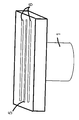
- FIG. 3 is a diagram showing details of the head unit 1 according to the present invention.
- the head unit 1 includes a fluid tank 2 that can store molten solder and the like, and a discharge head 3 provided at the lower end.
- a heating means such as a heater 4 can be attached around the abdomen of the fluid tank 2.
- the discharge head 3 has a fluid discharge nozzle 5 and a suction port 6 provided at the lower end of the head. The suction port 6 is attached so that the suction process can be performed earlier in the traveling direction than the fluid discharge nozzle 5. ing.
- the heater 4 can be attached to the lower end of the discharge head 3.
- a round shape, a slit shape, and other known shapes can be adopted.
- the suction port 6 attached to the ejection head 3 can also have a round shape, a slit shape, and other known shapes.
- a silicon wafer or a printed circuit board can be used. It is possible to remove the air in the mask 8 and the fluid that has already been ejected from a plurality of locations on the workpiece 7 such as the same.
- FIG. 4 by attaching the suction ports 6 to the front and rear of the ejection head 3, it is possible to make the deformation of the mask uniform and to perform stable reciprocal ejection.
- the fluid application apparatus of the present invention is movable in the vertical direction (Y) so as to approach and separate from the workpiece 7 of the electronic component to which the fluid is to be applied as a whole, and in the horizontal direction ( It can also be moved to X).
- a mask 8 made of polyimide or resist is placed on the work 7.
- the ejection head 3 is lowered to a position where the fluid ejection nozzle 5 contacts the workpiece 7 during fluid ejection. While the contact state between the fluid discharge nozzle 5 and the work 7 is maintained, the liquid discharge head 3 moves horizontally.
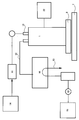
- the fluid discharge device 1 includes a heater 4 for keeping the fluid in the tank 2 at a desired temperature.
- the heater 4 may be built in the wall portion of the tank 2.
- the heater 4 is managed and controlled so that the heater 4 is heated to an appropriate temperature to maintain the optimum viscosity for the application condition of the fluid 9 such as molten solder in the tank 2.
- the fluid discharge device 1 is connected to the pressure supply means 11 capable of fluid communication from the tank 2 through the extension pipe 10, and can communicate with the fluid through the suction pipe extension pipe 12 continuing from the suction port 6.
- the decompression supply means 13 is connected.
- the pressure supply means 11 includes a pressure generation source 14 that generates nitrogen gas having a pressure of, for example, 0.06 to 0.1 MPa (not limited to this).
- the pressure generation source 14 supplies pressure into the tank 2 via the gate valve 15 and the three-way valve 16.
- the molten solder held in the tank 2 receives pressure from the pressure generation source 14 and is injected from the opening of the fluid discharge nozzle 5.
- the decompression supply means 13 has a micro ejector 16 which is a decompression generator.
- the decompression generator 16 is connected to a pressure generation source 19 that generates nitrogen gas having a pressure of 0.4 MPa (not limited to this) via, for example, a regulator 17 and a throttle valve 18, and is connected via a suction pipe extension pipe 12. Then, negative pressure is supplied to the suction port 6.
- the fluid ejection device has a pressure sensor 20 and a control device 21.
- the pressure sensor 20 is connected to a three-way valve 18 provided in the extension pipe 17 that is in fluid communication with the inside of the tank 2, and monitors the pressure in the tank 2.
- a signal indicating the pressure in the tank 2 is sent from the pressure sensor 20 to the control device 21.
- the control device 21 operates the pressure generation source 14, the decompression generation device 16, the regulator 17, the pressure generation source 19, and each valve in accordance with the progress of the work process to supply pressure into the tank 2.
- An appropriate pressure value to be supplied is determined based on a signal from the pressure sensor 20.
- the magnitude of the positive pressure supplied into the tank 2 can be changed, for example, by adjusting the pressure value generated by the pressure generation source 14 by the control device 21.
- the control device 21 may adjust the pressure value by adjusting a regulating valve (not shown) provided in the pressure supply means 11.
- An appropriate pressure value to be supplied into the tank 2 in order to inject a fluid such as molten solder from the opening of the fluid discharge nozzle 5 or hold it in the tank 2 is the molten solder contained in the tank 2. It depends on the amount (weight). Therefore, the control device 21 may receive data related to the amount of fluid in the tank 2. In this case, the control device 21 can calculate a pressure value in the tank appropriate for the injection of the fluid or the retention in the tank from the data of the fluid amount in the tank 2. Further, the control device 21 compares the appropriate tank internal pressure value with the actual tank internal pressure value indicated by the signal from the pressure sensor 20 so that the appropriate tank internal pressure can be obtained. The valve can be adjusted.
- the fluid supply device 22 may be connected to the tank 2 in order to minimize the fluctuation of the appropriate tank pressure value due to the fluctuation of the fluid amount in the tank 2 as much as possible.
- the fluid supply device 22 can automatically supply additional fluid so that the amount of fluid in the tank 2 is always substantially constant when the molten solder in the tank 2 is consumed during operation of the fluid discharge device. Any known technique can be used to know the amount of fluid in the tank 2. If the amount of molten solder in the tank 2 can be estimated from the number of processed products, etc., and the appropriate pressure value in the tank corresponding to the amount of fluid in the tank can be known by experience, control The device 21 can control the pressure to be supplied into the tank 2 based only on the signal from the pressure sensor 20.
- the discharge head 3 of the first embodiment is fixed at a fixed position away from the work 7, when the fluid is discharged, the discharge head 3 also moves in the vertical direction and the horizontal direction.
- the mask 8 is lowered to a position in contact with the ejection portion of the mask 8.
- the pressure supplied from the pressure generation source 14 supplies the pressure into the tank 2 through the gate valve 15.
- the fluid 9 held in the tank 2 receives pressure from the pressure generation source 14 and is ejected from the opening of the discharge nozzle 5.
- the discharge head 3 that is surely discharging the fluid 9 moves horizontally first from the side where the suction nozzle 5 is installed and depressurizes the air in the opening of the mask 8 on the work 7.
- the discharge head 3 moves so as to discharge the fluid.
- the return discharge head 3 is moved this time, and the discharge head 3 completes the reciprocating movement.
- the ejection head 3 performs a reciprocating operation with respect to the workpiece 7 and ejects the fluid, whereby the deformation of the mask is not biased in one direction and the deformation of the mask is reduced.
- Second embodiment Hereinafter, the second embodiment of the present invention will be described focusing on differences from the first embodiment. Of the configuration of the second embodiment, the points not particularly noted are the same as those of the first embodiment.
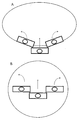
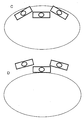
- FIG. 7A is an example showing a state in which a plurality of head portions 1 are lowered when fluid is discharged onto a silicon wafer. It has three head parts 1, the central head part is parallel to the traveling direction, and the left and right head parts are arranged along a circular workpiece and are not parallel to the traveling direction. It is.
- the left head When the head is lowered from the initial position, the left head is rotated 10 to 60 degrees clockwise, the center head is parallel to the workpiece, and the right head is rotated 10 to 60 degrees counterclockwise. It is held in the state.
- the tip of the left and right head part on the center side of the work is arranged forward in the traveling direction from the head part 1 arranged in the center, and when the head moves horizontally toward the progress report, The head portion turns counterclockwise, and the right head portion turns clockwise and approaches parallel to the traveling direction.
- FIG. 7B shows an example in which three head portions 1 are in the vicinity of the center portion of the silicon wafer.
- the central and left and right head portions 1 are all parallel to the traveling direction.
- the left head portion turns counterclockwise and the right head portion turns clockwise.
- FIG. 8C shows a state where the final position has been reached. In the final position, the left head is rotated 10 to 60 degrees counterclockwise, the center head is parallel to the workpiece, and the right head is rotated 10 to 60 degrees clockwise. Has been.
- FIG. 8D shows a state in which three head portions are moved to the outside of the silicon wafer in order to remove the mask. In this position, as in FIG. 8C, the central head portion is parallel to the traveling direction, and the left and right head portions are disposed along the circular workpiece and are not parallel to the traveling direction.
- the tips of the left and right head portions on the center side of the work are arranged forward in the direction of travel from the head portion arranged in the center.
- the left and right head portions of the fluid ejection device of the present application can move from the initial position to the final position, and can turn toward the outer periphery on the workpiece by 10 to 60 degrees.
- the ejection head 3 that is ejecting the fluid 9 moves horizontally first from the side where the suction nozzle 5 is installed, and depressurizes the air in the opening of the mask 8 on the workpiece 7.
- the ejection head 3 moves so that the fluid is ejected by the ejection nozzle 5.
- the pressure supplied from the pressure generation source 14 supplies the pressure into the tank 2 through the gate valve 15.
- the fluid 9 held in the tank 2 receives pressure from the pressure generation source 14 and is ejected from the opening of the discharge nozzle 5.
- the ejection head 3 traces over the mask 8 of the work 7 and moves horizontally to complete the application of a predetermined range of fluid. According to such an operation, by discharging the fluid using a plurality of discharge heads 3 smaller than the size of the work 7, variation in the discharge amount can be suppressed and the discharge amount can be stabilized.
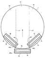
- FIG. 9 shows the initial positions of the ejection heads 3a to 3c before scanning.
- the first discharge head 3 a is disposed outside the work 7.
- the longitudinal direction of the first ejection head 3a is perpendicular to the traveling direction of the first ejection head 3a (the direction toward the upper side of the paper).
- the second ejection heads 3 b and 3 c are arranged so as to contact the inner periphery of the circular workpiece 7. In other words, the second ejection heads 3b and 3c are disposed in front of the first ejection head 3a in the traveling direction.
- the longitudinal direction of the second ejection heads 3b and 3c is inclined with respect to the traveling direction of the ejection heads 3a to 3c (the direction toward the upper side of the sheet). This inclination may be, for example, an angle of 10 to 60 degrees with respect to the traveling direction.
- the second discharge head 3b turns counterclockwise as it advances in the direction of travel, and the second discharge head 3c turns clockwise as it advances in the direction of travel.
- the operation of the second ejection heads 3b and 3c to advance in the traveling direction while turning can be realized by, for example, a robot arm.
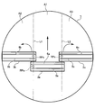
- FIG. 10 shows an intermediate position during scanning of the ejection heads 3a to 3c.
- the first ejection head 3 a moves linearly from the initial position shown in FIG. 9 to the center of the workpiece 7.
- the reference point RPa of the first ejection head 3a moves along the straight line L1.
- the second ejection heads 3b and 3c are arranged at the same arrangement angle as the first ejection head 3a by proceeding in the traveling direction while turning from the initial position shown in FIG. That is, the longitudinal direction of the first ejection head 3a is parallel to the longitudinal direction of the second ejection heads 3b and 3c. In this turning movement, the reference points RPb and RPc of the second ejection heads 3b and 3c move along the straight lines L1 and L2, respectively.
- the reference points RPb and RPc are set at the end of the discharge nozzle 5 on the first discharge head 3a side.
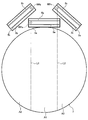
- FIG. 11 shows the final position after the scanning of the ejection heads 3a to 3c.
- the first ejection head 3a has moved from the intermediate position shown in FIG. 10 to a position outside the workpiece 7 (outside opposite to the initial position).
- the second ejection heads 3b and 3c are inclined with respect to the traveling direction of the ejection heads 3a to 3c (the direction toward the upper side of the sheet) by moving from the intermediate position shown in FIG. 10 in the traveling direction while turning. Yes.
- This inclination is an inclination opposite to the inclination at the initial position. This inclination may be, for example, an angle of 10 to 60 degrees with respect to the traveling direction.
- the fluid 9 can be applied to almost the entire region of the work 7 by moving the ejection heads 3a to 3c.
- the application in the central area A1 is covered by the first discharge head 3a
- the application in the left area A2 is covered by the left second discharge head 3b
- the right second discharge head 3c is covered.
- Application in the right region A3 is covered.
- FIG. 3 is a schematic diagram showing a schematic configuration of a solder bump forming apparatus as an example of a fluid applying apparatus according to the third embodiment.
- the solder bump forming apparatus is an apparatus that forms a solder bump by applying a fluid 9 (molten solder in this case) onto a workpiece 7 (for example, a silicon wafer or a printed board) of an electronic component.
- the solder bump forming apparatus includes an ejection head unit 1, a pressure supply unit 11, a pressure generation source 14, a micro ejector 16, a pressure generation source 19, and a fluid supply device 22.
- the solder bump forming apparatus includes stages 30 to 32 (see FIG. 12). Details of these will be described later.
- FIG. 5 is a schematic view showing the discharge head portion 1 of the solder bump forming apparatus.
- the discharge head unit 1 includes a fluid tank 2 that can store a fluid 9 and a discharge head 3 provided at the lower end thereof.
- the discharge head unit 1 is configured to be movable in the horizontal direction above the workpiece 7 by an arbitrary actuator (not shown).
- the ejection head unit 1 moves slidably on the mask 8 disposed on the workpiece 7.
- the mask 8 has a plurality of holes formed at locations where solder bumps are to be formed. These holes penetrate the mask 8 in the thickness direction (vertical direction).
- the mask 8 may be formed of, for example, polyimide or resist.
- the discharge head unit 1 is configured to be movable in the vertical direction, that is, so as to approach and leave the workpiece 7.
- the fluid tank 2 may be connected to a fluid supply device 22 as shown in FIG.
- the fluid supply device 22 can automatically replenish the fluid 9 so that the amount of the fluid stored in the fluid tank 2 is always substantially constant. According to this configuration, it is possible to suppress fluctuations in pressure in the tank due to fluctuations in the amount of fluid stored in the fluid tank 2.
- the discharge head unit 1 includes a heater 4 for keeping the fluid 9 in the tank 2 at a desired temperature.
- the heater 4 may be built in the wall portion of the tank 2.
- the heater 4 is controlled so as to heat the fluid 9 to an appropriate temperature to maintain the optimum viscosity for the application condition of the fluid 9 in the tank 2.
- the discharge head 3 has a discharge nozzle 5 and a suction port 6.
- the discharge nozzle 5 penetrates the discharge head 3 in the vertical direction and communicates with the fluid tank 2.
- the fluid tank 2 is connected to the pressure supply means 11 via the extension pipe 10.
- the pressure supply means 11 includes a pressure generation source 14 that generates nitrogen gas having a pressure of, for example, 0.06 to 0.1 MPa (not limited to this).
- the pressure generation source 14 supplies pressure to the discharge head unit 1 via a gate valve and a three-way valve. Due to this pressure, the fluid 9 in the fluid tank 2 is discharged from the discharge nozzle 5.
- the suction port 6 penetrates the ejection head 3 in the vertical direction and communicates with the suction pipe extension pipe 12.
- the suction pipe extension pipe 12 is connected to the decompression supply means 13.
- the reduced pressure supply means 13 includes a micro ejector 16 that is a reduced pressure generator.
- the micro ejector 16 is connected to a pressure generation source 19 that generates nitrogen gas having a pressure of 0.4 MPa (not limited to this) via, for example, a regulator and a throttle valve 18.
- this reduced pressure supply means 13 negative pressure is supplied to the suction port 6 through the suction pipe extension pipe 12.
- the suction port 6 is disposed in front of the discharge nozzle 5 in the traveling direction of the discharge head unit 1. For this reason, before the fluid is discharged from the discharge nozzle 5, the inside of the hole of the mask 8 can be deaerated and decompressed from the suction port 6. Thereby, the same amount of fluid can be discharged stably.
- the opening shape of the discharge nozzle 5 As the opening shape of the discharge nozzle 5, a round shape, a slit shape, and other known shapes can be employed. In particular, when a slit shape is employed as the opening shape of the discharge nozzle 5, it becomes possible to simultaneously discharge fluid into the plurality of holes of the mask 8.
- the opening shape of the suction port 6 may be a round shape, a slit shape, or other known shapes. When a slit shape is employed as the opening shape of the suction port 6, air or fluid that has already been discharged can be sucked simultaneously at a plurality of locations.
- the ejection head unit 1 is lowered to a position where the ejection head 3 (that is, the opening located at the lower end of the ejection nozzle 5) contacts the mask 8 during fluid ejection.
- the ejection head 3 moves in the horizontal direction while maintaining the contact state between the ejection nozzle 5 and the mask 8.
- air in the hole of the mask 8 disposed on the work 7 is first sucked from the suction port 6 disposed in front of the ejection head 3 in the traveling direction.
- the ejection head 3 scans the same hole a plurality of times, the fluid 9 previously ejected into the hole is also sucked at this stage.
- a heater may be disposed below the discharge head 3. By so doing, the fluid 9 previously ejected into the hole portion does not solidify, so that the fluid can be reliably aspirated.
- the ejection head 3 is further moved horizontally, the fluid 9 is ejected from the opening of the ejection nozzle 5 into the hole of the mask 8 after the suction is performed by the suction port 6. As a result, the fluid 9 is applied in the hole of the mask 8 on the workpiece 7.
- the ejection head 3 is lifted away from the mask 8. Even when the mask 8 is not used, the same process can be performed.
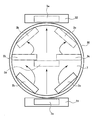
- FIG. 12 is a top view showing the arrangement of the ejection head unit 1, the first stage stage 30, and the second stages 31 and 32.
- the solder bump forming apparatus of this embodiment includes three ejection heads 3a to 3c. In practice, three ejection head portions 1 are also provided, but these are not shown in FIG. Also, the mask 8 is not shown.
- the discharge head 3a is also called the first discharge head 3a
- the discharge heads 3b and 3c are also called the second discharge heads 3b and 3c.
- the solder bump forming apparatus includes a first stage stage 30 for supporting the work 7 and second stages 31 and 32 arranged outside the first stage stage 30.
- the first stage stage 30 has a circular shape slightly larger than the circular workpiece 7.
- the shape of the first stage stage 30 may have any shape depending on the shape of the workpiece 7.
- the second stages 31 and 32 are arranged to face both ends in the radial direction of the first stage stage 30 so as to come into contact with the outer edge of the first stage stage 30.
- the second stages 31 and 32 have a rectangular shape.
- the second stages 31 and 32 may have any shape that extends to the outer edge of the first stage stage 30.
- the second stages 31 and 32 may have a concave shape having an arc that matches the arc shape of the outer edge of the first stage stage 30.
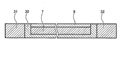
- FIG. 13 is a cross-sectional view showing the arrangement of the first stage stage 30 and the second stages 31 and 32.
- the first stage stage 30 has a recess for placing the workpiece 7 at the center thereof.
- the recess is formed in such a size that the upper end of the recess coincides with the upper end of the mask 8 when the workpiece 7 and the mask 8 are disposed in the recess.
- the upper ends of the second stages 31 and 32 are at the same height as the upper end of the concave portion of the first stage stage 30 and the upper end of the mask 8. Accordingly, the first discharge head 3a described later can be slidably moved in the horizontal direction while being in contact with the upper surfaces of the stages 30 to 32 and the mask 8.
- the first discharge head 3a is configured to move in the horizontal direction above the workpiece 7. Specifically, the first ejection head 3a is moved from an initial position outside the first stage stage 30 (position on the second stage 31) to a final position outside the first stage stage 30 (second position). It moves linearly through the center of the workpiece 7 to a position on the stage 32).
- the second ejection heads 3b and 3c are respectively arranged on both sides of the first ejection head 3a.
- the second ejection heads 3b and 3c move above the workpiece 7 in the same traveling direction as the first ejection head 3a while changing the arrangement angle.
- the width in the longitudinal direction of the discharge heads 3a to 3c is the width of the work 7 (in other words, the region in which the work 7 is disposed). Smaller than. For this reason, the ejection heads 3 a to 3 c cooperate with each other to apply the fluid 9 to the entire area of the workpiece 7. In other words, the fluid 9 is applied to the entire region of the work 7 by applying the fluid 9 to different regions of the ejection heads 3a to 3c.
- the width of the ejection heads 3a to 3c may be 1 ⁇ 4 or more and 1 ⁇ 2 or less of the width of the region where the work 7 is arranged. In this way, the fluid 9 can be uniformly applied without excessively complicating the apparatus configuration.
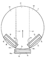
- FIG. 14 shows the initial positions of the ejection heads 3a to 3c before scanning.
- the first ejection head 3a is disposed on the second stage 31 (not shown in FIG. 14).
- the longitudinal direction of the first ejection head 3a is perpendicular to the traveling direction of the first ejection head 3a (the direction toward the upper side of the paper).
- the second ejection heads 3 b and 3 c are arranged so as to contact the inner periphery of the circular workpiece 7. In other words, the second ejection heads 3b and 3c are disposed in front of the first ejection head 3a in the traveling direction.
- the longitudinal direction of the second ejection heads 3b and 3c is inclined with respect to the traveling direction of the ejection heads 3a to 3c (the direction toward the upper side of the sheet). This inclination may be, for example, an angle of 10 to 60 degrees with respect to the traveling direction.
- the second discharge head 3b turns counterclockwise as it advances in the direction of travel, and the second discharge head 3c turns clockwise as it advances in the direction of travel.
- the operation of the second ejection heads 3b and 3c to advance in the traveling direction while turning can be realized by, for example, a robot arm.
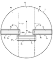
- FIG. 15 shows an intermediate position during scanning of the ejection heads 3a to 3c.
- the first ejection head 3 a moves linearly from the initial position shown in FIG. 14 to the center of the workpiece 7.
- the reference point RPa of the first ejection head 3a moves along the straight line L1.
- the second discharge heads 3b and 3c are arranged at the same arrangement angle as that of the first discharge head 3a by moving in the advancing direction while turning from the initial position shown in FIG. That is, the longitudinal direction of the first ejection head 3a is parallel to the longitudinal direction of the second ejection heads 3b and 3c. In this turning movement, the reference points RPb and RPc of the second ejection heads 3b and 3c move along the straight lines L1 and L2, respectively.
- the reference points RPb and RPc are set at the end of the discharge nozzle 5 on the first discharge head 3a side.
- FIG. 16 shows the final position after the scanning of the ejection heads 3a to 3c.
- the first ejection head 3a has moved from the intermediate position shown in FIG. 15 to a position on the second stage 32 (not shown in FIG. 16).
- the second ejection heads 3b and 3c are inclined with respect to the traveling direction of the ejection heads 3a to 3c (the direction toward the upper side of the sheet) by moving from the intermediate position shown in FIG. 15 in the traveling direction while turning. Yes.
- This inclination is an inclination opposite to the inclination at the initial position. This inclination may be, for example, an angle of 10 to 60 degrees with respect to the traveling direction.
- the fluid 9 can be applied to almost the entire region of the work 7 by moving the ejection heads 3a to 3c.
- the application in the central area A1 is covered by the first discharge head 3a
- the application in the left area A2 is covered by the left second discharge head 3b
- the right second discharge head 3c is covered.
- Application in the right region A3 is covered.
- the movement of the ejection heads 3a to 3c described above may be performed simultaneously in synchronization with each other. By doing so, the processing time of the workpiece 7 can be shortened. However, after at least one movement of the ejection heads 3a to 3c is completed, the remaining ejection heads 3a to 3c may start to move.
- the solder bump forming apparatus since the fluid 9 is discharged using a plurality of discharge heads 3a to 3c smaller than the size of the work 7, even if the work 7 is large, the discharge heads 3a to 3c The pressure applied to the work 7 from each of them is distributed almost evenly. Therefore, the discharge amount of the fluid 9 can be made uniform.
- the second stages 31 and 32 are arranged on the moving path of the first ejection head 3 a outside the first stage stage 30, the first ejection head 3 a is separated from the outer edge of the work 7. Application to the outer edge is possible.
- the second ejection heads 3b and 3c move while changing the arrangement angle, the fluid 9 can be ejected over a wide range even when application is started from a position on the workpiece 7. Therefore, the fluid 9 can be discharged over a wide area of the work 7.
- the fluid can be efficiently used for almost the entire area of the circular workpiece 7. Can be applied.
- the number of ejection heads 3 can be an arbitrary number of 2 or more depending on the size and shape of the workpiece 7.
Abstract
Description
まず、流体塗布装置のヘッド部1の構成を説明する。図3が本発明によるヘッド部1の詳細を示す図である。ヘッド部1は、溶融はんだ等を収容可能な流体タンク2と、下端に設けた吐出ヘッド3と、を備える。溶融はんだなど温度コントロールが必要な流体に用いるときは、流体タンク2の腹部にヒータ4を巻き付けるなど、加熱手段を取り付けることもできる。吐出ヘッド3には、ヘッド下端に設けた流体吐出ノズル5と吸引口6とを有し、吸引口6は流体吐出ノズル5よりも進行方向に向かって先に吸引工程が実施できるように取り付けられている。流体吐出ノズル5及び吸引口6にも温度コントロールが必要な流体に用いるときは、吐出ヘッド3下端にもヒータ4を取り付けることが可能となる。
以下、本発明の第2実施形態について、第1実施形態と異なる点を中心に説明する。第2の実施形態の構成のうち、特に断らない点については、第1実施形態と同じである。
以下、本発明の第3実施形態について説明する。図3は、第3実施形態による流体塗布装置の一例としてのはんだバンプ形成装置の概略構成を示す模式図である。はんだバンプ形成装置は、電子部品のワーク7(例えば、シリコンウエハやプリント基板等)上に流体9(ここでは、溶融はんだ)を塗布して、はんだバンプを形成する装置である。図3に示すように、はんだバンプ形成装置は、吐出ヘッド部1と、圧力供給手段11と、圧力発生源14と、マイクロエジェクタ16と、圧力発生源19と、流体供給装置22と、を備えている。また、はんだバンプ形成装置は、ステージ30~32を備えている(図12参照)。これらの詳細については後述する。
2…流体タンク
3,3a,3b,3c…吐出ヘッド
4…ヒータ
5…吐出ノズル
6…吸引口
7…ワーク
8…マスク
9…流体
10…延長管路
11…圧力供給手段
12…吸引管延長管路
13…減圧供給手段
14…圧力発生源
16…マイクロエジェクタ
18…絞り弁
19…圧力発生源
22…流体供給装置
30…第1のステージステージ
31,32…第2のステージ
Claims (18)
- 電子部品のワーク上のマスク中に流体を塗布するための流体吐出方法であって、流体を収容可能なタンクと吐出ヘッドからなる、ワークの長さより短い幅のヘッド部を有し、前記吐出ヘッドには、ワーク上のマスクの内容物を吸引するための吸引口とその近傍には流体を吐出するための吐出ノズルが形成されており、かつ吸引口は、吐出ヘッドの進行方向の前方に設置されている流体吐出装置を用い、ワークに対して吐出ヘッドを往復することで吐出を行う、流体の吐出方法。
- 請求項1に記載の流体吐出方法において、前記吐出ヘッドには、吐出ノズルおよび吸引口の形状としてスリット状の開口部を有することを特徴とする流体吐出方法。
- 請求項1に記載の流体吐出方法において、前記吐出ヘッドには、吐出ノズルを挟んで吸引口が両側に配置されていることを特徴とする流体吐出方法。
- 請求項1に記載の流体吐出方法において、前記吐出ヘッドには、吐出ノズルおよび吸引口の近傍にヒータが設置されていることを特徴とする流体吐出方法。
- 電子部品のワーク上のマスク中に流体を塗布するための流体吐出装置であって、流体を収容可能なタンクと吐出ヘッドからなる、ワークの長さより短い幅のヘッド部であって、前記吐出ヘッドには、流体を吐出するための吐出ノズルの近傍に、ワーク上のマスクの内容物を吸引するためのスリット状の開口部を有する吸引口が吐出ノズルを挟んで吸引口が両側に配置していることを特徴とする流体吐出装置。
- 電子部品のワーク上マスク中に流体を塗布するための流体吐出方法であって、
前記流体を吐出するための吐出ノズルが形成され、前記ワークの長さより短い幅を有する吐出ヘッドを前記ワークに対して往復移動させつつ、前記吐出ノズルから前記流体を吐出することによって、前記マスク中に前記流体を塗布する工程を備える
流体吐出方法。 - 電子部品のワーク上のマスク中に流体を塗布するための流体吐出装置であって、流体を収容可能なタンクと吐出ヘッドからなる、ワークより小さく、角度が可変可能な複数のヘッド部を有し、前記ヘッド部はお互いに同期してワーク上の水平方向に移動し、前記吐出ヘッドには、ワーク上のマスクの内容物を吸引するための吸引口とその近傍には流体を吐出するための吐出ノズルが形成されており、かつ吸引口は、吐出ヘッドの進行方向の前方に設置されていることを特徴とする流体吐出装置。
- 請求項7に記載の流体吐出装置において、ワークより小さな複数のヘッド部の数が2~4個であることを特徴とする流体吐出装置。
- 請求項7に記載の流体吐出装置において、前記吐出ヘッドには、吐出ノズルを挟んで吸引口が両側に配置されていることを特徴とする流体吐出装置。
- 請求項7に記載の流体吐出装置において、前記吐出ヘッドには、吐出ノズルおよび吸引口の近傍にヒータが設置されていることを特徴とする流体吐出装置。
- 請求項7に記載の流体吐出装置を用い、吐出ヘッドが複数回ワークを移動する事により、まず吸引口でマスク中の空気もしくは既に吐出した流体を吸入し、その後ワークに流体を充填する事を特徴とする流体吐出方法。
- 電子部品のワーク上に流体を塗布するための流体吐出装置であって、
前記ワークを支持するためのステージと、
前記ステージの上方を水平方向に直線的に移動しながら前記流体を吐出するように構成された第1の吐出ヘッドであって、前記第1のステージの外部の初期位置から、前記ステージの上方を経由して、前記ステージの外部の最終位置まで移動するように構成された第1の吐出ヘッドと、
配置角度を変えつつ前記ステージの上方を水平方向に移動しながら前記流体を吐出するように構成された第2の吐出ヘッドと、
を備え、
前記第1の吐出ヘッドおよび前記第2の吐出ヘッドにおける前記流体を吐出可能な範囲は、ステージ上の前記ワークを配置する領域の幅よりも小さく、
前記第2の吐出ヘッドには、該第2の吐出ヘッドに形成された吐出ノズルの前記第1の吐出ヘッド側の端部に基準点が設定され、
前記基準点は、前記第2の吐出ヘッドが移動する際に、前記第2の吐出ヘッドの移動方向に沿った直線的な経路を描く
流体吐出装置。 - 電子部品のワーク上に流体を塗布するための流体吐出装置であって、
前記ワークを支持するためのステージと、
前記ステージの上方を水平方向に直線的に移動しながら前記流体を吐出するように構成された第1の吐出ヘッドであって、前記第1のステージの外部の初期位置から、前記ステージの上方を経由して、前記ステージの外部の最終位置まで移動するように構成された第1の吐出ヘッドと、
配置角度を変えつつ前記ステージの上方を水平方向に移動しながら前記流体を吐出するように構成された第2の吐出ヘッドと、
を備え、
前記第1の吐出ヘッドおよび前記第2の吐出ヘッドにおける前記流体を吐出可能な範囲は、ステージ上の前記ワークを配置する領域の幅よりも小さい
流体吐出装置。 - 電子部品のワーク上に流体を塗布するための流体吐出装置であって、
前記ワークを支持するための第1のステージと、
前記ワークの上方を水平方向に直線的に移動しながら前記流体を吐出するように構成された第1の吐出ヘッドであって、前記第1のステージの外部の初期位置から、前記第1のステージの上方を経由して、前記第1のステージの外部の最終位置まで移動するように構成された第1の吐出ヘッドと、
配置角度を変えつつ前記第1のステージの上方を水平方向に移動しながら前記流体を吐出するように構成された第2の吐出ヘッドと、
前記第1の吐出ヘッドの移動経路上において、前記初期位置から前記第1のステージの外縁まで、および、前記第1のステージの外縁から前記最終位置まで配置された第2のステージであって、前記吐出ヘッドが前記第2のステージ上を摺動可能に配置された第2のステージと
を備え、
前記第1の吐出ヘッドおよび前記第2の吐出ヘッドにおける前記流体を吐出可能な範囲は、第1のステージ上の前記ワークを配置する領域の幅よりも小さい
流体吐出装置。 - 請求項14に記載の流体吐出装置であって、
前記第2の吐出ヘッドは、2つの吐出ヘッドを備え、
前記2つの吐出ヘッドは、前記第1の吐出ヘッドの両側に1つずつ配置された
流体吐出装置。 - 請求項14または請求項15に記載の流体吐出装置であって、
前記第1の吐出ヘッドおよび前記第2の吐出ヘッドは、同期して同時に移動するように構成された
流体吐出装置。 - 請求項14ないし請求項16のいずれか一項に記載の流体吐出装置であって、
前記第1の吐出ヘッドおよび前記第2の吐出ヘッドは、互いに協働して、前記ワークの被吐出領域を実質的に重複することなくカバーするように構成された
流体吐出装置。 - 請求項14ないし請求項17のいずれか一項に記載の流体吐出装置であって、
前記第1の吐出ヘッドおよび前記第2の吐出ヘッドにおける前記流体を吐出可能な範囲は、第1のステージ上の前記ワークを配置する領域の幅の1/4以上、1/2以下である
流体吐出装置。
Priority Applications (6)
| Application Number | Priority Date | Filing Date | Title |
|---|---|---|---|
| KR1020187020103A KR102596840B1 (ko) | 2015-12-15 | 2016-12-15 | 유체 토출 장치 및 유체 토출 방법 |
| EP16875722.7A EP3391974B1 (en) | 2015-12-15 | 2016-12-15 | Fluid discharge device and method for discharging fluid |
| CN201680074153.8A CN108602088B (zh) | 2015-12-15 | 2016-12-15 | 流体排出装置及流体排出方法 |
| JP2017556439A JP6579343B2 (ja) | 2015-12-15 | 2016-12-15 | 流体吐出装置および流体吐出方法 |
| US16/063,155 US10932372B2 (en) | 2015-12-15 | 2016-12-15 | Fluid discharge device |
| US17/153,978 US11259415B2 (en) | 2015-12-15 | 2021-01-21 | Method for discharging fluid |
Applications Claiming Priority (6)
| Application Number | Priority Date | Filing Date | Title |
|---|---|---|---|
| JP2015244139 | 2015-12-15 | ||
| JP2015-244141 | 2015-12-15 | ||
| JP2015-244139 | 2015-12-15 | ||
| JP2015244141 | 2015-12-15 | ||
| JP2016165458 | 2016-08-26 | ||
| JP2016-165458 | 2016-08-26 |
Related Child Applications (2)
| Application Number | Title | Priority Date | Filing Date |
|---|---|---|---|
| US16/063,155 A-371-Of-International US10932372B2 (en) | 2015-12-15 | 2016-12-15 | Fluid discharge device |
| US17/153,978 Division US11259415B2 (en) | 2015-12-15 | 2021-01-21 | Method for discharging fluid |
Publications (1)
| Publication Number | Publication Date |
|---|---|
| WO2017104745A1 true WO2017104745A1 (ja) | 2017-06-22 |
Family
ID=59056589
Family Applications (1)
| Application Number | Title | Priority Date | Filing Date |
|---|---|---|---|
| PCT/JP2016/087369 WO2017104745A1 (ja) | 2015-12-15 | 2016-12-15 | 流体吐出装置および流体吐出方法 |
Country Status (8)
| Country | Link |
|---|---|
| US (2) | US10932372B2 (ja) |
| EP (1) | EP3391974B1 (ja) |
| JP (2) | JP6579343B2 (ja) |
| KR (1) | KR102596840B1 (ja) |
| CN (1) | CN108602088B (ja) |
| HU (1) | HUE059602T2 (ja) |
| TW (2) | TWI708346B (ja) |
| WO (1) | WO2017104745A1 (ja) |
Families Citing this family (2)
| Publication number | Priority date | Publication date | Assignee | Title |
|---|---|---|---|---|
| US11298769B2 (en) * | 2019-05-13 | 2022-04-12 | International Business Machines Corporation | Prevention of dripping of material for material injection |
| CN116390372A (zh) * | 2021-10-13 | 2023-07-04 | 苏州康尼格电子科技股份有限公司 | Pcba板封装方法及封装设备 |
Citations (19)
| Publication number | Priority date | Publication date | Assignee | Title |
|---|---|---|---|---|
| JPS55154798A (en) * | 1979-05-21 | 1980-12-02 | Sony Corp | Apparatus for fabricating hybrid integrated circuit |
| JPH0215698A (ja) * | 1988-04-15 | 1990-01-19 | Internatl Business Mach Corp <Ibm> | はんだ付着装置 |
| JPH06151296A (ja) * | 1992-11-11 | 1994-05-31 | Yamaha Corp | 加圧塗布方法及び装置 |
| JPH07202399A (ja) * | 1993-12-21 | 1995-08-04 | Internatl Business Mach Corp <Ibm> | キャリアに部品を接続する接合剤を塗布するための方法およびノズル,並びに接合剤が塗布された回路基板 |
| JP2001269610A (ja) * | 2000-01-17 | 2001-10-02 | Canon Inc | 塗布方法、塗布装置および被膜の作製方法 |
| JP2002260985A (ja) * | 2001-03-01 | 2002-09-13 | Dainippon Screen Mfg Co Ltd | 基板現像装置 |
| JP2003249440A (ja) * | 2002-02-26 | 2003-09-05 | Seiko Epson Corp | 薄膜形成装置と薄膜形成方法、回路パターンの製造装置と回路パターンの製造方法と電子機器、及びレジストパターンの製造装置とレジストパターンの製造方法 |
| JP2004122021A (ja) * | 2002-10-03 | 2004-04-22 | Seiko Epson Corp | 液滴吐出装置及び方法、デバイスの製造装置、デバイス製造方法、並びに電子機器 |
| JP2004223339A (ja) * | 2003-01-20 | 2004-08-12 | Seiko Epson Corp | 液滴吐出装置、電気光学装置、電気光学装置の製造方法および電子機器 |
| JP2004337704A (ja) * | 2003-05-14 | 2004-12-02 | Seiko Epson Corp | 液滴吐出装置 |
| JP2005183542A (ja) * | 2003-12-17 | 2005-07-07 | Fujikura Ltd | プリント配線板のはんだコーティング方法 |
| JP2006013228A (ja) * | 2004-06-28 | 2006-01-12 | Toshiba Corp | 基板処理方法及び基板処理装置 |
| JP2006080403A (ja) * | 2004-09-10 | 2006-03-23 | Tokyo Electron Ltd | 塗布、現像装置、レジストパターン形成方法、露光装置及び洗浄装置 |
| JP2012139655A (ja) * | 2011-01-05 | 2012-07-26 | Seiko Epson Corp | 印刷装置 |
| WO2013058299A1 (ja) * | 2011-10-18 | 2013-04-25 | 千住金属工業株式会社 | はんだバンプ形成方法および装置 |
| JP2014091222A (ja) * | 2012-10-31 | 2014-05-19 | Yamaha Motor Co Ltd | 半田供給方法、半田供給装置 |
| JP2014157863A (ja) * | 2013-02-14 | 2014-08-28 | Tokyo Electron Ltd | 金属ペースト充填方法及び金属ペースト充填装置 |
| JP2015054269A (ja) * | 2013-09-11 | 2015-03-23 | 東レエンジニアリング株式会社 | エレクトロスプレー装置 |
| WO2016114275A1 (ja) * | 2015-01-13 | 2016-07-21 | 千住金属工業株式会社 | 流体吐出装置、流体吐出方法、及び流体塗布装置 |
Family Cites Families (29)
| Publication number | Priority date | Publication date | Assignee | Title |
|---|---|---|---|---|
| US4517917A (en) * | 1984-04-26 | 1985-05-21 | Valco Cincinnati, Inc. | Blow-off manifold for preventing trailing from a non-contact extrusion adhesive application valve |
| US4934309A (en) | 1988-04-15 | 1990-06-19 | International Business Machines Corporation | Solder deposition system |
| US5418009A (en) * | 1992-07-08 | 1995-05-23 | Nordson Corporation | Apparatus and methods for intermittently applying discrete adhesive coatings |
| US6231333B1 (en) * | 1995-08-24 | 2001-05-15 | International Business Machines Corporation | Apparatus and method for vacuum injection molding |
| US6149076A (en) * | 1998-08-05 | 2000-11-21 | Nordson Corporation | Dispensing apparatus having nozzle for controlling heated liquid discharge with unheated pressurized air |
| US6461136B1 (en) * | 1999-08-26 | 2002-10-08 | International Business Machines Corp. | Apparatus for filling high aspect ratio via holes in electronic substrates |
| FI115295B (fi) * | 1999-09-01 | 2005-04-15 | Metso Paper Inc | Verhopäällystin ja verhopäällystysmenetelmä |
| FR2803228B1 (fr) * | 2000-01-03 | 2002-02-08 | Novatec Sa Soc | Dispositif de remplissage collectif de cavites borgnes |
| US6544590B1 (en) | 2000-01-17 | 2003-04-08 | Canon Kabushiki Kaisha | Liquid coating method, apparatus and film-forming method for producing the same employing excess coating removing unit having absorbent fabric on porous structure |
| US6638363B2 (en) * | 2000-11-22 | 2003-10-28 | Gunter Erdmann | Method of cleaning solder paste |
| US6692165B2 (en) * | 2001-03-01 | 2004-02-17 | Dainippon Screen Mfg. Co., Ltd. | Substrate processing apparatus |
| US20040202863A1 (en) * | 2002-02-26 | 2004-10-14 | Konica Corporation | Coating method, coated product and ink jet recording medium |
| JP3619874B2 (ja) | 2002-07-05 | 2005-02-16 | 国立大学法人京都大学 | 温度応答性ポリマー及び温度応答性ゲル状ポリマー |
| JP3772155B2 (ja) | 2003-04-01 | 2006-05-10 | 株式会社タムラ製作所 | 液体噴射装置 |
| KR100958573B1 (ko) * | 2003-10-06 | 2010-05-18 | 엘지디스플레이 주식회사 | 액정표시패널의 제조장치 및 제조방법 |
| JP2005246139A (ja) | 2004-03-01 | 2005-09-15 | Seiko Epson Corp | 流動材料塗布方法、流動材料塗布装置および電子機器 |
| US7354869B2 (en) | 2004-04-13 | 2008-04-08 | Kabushiki Kaisha Toshiba | Substrate processing method, substrate processing apparatus, and semiconductor device manufacturing method |
| US7291226B2 (en) * | 2004-09-30 | 2007-11-06 | Lexmark International, Inc. | Progressive stencil printing |
| KR100780718B1 (ko) * | 2004-12-28 | 2007-12-26 | 엘지.필립스 엘시디 주식회사 | 도포액 공급장치를 구비한 슬릿코터 |
| US8287647B2 (en) * | 2007-04-17 | 2012-10-16 | Lam Research Corporation | Apparatus and method for atomic layer deposition |
| US20080268164A1 (en) * | 2007-04-26 | 2008-10-30 | Air Products And Chemicals, Inc. | Apparatuses and Methods for Cryogenic Cooling in Thermal Surface Treatment Processes |
| DE102007053513B3 (de) * | 2007-11-09 | 2009-07-16 | Itc Intercircuit Electronic Gmbh | Füllanlage |
| US9987840B2 (en) * | 2010-04-05 | 2018-06-05 | Asm Assembly Systems Switzerland Gmbh | Screen cleaning apparatus and method |
| US8789490B2 (en) * | 2012-01-20 | 2014-07-29 | Sso Venture Partners, Llc | System and method of pointillist painting |
| US9427768B2 (en) * | 2012-10-26 | 2016-08-30 | Nordson Corporation | Adhesive dispensing system and method with melt on demand at point of dispensing |
| US9278401B2 (en) * | 2013-02-11 | 2016-03-08 | International Business Machines Corporation | Fill head interface with combination vacuum pressure chamber |
| JP6276552B2 (ja) * | 2013-10-04 | 2018-02-07 | ファスフォードテクノロジ株式会社 | ダイボンダ及び接着剤塗布方法 |
| EP3401951A4 (en) * | 2015-12-15 | 2019-10-30 | Senju Metal Industry Co., Ltd. | METHOD FOR CORRECTING SOLDER BOSS |
| JP2017109211A (ja) * | 2015-12-15 | 2017-06-22 | 千住金属工業株式会社 | 流体吐出方法および流体吐出装置 |
-
2016
- 2016-12-15 KR KR1020187020103A patent/KR102596840B1/ko active IP Right Grant
- 2016-12-15 CN CN201680074153.8A patent/CN108602088B/zh active Active
- 2016-12-15 WO PCT/JP2016/087369 patent/WO2017104745A1/ja active Application Filing
- 2016-12-15 JP JP2017556439A patent/JP6579343B2/ja active Active
- 2016-12-15 TW TW105141593A patent/TWI708346B/zh active
- 2016-12-15 EP EP16875722.7A patent/EP3391974B1/en active Active
- 2016-12-15 US US16/063,155 patent/US10932372B2/en active Active
- 2016-12-15 HU HUE16875722A patent/HUE059602T2/hu unknown
- 2016-12-15 TW TW109114554A patent/TWI708348B/zh active
-
2019
- 2019-05-24 JP JP2019097444A patent/JP6687874B2/ja active Active
-
2021
- 2021-01-21 US US17/153,978 patent/US11259415B2/en active Active
Patent Citations (19)
| Publication number | Priority date | Publication date | Assignee | Title |
|---|---|---|---|---|
| JPS55154798A (en) * | 1979-05-21 | 1980-12-02 | Sony Corp | Apparatus for fabricating hybrid integrated circuit |
| JPH0215698A (ja) * | 1988-04-15 | 1990-01-19 | Internatl Business Mach Corp <Ibm> | はんだ付着装置 |
| JPH06151296A (ja) * | 1992-11-11 | 1994-05-31 | Yamaha Corp | 加圧塗布方法及び装置 |
| JPH07202399A (ja) * | 1993-12-21 | 1995-08-04 | Internatl Business Mach Corp <Ibm> | キャリアに部品を接続する接合剤を塗布するための方法およびノズル,並びに接合剤が塗布された回路基板 |
| JP2001269610A (ja) * | 2000-01-17 | 2001-10-02 | Canon Inc | 塗布方法、塗布装置および被膜の作製方法 |
| JP2002260985A (ja) * | 2001-03-01 | 2002-09-13 | Dainippon Screen Mfg Co Ltd | 基板現像装置 |
| JP2003249440A (ja) * | 2002-02-26 | 2003-09-05 | Seiko Epson Corp | 薄膜形成装置と薄膜形成方法、回路パターンの製造装置と回路パターンの製造方法と電子機器、及びレジストパターンの製造装置とレジストパターンの製造方法 |
| JP2004122021A (ja) * | 2002-10-03 | 2004-04-22 | Seiko Epson Corp | 液滴吐出装置及び方法、デバイスの製造装置、デバイス製造方法、並びに電子機器 |
| JP2004223339A (ja) * | 2003-01-20 | 2004-08-12 | Seiko Epson Corp | 液滴吐出装置、電気光学装置、電気光学装置の製造方法および電子機器 |
| JP2004337704A (ja) * | 2003-05-14 | 2004-12-02 | Seiko Epson Corp | 液滴吐出装置 |
| JP2005183542A (ja) * | 2003-12-17 | 2005-07-07 | Fujikura Ltd | プリント配線板のはんだコーティング方法 |
| JP2006013228A (ja) * | 2004-06-28 | 2006-01-12 | Toshiba Corp | 基板処理方法及び基板処理装置 |
| JP2006080403A (ja) * | 2004-09-10 | 2006-03-23 | Tokyo Electron Ltd | 塗布、現像装置、レジストパターン形成方法、露光装置及び洗浄装置 |
| JP2012139655A (ja) * | 2011-01-05 | 2012-07-26 | Seiko Epson Corp | 印刷装置 |
| WO2013058299A1 (ja) * | 2011-10-18 | 2013-04-25 | 千住金属工業株式会社 | はんだバンプ形成方法および装置 |
| JP2014091222A (ja) * | 2012-10-31 | 2014-05-19 | Yamaha Motor Co Ltd | 半田供給方法、半田供給装置 |
| JP2014157863A (ja) * | 2013-02-14 | 2014-08-28 | Tokyo Electron Ltd | 金属ペースト充填方法及び金属ペースト充填装置 |
| JP2015054269A (ja) * | 2013-09-11 | 2015-03-23 | 東レエンジニアリング株式会社 | エレクトロスプレー装置 |
| WO2016114275A1 (ja) * | 2015-01-13 | 2016-07-21 | 千住金属工業株式会社 | 流体吐出装置、流体吐出方法、及び流体塗布装置 |
Non-Patent Citations (1)
| Title |
|---|
| See also references of EP3391974A4 * |
Also Published As
| Publication number | Publication date |
|---|---|
| CN108602088A (zh) | 2018-09-28 |
| KR102596840B1 (ko) | 2023-11-02 |
| US20180376600A1 (en) | 2018-12-27 |
| TWI708346B (zh) | 2020-10-21 |
| TW202034479A (zh) | 2020-09-16 |
| US20210144863A1 (en) | 2021-05-13 |
| JP6579343B2 (ja) | 2019-09-25 |
| EP3391974B1 (en) | 2022-06-01 |
| US11259415B2 (en) | 2022-02-22 |
| EP3391974A1 (en) | 2018-10-24 |
| TW201731053A (zh) | 2017-09-01 |
| US10932372B2 (en) | 2021-02-23 |
| TWI708348B (zh) | 2020-10-21 |
| JPWO2017104745A1 (ja) | 2018-11-15 |
| EP3391974A4 (en) | 2019-08-07 |
| JP6687874B2 (ja) | 2020-04-28 |
| KR20180098581A (ko) | 2018-09-04 |
| JP2019166522A (ja) | 2019-10-03 |
| CN108602088B (zh) | 2022-10-14 |
| HUE059602T2 (hu) | 2022-11-28 |
Similar Documents
| Publication | Publication Date | Title |
|---|---|---|
| JP6205678B2 (ja) | 流体吐出装置、流体吐出方法、及び流体塗布装置 | |
| KR100659362B1 (ko) | 스크린 인쇄장치 및 그의 인쇄방법 | |
| JP5014397B2 (ja) | バンプ印刷装置 | |
| US11259415B2 (en) | Method for discharging fluid | |
| JP2022009863A (ja) | スクリーン印刷機およびスクリーン印刷方法 | |
| JP7017020B2 (ja) | はんだバンプの修正方法 | |
| JP2010225968A (ja) | 電子部品実装装置 | |
| JP2017109211A (ja) | 流体吐出方法および流体吐出装置 | |
| JP2007222789A (ja) | 塗布機および実装ライン | |
| JP2011156482A (ja) | 液体塗布装置 |
Legal Events
| Date | Code | Title | Description |
|---|---|---|---|
| 121 | Ep: the epo has been informed by wipo that ep was designated in this application |
Ref document number: 16875722 Country of ref document: EP Kind code of ref document: A1 |
|
| DPE1 | Request for preliminary examination filed after expiration of 19th month from priority date (pct application filed from 20040101) | ||
| ENP | Entry into the national phase |
Ref document number: 2017556439 Country of ref document: JP Kind code of ref document: A |
|
| NENP | Non-entry into the national phase |
Ref country code: DE |
|
| ENP | Entry into the national phase |
Ref document number: 20187020103 Country of ref document: KR Kind code of ref document: A |
|
| WWE | Wipo information: entry into national phase |
Ref document number: 1020187020103 Country of ref document: KR |
|
| WWE | Wipo information: entry into national phase |
Ref document number: 2016875722 Country of ref document: EP |
|
| ENP | Entry into the national phase |
Ref document number: 2016875722 Country of ref document: EP Effective date: 20180716 |