WO2017073193A1 - ダンパ装置 - Google Patents
ダンパ装置 Download PDFInfo
- Publication number
- WO2017073193A1 WO2017073193A1 PCT/JP2016/077068 JP2016077068W WO2017073193A1 WO 2017073193 A1 WO2017073193 A1 WO 2017073193A1 JP 2016077068 W JP2016077068 W JP 2016077068W WO 2017073193 A1 WO2017073193 A1 WO 2017073193A1
- Authority
- WO
- WIPO (PCT)
- Prior art keywords
- storage
- rotating body
- elastic member
- window
- coil spring
- Prior art date
- Legal status (The legal status is an assumption and is not a legal conclusion. Google has not performed a legal analysis and makes no representation as to the accuracy of the status listed.)
- Ceased
Links
Images



Classifications
-
- F—MECHANICAL ENGINEERING; LIGHTING; HEATING; WEAPONS; BLASTING
- F16—ENGINEERING ELEMENTS AND UNITS; GENERAL MEASURES FOR PRODUCING AND MAINTAINING EFFECTIVE FUNCTIONING OF MACHINES OR INSTALLATIONS; THERMAL INSULATION IN GENERAL
- F16F—SPRINGS; SHOCK-ABSORBERS; MEANS FOR DAMPING VIBRATION
- F16F15/00—Suppression of vibrations in systems; Means or arrangements for avoiding or reducing out-of-balance forces, e.g. due to motion
- F16F15/10—Suppression of vibrations in rotating systems by making use of members moving with the system
- F16F15/12—Suppression of vibrations in rotating systems by making use of members moving with the system using elastic members or friction-damping members, e.g. between a rotating shaft and a gyratory mass mounted thereon
- F16F15/121—Suppression of vibrations in rotating systems by making use of members moving with the system using elastic members or friction-damping members, e.g. between a rotating shaft and a gyratory mass mounted thereon using springs as elastic members, e.g. metallic springs
- F16F15/123—Wound springs
- F16F15/12353—Combinations of dampers, e.g. with multiple plates, multiple spring sets, i.e. complex configurations
-
- F—MECHANICAL ENGINEERING; LIGHTING; HEATING; WEAPONS; BLASTING
- F16—ENGINEERING ELEMENTS AND UNITS; GENERAL MEASURES FOR PRODUCING AND MAINTAINING EFFECTIVE FUNCTIONING OF MACHINES OR INSTALLATIONS; THERMAL INSULATION IN GENERAL
- F16D—COUPLINGS FOR TRANSMITTING ROTATION; CLUTCHES; BRAKES
- F16D13/00—Friction clutches
- F16D13/58—Details
- F16D13/60—Clutching elements
- F16D13/64—Clutch-plates; Clutch-lamellae
- F16D13/68—Attachments of plates or lamellae to their supports
-
- F—MECHANICAL ENGINEERING; LIGHTING; HEATING; WEAPONS; BLASTING
- F16—ENGINEERING ELEMENTS AND UNITS; GENERAL MEASURES FOR PRODUCING AND MAINTAINING EFFECTIVE FUNCTIONING OF MACHINES OR INSTALLATIONS; THERMAL INSULATION IN GENERAL
- F16H—GEARING
- F16H45/00—Combinations of fluid gearings for conveying rotary motion with couplings or clutches
- F16H45/02—Combinations of fluid gearings for conveying rotary motion with couplings or clutches with mechanical clutches for bridging a fluid gearing of the hydrokinetic type
-
- F—MECHANICAL ENGINEERING; LIGHTING; HEATING; WEAPONS; BLASTING
- F16—ENGINEERING ELEMENTS AND UNITS; GENERAL MEASURES FOR PRODUCING AND MAINTAINING EFFECTIVE FUNCTIONING OF MACHINES OR INSTALLATIONS; THERMAL INSULATION IN GENERAL
- F16D—COUPLINGS FOR TRANSMITTING ROTATION; CLUTCHES; BRAKES
- F16D2300/00—Special features for couplings or clutches
- F16D2300/22—Vibration damping
-
- F—MECHANICAL ENGINEERING; LIGHTING; HEATING; WEAPONS; BLASTING
- F16—ENGINEERING ELEMENTS AND UNITS; GENERAL MEASURES FOR PRODUCING AND MAINTAINING EFFECTIVE FUNCTIONING OF MACHINES OR INSTALLATIONS; THERMAL INSULATION IN GENERAL
- F16F—SPRINGS; SHOCK-ABSORBERS; MEANS FOR DAMPING VIBRATION
- F16F2228/00—Functional characteristics, e.g. variability, frequency-dependence
- F16F2228/10—Functional characteristics, e.g. variability, frequency-dependence with threshold or dead zone
Definitions
- the present invention relates to a damper device, and more particularly to a damper device capable of damping torque fluctuations.
- a conventional dynamic damper device includes a damper plate portion (45), an inertia member (46), and a coil spring (48a) (see Patent Document 1).
- the inertia member is rotatable relative to the damper plate portion.
- the coil spring elastically connects the damper plate portion and the inertia member in the rotational direction.
- the coil spring is disposed in the window part (46a) of the inertia member and the window part (45a) of the damper plate part. In this state, when the inertia member rotates relative to the damper plate portion, the coil device can smoothly operate the damper device within a range in which the first rotating body and the second rotating body are operated.
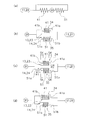
- the inertia member I and the damper plate portion D are elastically connected by a coil spring C as shown in the model diagram shown in FIG.
- both ends of the coil spring C are A pair of window walls W11, W12 facing in the circumferential direction in the window portion W1 of the inertia member I, and a pair of window walls W21, W22 facing in the circumferential direction in the window portion W2 of the damper plate portion D, It is in contact.
- the coil spring C is one of the window walls in the inertia member I. It is compressed by W11 and one window wall W22 in the damper plate portion D.
- a gap S is formed between one end of the coil spring C and the window wall W12 of the inertia member I. Further, a gap S is also formed between the other end of the coil spring C and the window wall W21 of the damper plate portion D.
- the coil spring C is the other member of the inertia member I. It is compressed by the window wall W12 and the other window wall W21 in the damper plate portion D.
- a gap S is formed between one end of the coil spring C and the window wall W11 of the inertia member I. Further, a gap S is also formed between the other end of the coil spring C and the window wall W22 of the damper plate portion D.
- the damper device that operates as described above passes through the neutral state in FIG. 7C when shifting from the first rotation state in FIG. 7B to the second rotation state in FIG. 7D.
- the gap S becomes zero, and the end portion of the coil spring C collides with the window wall W12 of the inertia member I and the window wall W21 of the damper plate portion D.
- the window wall that compresses the coil spring C is switched from the window walls W11 and W22 to the window walls W12 and W21.
- the present invention has been made in view of the above problems, and an object of the present invention is to provide a damper device that can be operated smoothly. Another object of the present invention is to provide a damper device capable of reducing operating noise. Still another object of the present invention is to provide a damper device capable of improving robustness against repeated stress acting on an elastic member.
- the damper device can attenuate torque fluctuations.
- the damper device includes a first rotating body, a second rotating body, and a plurality of elastic members.
- the second rotating body is configured to be rotatable relative to the first rotating body.
- the plurality of elastic members elastically connect the first rotating body and the second rotating body.
- the second rotating body is rotatable relative to the first rotating body in a state where the first rotating body holds the second rotating body using a plurality of elastic members.
- the elastic member only elastically connects the first rotating body and the second rotating body, and thus the above-described problem. Had occurred.
- the first rotating body holds the second rotating body using a plurality of elastic members (see FIG. 4A). For this reason, even if the rotation direction is reversed via the neutral state, switching of the portion that presses the elastic member does not occur. Further, when the first rotating body holds the second rotating body using a plurality of elastic members, the second rotating body rotates relative to the first rotating body, so that the torque fluctuation is attenuated. Is done.
- this damper device can operate smoothly compared to the conventional damper device. Moreover, in this damper apparatus, an operation sound can also be reduced compared with the conventional damper apparatus.
- the damper device can be configured by the configuration in which the first rotating body holds the second rotating body using a plurality of elastic members. It can be operated stably. That is, in this damper apparatus, the robustness with respect to the repetitive stress which acts on an elastic member can be improved.
- the plurality of elastic members operate in a compressed state between the first rotating body and the second rotating body.
- the 1st rotary body can hold
- the plurality of elastic members are the first rotating body and the second rotating body so that the total deformation amount in the plurality of elastic members is substantially zero.
- the plurality of elastic members elastically connect the first rotating body and the second rotating body, when a certain elastic member is compressed, the other elastic members are stretched, so that the plurality of elastic members are elastic.
- the total amount of deformation in the member is substantially zero.
- the 1st rotation body can hold the 2nd rotation body stably using a plurality of elastic members.
- each of the plurality of elastic members has the same rigidity. Therefore, the 1st rotation body can hold the 2nd rotation body stably using a plurality of elastic members.
- the plurality of elastic members include a first elastic member and a second elastic member.
- the first elastic member presses the second rotating body in the first rotating direction in a state where the first elastic member is in contact with the first rotating body.
- the second elastic member presses the second rotating body in the second rotation direction opposite to the first rotation direction in a state where the second elastic member is in contact with the first rotating body.
- the plurality of elastic members include a first elastic member and a second elastic member.
- first elastic member and the second elastic member When either one of the first elastic member and the second elastic member is compressed between the first rotating body and the second rotating body, one of the first elastic member and the second elastic member is the first It extends between the rotating body and the second rotating body.
- the 1st rotating body and the 2nd rotating body can operate stably, maintaining the balance of the 1st and 2nd elastic members.
- the plurality of elastic members include a first elastic member and a second elastic member.
- the first rotating body includes a first storage portion that stores the first elastic member, and a second storage portion that stores the second elastic member.
- the second rotating body is disposed to face the first housing portion and stores the first elastic member, and the fourth rotating body is disposed to face the second housing portion and houses the second elastic member.
- the first storage unit is offset in the first rotation direction with respect to the third storage unit.
- the second storage part is offset with respect to the fourth storage part in the second rotation direction opposite to the first rotation direction.
- the first rotating body and the second rotating body can be stably moved without switching the portions that press the first and second elastic members. Can be operated.
- the plurality of elastic members include a first elastic member and a second elastic member.
- the first elastic member contacts the first storage portion located inside the third storage portion and the third storage portion located inside the first storage portion when viewed in the axial direction.
- the second elastic member contacts the second storage portion located inside the fourth storage portion and the fourth storage portion located inside the second storage portion when viewed in the axial direction.
- the first rotating body and the second rotating body can be stably moved without switching the portions that press the first and second elastic members. Can be operated.
- the damper device can be operated smoothly. Moreover, in this invention, the operating sound of a damper apparatus can be reduced. Furthermore, in the present invention, it is possible to improve the robustness of the damper device against repeated stress acting on the elastic member.
- FIG. 1 is a cross-sectional view of a dynamic damper device according to a first embodiment of the present invention.
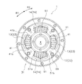
- the front view of a dynamic damper device in a 1st embodiment except for the 1st retaining plate).
- the dynamic damper device 1 As shown in FIG. 1, the dynamic damper device 1 according to the first embodiment of the present invention is attached to a drive shaft 100. Specifically, the dynamic damper device 1 is attached to the drive shaft 100 via the connecting member 101. The connecting member 101 is attached to the drive shaft 100 so as to be integrally rotatable, and transmits the torque (including torque fluctuation) of the drive shaft 100 to the dynamic damper device 1. The torque fluctuation transmitted here is attenuated by the dynamic damper device 1.
- the OO line is the rotation axis.
- the direction along the rotation axis O may be referred to as “axial direction”.
- a direction away from the rotation axis O may be referred to as a “radial direction”.
- the direction around the rotation axis O may be referred to as “circumferential direction” and / or “rotational direction”.
- the dynamic damper device 1 includes a first retaining plate 11, a second retaining plate 21, an inertia part 31, and a plurality of first and second coil springs 41 and 51. have.
- first retaining plate 11 and the second retaining plate 21 are examples of the first rotating body.
- the inertia part 31 is an example of a second rotating body.
- Each of the first and second coil springs 41 and 51 is an example of an elastic member.
- the first coil spring 41 is an example of a first elastic member
- the second coil spring 51 is an example of a second elastic member.
- the first retaining plate 11 and the second retaining plate 21 hold the inertia part 31 using a plurality of first and second coil springs 41 and 51.
- the first retaining plate 11 and the second retaining plate 21 are disposed on both sides of the inertia part 31 in the axial direction.
- the 1st retaining plate 11 and the 2nd retaining plate 21 are arrange
- the first retaining plate 11 and the second retaining plate 21 are fixed to the connecting member 101 by fixing means 29 such as a plurality of bolts and nuts.
- the first retaining plate 11 is a member disposed on the connecting member 101 side.
- the first retaining plate 11 is disposed between the second retaining plate 21 and the connecting member 101 in the axial direction.
- the first retaining plate 11 includes a first plate body 12, a plurality of (for example, two) first storage windows 13, and a plurality of (for example, two) second storage windows. 14.
- the first storage window 13 is an example of a first storage part
- the second storage window 14 is an example of a second storage part.
- the first plate body 12 is formed in a substantially annular shape.
- the plurality of first storage windows 13 and the plurality of second storage windows 14 are formed in the first plate body 12.
- the plurality of first storage windows 13 and the plurality of second storage windows 14 are arranged side by side in the circumferential direction.
- the 1st storage window 13 and the 2nd storage window 14 are arrange
- the plurality of first storage windows 13 and the plurality of second storage windows 14 are formed, for example, in a substantially rectangular shape.
- a first coil spring 41 is housed in each of the plurality of first housing windows 13 so as to be elastically deformable in the rotational direction.
- the second coil spring 51 is stored so as to be elastically deformable in the rotation direction.
- the second retaining plate 21 is arranged so as to have a mirror image relationship with the first retaining plate 11 with respect to a plane orthogonal to the rotation axis O. Except for this point, the second retaining plate 21 has substantially the same configuration as the first retaining plate 11. For this reason, the code
- the second retaining plate 21 includes a second plate body 22, a plurality of (for example, two) third storage windows 23, and a plurality of (for example, two) fourth storage windows. 24.
- the third storage window 23 is an example of a first storage unit
- the fourth storage window 24 is an example of a second storage unit.
- the second plate body 22 is substantially formed in an annular shape.
- the second plate body 22 is disposed to face the first plate body 12 in the axial direction.
- the second plate main body 22 is disposed to face the first plate main body 12 in the axial direction via the boss member 19 (see FIG. 1).
- the boss member 19 is disposed between the first plate main body 12 and the second plate main body 22, and holds the interval between the first plate main body 12 and the second plate main body 22 at a predetermined interval.
- the second plate body 22 is fixed to the connecting member 101 together with the first plate body 12 by fixing means 29 such as bolts and nuts. That is, the 1st plate main body 12 and the 2nd plate main body 22 are comprised so that integral rotation is possible with the drive shaft 100 (connection member 101).
- the shaft portion of the bolt 29 is inserted into the bolt hole of the first plate body 12, the inner peripheral portion of the boss member 19, and the bolt hole of the second plate body 22. Then, the first plate main body 12, the boss member 19, and the second plate main body 22 are fixed to the connecting member 101 by the fixing means 29 (bolt head and nut).
- the boss member 19 constitutes a stopper mechanism described later.
- the plurality of third storage windows 23 and the plurality of fourth storage windows 24 are formed in the second plate body 22.
- the plurality of third storage windows 23 and the plurality of fourth storage windows 24 are arranged side by side in the circumferential direction.
- the 3rd storage window 23 and the 4th storage window 24 are arrange
- the third storage window 23 is disposed to face the first storage window 13 in the axial direction. Further, the fourth storage window 24 is disposed to face the second storage window 14 in the axial direction.
- the first storage window 13 and the third storage window 23 form a set of storage windows in the axial direction.
- the second storage window 14 and the fourth storage window 24 form a set of storage windows in the axial direction.
- the plurality of third storage windows 23 and the plurality of fourth storage windows 24 are formed in a substantially rectangular shape, for example.
- the first coil spring 41 is stored so as to be elastically deformable in the rotation direction.
- the second coil spring 51 is stored so as to be elastically deformable in the rotation direction.
- the inertia part 31 is configured to be rotatable with respect to the first retaining plate 11 and the second retaining plate 21. Specifically, the inertia part 31 is in a state where the first retaining plate 11 and the second retaining plate 21 hold the inertia part 31 in the rotational direction by using the plurality of first and second coil springs 41 and 51. Is configured to be relatively rotatable with respect to the first retaining plate 11 and the second retaining plate 21.
- the inertia part 31 is disposed between the first retaining plate 11 and the second retaining plate 21 in the axial direction.
- the inertia part 31 includes an inertia ring 32, an additional mass part 33, a plurality of (for example, two) fifth storage windows 34, a plurality of (for example, two) sixth storage windows 35, and a plurality (for example, four). Individual) restricting window 36.
- the fifth storage window 34 is an example of a third storage part
- the sixth storage window 35 is an example of a fourth storage part.
- the inertia ring 32 is formed in a substantially annular shape.
- the inertia ring 32 is disposed between the first plate body 12 and the second plate body 22 in the axial direction.
- the inertia ring 32 is configured to be rotatable relative to the first plate body 12 and the second plate body 22. Specifically, the inertia ring 32 is held by the first plate body 12 and the second plate body 22 via a plurality of first and second coil springs 41 and 51.
- the additional mass portion 33 is attached to the outer peripheral portion of the inertia ring 32.
- the additional mass unit 33 includes a pair of plate members 33a and a fixing member 33b.
- the pair of plate members 33a is disposed on both sides of the inertia ring 32 in the axial direction, and is fixed to the inertia ring 32 by a fixing member 33b.
- the fixing member 33b is, for example, a bolt and a nut.
- the plurality of fifth storage windows 34 and the plurality of sixth storage windows 35 are formed in the inertia ring 32.
- the plurality of fifth storage windows 34 and the plurality of sixth storage windows 35 are arranged side by side in the circumferential direction.
- the fifth storage window 34 and the sixth storage window 35 are disposed adjacent to each other in the circumferential direction.
- the fifth storage window 34 is disposed between the first storage window 13 and the third storage window 23 so as to face the first storage window 13 and the third storage window 23 in the axial direction.
- the sixth storage window 35 is disposed opposite to the second storage window 14 and the fourth storage window 24 between the second storage window 14 and the fourth storage window 24 in the axial direction.
- the fifth storage window 34 is provided in the inertia ring 32 so as to be offset in the first rotation direction R ⁇ b> 1 with respect to the first storage window 13 and the third storage window 23.
- the sixth storage window 35 is provided on the inertia ring 32 so as to be offset with respect to the second storage window 14 and the fourth storage window 24 in the second rotation direction R2 opposite to the first rotation direction R1. Yes.
- the first storage window 13, the third storage window 23, and the fifth storage window 34 are arranged at 9 o'clock and 3 o'clock positions.
- the second storage window 14, the fourth storage window 24, and the sixth storage window 35 are disposed at the 6 o'clock and 12 o'clock positions.
- the fifth storage window 34 is provided at a position offset from the first storage window 13 and the third storage window 23 by a predetermined rotation angle in the first rotation direction R1.
- the sixth storage window 35 is provided at a position that is offset from the second storage window 14 and the fourth storage window 24 by a predetermined rotation angle in the second rotation direction R2.
- FIG. 3 is a diagram showing a state where the relative rotation between the first retaining plate 11 and the second retaining plate 21 and the inertia part 31 is substantially “zero (0)”, that is, a neutral state. is there.
- the plurality of fifth storage windows 34 and the plurality of sixth storage windows 35 are, for example, substantially rectangular.
- the first coil spring 41 is stored so as to be elastically deformable in the rotation direction.
- the second coil spring 51 is stored so as to be elastically deformable in the rotation direction.
- each of the plurality of restriction windows 36 is formed in the inertia ring 32.
- Each of the plurality of restriction windows 36 is arranged side by side in the circumferential direction.
- the restriction window 36 is disposed between the first storage window 13 and the second storage window 14 (the third storage window 23 and the fourth storage window 24) that are adjacent in the circumferential direction.
- Each of the plurality of restriction windows 36 is formed in a substantially rectangular shape, for example.
- a boss member 19 is disposed in each of the plurality of restriction windows 36.
- the boss member 19 is movable in the circumferential direction inside the restriction window 36.
- the boss member 19 can be brought into contact with one of a pair of wall portions facing each other in the circumferential direction in the restriction window 36.
- a shaft portion of a bolt 29 for fixing the first retaining plate 11 and the second retaining plate 21 to the connecting member 101 is disposed on the inner peripheral portion of the boss member 19. That is, the shaft portion of the bolt 29 is inserted into each of the plurality of restriction windows 36, and the boss member 19 is disposed on the outer peripheral portion of the shaft portion of the bolt 29.
- the boss member 19 moves inside the regulating window 36 together with the shaft portion of the bolt 29.
- the boss member 19 comes into contact with the wall portion of the restriction window 36.
- the boss member 19 and the restriction window 36 function as a stopper mechanism for the inertia part 31 with respect to the first retaining plate 11 and the second retaining plate 21.
- restriction windows 36 may be set in any way as long as at least one restriction window 36 is provided.
- the plurality of (for example, two) first coil springs 41 and the plurality of (for example, two) second coil springs 51 include a first retaining plate 11 and a second retaining plate.
- the plate 21 and the inertia part 31 are elastically connected in the rotation direction.
- the first coil spring 41 and the second coil spring 51 operate as a set of coil springs.
- two sets of coil spring groups two sets of first coil spring 41 and second coil spring 51 are used.
- the first retaining plate 11 and the second retaining plate 21 hold the inertia part 31 in the rotational direction.
- first coil spring 41 and the second coil spring 51 have the same rigidity.
- the natural lengths of the first coil spring 41 and the second coil spring 51 are the same.
- the first coil spring 41 is arranged in a compressed state (less than natural length) in the first storage window 13 and the third storage window 23 and the offset fifth storage window 34.
- the second coil spring 51 is disposed in the second storage window 14 and the fourth storage window 24 and the offset sixth storage window 35 in a compressed state (less than natural length).
- one end 41 a of the first coil spring 41 abuts against the wall of the first storage window 13 and the wall of the third storage window 23 (see FIG. 2), and the other end 41 b of the first coil spring 41. Is in contact with the offset wall portion of the fifth storage window 34 (see FIG. 3).
- One end 51a (see FIG. 2) of the second coil spring 51 abuts against the wall of the second storage window 14 and the wall of the fourth storage window 24, and the other end 51b (see FIG. 2) of the second coil spring 51. 3) is in contact with the offset wall portion of the sixth storage window 35.
- the one end 41a of the first coil spring 41 is an end on the downstream side in the first rotation direction R1.
- the other end 41b of the first coil spring 41 is an upstream end in the first rotation direction R1.
- the one end 51a of the second coil spring 51 is the downstream end in the second rotational direction R2.
- the other end 51b of the second coil spring 51 is an upstream end in the second rotational direction R2.
- the wall portions of the first to sixth storage windows 13, 14, 23, 24, 34, and 35 are either one of a pair of wall portions facing each other in the circumferential direction.
- the one end 41 a of the first coil spring 41 is located inside the fifth storage window 34. It abuts against the wall portion of the first storage window 13 and the wall portion of the third storage window 23 that are positioned.
- the other end 41 b of the first coil spring 41 abuts against the wall portion of the fifth storage window 34 that is located inside the first storage window 13 and inside the third storage window 23.
- the one end portion 51 a of the second coil spring 51 abuts against the wall portion of the first storage window 13 and the wall portion of the third storage window 23 located inside the sixth storage window 35.
- the other end 51 b of the second coil spring 51 abuts against the wall portion of the sixth storage window 35 located inside the first storage window 13 and inside the third storage window 23.
- the first coil spring 41 is in contact with the first retaining plate 11 and the second retaining plate 21, and the inertia portion 31 is moved. Press in the second rotation direction R2.
- the second coil spring 51 presses the inertia part 31 in the first rotation direction R ⁇ b> 1 in a state where the second coil spring 51 is in contact with the first retaining plate 11 and the second retaining plate 21.
- first and second coil springs 41 and 51 hold the inertia part 31 in the rotation direction. That is, the first retaining plate 11 and the second retaining plate 21 use the first coil spring 41 and the second coil spring 51 to hold the inertia part 31 in the rotational direction.
- the first coil spring 41 is compressed between the first retaining plate 11 and the second retaining plate 21 and the inertia part 31.
- the second coil spring 51 extends.
- the first coil spring 41 and the second coil spring 51 are compressed, the second coil spring 51 is interposed between the first retaining plate 11 and the second retaining plate 21 and the inertia part 31. When compressed, the first coil spring 41 extends.
- each of the first coil spring 41 and the second coil spring 51 expands and contracts in a compressed state.
- the first coil spring 41 and the second coil spring 51 are set so that the total deformation amount in the plurality of first coil springs 41 and the plurality of second coil springs 51 is substantially zero (0).
- the wall portion of the first storage window 13 and the wall portion of the third storage window 23 with which the one end portion 41 a of the first coil spring 41 abuts move in the circumferential direction inside the fifth storage window 34.
- the wall portion of the fifth storage window 34 with which the other end portion 41 b of the first coil spring 41 abuts moves in the circumferential direction inside the first storage window 13 and inside the third storage window 23.
- the wall portion of the second storage window 14 and the wall portion of the fourth storage window 24 with which the one end portion 51 a of the second coil spring 51 abuts are arranged in the circumferential direction inside the sixth storage window 35.
- the wall portion of the sixth storage window 35 with which the other end portion 51 b of the second coil spring 51 abuts moves in the circumferential direction inside the second storage window 14 and inside the fourth storage window 24.
- the wall portion of the first storage window 13 and the wall portion of the third storage window 23 are used.
- the interval SK between the fifth storage window 34 and the wall portion is configured to be larger than zero (0).
- the distance SK between the wall portion of the second storage window 14 and the wall portion of the fourth storage window 24 and the wall portion of the sixth storage window 35 is larger than zero (0). It is comprised so that it may become.
- the distance SK between the wall portion of the first and third storage windows 13 and 23 and the wall portion of the fifth storage window 34 and the walls of the second and fourth storage windows 14 and 24 was shown. However, if the distance between the two is greater than zero (0), the dynamic damper device may be configured so that the distance between the two is different.
- the first retaining plate 11 and the second retaining plate 21 rotate in the first rotation direction R1 or the second rotation direction R2 due to torque fluctuation. Then, due to this torque fluctuation, the inertia part 31 passes through the plurality of coil springs (the plurality of first coil springs 41 and the plurality of second coil springs 51) to the first retaining plate 11 and the second retaining plate 21. Rotates relative to.
- the inertia part 31 is opposite to the rotation direction (first rotation direction R1 or second rotation direction R2) of the first retaining plate 11 and the second retaining plate 21 via a plurality of coil springs (first rotation direction R1 or second rotation direction R2). 2 rotation direction R2 or 1st rotation direction R1).
- the torque fluctuation is attenuated by the relative rotation of the inertia part 31.
- the stopper mechanism (the wall portion of the boss member 19 and the restriction window 36).
- the rotation of the inertia part 31 is regulated.
- the first coil spring 41 is between the wall portions of the first and third storage windows 13 and 23 and the offset wall portion of the fifth storage window 34. It expands and contracts in a compressed state.
- the second coil spring 51 expands and contracts in a compressed state between the wall portions of the second and fourth storage windows 14 and 24 and the wall portion of the offset sixth storage window 35.
- the first and second coil springs 41 and 51 expand and contract in the compressed state within a range less than the offset amount in the neutral state.
- the inertia part 31 rotates relatively with respect to the 1st and 2nd retaining plates 11 and 21 within the range of less than offset amount (less than SK).
- the first and second retaining plates 11 and 21 use the plurality of first and second coil springs 41 and 51 to hold the inertia part 31 in the rotational direction.
- the first and second retaining plates 11 and 21 can be rotated relative to each other.
- the dynamic damper device 1 can attenuate torque fluctuations.
- the dynamic damper device 1 includes a first retaining plate 11 and a second retaining plate 21, an inertia part 31, and a plurality of first and second coil springs 41 and 51.
- the inertia part 31 is configured to be rotatable relative to the first retaining plate 11 and the second retaining plate 21.
- the plurality of first and second coil springs 41 and 51 elastically connect the first retaining plate 11 and the second retaining plate 21 to the inertia part 31.
- the inertia part 31 is in a state where the first retaining plate 11 and the second retaining plate 21 hold the inertia part 31 using the plurality of first and second coil springs 41 and 51. However, it can rotate relative to the first retaining plate 11 and the second retaining plate 21. As a result, torque fluctuations are attenuated. Moreover, even if the rotation direction is reversed via the neutral state, switching of the portion that presses the first and second coil springs 41 and 51 does not occur.
- the dynamic damper device 1 can operate smoothly as compared with the conventional damper device.
- the dynamic damper device 1 can also reduce the operation noise as compared with the conventional damper device.
- the dynamic damper device 1 there is a possibility that the plurality of first and second coil springs 41, 51 may sag due to repeated stress acting on the plurality of first and second coil springs 41, 51. . That is, the free lengths of the plurality of first and second coil springs 41 and 51 may change. Thereby, even if the free length of each of the plurality of first and second coil springs 41 and 51 varies, the first retaining plate 11 and the first retaining plate 11 and the second coil springs 41 and 51 are used.
- the dynamic damper device 1 can be stably operated by the configuration in which the two retaining plates 21 hold the inertia part 31.
- the first and second coil springs 41 and 51 always hold the inertia part 31 by the force that the first and second coil springs 41 and 51 extend. Therefore, even if the above-described variation occurs, the dynamic damper The apparatus 1 can be operated stably. That is, in the dynamic damper device 1, robustness against repeated stress acting on the first and second coil springs 41 and 51 can be improved.
- the present invention has been described by using the dynamic damper device 1 as an example of a damper device.
- the present invention is applicable not only to the dynamic damper device 1 but also to the clutch device. For this reason, in 2nd Embodiment, description of this invention is performed using a clutch apparatus.
- third and fourth coil springs 94 and 95 (described later) in the second embodiment is substantially the same as the configuration of first and second coil springs 41 and 51 in the first embodiment.
- the seventh to twelfth storage windows 92a, 92b, 93a, 93b, 83c, and 83d (described later) of the second embodiment are configured in the first to sixth storage windows 13, 14, and 23 of the first embodiment. 24, 34, and 35 are substantially the same.
- the description of the third and fourth coil springs 94 and 95 and the description of the seventh to twelfth storage windows may be omitted.
- omitted it applies to description of 1st Embodiment.
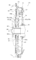
- the clutch device 61 (Configuration of clutch device) is disposed between an engine (not shown) and a transmission (not shown). As shown in FIG. 5, the OO line is the rotation axis. The engine is arranged on the left side of FIG. 5, and the transmission is arranged on the right side of FIG.
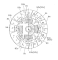
- the clutch device 61 is for transmitting and interrupting torque from the engine to the transmission. As shown in FIGS. 5 and 6, the clutch device 61 includes a clutch cover assembly 71 and a clutch disk assembly 81.
- the clutch disk assembly 81 is an example of a damper device.
- the clutch cover assembly 71 has a clutch cover 72, a pressure plate 73, and a diaphragm spring 74.
- the clutch cover 72 is an annular member fixed to the flywheel 90. Inside the clutch cover 72, a pressure plate 73, a diaphragm spring 74, and a clutch disc assembly 81 are accommodated.
- the pressure plate 73 is a member that holds the clutch disk 84 between the flywheel 90 and the pressure plate 73.
- the pressure plate 73 is formed in a substantially annular shape.
- the pressure plate 73 is provided so as to be non-rotatable and movable in the axial direction with respect to the clutch cover 72.
- the diaphragm spring 74 is a member that biases the pressure plate 73 toward the flywheel 90.
- the diaphragm spring 74 is provided so as not to rotate with respect to the clutch cover 72.
- the diaphragm spring 74 is provided so as to be elastically deformable in the axial direction with respect to the clutch cover 72. For example, when the diaphragm spring 74 is pressed in the axial direction by the release device 91, the diaphragm spring 74 is elastically deformed in the axial direction and biases the pressure plate 73 toward the flywheel 90.
- the clutch disk assembly 81 can attenuate torque fluctuations.
- the clutch disk assembly 81 has a damper mechanism 82, a spline hub 83, and a clutch disk 84.
- the spline hub 83 is an example of a first rotating body.
- the damper mechanism 82 elastically connects the clutch disk 84 and the spline hub 83.
- the damper mechanism 82 includes a clutch plate 92, a retaining plate 93, and a plurality of third and fourth coil springs 94 and 95.
- the clutch plate 92 and the retaining plate 93 are examples of the second rotating body.
- Each of the third and fourth coil springs 94 and 95 is an example of an elastic member.
- the third coil spring 94 is an example of a first elastic member
- the fourth coil spring 95 is an example of a second elastic member.
- the clutch plate 92 and the retaining plate 93 are arranged on both sides of a flange portion 83b (described later) of the spline hub 83 in the axial direction.
- the clutch plate 92 and the retaining plate 93 are connected to each other in the axial direction by fixing means such as a plurality of rivets.
- the clutch plate 92 and the retaining plate 93 are formed in a substantially annular shape.
- the clutch plate 92 has a plurality of (for example, two) seventh storage windows 92a and a plurality of (for example, two) eighth storage windows 92b.
- the plurality of seventh storage windows 92 a and the plurality of eighth storage windows 92 b are formed in the clutch plate 92.
- the multiple seventh storage windows 92a and the multiple eighth storage windows 92b are arranged side by side in the circumferential direction.
- the seventh storage window 92a and the eighth storage window 92b are disposed adjacent to each other in the circumferential direction.
- the plurality of seventh storage windows 92a and the plurality of eighth storage windows 92b are formed, for example, in a substantially rectangular shape.
- the third coil spring 94 is stored so as to be elastically deformable in the rotation direction.
- a fourth coil spring 95 is stored so as to be elastically deformable in the rotation direction.
- the clutch plate 92 is arranged so as to have a mirror image relationship with the retaining plate 93 with respect to a plane orthogonal to the rotation axis O. For this reason, the code
- the seventh storage window 92a is an example of a first storage unit, and corresponds to the first storage window 13 of the first embodiment.
- the eighth storage window 92b is an example of a second storage portion, and corresponds to the second storage window 14 of the first embodiment.
- the retaining plate 93 has a plurality (for example, two) of ninth storage windows 93a and a plurality (for example, two) of tenth storage windows 93b.
- the plurality of ninth storage windows 93 a and the plurality of tenth storage windows 93 b are formed on the retaining plate 93.
- the plurality of ninth storage windows 93a and the plurality of tenth storage windows 93b are arranged side by side in the circumferential direction.
- the ninth storage window 93a and the tenth storage window 93b are arranged adjacent to each other in the circumferential direction.
- the ninth storage window 93a is disposed to face the seventh storage window 92a in the axial direction. Further, the tenth storage window 93b is disposed to face the eighth storage window 92b in the axial direction.
- the seventh storage window 92a and the ninth storage window 93a form a set of storage windows in the axial direction. Further, the eighth storage window 92b and the tenth storage window 93b form a set of storage windows in the axial direction.
- the plurality of ninth storage windows 93a and the plurality of tenth storage windows 93b are formed in a substantially rectangular shape, for example.
- the third coil spring 94 is stored so as to be elastically deformable in the rotation direction.
- a fourth coil spring 94 is stored so as to be elastically deformable in the rotation direction.
- the ninth storage window 93a is an example of a first storage unit, and corresponds to the third storage window 23 of the first embodiment.
- the 10th storage window 93b is an example of a 2nd storage part, and respond
- the spline hub 83 is disposed on the outer peripheral side of the input shaft 98 of the transmission.
- the spline hub 83 includes a hub 83a, a flange portion 83b, a plurality (for example, two) of eleventh storage windows 83c, and a plurality (for example, two) of twelfth storage windows 83d.
- the hub 83a is a cylindrical member extending in the axial direction.
- the hub 83a is spline-engaged with the input shaft 98.
- the flange portion 83b is a portion that extends radially outward from the outer peripheral portion of the hub 83a.
- the flange portion 83b is formed substantially in an annular shape.
- the plurality of eleventh storage windows 83c and the plurality of twelfth storage windows 83d are formed in the flange portion 83b.
- the plurality of eleventh storage windows 83c and the plurality of twelfth storage windows 83d are arranged side by side in the circumferential direction.
- the plurality of eleventh storage windows 83c and the plurality of twelfth storage windows 83d are arranged adjacent to each other in the circumferential direction.
- the eleventh storage window 83c is disposed between the seventh storage window 92a and the ninth storage window 93a in the axial direction so as to face the seventh storage window 92a and the ninth storage window 93a.
- the twelfth storage window 83d is disposed between the eighth storage window 92b and the tenth storage window 93b so as to face the eighth storage window 92b and the tenth storage window 93b in the axial direction.
- the eleventh storage window 83c is offset from the seventh storage window 92a and the ninth storage window 93a in the first rotation direction R1.
- the twelfth storage window 83d is disposed with an offset in the second rotation direction R2 opposite to the first rotation direction R1 with respect to the eighth storage window 92b and the tenth storage window 93b.
- the eleventh storage window 83c is an example of a third storage unit, and corresponds to the fifth storage window 34 of the first embodiment.
- the twelfth storage window 83d is an example of a fourth storage portion, and corresponds to the sixth storage window 35 of the first embodiment.
- the relationship between the eleventh storage window 83c and the seventh and ninth storage windows 92a and 93a is the same as that of the fifth storage window 34 of the first embodiment and the first and second storage windows of the first embodiment.
- the relationship with the third storage windows 13 and 23 is substantially the same.
- the relationship between the twelfth storage window 83d and the eighth and tenth storage windows 92b and 93b is the same as the sixth storage window 35 of the first embodiment and the second and second of the first embodiment.
- the relationship with the four storage windows 14 and 24 is substantially the same. For this reason, the description about the offset is omitted here and is equivalent to the description of the first embodiment.
- the plurality of eleventh storage windows 83c and the plurality of twelfth storage windows 83d are formed, for example, in a substantially rectangular shape.
- a third coil spring 94 is housed in each of the plurality of eleventh storage windows 83c.
- a fourth coil spring 95 is stored in each of the plurality of twelfth storage windows 83d.
- a plurality (for example, two) of third coil springs 94 and a plurality of (for example, two) fourth coil springs 95 connect the clutch plate 92, the retaining plate 93, and the spline hub 83 in the rotational direction. .
- the third coil spring 94 and the fourth coil spring 95 operate as a set of coil spring groups.
- two sets of coil spring groups are used. With these two sets of coil spring groups, the spline hub 83 (flange portion 83b) holds the clutch plate 92 and the retaining plate 93 in the rotational direction.
- each of the third coil spring 94 and the fourth coil spring 95 is the same.
- the natural lengths of the third coil spring 94 and the fourth coil spring 95 are the same.
- the third coil spring 94 is disposed in a compressed state (less than natural length) in the seventh storage window 92a and the ninth storage window 93a and the offset eleventh storage window 83c.
- the fourth coil spring 95 is disposed in the compressed state (less than natural length) in the eighth storage window 92b and the tenth storage window 93b and the offset twelfth storage window 83d.
- the third coil spring 94 corresponds to the first coil spring 41 of the first embodiment.
- the fourth coil spring 95 corresponds to the second coil spring 51 of the first embodiment.
- the relationship between the third and fourth coil springs 94, 95 and the seventh to twelfth receiving windows 92a, 92b, 93a, 93b, 83c, 83d is the same as that of the first and second coil springs of the first embodiment. 41 and 51 and the relationship between the first to sixth storage windows 13, 14, 23, 24, 34, and 35 are substantially the same.
- the clutch disc 84 is for transmitting torque from the flywheel 90 to the clutch disc assembly 81.
- the clutch disc 84 is connected to the damper mechanism 82.
- the clutch disk 84 has a pair of friction facings 84a and a cushioning plate 84b.
- the friction facing 84 a is a portion that is sandwiched between the flywheel 90 and the pressure plate 73 and frictionally engages with the flywheel 90 and the pressure plate 73.
- the friction facing 84a is made of a friction material.
- the friction facings 84a are mounted on both sides of the cushioning plate 84b in the axial direction.
- the cushioning plate 84b elastically supports the pair of friction facings 84a in the axial direction.
- the cushioning plate 84b is non-rotatably connected to the damper mechanism 82.
- the cushioning plate 84b is fixed to the outer peripheral portion of the clutch plate 92 by fixing means such as a plurality of rivets.
- the third coil spring 94 is compressed between the wall portions of the seventh and ninth storage windows 92a and 93a and the wall portion of the offset eleventh storage window 83c. It expands and contracts.
- the fourth coil spring 95 extends and contracts in a compressed state between the wall portions of the eighth and tenth storage windows 92b and 93b and the offset wall portion of the twelfth storage window 83d.
- the third and fourth coil springs 94 and 95 expand and contract in the compressed state within a range less than the offset amount in the neutral state (less than SK in FIG. 4). Further, the clutch plate 92 and the retaining plate 93 rotate relative to the spline hub 83 within a range less than the offset amount (less than SK in FIG. 4).
- the spline hub 83 holds the clutch plate 92 and the retaining plate 93 in a state where the clutch plate 92 and the retaining plate 93 are held in the rotational direction by using the plurality of third and fourth coil springs 94 and 95.
- the spline hub 83 can be rotated relative to the spline hub 83.
- the clutch disk assembly 81 can attenuate torque fluctuations.
- the clutch disk assembly 81 includes a spline hub 83, a clutch plate 92 and a retaining plate 93, and a plurality of third and fourth coil springs 94 and 95.
- the clutch plate 92 and the retaining plate 93 are configured to be rotatable relative to the spline hub 83.
- the plurality of third and fourth coil springs 94 and 95 elastically connect the clutch plate 92 and the retaining plate 93 to the spline hub 83.
- the spline hub 83 holds the clutch plate 92 and the retaining plate 93 in the rotational direction by using a plurality of third and fourth coil springs 94 and 95. In this state, the spline hub 83 rotates the clutch plate 92 and the retaining plate 93 relative to the spline hub 83. As a result, torque fluctuations are attenuated. Further, even if the rotation direction is reversed via the neutral state, switching of the portion that presses the third and fourth coil springs 94 and 95 does not occur.
- the clutch disk assembly 81 can operate smoothly as compared with the conventional damper device.
- the clutch disk assembly 81 can reduce the operating noise as compared with the conventional damper device.
- the spline hub 83 can be connected to the clutch plate 92 and the clutch plate 92 using the plurality of third and fourth coil springs 94 and 95.
- the clutch disk assembly 81 can be stably operated by the structure that holds the retaining plate 93.
- the third and fourth coil springs 94 and 95 always hold the clutch plate 92 and the retaining plate 93 by the extending force of the third and fourth coil springs 94 and 95, so that the above-described variation occurs. Even in this case, the clutch disk assembly 81 can be stably operated. In other words, in the present clutch disk assembly 81, robustness against repeated stress acting on the third and fourth coil springs 94 and 95 can be improved.
Landscapes
- Engineering & Computer Science (AREA)
- General Engineering & Computer Science (AREA)
- Mechanical Engineering (AREA)
- Physics & Mathematics (AREA)
- Acoustics & Sound (AREA)
- Aviation & Aerospace Engineering (AREA)
- Mechanical Operated Clutches (AREA)
Abstract
スムーズに作動させることができるダンパ装置を、提供することにある。本ダイナミックダンパ装置(1)は、第1リティーニングプレート(11)及び第2リティーニングプレート(21)と、イナーシャ部(31)と、複数の第1及び第2コイルスプリング(41,51)とを、備えている。イナーシャ部(31)は、第1リティーニングプレート(11)及び第2リティーニングプレート(21)に対して相対的に回転可能に構成される。複数の第1及び第2コイルスプリング(41,51)は、第1リティーニングプレート(11)及び第2リティーニングプレート(21)と、イナーシャ部(31)とを、弾性的に連結する。
Description
本発明は、ダンパ装置、特に、トルクの変動を減衰可能なダンパ装置に関する。
従来のダイナミックダンパ装置は、ダンパプレート部(45)と、イナーシャ部材(46)と、コイルスプリング(48a)とを、備えている(特許文献1を参照)。イナーシャ部材は、ダンパプレート部と相対回転可能である。コイルスプリングは、ダンパプレート部とイナーシャ部材とを、回転方向に弾性的に連結する。例えば、コイルスプリングは、イナーシャ部材の窓部(46a)及びダンパプレート部の窓部(45a)に配置されている。この状態で、イナーシャ部材がダンパプレート部に対して相対回転すると、コイルスこれにより、第1回転体及び第2回転体が作動する範囲において、ダンパ装置をスムーズに動作させることができる。
従来のダイナミックダンパ装置では、図7(a)に示すモデル図に示すように、イナーシャ部材I及びダンパプレート部Dが、コイルスプリングCによって、弾性的に連結されている。
このタイプのダイナミックダンパ装置では、図7(c)に示すように、イナーシャ部材I及びダンパプレート部Dの相対回転角がゼロである場合(中立状態の場合)、コイルスプリングCの両端部は、イナーシャ部材Iの窓部W1において円周方向に対向する1対の窓壁W11,W12と、ダンパプレート部Dの窓部W2において円周方向に対向する1対の窓壁W21,W22とに、当接している。
図7(b)に示すように、イナーシャ部材Iが、ダンパプレート部Dに対して、第1回転方向R1に回転した第1回転状態では、コイルスプリングCは、イナーシャ部材Iにおける一方の窓壁W11と、ダンパプレート部Dにおける一方の窓壁W22とによって、圧縮される。
この場合、コイルスプリングCの一端部と、イナーシャ部材Iの窓壁W12との間には、隙間Sが形成される。また、コイルスプリングCの他端部と、ダンパプレート部Dの窓壁W21との間にも、隙間Sが形成される。
また、図7(d)に示すように、イナーシャ部材Iが、ダンパプレート部Dに対して、第2回転方向R2に回転した第2回転状態では、コイルスプリングCは、イナーシャ部材Iにおける他方の窓壁W12と、ダンパプレート部Dにおける他方の窓壁W21とによって、圧縮される。
この場合、コイルスプリングCの一端部と、イナーシャ部材Iの窓壁W11との間には、隙間Sが形成される。また、コイルスプリングCの他端部と、ダンパプレート部Dの窓壁W22との間にも、隙間Sが形成される。
上記のように作動するダンパ装置は、図7(b)の第1回転状態から図7(d)の第2回転状態に移行する場合に、図7(c)の中立状態を経由する。中立状態では、上記の隙間Sがゼロになり、コイルスプリングCの端部と、イナーシャ部材Iの窓壁W12及びダンパプレート部Dの窓壁W21とが、衝突する。この衝突によって、コイルスプリングCを圧縮する窓壁が、窓壁W11,W22から窓壁W12,W21へと、切り換えられる。
なお、図7(d)の第2回転状態から図7(b)の第1回転状態に移行する場合にも、図7(c)の中立状態を移行する。この場合は、コイルスプリングCを圧縮する窓壁が、窓壁W12,W21から窓壁W11,W22へと、切り換えられる。
このように、回転方向が反転する場合、中立状態において、コイルスプリングCを押圧する部分(窓壁)が切り換えられる。この際には、上述したように、コイルスプリングCの端部及び窓壁が衝突するため、ダンパ装置のスムーズな動作が妨げられるおそれがある。また、この衝突によって、作動音が発生するおそれもある。
本発明は、上記の問題に鑑みてなされたものであって、本発明の目的は、スムーズに作動させることができるダンパ装置を、提供することにある。また、本発明の別の目的は、作動音を低減可能なダンパ装置を、提供することにある。さらに、本発明のさらに別の目的は、弾性部材に作用する繰り返し応力に対するロバスト性を向上可能なダンパ装置を、提供することにある。
(1)本発明の一側面に係るダンパ装置は、トルクの変動を減衰可能である。本ダンパ装置は、第1回転体と、第2回転体と、複数の弾性部材とを、備えている。第2回転体は、第1回転体に対して相対的に回転可能に構成される。複数の弾性部材は、第1回転体及び第2回転体を弾性的に連結する。このダンパ装置では、第1回転体が、複数の弾性部材を用いて、第2回転体を保持した状態で、第2回転体は、第1回転体に対して相対的に回転可能である。
ここで、図7(a)に示すように、従来技術の構成では、弾性部材が、第1回転体及び第2回転体を弾性的に連結しているだけであるため、上記のような問題が発生していた。これに対して、本ダンパ装置では、第1回転体が、複数の弾性部材を用いて、第2回転体を保持している(図4(a)を参照)。このため、回転方向が中立状態を経由して反転したとしても、弾性部材を押圧する部分の切り換えが、発生しない。また、第1回転体が複数の弾性部材を用いて第2回転体を保持した状態で、第2回転体が、第1回転体に対して相対的に回転することによって、トルクの変動が減衰される。
このように、本ダンパ装置は、従来のダンパ装置と比較して、スムーズに作動することができる。また、本ダンパ装置では、従来のダンパ装置と比較して、作動音を低減することもできる。
さらに、本ダンパ装置では、弾性部材に作用する繰り返し応力によって、弾性部材にへたり等が生じるおそれがある。これにより、弾性部材の自由長が変化し、弾性部材の自由長にバラツキが生じたとしても、複数の弾性部材を用いて第1回転体が第2回転体を保持する構成によって、ダンパ装置を安定的に作動させることができる。すなわち、本ダンパ装置では、弾性部材に作用する繰り返し応力に対するロバスト性を向上することができる。
(2)本発明の別の側面に係るダンパ装置では、複数の弾性部材は、第1回転体及び第2回転体の間において圧縮状態で作動する。これにより、複数の弾性部材の伸張力によって、第1回転体が第2回転体を確実に保持することができる。
(3)本発明の別の側面に係るダンパ装置では、複数の弾性部材における変形量の合計が、実質的にゼロになるように、複数の弾性部材は、第1回転体及び第2回転体を弾性的に連結する。この場合、例えば、複数の弾性部材が、第1回転体及び第2回転体を弾性的に連結した状態において、ある弾性部材が圧縮されると、他の弾性部材が伸びることによって、複数の弾性部材における変形量の合計が、実質的にゼロになる。これにより、第1回転体は、複数の弾性部材を用いて、安定的に第2回転体を保持することができる。
(4)本発明の別の側面に係るダンパ装置では、複数の弾性部材それぞれの剛性は、同じである。これにより、第1回転体は、複数の弾性部材を用いて、安定的に第2回転体を保持することができる。
(5)本発明の別の側面に係るダンパ装置では、複数の弾性部材は、第1弾性部材と、第2弾性部材とを、含む。第1弾性部材は、第1回転体に当接した状態で、第2回転体を、第1回転方向に押圧する。第2弾性部材は、第1回転体に当接した状態で、第2回転体を、第1回転方向とは反対の第2回転方向に、押圧する。これにより、第1回転体及び第2回転体は、第1及び第2弾性部材の釣り合いを保ちながら、安定的に作動することができる。
(6)本発明の別の側面に係るダンパ装置では、複数の弾性部材が、第1弾性部材と、第2弾性部材とを、含む。第1弾性部材及び第2弾性部材のいずれか一方が、第1回転体及び第2回転体の間で圧縮される場合は、第1弾性部材及び第2弾性部材のいずれか他方が、第1回転体及び第2回転体の間で伸張する。これにより、第1回転体及び第2回転体は、第1及び第2弾性部材の釣り合いを保ちながら、安定的に作動することができる。
(7)本発明の別の側面に係るダンパ装置では、複数の弾性部材が、第1弾性部材と、第2弾性部材とを、含む。第1回転体は、第1弾性部材を収納する第1収納部と、第2弾性部材を収納する第2収納部とを、含む。第2回転体は、第1収納部に対向して配置され且つ第1弾性部材を収納する第3収納部と、第2収納部に対向して配置され且つ第2弾性部材を収納する第4収納部とを、含む。第1収納部は、第3収納部に対して、第1回転方向にオフセットしている。第2収納部は、第4収納部に対して、第1回転方向とは反対の第2回転方向に、オフセットしている。
このように第1収納部及び第2収納部をオフセットすることによって、第1及び第2弾性部材を押圧する部分の切り換えを行うことなく、第1回転体及び第2回転体を、安定的に作動させることができる。
(8)本発明の別の側面に係るダンパ装置では、複数の弾性部材は、第1弾性部材と、第2弾性部材とを、含む。第1弾性部材は、軸方向視において、第3収納部の内部に位置する第1収納部と、第1収納部の内部に位置する第3収納部とに、当接する。第2弾性部材は、軸方向視において、第4収納部の内部に位置する第2収納部と、第2収納部の内部に位置する第4収納部とに、当接する。
このように第1収納部及び第2収納部をオフセットすることによって、第1及び第2弾性部材を押圧する部分の切り換えを行うことなく、第1回転体及び第2回転体を、安定的に作動させることができる。
本発明では、ダンパ装置をスムーズに動作させることができる。また、本発明では、ダンパ装置の作動音を低減することができる。さらに、本発明では、弾性部材に作用する繰り返し応力に対して、ダンパ装置のロバスト性を向上することができる。
<第1実施形態>
(ダイナミックダンパ装置の構成)
図1に示すように、本発明の第1実施形態によるダイナミックダンパ装置1は、ドライブシャフト100に装着される。具体的には、ダイナミックダンパ装置1は、連結部材101を介して、ドライブシャフト100に装着される。連結部材101は、ドライブシャフト100に一体回転可能に装着され、ドライブシャフト100のトルク(トルク変動を含む)をダイナミックダンパ装置1に伝達する。ここで伝達されたトルクの変動が、ダイナミックダンパ装置1によって減衰される。
(ダイナミックダンパ装置の構成)
図1に示すように、本発明の第1実施形態によるダイナミックダンパ装置1は、ドライブシャフト100に装着される。具体的には、ダイナミックダンパ装置1は、連結部材101を介して、ドライブシャフト100に装着される。連結部材101は、ドライブシャフト100に一体回転可能に装着され、ドライブシャフト100のトルク(トルク変動を含む)をダイナミックダンパ装置1に伝達する。ここで伝達されたトルクの変動が、ダイナミックダンパ装置1によって減衰される。
なお、図1において、O-O線が回転軸線である。以下では、回転軸線Oに沿う方向を、「軸方向」と記すことがある。また、回転軸線Oから離れる方向を「径方向」と記すことがある。さらに、回転軸線Oまわりの方向を「周方向」及び/又は「回転方向」と記すことがある。
図1から図3に示すように、ダイナミックダンパ装置1は、第1リティーニングプレート11と、第2リティーニングプレート21と、イナーシャ部31と、複数の第1及び第2コイルスプリング41,51とを、有している。
ここで、第1リティーニングプレート11及び第2リティーニングプレート21は、第1回転体の一例である。イナーシャ部31は、第2回転体の一例である。第1及び第2コイルスプリング41,51それぞれは、弾性部材の一例である。また、第1コイルスプリング41は第1弾性部材の一例であり、第2コイルスプリング51は第2弾性部材の一例である。
第1リティーニングプレート11及び第2リティーニングプレート21は、複数の第1及び第2コイルスプリング41,51を用いて、イナーシャ部31を保持する。第1リティーニングプレート11及び第2リティーニングプレート21は、軸方向において、イナーシャ部31の両側に配置されている。また、第1リティーニングプレート11及び第2リティーニングプレート21は、軸方向に対向して配置されている。第1リティーニングプレート11及び第2リティーニングプレート21は、固定手段29例えば複数のボルト及びナットにより、連結部材101に固定されている。
第1リティーニングプレート11は、連結部材101側に配置される部材である。第1リティーニングプレート11は、軸方向において、第2リティーニングプレート21と、連結部材101との間に配置される。
図1及び図2に示すように、第1リティーニングプレート11は、第1プレート本体12と、複数(例えば2個)の第1収納窓13と、複数(例えば2個)の第2収納窓14とを、有している。なお、第1収納窓13は第1収納部の一例であり、第2収納窓14は第2収納部の一例である。
図2に示すように、第1プレート本体12は、実質的に円環状に形成されている。複数の第1収納窓13及び複数の第2収納窓14は、第1プレート本体12に形成されている。複数の第1収納窓13及び複数の第2収納窓14は、周方向において並べて配置されている。また、第1収納窓13及び第2収納窓14は、周方向において隣接して配置されている。
複数の第1収納窓13及び複数の第2収納窓14は、例えば、実質的に矩形状に形成されている。複数の第1収納窓13それぞれには、第1コイルスプリング41が、回転方向に弾性変形可能に、収納される。複数の第2収納窓14それぞれには、第2コイルスプリング51が、回転方向に弾性変形可能に、収納される。
図1に示すように、第2リティーニングプレート21は、回転軸線Oに直交する面に対して、第1リティーニングプレート11と鏡像の関係になるように、配置されている。この点を除いて、第2リティーニングプレート21は、第1リティーニングプレート11と実質的に同じ構成を有している。このため、第2リティーニングプレート21の符号は、図2では括弧内に記している。
図1及び図2に示すように、第2リティーニングプレート21は、第2プレート本体22と、複数(例えば2個)の第3収納窓23と、複数(例えば2個)の第4収納窓24とを、有している。なお、第3収納窓23は第1収納部の一例であり、第4収納窓24は第2収納部の一例である。
第2プレート本体22は、実質的に円環状に形成されている。第2プレート本体22は、軸方向において、第1プレート本体12に対向して配置される。
具体的には、第2プレート本体22は、ボス部材19(図1を参照)を介して、軸方向において第1プレート本体12に対向して配置される。ボス部材19は、第1プレート本体12及び第2プレート本体22の間に配置され、第1プレート本体12及び第2プレート本体22の間隔を、所定の間隔で保持する。
第2プレート本体22は、固定手段29例えばボルト及びナットにより、第1プレート本体12とともに、連結部材101に固定されている。すなわち、第1プレート本体12及び第2プレート本体22は、ドライブシャフト100(連結部材101)とともに、一体回転可能に構成されている。
具体的には、ボルト29の軸部は、第1プレート本体12のボルト孔と、ボス部材19の内周部と、第2プレート本体22のボルト孔とに、挿通される。そして、固定手段29(ボルトの頭部とナット)によって、第1プレート本体12と、ボス部材19と、第2プレート本体22とが、連結部材101に固定される。なお、ボス部材19は、後述するストッパ機構を構成する。
複数の第3収納窓23及び複数の第4収納窓24は、第2プレート本体22に形成されている。複数の第3収納窓23及び複数の第4収納窓24は、周方向において並べて配置されている。また、第3収納窓23及び第4収納窓24は、周方向において隣接して配置されている。
第3収納窓23は、軸方向において、第1収納窓13に対向して配置されている。また、第4収納窓24は、軸方向において、第2収納窓14に対向して配置されている。ここでは、第1収納窓13及び第3収納窓23が、軸方向において1組の収納窓となっている。また、第2収納窓14及び第4収納窓24が、軸方向において1組の収納窓となっている。
複数の第3収納窓23及び複数の第4収納窓24は、例えば、実質的に矩形状に形成されている。複数の第3収納窓23それぞれには、第1コイルスプリング41が、回転方向に弾性変形可能に、収納される。複数の第4収納窓24それぞれには、第2コイルスプリング51が、回転方向に弾性変形可能に、収納される。
イナーシャ部31は、第1リティーニングプレート11及び第2リティーニングプレート21に対して、回転可能に構成される。詳細には、第1リティーニングプレート11及び第2リティーニングプレート21が、複数の第1及び第2コイルスプリング41,51を用いて、イナーシャ部31を回転方向に保持した状態で、イナーシャ部31は、第1リティーニングプレート11及び第2リティーニングプレート21に対して、相対的に回転可能に構成される。
図1に示すように、イナーシャ部31は、軸方向において、第1リティーニングプレート11及び第2リティーニングプレート21の間に配置される。
イナーシャ部31は、イナーシャリング32と、付加質量部33と、複数の(例えば2個)の第5収納窓34と、複数の(例えば2個)の第6収納窓35と、複数(例えば4個)の規制窓36とを、有している。なお、第5収納窓34は第3収納部の一例であり、第6収納窓35は第4収納部の一例である。
図1及び図3に示すように、イナーシャリング32は、実質的に円環状に形成されている。イナーシャリング32は、軸方向において、第1プレート本体12及び第2プレート本体22の間に配置される。イナーシャリング32は、第1プレート本体12及び第2プレート本体22に対して、相対回転可能に構成されている。具体的には、イナーシャリング32は、複数の第1及び第2コイルスプリング41,51を介して、第1プレート本体12及び第2プレート本体22に保持される。
付加質量部33は、イナーシャリング32の外周部に装着される。具体的には、付加質量部33は、1対のプレート部材33aと、固定部材33bとを、有する。1対のプレート部材33aは、軸方向においてイナーシャリング32の両側に配置され、固定部材33bによってイナーシャリング32に固定される。固定部材33bは、例えばボルト及びナットである。
複数の第5収納窓34及び複数の第6収納窓35は、イナーシャリング32に形成されている。複数の第5収納窓34及び複数の第6収納窓35は、周方向において並べて配置されている。また、第5収納窓34及び第6収納窓35は、周方向において隣接して配置されている。
図1に示すように、第5収納窓34は、軸方向において、第1収納窓13及び第3収納窓23の間で、第1収納窓13及び第3収納窓23に対向して配置される。第6収納窓35は、軸方向において、第2収納窓14及び第4収納窓24の間で、第2収納窓14及び第4収納窓24に対向して配置される。
図3に示すように、第5収納窓34は、第1収納窓13及び第3収納窓23に対して、第1回転方向R1にオフセットするように、イナーシャリング32に設けられている。第6収納窓35は、第2収納窓14及び第4収納窓24に対して、第1回転方向R1とは反対の第2回転方向R2に、オフセットするように、イナーシャリング32に設けられている。
具体的には、図2及び図3では、第1収納窓13と、第3収納窓23と、第5収納窓34とは、9時及び3時の位置に配置されている。また、第2収納窓14と、第4収納窓24と、第6収納窓35とは、6時及び12時の位置に配置されている。
ここで、第5収納窓34は、第1収納窓13及び第3収納窓23に対して、第1回転方向R1に所定の回転角度だけオフセットした位置に、設けられている。また、第6収納窓35を、第2収納窓14及び第4収納窓24に対して、第2回転方向R2に所定の回転角度だけオフセットした位置に、設けられている。
なお、図3は、第1リティーニングプレート11及び第2リティーニングプレート21と、イナーシャ部31との相対回転が、実質的に「ゼロ(0)」である状態、すなわち中立状態を示す図である。
複数の第5収納窓34及び複数の第6収納窓35は、例えば、実質的に矩形状に形成されている。複数の第5収納窓34それぞれには、第1コイルスプリング41が、回転方向に弾性変形可能に、収納される。複数の第6収納窓35それぞれには、第2コイルスプリング51が、回転方向に弾性変形可能に、収納される。
図3に示すように、複数の規制窓36それぞれは、イナーシャリング32に形成されている。複数の規制窓36それぞれは、周方向に並べて配置されている。規制窓36は、周方向において隣接する第1収納窓13及び第2収納窓14(第3収納窓23及び第4収納窓24)の間に、配置されている。複数の規制窓36それぞれは、例えば、実質的に矩形状に形成されている。
複数の規制窓36それぞれには、ボス部材19が配置される。ボス部材19は、規制窓36の内部において、周方向に移動可能である。ボス部材19は、規制窓36において周方向に対向する1対の壁部のいずれか一方に、当接可能である。
例えば、ボス部材19の内周部には、第1リティーニングプレート11及び第2リティーニングプレート21を連結部材101に固定するためのボルト29の軸部が、配置される。すなわち、ボルト29の軸部は複数の規制窓36それぞれに挿通され、ボルト29の軸部の外周部にボス部材19が配置される。
例えば、イナーシャリング32が、第1リティーニングプレート11及び第2リティーニングプレート21に対して相対回転すると、ボス部材19が、ボルト29の軸部とともに、規制窓36の内部で移動する。そして、回転角度が所定の角度に到達すると、ボス部材19が規制窓36の壁部に当接する。これにより、第1リティーニングプレート11及び第2リティーニングプレート21に対するイナーシャ部31の回転が、規制される。すなわち、ボス部材19及び規制窓36が、第1リティーニングプレート11及び第2リティーニングプレート21に対するイナーシャ部31のストッパ機構として、機能する。
なお、ここでは、複数の規制窓36が設けられる場合の例を示したが、少なくとも1個の規制窓36が設けられていれば、規制窓36の数はどのように設定してもよい。
図1から図3に示すように、複数(例えば2個)の第1コイルスプリング41と、複数(例えば2個)の第2コイルスプリング51とは、第1リティーニングプレート11及び第2リティーニングプレート21と、イナーシャ部31とを、回転方向に弾性的に連結する。
第1コイルスプリング41及び第2コイルスプリング51は、1組のコイルスプリング群として作動する。ここでは、2組のコイルスプリング群(2組の第1コイルスプリング41及び第2コイルスプリング51)が、用いられている。これら2組のコイルスプリング群によって、第1リティーニングプレート11及び第2リティーニングプレート21は、イナーシャ部31を回転方向に保持している。
ここで、第1コイルスプリング41及び第2コイルスプリング51それぞれの剛性は、同じである。また、第1コイルスプリング41及び第2コイルスプリング51それぞれの自然長は、同じである。
第1コイルスプリング41は、圧縮状態(自然長未満の状態)で、第1収納窓13及び第3収納窓23と、オフセットした第5収納窓34とに、配置されている。第2コイルスプリング51は、圧縮状態(自然長未満の状態)で、第2収納窓14及び第4収納窓24と、オフセットした第6収納窓35とに、配置されている。
例えば、第1コイルスプリング41の一端部41aは、第1収納窓13の壁部及び第3収納窓23の壁部に当接し(図2を参照)、第1コイルスプリング41の他端部41bは、オフセットした第5収納窓34の壁部に当接している(図3を参照)。第2コイルスプリング51の一端部51a(図2を参照)は、第2収納窓14の壁部及び第4収納窓24の壁部に当接し、第2コイルスプリング51の他端部51b(図3を参照)は、オフセットした第6収納窓35の壁部に当接している。
ここで、第1コイルスプリング41の一端部41aは、第1回転方向R1における下流側の端部である。第1コイルスプリング41の他端部41bは、第1回転方向R1における上流側の端部である。また、第2コイルスプリング51の一端部51aは、第2回転方向R2における下流側の端部である。第2コイルスプリング51の他端部51bは、第2回転方向R2における上流側の端部である。さらに、第1から第6収納窓13,14,23,24,34,35における壁部は、周方向において互いに対向する1対の壁部のいずれか一方である。
より具体的には、ダイナミックダンパ装置1を軸方向に見た場合(図2及び図3に示す軸方向視において)、第1コイルスプリング41の一端部41aは、第5収納窓34の内部に位置する、第1収納窓13の壁部及び第3収納窓23の壁部に、当接する。第1コイルスプリング41の他端部41bは、第1収納窓13の内部及び第3収納窓23の内部に位置する、第5収納窓34の壁部に、当接する。
また、軸方向視において、第2コイルスプリング51の一端部51aは、第6収納窓35の内部に位置する、第1収納窓13の壁部及び第3収納窓23の壁部に、当接する。第2コイルスプリング51の他端部51bは、第1収納窓13の内部及び第3収納窓23の内部に位置する、第6収納窓35の壁部に、当接する。
上記ように構成することによって、図4(c)に示す中立状態では、第1コイルスプリング41は、第1リティーニングプレート11及び第2リティーニングプレート21に当接した状態で、イナーシャ部31を第2回転方向R2に押圧する。第2コイルスプリング51は、第1リティーニングプレート11及び第2リティーニングプレート21に当接した状態で、イナーシャ部31を第1回転方向R1に押圧する。
このように、第1及び第2コイルスプリング41,51が、イナーシャ部31を回転方向に保持している。すなわち、第1リティーニングプレート11及び第2リティーニングプレート21は、第1コイルスプリング41及び第2コイルスプリング51を用いて、イナーシャ部31を回転方向に保持する。
また、図4(b)及び図4(d)に示すように、イナーシャ部31が、第1リティーニングプレート11及び第2リティーニングプレート21に対して相対的に回転した場合、第1コイルスプリング41及び第2コイルスプリング51は、圧縮状態で作動する。
例えば、第1コイルスプリング41及び第2コイルスプリング51が圧縮された状態において、第1コイルスプリング41が、第1リティーニングプレート11及び第2リティーニングプレート21と、イナーシャ部31との間において圧縮される場合(図4(b)の場合)、第2コイルスプリング51が伸張する。一方で、第1コイルスプリング41及び第2コイルスプリング51が圧縮された状態において、第2コイルスプリング51が、第1リティーニングプレート11及び第2リティーニングプレート21と、イナーシャ部31との間において圧縮される場合は、第1コイルスプリング41が伸張する。
このように、第1コイルスプリング41及び第2コイルスプリング51それぞれは、圧縮状態で伸び縮みする。具体的には、複数の第1コイルスプリング41及び複数の第2コイルスプリング51における変形量の合計が、実質的にゼロ(0)になるように、第1コイルスプリング41及び第2コイルスプリング51それぞれは、圧縮状態で伸び縮みする。
このときには、第1コイルスプリング41の一端部41aが当接する第1収納窓13の壁部及び第3収納窓23の壁部は、第5収納窓34の内部において、周方向に移動する。また、第1コイルスプリング41の他端部41bが当接する第5収納窓34の壁部は、第1収納窓13の内部及び第3収納窓23の内部において、周方向に移動する。
また、軸方向視において、第2コイルスプリング51の一端部51aが当接する第2収納窓14の壁部及び第4収納窓24の壁部は、第6収納窓35の内部において、周方向に移動する。また、第2コイルスプリング51の他端部51bが当接する第6収納窓35の壁部は、第2収納窓14の内部及び第4収納窓24の内部において、周方向に移動する。
このように、ダイナミックダンパ装置1では、図4(b)、図4(c)、及び図4(d)に示すように、第1収納窓13の壁部及び第3収納窓23の壁部と、第5収納窓34の壁部との間の間隔SKが、ゼロ(0)より大きくなるように、構成されている。また、本ダイナミックダンパ装置1では、第2収納窓14の壁部及び第4収納窓24の壁部と、第6収納窓35の壁部との間の間隔SKが、ゼロ(0)より大きくなるように、構成されている。
なお、本実施形態では、第1及び第3収納窓13,23の壁部と、第5収納窓34の壁部との間の間隔SKと、第2及び第4収納窓14,24の壁部と、第6収納窓35の壁部との間の間隔SKとが、同じである場合の例を示した。しかし、両者の間隔がゼロ(0)より大きければ、両者の間隔が異なるようにダイナミックダンパ装置を構成してもよい。
(ダイナミックダンパ装置1の動作)
トルク変動が、連結部材101を介して、ドライブシャフト100からダイナミックダンパ装置1に入力されると、ダイナミックダンパ装置1が、作動する。
トルク変動が、連結部材101を介して、ドライブシャフト100からダイナミックダンパ装置1に入力されると、ダイナミックダンパ装置1が、作動する。
具体的には、トルク変動によって、第1リティーニングプレート11及び第2リティーニングプレート21が、第1回転方向R1又は第2回転方向R2に回転する。すると、このトルク変動によって、イナーシャ部31が、複数のコイルスプリング(複数の第1コイルスプリング41及び複数の第2コイルスプリング51)を介して、第1リティーニングプレート11及び第2リティーニングプレート21に対して相対回転する。
例えば、イナーシャ部31は、複数のコイルスプリングを介して、第1リティーニングプレート11及び第2リティーニングプレート21の回転方向(第1回転方向R1又は第2回転方向R2)とは反対方向(第2回転方向R2又は第1回転方向R1)に、回転する。このイナーシャ部31の相対回転によって、トルク変動が減衰される。
なお、イナーシャ部31の相対回転角度が所定の角度になった場合、例えばイナーシャ部31の相対回転角度が過渡に大きくなった場合には、ストッパ機構(ボス部材19及び規制窓36の壁部)によって、イナーシャ部31の回転が規制される。
上記のようにダイナミックダンパ装置1が作動する場合、第1コイルスプリング41は、第1及び第3収納窓13,23の壁部と、オフセットした第5収納窓34の壁部との間で、圧縮状態で伸び縮みする。また、第2コイルスプリング51は、第2及び第4収納窓14,24の壁部と、オフセットした第6収納窓35の壁部との間で、圧縮状態で伸び縮みする。
この際には、第1及び第2コイルスプリング41,51は、中立状態におけるオフセット量未満の範囲で、圧縮状態で伸び縮みする。また、イナーシャ部31は、オフセット量未満(SK未満)の範囲内で、第1及び第2リティーニングプレート11,21に対して相対回転する。
これにより、第1及び第2リティーニングプレート11,21が、複数の第1及び第2コイルスプリング41,51を用いて、イナーシャ部31を回転方向に保持した状態で、イナーシャ部31を、第1及び第2リティーニングプレート11,21に対して相対回転させることができる。
<まとめ>
本ダイナミックダンパ装置1は、トルクの変動を減衰可能である。本ダイナミックダンパ装置1は、第1リティーニングプレート11及び第2リティーニングプレート21と、イナーシャ部31と、複数の第1及び第2コイルスプリング41,51とを、備えている。
本ダイナミックダンパ装置1は、トルクの変動を減衰可能である。本ダイナミックダンパ装置1は、第1リティーニングプレート11及び第2リティーニングプレート21と、イナーシャ部31と、複数の第1及び第2コイルスプリング41,51とを、備えている。
イナーシャ部31は、第1リティーニングプレート11及び第2リティーニングプレート21に対して相対的に回転可能に構成される。複数の第1及び第2コイルスプリング41,51は、第1リティーニングプレート11及び第2リティーニングプレート21と、イナーシャ部31とを、弾性的に連結する。
このダイナミックダンパ装置1では、第1リティーニングプレート11及び第2リティーニングプレート21が、複数の第1及び第2コイルスプリング41,51を用いて、イナーシャ部31を保持した状態で、イナーシャ部31が、第1リティーニングプレート11及び第2リティーニングプレート21に対して相対的に回転可能である。これにより、トルクの変動が減衰される。また、回転方向が中立状態を経由して反転したとしても、第1及び第2コイルスプリング41,51を押圧する部分の切り換えが、発生しない。
このように、本ダイナミックダンパ装置1は、従来のダンパ装置と比較して、スムーズに作動することができる。また、本ダイナミックダンパ装置1は、従来のダンパ装置と比較して、作動音を低減することもできる。
さらに、本ダイナミックダンパ装置1では、複数の第1及び第2コイルスプリング41,51に作用する繰り返し応力によって、複数の第1及び第2コイルスプリング41,51にはへたり等が生じるおそれがある。すなわち、複数の第1及び第2コイルスプリング41,51それぞれの自由長が変化するおそれがある。これにより、複数の第1及び第2コイルスプリング41,51それぞれの自由長にバラツキが生じたとしても、複数の第1及び第2コイルスプリング41,51を用いて第1リティーニングプレート11及び第2リティーニングプレート21がイナーシャ部31を保持する構成によって、ダイナミックダンパ装置1を安定的に作動させることができる。
言い換えると、第1及び第2コイルスプリング41,51の伸びる力によって、第1及び第2コイルスプリング41,51が常にイナーシャ部31を挟持しているので、上記のバラツキが生じても、ダイナミックダンパ装置1を安定的に作動させることができる。すなわち、本ダイナミックダンパ装置1では、第1及び第2コイルスプリング41,51に作用する繰り返し応力に対するロバスト性を向上することができる。
<第2実施形態>
第1実施形態では、ダイナミックダンパ装置1を、ダンパ装置の一例として用いることによって、本発明の説明を行った。本発明は、ダイナミックダンパ装置1だけでなく、クラッチ装置に対しても適用可能である。このため、第2実施形態では、クラッチ装置を用いて、本発明の説明が行われる。
第1実施形態では、ダイナミックダンパ装置1を、ダンパ装置の一例として用いることによって、本発明の説明を行った。本発明は、ダイナミックダンパ装置1だけでなく、クラッチ装置に対しても適用可能である。このため、第2実施形態では、クラッチ装置を用いて、本発明の説明が行われる。
なお、第2実施形態の第3及び第4コイルスプリング94,95(後述する)の構成は、第1実施形態の第1及び第2コイルスプリング41,51の構成と、実質的に同じである。また、第2実施形態の第7から第12収納窓92a,92b,93a,93b,83c,83d(後述する)の構成は、第1実施形態の第1から第6収納窓13,14,23,24,34,35の構成と、実質的に同じである。
このため、第2実施形態では、第3及び第4コイルスプリング94,95の説明と、第7から第12収納窓の説明とは、省略される場合がある。ここ説明が省略された部分については、第1実施形態の説明に準ずる。
(クラッチ装置の構成)
本発明の第2実施形態によるクラッチ装置61は、エンジン(図示しない)とトランスミッション(図示しない)との間に配置されている。図5に示すように、O-O線が回転軸線である。図5の左側にエンジンが配置され、図5の右側にトランスミッションが配置されている。
本発明の第2実施形態によるクラッチ装置61は、エンジン(図示しない)とトランスミッション(図示しない)との間に配置されている。図5に示すように、O-O線が回転軸線である。図5の左側にエンジンが配置され、図5の右側にトランスミッションが配置されている。
クラッチ装置61は、エンジンからトランスミッションへトルクを伝達及び遮断するためのものである。図5及び図6に示すように、クラッチ装置61は、クラッチカバー組立体71と、クラッチディスク組立体81とを、有している。クラッチディスク組立体81は、ダンパ装置の一例である。
図5示すように、クラッチカバー組立体71は、クラッチカバー72と、プレッシャープレート73と、ダイヤフラムスプリング74とを、有している。
クラッチカバー72は、フライホイール90に固定された環状の部材である。クラッチカバー72の内部には、プレッシャープレート73と、ダイヤフラムスプリング74と、クラッチディスク組立体81とが、収容されている。
プレッシャープレート73は、クラッチディスク84をフライホイール90との間で狭持する部材である。プレッシャープレート73は、実質的に環状に形成されている。プレッシャープレート73は、クラッチカバー72に対して、回転不能且つ軸方向に移動可能に、設けられている。
ダイヤフラムスプリング74は、プレッシャープレート73をフライホイール90側に付勢する部材である。ダイヤフラムスプリング74は、クラッチカバー72に対して、回転不能に設けられている。また、ダイヤフラムスプリング74は、クラッチカバー72に対して、軸方向に弾性変形可能に設けられている。例えば、ダイヤフラムスプリング74は、レリーズ装置91によって軸方向に押圧されると、軸方向に弾性変形し、プレッシャープレート73をフライホイール90側に付勢する。
図5及び図6に示すように、クラッチディスク組立体81は、トルクの変動を減衰可能である。クラッチディスク組立体81は、ダンパ機構82と、スプラインハブ83と、クラッチディスク84とを、有している。スプラインハブ83は、第1回転体の一例である。
ダンパ機構82は、クラッチディスク84とスプラインハブ83とを弾性的に連結する。ダンパ機構82は、クラッチプレート92と、リティーニングプレート93と、複数の第3及び第4コイルスプリング94,95とを、有している。
ここで、クラッチプレート92及びリティーニングプレート93は、第2回転体の一例である。第3及び第4コイルスプリング94,95それぞれは、弾性部材の一例である。また、第3コイルスプリング94は第1弾性部材の一例であり、第4コイルスプリング95は第2弾性部材の一例である。
クラッチプレート92及びリティーニングプレート93は、軸方向において、スプラインハブ83のフランジ部83b(後述する)の両側に、配置されている。また、クラッチプレート92及びリティーニングプレート93は、軸方向に互いに対向した状態で、固定手段例えば複数のリベットにより、連結されている。クラッチプレート92及びリティーニングプレート93は、実質的に円環状に形成されている。
クラッチプレート92は、複数(例えば2個)の第7収納窓92aと、複数(例えば2個)の第8収納窓92bとを、有している。複数の第7収納窓92a及び複数の第8収納窓92bは、クラッチプレート92に形成されている。複数の第7収納窓92a及び複数の第8収納窓92bは、周方向において並べて配置されている。また、第7収納窓92a及び第8収納窓92bは、周方向において隣接して配置されている。
複数の第7収納窓92a及び複数の第8収納窓92bは、例えば、実質的に矩形状に形成されている。複数の第7収納窓92aそれぞれには、第3コイルスプリング94が、回転方向に弾性変形可能に、収納される。複数の第8収納窓92bそれぞれには、第4コイルスプリング95が、回転方向に弾性変形可能に、収納される。
図5に示すように、クラッチプレート92は、回転軸線Oに直交する面に対して、リティーニングプレート93と鏡像の関係になるように、配置されている。このため、クラッチプレート92の符号は、図6では括弧内に記している。
なお、第7収納窓92aは、第1収納部の一例であり、第1実施形態の第1収納窓13に対応するものである。第8収納窓92bは、第2収納部の一例であり、第1実施形態の第2収納窓14に対応するものである。
図5及び図6に示すように、リティーニングプレート93は、複数(例えば2個)の第9収納窓93aと、複数(例えば2個)の第10収納窓93bとを、有している。複数の第9収納窓93a及び複数の第10収納窓93bは、リティーニングプレート93に形成されている。複数の第9収納窓93a及び複数の第10収納窓93bは、周方向において並べて配置されている。また、第9収納窓93a及び第10収納窓93bは、周方向において隣接して配置されている。
第9収納窓93aは、軸方向において、第7収納窓92aに対向して配置されている。また、第10収納窓93bは、軸方向において、第8収納窓92bに対向して配置されている。ここでは、第7収納窓92a及び第9収納窓93aが、軸方向において1組の収納窓となっている。また、第8収納窓92b及び第10収納窓93bが、軸方向において1組の収納窓となっている。
複数の第9収納窓93a及び複数の第10収納窓93bは、例えば、実質的に矩形状に形成されている。複数の第9収納窓93aそれぞれには、第3コイルスプリング94が、回転方向に弾性変形可能に、収納される。複数の第10収納窓93bそれぞれには、第4コイルスプリング94が、回転方向に弾性変形可能に、収納される。
なお、第9収納窓93aは、第1収納部の一例であり、第1実施形態の第3収納窓23に対応するものである。第10収納窓93bは、第2収納部の一例であり、第1実施形態の第4収納窓24に対応するものである。
図5に示すように、スプラインハブ83は、トランスミッションのインプットシャフト98の外周側に配置される。スプラインハブ83は、ハブ83aと、フランジ部83bと、複数(例えば2個)の第11収納窓83cと、複数(例えば2個)の第12収納窓83dとを、有している。
ハブ83aは、軸方向に延びる筒状の部材である。ハブ83aは、インプットシャフト98にスプライン係合している。フランジ部83bは、ハブ83aの外周部から径方向外側に延びる部分である。フランジ部83bは、実質的に環状に形成されている。
複数の第11収納窓83c及び複数の第12収納窓83dは、フランジ部83bに形成されている。複数の第11収納窓83c及び複数の第12収納窓83dは、周方向において並べて配置されている。また、複数の第11収納窓83c及び複数の第12収納窓83dは、周方向において隣接して配置されている。
第11収納窓83cは、軸方向において、第7収納窓92a及び第9収納窓93aの間で、第7収納窓92a及び第9収納窓93aに対向して配置される。第12収納窓83dは、軸方向において、第8収納窓92b及び第10収納窓93bの間で、第8収納窓92b及び第10収納窓93bに対向して配置される。
第11収納窓83cは、第7収納窓92a及び第9収納窓93aに対して、第1回転方向R1にオフセットして配置される。第12収納窓83dは、第8収納窓92b及び第10収納窓93bに対して、第1回転方向R1とは反対の第2回転方向R2に、オフセットして配置される。
ここで、第11収納窓83cは、第3収納部の一例であり、第1実施形態の第5収納窓34に対応するものである。第12収納窓83dは、第4収納部の一例であり、第1実施形態の第6収納窓35に対応するものである。
このため、上記のオフセットに関して、第11収納窓83cと、第7及び第9収納窓92a,93aとの関係は、第1実施形態の第5収納窓34と、第1実施形態の第1及び第3収納窓13,23との関係と、実質的に同じである。また、上記のオフセットに関して、第12収納窓83dと、第8及び第10収納窓92b,93bとの関係は、第1実施形態の第6収納窓35と、第1実施形態の第2及び第4収納窓14,24との関係と、実質的に同じである。このことから、ここでは、オフセットに関する説明は、第1実施形態の説明に準ずるものとし省略する。
複数の第11収納窓83c及び複数の第12収納窓83dは、例えば、実質的に矩形状に形成されている。複数の第11収納窓83cそれぞれには、第3コイルスプリング94が収納される。複数の第12収納窓83dそれぞれには、第4コイルスプリング95が収納される。
複数(例えば2個)の第3コイルスプリング94と、複数(例えば2個)の第4コイルスプリング95とは、クラッチプレート92及びリティーニングプレート93と、スプラインハブ83とを、回転方向に連結する。
第3コイルスプリング94及び第4コイルスプリング95は、1組のコイルスプリング群として作動する。ここでは、2組のコイルスプリング群(2組の第3コイルスプリング94及び第4コイルスプリング95)が、用いられている。これら2組のコイルスプリング群によって、スプラインハブ83(フランジ部83b)は、クラッチプレート92及びリティーニングプレート93を、回転方向に保持している。
ここで、第3コイルスプリング94及び第4コイルスプリング95それぞれの剛性は、同じである。また、第3コイルスプリング94及び第4コイルスプリング95それぞれの自然長は、同じである。
第3コイルスプリング94は、圧縮状態(自然長未満の状態)で、第7収納窓92a及び第9収納窓93aと、オフセットした第11収納窓83cとに、配置されている。第4コイルスプリング95は、圧縮状態(自然長未満の状態)で、第8収納窓92b及び第10収納窓93bと、オフセットした第12収納窓83dとに、配置されている。
ここで、第3コイルスプリング94は、第1実施形態の第1コイルスプリング41に対応するものである。第4コイルスプリング95は、第1実施形態の第2コイルスプリング51に対応するものである。
このため、第3及び第4コイルスプリング94,95と、第7から第12収容窓92a,92b,93a,93b,83c,83dとの関係は、第1実施形態の第1及び第2コイルスプリング41,51と、第1から第6収納窓13,14,23,24,34,35との関係と、実質的に同じである。
このことから、第1実施形態において図4を用いて説明した内容は、第2実施形態において成立する。このため、この内容については、説明を省略し、第1実施形態の説明に準ずるものとする。
クラッチディスク84は、フライホイール90からクラッチディスク組立体81へとトルクを伝達するためのものである。
クラッチディスク84は、ダンパ機構82に連結されている。クラッチディスク84は、1対の摩擦フェーシング84aと、クッショニングプレート84bとを、有している。
摩擦フェーシング84aは、フライホイール90及びプレッシャープレート73によって挟持され、且つフライホイール90及びプレッシャープレート73に摩擦係合する部分である。摩擦フェーシング84aは、摩擦材料により形成されている。摩擦フェーシング84aは、軸方向において、クッショニングプレート84bの両側に装着されている。
クッショニングプレート84bは、1対の摩擦フェーシング84aを軸方向に弾性的に支持する。クッショニングプレート84bは、ダンパ機構82に対して回転不能に連結される。例えば、クッショニングプレート84bは、固定手段例えば複数のリベットにより、クラッチプレート92の外周部に、固定されている。
(クラッチ装置61の動作)
クラッチ連結解除時においては、ダイヤフラムスプリング74の内周部が、レリーズ装置91により、トランスミッション側(図5の右側)に引かれ、ダイヤフラムスプリング74が軸方向に弾性変形する。これにより、ダイヤフラムスプリング74からプレッシャープレート73への付勢力が、解除される。すると、クラッチディスク組立体81のクラッチディスク84が、フライホイール90とプレッシャープレート73との間で狭持されなくなり、クラッチ装置61の連結状態が解除される。
クラッチ連結解除時においては、ダイヤフラムスプリング74の内周部が、レリーズ装置91により、トランスミッション側(図5の右側)に引かれ、ダイヤフラムスプリング74が軸方向に弾性変形する。これにより、ダイヤフラムスプリング74からプレッシャープレート73への付勢力が、解除される。すると、クラッチディスク組立体81のクラッチディスク84が、フライホイール90とプレッシャープレート73との間で狭持されなくなり、クラッチ装置61の連結状態が解除される。
一方で、クラッチ連結時においては、ダイヤフラムスプリング74の内周部が、レリーズ装置91により、エンジン側(図5の左側)に戻され、ダイヤフラムスプリング74の弾性力により、プレッシャープレート73がエンジン側へ付勢される。すると、クラッチディスク84が、フライホイール90とプレッシャープレート73との間で狭持され、クラッチ装置61が連結された状態になる。
ここで、クラッチ装置61が連結された状態では、トルク変動がクラッチディスク組立体81に入力される。この場合、クラッチディスク組立体81では、第3コイルスプリング94は、第7及び第9収納窓92a,93aの壁部と、オフセットした第11収納窓83cの壁部との間で、圧縮状態で伸び縮みする。また、第4コイルスプリング95は、第8及び第10収納窓92b,93bの壁部と、オフセットした第12収納窓83dの壁部との間で、圧縮状態で伸び縮みする。
この際には、第3及び第4コイルスプリング94,95は、中立状態におけるオフセット量未満(図4のSK未満)の範囲で、圧縮状態で伸び縮みする。また、クラッチプレート92及びリティーニングプレート93は、オフセット量未満(図4のSK未満)の範囲内で、スプラインハブ83に対して相対回転する。
これにより、スプラインハブ83が、複数の第3及び第4コイルスプリング94,95を用いて、クラッチプレート92及びリティーニングプレート93を回転方向に保持した状態で、クラッチプレート92及びリティーニングプレート93を、スプラインハブ83に対して相対回転させることができる。
<まとめ>
本クラッチディスク組立体81は、トルクの変動を減衰可能である。本クラッチディスク組立体81は、スプラインハブ83と、クラッチプレート92及びリティーニングプレート93と、複数の第3及び第4コイルスプリング94,95とを、備えている。
本クラッチディスク組立体81は、トルクの変動を減衰可能である。本クラッチディスク組立体81は、スプラインハブ83と、クラッチプレート92及びリティーニングプレート93と、複数の第3及び第4コイルスプリング94,95とを、備えている。
クラッチプレート92及びリティーニングプレート93は、スプラインハブ83に対して相対的に回転可能に構成される。複数の第3及び第4コイルスプリング94,95は、クラッチプレート92及びリティーニングプレート93と、スプラインハブ83とを、弾性的に連結する。
このクラッチディスク組立体81では、スプラインハブ83が、複数の第3及び第4コイルスプリング94,95を用いて、クラッチプレート92及びリティーニングプレート93を回転方向に保持している。この状態で、クラッチプレート92及びリティーニングプレート93を、スプラインハブ83は、スプラインハブ83に対して、相対的に回転する。これにより、トルクの変動が減衰される。また、回転方向が中立状態を経由して反転したとしても、第3及び第4コイルスプリング94,95を押圧する部分の切り換えが、発生しない。
このように、本クラッチディスク組立体81は、従来のダンパ装置と比較して、スムーズに作動することができる。また、本クラッチディスク組立体81は、従来のダンパ装置と比較して、作動音を低減することもできる。
さらに、本クラッチディスク組立体81では、複数の第3及び第4コイルスプリング94,95に作用する繰り返し応力によって、複数の第3及び第4コイルスプリング94,95にはへたり等が生じるおそれがある。すなわち、複数の第3及び第4コイルスプリング94,95それぞれの自由長が変化するおそれがある。これにより、複数の第3及び第4コイルスプリング94,95それぞれの自由長にバラツキが生じたとしても、複数の第3及び第4コイルスプリング94,95を用いてスプラインハブ83がクラッチプレート92及びリティーニングプレート93を保持する構成によって、クラッチディスク組立体81を安定的に作動させることができる。
言い換えると、第3及び第4コイルスプリング94,95の伸びる力によって、第3及び第4コイルスプリング94,95が常にクラッチプレート92及びリティーニングプレート93を挟持しているので、上記のバラツキが生じても、クラッチディスク組立体81を安定的に作動させることができる。すなわち、本クラッチディスク組立体81では、第3及び第4コイルスプリング94,95に作用する繰り返し応力に対するロバスト性を向上することができる。
<他の実施形態>
本発明は以上のような実施形態に限定されるものではなく、本発明の範囲を逸脱することなく種々の変形又は修正が可能である。
本発明は以上のような実施形態に限定されるものではなく、本発明の範囲を逸脱することなく種々の変形又は修正が可能である。
(a)前記実施形態では、本発明を、ダイナミックダンパ装置1及びクラッチディスク組立体81に適用した場合の例を示したが、本発明は、複数の弾性部材が第1回転体及び第2回転体を弾性的に連結する構造であれば、他のダンパ装置にも適用可能である。
(b)前記実施形態では、2組のコイルスプリング群(2組の第1及び第2コイルスプリング41,51、又は2組の第3及び第4コイルスプリング94,95)が用いられる場合の例を示した。これに代えて、1組のコイルスプリング群、又は3組以上のコイルスプリング群であっても、本発明は実現可能である。
(c)前記実施形態では、第1リティーニングプレート11及び第2リティーニングプレート21と、スプラインハブ83とを、第1回転体の一例として、説明が行われた。また、イナーシャ部31と、クラッチプレート92及びリティーニングプレート93とを、第2回転体の一例として、説明が行われた。これに代えて、第1回転体の一例を第2回転体の一例と考え、第2回転体の一例を第1回転体の一例と考えたとしても、本発明は実現可能である。
(d)前記実施形態では、1組のコイルスプリング群が、第1及び第2コイルスプリング41,51、又は第3及び第4コイルスプリング94,95から、構成される場合の例を示した。これに代えて、1組のコイルスプリング群を、3個以上のコイルスプリングから構成しても、本発明は実現可能である。
1 ダイナミックダンパ装置
11 第1リティーニングプレート
21 第2リティーニングプレート
31 イナーシャ部
41 第1コイルスプリング
51 第2コイルスプリング
61 クラッチ装置
81 クラッチディスク組立体
83 スプラインハブ
92 クラッチプレート
93 リティーニングプレート
94 第3コイルスプリング
95 第4コイルスプリング
11 第1リティーニングプレート
21 第2リティーニングプレート
31 イナーシャ部
41 第1コイルスプリング
51 第2コイルスプリング
61 クラッチ装置
81 クラッチディスク組立体
83 スプラインハブ
92 クラッチプレート
93 リティーニングプレート
94 第3コイルスプリング
95 第4コイルスプリング
Claims (8)
- トルクの変動を減衰可能なダンパ装置であって、
第1回転体と、
前記第1回転体に対して相対的に回転可能に構成される第2回転体と、
前記第1回転体及び前記第2回転体を弾性的に連結する複数の弾性部材と、
を備え、
前記第1回転体が、複数の前記弾性部材を用いて、前記第2回転体を保持した状態で、第2回転体は、前記第1回転体に対して相対的に回転可能である、
ダンパ装置。 - 複数の前記弾性部材は、第1回転体及び第2回転体の間において圧縮状態で作動する、
請求項1に記載のダンパ装置。 - 複数の前記弾性部材における変形量の合計が、実質的にゼロになるように、複数の前記弾性部材は、前記第1回転体及び前記第2回転体を弾性的に連結する、
請求項1又は2に記載のダンパ装置。 - 複数の前記弾性部材それぞれの剛性は、同じである、
請求項1から3のいずれか1項に記載のダンパ装置。 - 複数の前記弾性部材は、第1弾性部材と、第2弾性部材とを、含み、
前記第1弾性部材は、前記第1回転体に当接した状態で、前記第2回転体を、第1回転方向に押圧し、
前記第2弾性部材は、前記第1回転体に当接した状態で、前記第2回転体を、前記第1回転方向とは反対の第2回転方向に、押圧する、
請求項1から4のいずれか1項に記載のダンパ装置。 - 複数の前記弾性部材は、第1弾性部材と、第2弾性部材とを、含み、
前記第1弾性部材及び前記第2弾性部材のいずれか一方が、前記第1回転体及び前記第2回転体の間で圧縮される場合は、前記第1弾性部材及び前記第2弾性部材のいずれか他方が、前記第1回転体及び前記第2回転体の間で伸張する、
請求項1から5のいずれか1項に記載のダンパ装置。 - 複数の前記弾性部材は、第1弾性部材と、第2弾性部材とを、含み、
前記第1回転体は、前記第1弾性部材を収納する第1収納部と、前記第2弾性部材を収納する第2収納部とを、含み、
前記第2回転体は、前記第1収納部に対向して配置され且つ前記第1弾性部材を収納する第3収納部と、前記第2収納部に対向して配置され且つ前記第2弾性部材を収納する第4収納部とを、含み、
前記第1収納部は、前記第3収納部に対して、第1回転方向にオフセットし、
前記第2収納部は、前記第4収納部に対して、前記第1回転方向とは反対の第2回転方向に、オフセットしている、
請求項1から6のいずれか1項に記載のダンパ装置。 - 複数の前記弾性部材は、第1弾性部材と、第2弾性部材とを、含み、
前記第1弾性部材は、軸方向視において、前記第3収納部の内部に位置する前記第1収納部と、前記第1収納部の内部に位置する前記第3収納部とに、当接し、
前記第2弾性部材は、軸方向視において、前記第4収納部の内部に位置する前記第2収納部と、前記第2収納部の内部に位置する前記第4収納部とに、当接する、
請求項7に記載のダンパ装置。
Priority Applications (3)
| Application Number | Priority Date | Filing Date | Title |
|---|---|---|---|
| US15/753,576 US10648532B2 (en) | 2015-10-30 | 2016-09-14 | Damper device |
| CN201680057441.2A CN108138902B (zh) | 2015-10-30 | 2016-09-14 | 减振装置 |
| DE112016004070.9T DE112016004070T5 (de) | 2015-10-30 | 2016-09-14 | Dämpfervorrichtung |
Applications Claiming Priority (2)
| Application Number | Priority Date | Filing Date | Title |
|---|---|---|---|
| JP2015214031A JP6616662B2 (ja) | 2015-10-30 | 2015-10-30 | ダンパ装置 |
| JP2015-214031 | 2015-10-30 |
Publications (1)
| Publication Number | Publication Date |
|---|---|
| WO2017073193A1 true WO2017073193A1 (ja) | 2017-05-04 |
Family
ID=58630223
Family Applications (1)
| Application Number | Title | Priority Date | Filing Date |
|---|---|---|---|
| PCT/JP2016/077068 Ceased WO2017073193A1 (ja) | 2015-10-30 | 2016-09-14 | ダンパ装置 |
Country Status (5)
| Country | Link |
|---|---|
| US (1) | US10648532B2 (ja) |
| JP (1) | JP6616662B2 (ja) |
| CN (1) | CN108138902B (ja) |
| DE (1) | DE112016004070T5 (ja) |
| WO (1) | WO2017073193A1 (ja) |
Families Citing this family (8)
| Publication number | Priority date | Publication date | Assignee | Title |
|---|---|---|---|---|
| JP7218205B2 (ja) * | 2019-02-19 | 2023-02-06 | 株式会社エクセディ | ダイナミックダンパ装置 |
| JP7211844B2 (ja) * | 2019-02-19 | 2023-01-24 | 株式会社エクセディ | ダンパ装置 |
| JP7218206B2 (ja) * | 2019-02-19 | 2023-02-06 | 株式会社エクセディ | ダンパ装置 |
| JP7477396B2 (ja) | 2020-08-07 | 2024-05-01 | 株式会社エクセディ | ダンパ装置 |
| JP7461827B2 (ja) | 2020-08-07 | 2024-04-04 | 株式会社エクセディ | ダンパ装置 |
| JP7473420B2 (ja) | 2020-08-20 | 2024-04-23 | 株式会社エクセディ | ダンパ装置 |
| JP7473419B2 (ja) | 2020-08-20 | 2024-04-23 | 株式会社エクセディ | ダンパ装置 |
| DE102021101310A1 (de) | 2021-01-22 | 2022-07-28 | Schaeffler Technologies AG & Co. KG | Drehschwingungstilgungsvorrichtung und Hybridanordnung |
Citations (2)
| Publication number | Priority date | Publication date | Assignee | Title |
|---|---|---|---|---|
| WO2015037124A1 (ja) * | 2013-09-13 | 2015-03-19 | 日産自動車株式会社 | ダンパ装置 |
| JP2015094424A (ja) * | 2013-11-12 | 2015-05-18 | 株式会社エクセディ | トルクコンバータのロックアップ装置 |
Family Cites Families (9)
| Publication number | Priority date | Publication date | Assignee | Title |
|---|---|---|---|---|
| US1942677A (en) * | 1928-02-09 | 1934-01-09 | Columbia Axle Company | Torque absorbing device |
| US1977368A (en) * | 1931-10-23 | 1934-10-16 | Clarence G Wood | Clutch plate |
| US2065531A (en) * | 1935-05-23 | 1936-12-29 | Paul W Kerr | Shower bath cabinet |
| JPS57107433A (en) * | 1980-12-22 | 1982-07-03 | Daikin Mfg Co Ltd | Damper disc |
| JP5447339B2 (ja) | 2010-11-02 | 2014-03-19 | アイシン精機株式会社 | 捩れ緩衝装置 |
| JP5993186B2 (ja) | 2012-04-10 | 2016-09-14 | ヴァレオユニシアトランスミッション株式会社 | 捻り振動低減装置及びその捻り振動低減装置を用いたトルクコンバータのロックアップクラッチ機構 |
| CN203488587U (zh) | 2013-04-28 | 2014-03-19 | 宁波宏协离合器有限公司 | 一种安装有外置预减震装置的离合器从动盘 |
| JP6182433B2 (ja) | 2013-11-12 | 2017-08-16 | 株式会社エクセディ | ダイナミックダンパ装置及びトルクコンバータのロックアップ装置 |
| JP6559399B2 (ja) | 2014-02-27 | 2019-08-14 | 株式会社エクセディ | ダンパー装置 |
-
2015
- 2015-10-30 JP JP2015214031A patent/JP6616662B2/ja active Active
-
2016
- 2016-09-14 US US15/753,576 patent/US10648532B2/en active Active
- 2016-09-14 WO PCT/JP2016/077068 patent/WO2017073193A1/ja not_active Ceased
- 2016-09-14 DE DE112016004070.9T patent/DE112016004070T5/de not_active Withdrawn
- 2016-09-14 CN CN201680057441.2A patent/CN108138902B/zh active Active
Patent Citations (2)
| Publication number | Priority date | Publication date | Assignee | Title |
|---|---|---|---|---|
| WO2015037124A1 (ja) * | 2013-09-13 | 2015-03-19 | 日産自動車株式会社 | ダンパ装置 |
| JP2015094424A (ja) * | 2013-11-12 | 2015-05-18 | 株式会社エクセディ | トルクコンバータのロックアップ装置 |
Also Published As
| Publication number | Publication date |
|---|---|
| US10648532B2 (en) | 2020-05-12 |
| US20190085935A1 (en) | 2019-03-21 |
| DE112016004070T5 (de) | 2018-05-24 |
| CN108138902A (zh) | 2018-06-08 |
| CN108138902B (zh) | 2020-05-15 |
| JP2017082981A (ja) | 2017-05-18 |
| JP6616662B2 (ja) | 2019-12-04 |
Similar Documents
| Publication | Publication Date | Title |
|---|---|---|
| JP6616662B2 (ja) | ダンパ装置 | |
| JP2017082981A5 (ja) | ||
| JP6965566B2 (ja) | トルク変動吸収装置 | |
| JP6541969B2 (ja) | 動力伝達装置及びトルクコンバータのロックアップ装置 | |
| JP2019039456A5 (ja) | ||
| WO2016129519A1 (ja) | ダンパーディスク組立体 | |
| CN111263866B (zh) | 具有可激活摩擦装置的扭转阻尼装置 | |
| JP2005098401A (ja) | クラッチディスク組立体 | |
| JP2016114193A (ja) | ダンパ装置 | |
| WO2016129183A1 (ja) | ダンパーディスク組立体 | |
| WO2015119172A1 (ja) | 車両用ダンパ装置のヒステリシス機構 | |
| US10041561B2 (en) | Spring assembly and damper device including spring assembly | |
| JP6331992B2 (ja) | クラッチ装置 | |
| JP6136415B2 (ja) | ダンパ装置 | |
| JP2019090428A (ja) | ダンパディスク組立体 | |
| JP6708565B2 (ja) | 動力伝達装置 | |
| JP2006144883A (ja) | サブダンパーユニットおよびクラッチディスク組立体 | |
| JP2021038762A (ja) | ダンパ装置 | |
| JP7392449B2 (ja) | ダンパ装置 | |
| WO2005028915A1 (ja) | フレキシブルフライホイール | |
| JP2015175453A (ja) | ダンパ装置 | |
| JP2019019857A (ja) | ダンパ | |
| JP5256160B2 (ja) | ダンパ装置及び動力伝達装置 | |
| JP6708566B2 (ja) | 動力伝達装置 | |
| US20180142761A1 (en) | Power transmission device |
Legal Events
| Date | Code | Title | Description |
|---|---|---|---|
| 121 | Ep: the epo has been informed by wipo that ep was designated in this application |
Ref document number: 16859430 Country of ref document: EP Kind code of ref document: A1 |
|
| WWE | Wipo information: entry into national phase |
Ref document number: 112016004070 Country of ref document: DE |
|
| 122 | Ep: pct application non-entry in european phase |
Ref document number: 16859430 Country of ref document: EP Kind code of ref document: A1 |